EP3106892A1 - State estimation device and state estimation method - Google Patents
State estimation device and state estimation method Download PDFInfo
- Publication number
- EP3106892A1 EP3106892A1 EP16173918.0A EP16173918A EP3106892A1 EP 3106892 A1 EP3106892 A1 EP 3106892A1 EP 16173918 A EP16173918 A EP 16173918A EP 3106892 A1 EP3106892 A1 EP 3106892A1
- Authority
- EP
- European Patent Office
- Prior art keywords
- full
- charge
- energy storage
- storage device
- capacity
- Prior art date
- Legal status (The legal status is an assumption and is not a legal conclusion. Google has not performed a legal analysis and makes no representation as to the accuracy of the status listed.)
- Granted
Links
- 238000000034 method Methods 0.000 title claims description 53
- 238000004146 energy storage Methods 0.000 claims abstract description 73
- 230000008859 change Effects 0.000 claims abstract description 39
- 230000010354 integration Effects 0.000 claims abstract description 12
- 238000006066 Comins reaction Methods 0.000 claims description 55
- 230000007613 environmental effect Effects 0.000 claims description 38
- 230000008569 process Effects 0.000 claims description 31
- 238000012790 confirmation Methods 0.000 claims description 2
- 238000001514 detection method Methods 0.000 description 24
- 230000014509 gene expression Effects 0.000 description 13
- 230000015556 catabolic process Effects 0.000 description 11
- 238000006731 degradation reaction Methods 0.000 description 11
- 230000006870 function Effects 0.000 description 10
- HBBGRARXTFLTSG-UHFFFAOYSA-N Lithium ion Chemical compound [Li+] HBBGRARXTFLTSG-UHFFFAOYSA-N 0.000 description 7
- 229910001416 lithium ion Inorganic materials 0.000 description 7
- 238000005259 measurement Methods 0.000 description 6
- 230000005611 electricity Effects 0.000 description 4
- 238000009825 accumulation Methods 0.000 description 3
- 238000009529 body temperature measurement Methods 0.000 description 3
- 238000004891 communication Methods 0.000 description 3
- 238000010586 diagram Methods 0.000 description 3
- 230000000630 rising effect Effects 0.000 description 3
- OKTJSMMVPCPJKN-UHFFFAOYSA-N Carbon Chemical compound [C] OKTJSMMVPCPJKN-UHFFFAOYSA-N 0.000 description 2
- 238000006243 chemical reaction Methods 0.000 description 2
- 238000006073 displacement reaction Methods 0.000 description 2
- 239000010439 graphite Substances 0.000 description 2
- 229910002804 graphite Inorganic materials 0.000 description 2
- 229910000398 iron phosphate Inorganic materials 0.000 description 2
- WBJZTOZJJYAKHQ-UHFFFAOYSA-K iron(3+) phosphate Chemical compound [Fe+3].[O-]P([O-])([O-])=O WBJZTOZJJYAKHQ-UHFFFAOYSA-K 0.000 description 2
- GELKBWJHTRAYNV-UHFFFAOYSA-K lithium iron phosphate Chemical compound [Li+].[Fe+2].[O-]P([O-])([O-])=O GELKBWJHTRAYNV-UHFFFAOYSA-K 0.000 description 2
- 229910052493 LiFePO4 Inorganic materials 0.000 description 1
- 230000008901 benefit Effects 0.000 description 1
- 230000003247 decreasing effect Effects 0.000 description 1
- 238000007599 discharging Methods 0.000 description 1
- 230000000694 effects Effects 0.000 description 1
- 238000012544 monitoring process Methods 0.000 description 1
- 239000007773 negative electrode material Substances 0.000 description 1
- 239000007774 positive electrode material Substances 0.000 description 1
- 238000012545 processing Methods 0.000 description 1
- 230000004044 response Effects 0.000 description 1
- 230000006641 stabilisation Effects 0.000 description 1
- 238000011105 stabilization Methods 0.000 description 1
Images


Classifications
-
- H—ELECTRICITY
- H01—ELECTRIC ELEMENTS
- H01M—PROCESSES OR MEANS, e.g. BATTERIES, FOR THE DIRECT CONVERSION OF CHEMICAL ENERGY INTO ELECTRICAL ENERGY
- H01M10/00—Secondary cells; Manufacture thereof
- H01M10/42—Methods or arrangements for servicing or maintenance of secondary cells or secondary half-cells
- H01M10/4207—Methods or arrangements for servicing or maintenance of secondary cells or secondary half-cells for several batteries or cells simultaneously or sequentially
-
- G—PHYSICS
- G01—MEASURING; TESTING
- G01R—MEASURING ELECTRIC VARIABLES; MEASURING MAGNETIC VARIABLES
- G01R31/00—Arrangements for testing electric properties; Arrangements for locating electric faults; Arrangements for electrical testing characterised by what is being tested not provided for elsewhere
- G01R31/36—Arrangements for testing, measuring or monitoring the electrical condition of accumulators or electric batteries, e.g. capacity or state of charge [SoC]
- G01R31/382—Arrangements for monitoring battery or accumulator variables, e.g. SoC
- G01R31/3842—Arrangements for monitoring battery or accumulator variables, e.g. SoC combining voltage and current measurements
-
- G—PHYSICS
- G01—MEASURING; TESTING
- G01R—MEASURING ELECTRIC VARIABLES; MEASURING MAGNETIC VARIABLES
- G01R31/00—Arrangements for testing electric properties; Arrangements for locating electric faults; Arrangements for electrical testing characterised by what is being tested not provided for elsewhere
- G01R31/36—Arrangements for testing, measuring or monitoring the electrical condition of accumulators or electric batteries, e.g. capacity or state of charge [SoC]
- G01R31/3644—Constructional arrangements
- G01R31/3648—Constructional arrangements comprising digital calculation means, e.g. for performing an algorithm
-
- G—PHYSICS
- G01—MEASURING; TESTING
- G01R—MEASURING ELECTRIC VARIABLES; MEASURING MAGNETIC VARIABLES
- G01R31/00—Arrangements for testing electric properties; Arrangements for locating electric faults; Arrangements for electrical testing characterised by what is being tested not provided for elsewhere
- G01R31/36—Arrangements for testing, measuring or monitoring the electrical condition of accumulators or electric batteries, e.g. capacity or state of charge [SoC]
- G01R31/367—Software therefor, e.g. for battery testing using modelling or look-up tables
-
- G—PHYSICS
- G01—MEASURING; TESTING
- G01R—MEASURING ELECTRIC VARIABLES; MEASURING MAGNETIC VARIABLES
- G01R31/00—Arrangements for testing electric properties; Arrangements for locating electric faults; Arrangements for electrical testing characterised by what is being tested not provided for elsewhere
- G01R31/36—Arrangements for testing, measuring or monitoring the electrical condition of accumulators or electric batteries, e.g. capacity or state of charge [SoC]
- G01R31/382—Arrangements for monitoring battery or accumulator variables, e.g. SoC
- G01R31/3828—Arrangements for monitoring battery or accumulator variables, e.g. SoC using current integration
-
- G—PHYSICS
- G01—MEASURING; TESTING
- G01R—MEASURING ELECTRIC VARIABLES; MEASURING MAGNETIC VARIABLES
- G01R31/00—Arrangements for testing electric properties; Arrangements for locating electric faults; Arrangements for electrical testing characterised by what is being tested not provided for elsewhere
- G01R31/36—Arrangements for testing, measuring or monitoring the electrical condition of accumulators or electric batteries, e.g. capacity or state of charge [SoC]
- G01R31/392—Determining battery ageing or deterioration, e.g. state of health
-
- H—ELECTRICITY
- H01—ELECTRIC ELEMENTS
- H01M—PROCESSES OR MEANS, e.g. BATTERIES, FOR THE DIRECT CONVERSION OF CHEMICAL ENERGY INTO ELECTRICAL ENERGY
- H01M10/00—Secondary cells; Manufacture thereof
- H01M10/42—Methods or arrangements for servicing or maintenance of secondary cells or secondary half-cells
- H01M10/425—Structural combination with electronic components, e.g. electronic circuits integrated to the outside of the casing
- H01M10/4257—Smart batteries, e.g. electronic circuits inside the housing of the cells or batteries
-
- G—PHYSICS
- G01—MEASURING; TESTING
- G01R—MEASURING ELECTRIC VARIABLES; MEASURING MAGNETIC VARIABLES
- G01R31/00—Arrangements for testing electric properties; Arrangements for locating electric faults; Arrangements for electrical testing characterised by what is being tested not provided for elsewhere
- G01R31/36—Arrangements for testing, measuring or monitoring the electrical condition of accumulators or electric batteries, e.g. capacity or state of charge [SoC]
- G01R31/385—Arrangements for measuring battery or accumulator variables
- G01R31/387—Determining ampere-hour charge capacity or SoC
-
- H—ELECTRICITY
- H01—ELECTRIC ELEMENTS
- H01M—PROCESSES OR MEANS, e.g. BATTERIES, FOR THE DIRECT CONVERSION OF CHEMICAL ENERGY INTO ELECTRICAL ENERGY
- H01M10/00—Secondary cells; Manufacture thereof
- H01M10/42—Methods or arrangements for servicing or maintenance of secondary cells or secondary half-cells
- H01M10/425—Structural combination with electronic components, e.g. electronic circuits integrated to the outside of the casing
- H01M2010/4271—Battery management systems including electronic circuits, e.g. control of current or voltage to keep battery in healthy state, cell balancing
-
- Y—GENERAL TAGGING OF NEW TECHNOLOGICAL DEVELOPMENTS; GENERAL TAGGING OF CROSS-SECTIONAL TECHNOLOGIES SPANNING OVER SEVERAL SECTIONS OF THE IPC; TECHNICAL SUBJECTS COVERED BY FORMER USPC CROSS-REFERENCE ART COLLECTIONS [XRACs] AND DIGESTS
- Y02—TECHNOLOGIES OR APPLICATIONS FOR MITIGATION OR ADAPTATION AGAINST CLIMATE CHANGE
- Y02E—REDUCTION OF GREENHOUSE GAS [GHG] EMISSIONS, RELATED TO ENERGY GENERATION, TRANSMISSION OR DISTRIBUTION
- Y02E60/00—Enabling technologies; Technologies with a potential or indirect contribution to GHG emissions mitigation
- Y02E60/10—Energy storage using batteries
Abstract
calculation of an residual capacity Cp of the energy storage device at a measuring point P based on an open voltage Vp at the measuring point P included in the constant region F1 and the C-V correlation characteristic;
and estimation of a full-charge capacity Co of the secondary battery (31) based on the residual capacity Cp at the measuring point P that has been calculated, and on an accumulated charge-discharge amount X of the secondary battery from a full-charge state to the measuring point P, the full-charge state satisfying a full charge condition.
Description
- The present invention relates to a technique for estimating a full-charge capacity of an energy storage device.
- Conventionally, there has been known a method of estimating a full-charge capacity of a secondary battery based on a difference of SOC between two points and a current integration value between the two points (see
JP 2003-68369 A - An application of the above-mentioned method may be difficult, for example, for an iron phosphate based lithium ion secondary battery, in which an OCV-SOC table changes due to capacity degradation with time (from the initial state). There is another method of estimating a full-charge capacity of a secondary battery using a record of environmental temperature. However, estimation accuracy may gradually decrease due to an accumulation of errors in temperature measurement.
- An object of the present invention is to provide a state estimation device capable of keeping an estimation accuracy for estimating a full-charge capacity regardless of time passage from the initial state.
- An aspect of the present invention disclosed herein provides a state estimation device that estimates a state of an energy storage device, the state estimation device including: a current integration unit configured to integrate a current that flows through the energy storage device; and a first estimation unit configured to estimate a full-charge capacity of the energy storage device, wherein the energy storage device has a correlation characteristic of correlation between a residual capacity C and an open voltage V, the correlation characteristic including a constant region in which a time change in the correlation characteristic is relatively smaller than an other region, and the first estimation unit performs: calculation of a residual capacity Cp of the energy storage device at a measuring point P based on an open voltage (open circuit voltage) Vp of the energy storage device at the measuring point P included in the constant region, and on the correlation characteristic; and estimation of a full-charge capacity Co of the energy storage device based on the residual capacity Cp at the measuring point P that has been calculated, and on an accumulated charge-discharge amount X of the energy storage device from a full-charge state to the measuring point P, the full-charge state satisfying a full charge condition.
- Another aspect of the present invention disclosed herein provides a state estimation device that estimates a state of an energy storage device, the state estimation device including: a current integration unit configured to integrate a current that flows through the energy storage device; and a first estimation unit configured to estimate a full-charge capacity of the energy storage device, wherein the first estimation unit performs: calculation of a residual capacity Cp of the energy storage device at an arbitrary measuring point P based on an open voltage Vp of the energy storage device at the measuring point P, and on a correlation characteristic between a residual capacity C and the open voltage Vp; confirmation that the residual capacity Cp that has been calculated is equal to or lower than a predetermined value; and estimation of a full-charge capacity Co of the energy storage device based on the residual capacity Cp at the measuring point P, and on an accumulated charge-discharge amount X of the energy storage device from a full-charge state to the measuring point P, the full-charge state satisfying a full charge condition.
-
-
FIG. 1 is a schematic diagram illustrating a configuration of a battery pack according to Embodiment 1. -
FIG. 2 is a chart showing charge characteristics of a secondary battery. -
FIG. 3 is a chart showing SOC-V correlation characteristics of the secondary battery. -
FIG. 4 is a chart showing C-V correlation characteristics of the secondary battery. -
FIG. 5 is a chart enlarging a part ofFIG. 4 . -
FIG. 6 is a flowchart showing a sequence for calculating a possible range for a full-charge capacity Co. -
FIG. 7 is a table showing correlation between an environmental temperature and a reduced amount W of the secondary battery. -
FIG. 8 is a flowchart showing a process for resetting a full-charge capacity Ct based on a record of environmental temperature. -
FIG. 9 is a diagram showing a possible range for a full-charge capacity by a number line. -
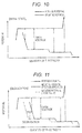
FIG. 10 is a chart showing correlation between a positive potential and a quantity of electricity, and correlation between a negative potential and a quantity of electricity. -
FIG. 11 is a chart showing correlation between a positive potential and a quantity of electricity, and correlation between a negative potential and a quantity of electricity. -
FIG. 12 is a chart showing C-V correlation characteristics of a secondary battery in Embodiment 2. -
FIG. 13 is a chart enlarging a part ofFIG. 11 . -
FIG. 14 is a flowchart showing a process for resetting a full-charge capacity Ct based on a record of environmental temperature inEmbodiment 4. -
FIG. 15 is a chart showing charge characteristics of a secondary battery (showing a capacity difference M between full-charge state and near-full-charge state). - First, an outline of a state estimation device disclosed according to one embodiment will be described. The state estimation device includes: a current integration unit configured to integrate a current that flows through the energy storage device; and a first estimation unit configured to estimate a full-charge capacity of the energy storage device, wherein the energy storage device has a correlation characteristic of correlation between a residual capacity C and an open voltage V, the correlation characteristic including a constant region in which a time change in the correlation characteristic is relatively smaller than an other region, and the first estimation unit performs: calculation of a residual capacity Cp of the energy storage device at a measuring point P based on an open voltage Vp of the energy storage device at the measuring point P included in the constant region, and on the correlation characteristic; and estimation of a full-charge capacity Co of the energy storage device based on the residual capacity Cp at the measuring point P that has been calculated, and on an accumulated charge-discharge amount X of the energy storage device from a full-charge state to the measuring point P, the full-charge state satisfying a full charge condition. According to the above state estimation device, an estimation accuracy for estimating a full-charge capacity can be kept regardless of time passage from the initial state.
- The state estimation device may be provided with the following configurations.
- The first estimation unit may perform: calculation of a minimum value Cpmin and a maximum value Cpmax of the residual capacity Cp of the energy storage device at the measuring point P based on the open voltage Vp of the energy storage device at the measuring point P and on the correlation characteristic; and calculation of a minimum value Comin and a maximum value Comax of the full-charge capacity Co of the energy storage device respectively by adding the accumulated charge-discharge amount X to the minimum value Cpmin and the maximum value Cpmax of the residual capacity Cp. According to this configuration, it is possible to calculate a possible range (minimum value Comin to maximum value Comax) of the full-charge capacity Co of the energy storage device.
- The constant region includes a low-change region in which a ratio of change of the open voltage V with respect to the residual capacity C is relatively smaller than another region. In the low-change region, it is difficult to specify the residual capacity Cp accurately based on the open voltage Vp, as the ratio of change of the open voltage V with respect to the residual capacity C is small. When the constant region includes the low-change region, it is preferable to calculate the range of the full-charge capacity Co, as errors are smaller.
- When the open voltage Vp is measured at two different measuring points P at which ratios of change of the open voltage V with respect to the residual capacity C are different, the first estimation unit may perform a process of calculating the minimum value Comin and the maximum value Comax of the full-charge capacity Co of the energy storage device by selecting one of the measuring points P whose ratio of change of the open voltage V is greater than the other. The possible range of the full-charge capacity Co may be restricted, that is, narrowed to a small range as compared to a case in which one of the measuring points P whose ratio of change of the open voltage V is smaller than the other.
- The first estimation unit may calculate the minimum value Comin and the maximum value Comax of the full-charge capacity Co of the energy storage device including at least one of a detection error of the full-charge state and an error of the accumulated charge-discharge amount X. This allows accurate calculation of the possible range (minimum value Comin to maximum value Comax) of the full-charge capacity.
- The state estimation device may include: a second estimation unit configured to estimate a full-charge capacity Ct of the energy storage device based on environmental temperature information; and a comparator unit configured to compare the full-charge capacity Ct of the energy storage device estimated based on the environmental temperature information with the minimum value Comin and the maximum value Comax of the full-charge capacity Co calculated using the correlation characteristic, wherein if the full-charge capacity Ct based on the environmental temperature information is outside a range from the minimum value Comin to the maximum value Comax, the full-charge capacity Ct based on the environmental temperature information is reset to a value within the range from the minimum value Comin to the maximum value Comax, the value being closer to the full-charge capacity Ct relative to a medium value of the range from the minimum value Comin to the maximum value Comax. With this configuration, it is possible to reset the estimated value of the full-charge capacity based on the environmental temperature information to a value closer to the true value.
- The state estimation device may include: a determination unit configured to determine life of the energy storage device by comparing the full-charge capacity Ct of the energy storage device estimated by the second estimation unit with a predetermined value. With this configuration, it is possible to determine the life of the energy storage device.
- Embodiment 1 will be described with reference to
FIG. 1 through FIG. 11 . -
FIG. 1 is a diagram illustrating a configuration of abattery pack 20 according to this embodiment. Thebattery pack 20 is mounted on an electric vehicle or a hybrid electric vehicle, for example, and is used to supply power to a power source driven by electrical energy. - As illustrated in
FIG. 1 , thebattery pack 20 includes an assembledbattery 30, acurrent sensor 40, and a battery manager (hereinafter, BM) 50 that manages the assembledbattery 30. The assembledbattery 30 is configured by a plurality ofsecondary batteries 31 that are connected in series. - The
secondary batteries 31 and thecurrent sensor 40 are connected in series via aline 35, and connected to abattery charger 10 mounted on an electric vehicle, or to aload 10 such as a power source provided within the electric vehicle or the like. - The
battery charger 10 serves a function of charging the assembledbattery 30. A charging method by thebattery charger 10 is a CC/CV (constant current/constant voltage) method, in which when a secondary battery 14 reaches a changeover voltage, the charging is switched from constant current charge to constant voltage charge. Further, thebattery charger 10 detects a charge current using a built-in current sensor (not shown). If the charge current falls under a first threshold value, thebattery charger 10 determines that the battery is fully charged and stops charging (seeFIG. 2 ). That is, in this embodiment, thebattery charger 10 determines a full-charge state under a condition that the charge current falls under the first threshold value. Alternatively, other than the method based on the charge current, it is possible to employ a method of detecting the full-charge state by determining whether or not a total voltage of the assembledbattery 30 reaches a specific value. - The
current sensor 40 serves a function of detecting a current that flows through thesecondary batteries 31. Thecurrent sensor 40 is configured to measure a current value of thesecondary batteries 31 at a constant cycle, and to transmit data of the measured current value that has been measured to acontroller 60. - The BM 50 includes the
controller 60, avoltage detection circuit 80, and atemperature sensor 95. Here, each of thesecondary batteries 31 is one example of the "energy storage device", theBM 50 is one example of the "state estimation device", and thecontroller 60 is one example of the "current integration unit", the "first estimation unit", the "second estimation unit", and the "comparator unit". - The
voltage detection circuit 80 is connected to both sides of each of thesecondary batteries 31 via detection lines, and serves a function of measuring a voltage of each of thesecondary batteries 31 in response to an instruction from thecontroller 60. Thetemperature sensor 95 serves a function of measuring an environmental temperature T [°C] of thesecondary batteries 31 either in a contacting manner or in a contactless manner. Here, thevoltage detection circuit 80 is one example of the "voltage detection unit". WhileFIG. 1 shows the configuration in which thetemperature sensor 95 is included in theBM 50, thetemperature sensor 95 may be provided outside the BM 50 (near each of thesecondary batteries 31, for example). In that case, a detection signal (temperature information) from thetemperature sensor 95 may be input to thecontroller 60 via an input unit or a signal conversion unit (e.g., A/D converter) not shown but disposed in theBM 50. Further, while the configuration in which thevoltage detection circuit 80 is included in theBM 50 is disclosed, thevoltage detection circuit 80 may also be provided outside theBM 50. In that case, too, a detection signal (voltage information) detected from each of the secondary batteries may be input to thecontroller 60 via an input unit or a signal conversion unit not shown but disposed in theBM 50. - The
controller 60 includes a central processing unit (hereinafter, CPU) 61, amemory 63, acounter 65, and acommunication unit 67. Thecontroller 60 serves a function of calculating a full-charge capacity Ct of each of thesecondary batteries 31 and a possible range (from Comin to Comax) of a full-charge capacity Co of each of thesecondary batteries 31. Thecontroller 60 is one example of the "first estimation unit", the "second estimation unit", and the "comparator unit". - The
memory 63 stores a calculation program for executing a process of calculating the possible range (from Comin to Comax) of the full-charge capacity Co of each of thesecondary batteries 31, and data required to execute the program, such as data of C-V correlation characteristics shown inFIG. 4 , for example. In addition, thememory 63 also stores a program for calculating the full-charge capacity Ct of each of thesecondary batteries 31 based on a record of environmental temperature, a program for executing a process of resetting the full-charge capacity Ct, and data required to execute the programs, such data of a reduced amount W of the full-charge capacity Co as shown inFIG. 7 , for example. - The counter T serves a function of counting elapsed time n that will be later described. The
communication unit 67 is connected to an ECU (Electronic Control Unit) 100 mounted on a vehicle so as to be able to communicate with theECU 100, and serves a function of communicating with theECU 100 mounted on a vehicle. Here, thebattery pack 20 is also provided with an operating unit for accepting an input from a user (not shown), and an indicator indicating a state and the like of the secondary batteries 31 (not shown). - In the following description, an iron-phosphate-based lithium ion battery using lithium iron phosphate (LiFePO4) as a positive active material and graphite as a negative active material is taken as one example of the
secondary batteries 31. -
FIG. 3 shows SOC-V correlation characteristics of thesecondary batteries 31, expressing SOC [%] by a horizontal axis, and an open circuit voltage (open voltage) V [V] by a vertical axis. InFIG. 3 , a solid line indicates an SOC-V correlation characteristic of asecondary battery 31A with an initial capacity (initial state), and a dashed line indicates an SOC-V correlation characteristic of asecondary battery 31B after capacity degradation due to a predetermined time passage from the initial state. As shown inFIG. 3 , the SOC-V correlation characteristic of thesecondary battery 31B after capacity degradation due to the predetermined time passage from the initial state include only few region that matches the SOC-V correlation characteristic of thesecondary battery 31A with an initial capacity. That is, thesecondary battery 31 has a characteristic such that its SOC-V correlation characteristic changes with time. -
FIG. 4 shows C-V correlation characteristics of thesecondary batteries 31, expressing the residual capacity C [Ah] by a horizontal axis, and the open voltage V [V] by a vertical axis. InFIG. 4 , a solid line indicates a C-V correlation characteristic of thesecondary battery 31A with an initial capacity (initial state), and a dashed line indicates a C-V correlation characteristic of thesecondary battery 31B after capacity degradation due to a predetermined time passage from the initial state. - As shown in
FIG. 4 , thesecondary battery 31 has a characteristic such that along with capacity degradation due to time passage, a rising edge J of the open voltage V near the full-charge capacity shifts to a side on which the residual capacity is lower (left side inFIG. 4 ). In this example, as shown inFIG. 4 , the rising edge J shifts in a range from 47 [Ah], which is a minimum shifting point (left side inFIG. 4 ) toward a side on which the residual capacity is higher. A region in which the residual capacity C is equal to or higher than 47 [Ah] corresponds to a "shift region F2" in which the rising edge J shifts along with capacity degradation due to time passage. - On the other hand, in a region in which the residual capacity C is lower than 47 [Ah], the C-V correlation characteristic is substantially the same regardless of the occurrence of capacity degradation with time. This region corresponds to a "constant region F1" in which the C-V correlation hardly changes with time.
- A reason why the C-V correlation characteristic of the
secondary battery 31 includes the "constant region F1" in which the C-V correlation hardly changes with time shall be stated below. The voltage of thesecondary battery 31 may be expressed by a difference between a positive potential and a negative potential, as shown inFIG. 10 . With the lithium ionsecondary battery 31, as shown inFIG. 11 , capacity degradation from the initial state tends to occur due to relative displacement between the positive potential and the negative potential when charge and discharge are repeated. As shown inFIG. 10 and FIG. 11 , the positive potential and the negative potential include a flat region in which a change in the open voltage [V] with respect to capacity [Ah] is substantially zero. Therefore, even when there is relative displacement between the positive potential and the negative potential, there is a region in which there is no difference between the positive potential and the negative potential, that is, the C-V correlation hardly changes with time. - The constant region F1 includes a first low-change region L1 in which a ratio of change of the open voltage V with respect to the residual capacity C is relatively small, and a first high-change region H1 and a second high-change region H2 in which the ratio of change of the open voltage V with respect to the residual capacity C is relatively large.
- In the first low-change region L1, the residual capacity C is in a range of 22-43 [Ah], and the open voltage V is in a range from 3.30 [V] to 3.31 [V]. The first high-change region H1 is positioned on a side on which the residual capacity is lower (left side in
FIG. 4 ) with respect to the low-change region L1, and within a range in which the open voltage V is equal to or lower than 3.30 [V]. The second high-change region H2 is positioned on a side on which the residual capacity is higher (right side inFIG. 4 ) with respect to the low-change region L1, and within a range in which the open voltage V is from 3.31 [V] to 3.34 [V]. - The shift region F2 includes a second low-change region L2 in which the ratio of change of the open voltage V with respect to the residual capacity C is relatively small, and a third high-change region H3 in which the ratio of change of the open voltage V with respect to the residual capacity C is relatively large. In the second low-change region L2, the residual capacity C is in a range of 47-67 [Ah], and the open voltage V is generally constant at 3.34 [V]. In the third high-change region H3, the residual capacity C is equal to or higher than 67 [Ah], and the open voltage V is higher than 3.34 [V].
- In this embodiment, the possible range (from Comin to Comax) of the full-charge capacity Co is calculated using the C-V correlation characteristic, through the following steps (a) to (c).
- (a) Measuring the open voltage Vp at an arbitrary measuring point P included in the constant region F1.
- (b) Calculating the minimum value Cpmin and the maximum value Cpmax of the residual capacity Cp of the
secondary battery 31 at the measuring point P, based on the open voltage Vp at the measuring point P and the C-V correlation characteristic. - (c) Calculating the minimum value Comin and the maximum value Comax of the full-charge capacity Co of the
secondary battery 31, respectively, by adding the accumulated charge-discharge amount X of thesecondary battery 31 from the full-charge state to the measuring point P to the minimum value Cpmin and the maximum value Cpmax of the residual capacity Cp. - As shown in
FIG. 5 , the minimum value Cpmin and the maximum value Cpmax of the residual capacity Cp may be calculated using the C-V correlation characteristic based on the residual capacity Cp corresponding to the open voltage Vp. For example, if an error of a voltage value detected by thevoltage detection circuit 80 is ±A [V], the residual capacity C corresponding to an open voltage (Vp+A) obtained by adding an error A to the open voltage Vp may be taken as the maximum value Cpmax, and the residual capacity C corresponding to an open voltage (Vp-A) obtained by subtracting the error A from the open voltage Vp may be taken as the minimum value Cpmin. - Next, a sequence for calculating the possible range for the full-charge capacity Co will be described with reference to
FIG. 6 . - The sequence for calculating the possible range (from Comin to Comax) for the full-charge capacity Co shown in
FIG. 6 includes steps S10 to S80, which are executed periodically after starting monitoring the assembledbattery 30, for example. - Upon starting of the sequence, the
controller 60 performs a process of determining whether or not thesecondary battery 31 is in a full-charge state (S10). Thecontroller 60 is able to determine whether or not thesecondary battery 31 is in the full-charge state by detecting an operating condition of thebattery charger 10 through communication. Specifically, the full-charge state of thesecondary battery 31 may be detected by reception of a full-charge completion notice, which notifies the completion of charging thesecondary battery 31, from thebattery charger 10. Alternatively, the full-charge state may be detected by detecting the open voltage V of thesecondary battery 31. If thesecondary battery 31 is not in the full-charge state, the process of S10 is repeatedly performed to wait until thesecondary battery 31 is brought into the full-charge state. - If the
secondary battery 31 is charged by thebattery charger 10 and is brought into the full-charge state, the full-charge completion notice is sent from thebattery charger 10 to thecontroller 60. With this, thecontroller 60 determines that thesecondary battery 31 is brought into the full-charge state (S10: YES), thecontroller 60 performs a process of integrating a current value measured by thecurrent sensor 40, and measuring the accumulated charge-discharge amount X from the full-charge state (S20). Specifically, the process of integrating a current value measured by thecurrent sensor 40 taking discharge as plus and charge as minus. The charge-discharge amount X of thesecondary battery 31 is measured and accumulated as the assembledbattery 30 is used (discharged or charged) from the full-charge state. - Then, as a next process, the
controller 60 compares the current value of thesecondary battery 31 with a first threshold value (for example, a value at which the current is substantially assumed to be zero) (S30). If a state in which the current value is smaller than the first threshold value, that is, the current is assumed to be substantially zero in this example, continues for a certain period of time, thecontroller 60 performs a process of measuring the open voltage V of the secondary battery 31 (S40). In this example, the process of measuring the open voltage V is performed for one representativesecondary battery 31 in the plurality of thesecondary batteries 31 constituting the assembledbattery 30. It should be noted that a time period until the voltage becomes stable after completion of charging varies depending on temperature. Therefore, it is preferable to adjust a time period for waiting for stabilization (the certain period of time described above) depending on the temperature. - Thereafter, the
controller 60 determines whether or not the measuring point P of the open voltage V is included in the constant region F1 of thesecondary battery 31. In the example shown inFIG. 4 , the open voltage V at a boundary point Z between the constant region F1 and the shift region F2 is 3.34 [V]. - If the open voltage V of the
secondary battery 31 is equal to or higher than 3.34 [V], it is determined that the measuring point P of the open voltage V is included in the shift region F2 (S50: NO). On the other hand, if the open voltage V of thesecondary battery 31 is lower than 3.34 [V], it is determined that the measuring point P of the open voltage V is included in the constant region F1. - The residual capacity C is kept decreasing if the battery remains in a use state without charging after detection of the full-charge state, and eventually the state of the
secondary battery 31 shifts to the constant region F1. Then, if the current value of thesecondary battery 31 is substantially assumed to be zero after the state of thesecondary battery 31 has completely shifted to the constant region F1, the open voltage V of thesecondary battery 31 becomes lower than 3.34 [V]. Thus, upon execution of S50, thecontroller 60 determines that the measuring point P of the open voltage V of thesecondary battery 31 is within the constant region F1. - Then, when it is determined that the measuring point P is within the constant region F1, the
controller 60 terminates integration of the current value measured by the current sensor 40 (S60). With this, the accumulated charge-discharge amount X from the full-charge state to the measuring point P is obtained. - Next, the
controller 60 calculates the residual capacity Cp of thesecondary battery 31 at the measuring point P within the constant region F1 based on the open voltage Vp at the measuring point P and the C-V correlation characteristic. Specifically, thecontroller 60 first calculates the residual capacity Cp of thesecondary battery 31 at the measuring point P referring to the C-V correlation characteristic stored in thememory 63 for the open voltage Vp at the measuring point P, and then calculates the minimum value Cpmin and the maximum value Cpmax of the residual capacity Cp (S70). - Specifically, if an error of a voltage value detected by the
voltage detection circuit 80 is ±A [V], the residual capacity C corresponding to an open voltage (Vp+A) obtained by adding an error A to the open voltage Vp is taken as the maximum value Cpmax, and the residual capacity C corresponding to an open voltage (Vp-A) obtained by subtracting the error A from the open voltage Vp is taken as the minimum value Cpmin (seeFIG. 5 ). - Next, the
controller 60 performs a process of calculating the minimum value Comin and the maximum value Comax of the full-charge capacity Co (S80). Specifically, the minimum value Comin of the full-charge capacity Co is obtained by adding the accumulated charge-discharge amount X from the full-charge state to the measuring point P to the minimum value Cpmin of the residual capacity Cp at the measuring point P (Expression (1) below). Further, the maximum value Comax of the full-charge capacity Co is obtained by adding the accumulated charge-discharge amount X from the full-charge state to the measuring point P to the maximum value Cpmax of the residual capacity Cp at the measuring point P (Expression (2) below).

- In this manner, it is possible to calculate the possible range (from Comin to Comax) of the full-charge capacity Co of the
secondary battery 31. Because the measuring point P for calculating Cpmin and Cpmax is set in the constant region F1, the calculation accuracy can be kept for calculating the possible range (from Comin to Comax) of the full-charge capacity Co regardless of the time passage from the initial state. - In Embodiment 1, lithium ion batteries are adopted in which lithium iron phosphate is used for a positive electrode and graphite is used for a negative electrode. Lithium ion batteries other than the above may be used. Any type (any combination of a positive electrode and a negative electrode) may be used and an aspect of the present invention is applicable, as long as a change in C-V correlation characteristics between a residual capacity C and an open voltage V with respect to hours of use of a battery is small (smaller correlation characteristics time change). Alternatively, if the correlation characteristics time change may be expressed by a function of time, it is possible to correct by the function, and thus an aspect of the present invention may also be applicable to C-V correlation characteristics that is predictable.
- It is known that the reduced amount W of the full-charge capacity Ct of the
secondary battery 31 depends on a record of temperature of the assembledbattery 30. Thus, thecontroller 60 of theBM 50 calculates the reduced amount W of the full-charge capacity Ct of thesecondary battery 31 based on environmental temperature information of the assembled battery 30 (FIG. 8 , S100). - Specifically, as shown in
FIG. 7 , thememory 63 stores data of the reduced amount W of the full-charge capacity Ct for the environmental temperature T of the assembledbattery 30 at each temperature. The reduced amount W is stored as a function taking the environmental temperature T and the elapsed time n as variables, as the reduced amount W also depends on the elapsed time n under environmental temperature. - For example, if the environmental temperature of the assembled battery is "T1" and the elapsed time is "n1", the reduced amount W of the full-charge capacity Ct is W(T1, n1). Further, if the environmental temperature of the assembled battery is "T2" and the elapsed time is "n2", the reduced amount W of the full-charge capacity Ct is W(T2, n2).
- After starting using the
secondary battery 31, thecontroller 60 continuously obtains data for the environmental temperature T and the elapsed time n of the assembledbattery 30. Then, thecontroller 60 performs a process of calculating the reduced amount W of the full-charge capacity Ct at a certain frequency. Further, thecontroller 60 calculates the full-charge capacity Ct of thesecondary battery 31 by subtracting the reduced amount W that has been calculated from an initial value Cos of the full-charge capacity Ct, and updates and stores the data in thememory 63. In this manner, theBM 50 updates and maintains latest data (estimated value) of the full-charge capacity Ct based on the record of environmental temperature.
-
FIG. 8 is a flowchart showing a process for resetting the full-charge capacity Ct based on the record of environmental temperature. In the method of estimating the full-charge capacity Ct based on the record of environmental temperature, errors in temperature measurement by thetemperature sensor 95 are accumulated, and an amount of the errors increases if elapsed time after stating the estimation becomes long. - Thus, the
controller 60 performs a process of comparing the elapsed time after stating the estimation of the full-charge capacity Ct with a specific value (S110). Then, if the elapsed time after stating the estimation is over the specific value, thecontroller 60 performs a process of comparing the estimated value of the full-charge capacity Ct based on the record of environmental temperature with the possible range (from Comin to Comax) for the full-charge capacity Co (S120). Thereafter, if the estimated value of the full-charge capacity Ct based on the record of environmental temperature is outside the possible range (from Comin to Comax), thecontroller 60 resets the estimated value of the full-charge capacity Ct based on the record of environmental temperature to a value within the possible range (from Comin to Comax) (S130). - After the resetting, the
controller 60 performs a process of estimating the full-charge capacity Ct based on the record of environmental temperature taking the reset value as an initial value. When the elapsed time after starting the estimate exceeds the specific value, thecontroller 60 performs a process of comparing the estimated value of the full-charge capacity Ct based on the record of environmental temperature with the possible range (from Comin to Comax) for the full-charge capacity Co. - Then, if the estimated value of the full-charge capacity Ct based on the record of environmental temperature is outside the possible range (from Comin to Comax), the
controller 60 resets the estimated value of the full-charge capacity Ct again to a value within the possible range (from Comin to Comax). - Here, the resetting of the estimated value may be performed in a half of the possible range (from Comin to Comax) on a side closer to the compared estimated value. For example, as shown in
FIG. 9 , if the estimated value of the full-charge capacity Ct is outside a lower side of the range, it is preferable that the estimated value is reset (overwritten) to a value in a range from a medium value (Cp+X) of the possible range to the minimum value (Comin). In this manner, it is possible to reset the estimated value of the full-charge capacity Ct based on the record of environmental temperature to a value closer to a true value. - According to the
BM 50 of Embodiment 1, it is possible to calculate the possible range (from Comin to Comax) for the full-charge capacity Co. Further, the estimated value of the full-charge capacity Ct based on the record of environmental temperature is compared with the possible range (from Comin to Comax) for the full-charge capacity Co, and reset to a value within the possible range (from Comin to Comax) if the estimated value is outside the possible range. Therefore, it is possible to reduce accumulation of errors in temperature measurement by thetemperature sensor 95 when the full-charge capacity Ct is estimated. - Next, Embodiment 2 of the present invention will be described with reference to
FIG. 12 andFIG. 13 . Similarly to thebattery pack 20 according to Embodiment 1, thebattery pack 20 according to Embodiment 2 includes the assembledbattery 30, thecurrent sensor 40, and thebattery manager 50 that manages the assembledbattery 30. - In Embodiment 1, the open voltage Vp is measured at one measuring point P within the constant region F1 when the possible range (from Comin to Comax) for the full-charge capacity Co is calculated by the
controller 60. In Embodiment 2, when the possible range (from Comin to Comax) for the full-charge capacity Co is calculated by thecontroller 60, the open voltage Vp is measured at two measuring points P within the constant region F1. Then, a process of determining whether or not a ratio of change of the open voltage V with respect to the residual capacity C is different between the two measuring points P is performed. - In this example, the first low-change region L1, the first high-change region H1, and the second high-change region H2 are included in the constant region F1. Therefore, as shown in
FIG. 12 , when the measuring point P1 is included in the low-change region L1 and the measuring point P2 is included in either the first high-change region H1 or the second high-change region H2, it is determined that the ratio of change of the open voltage V with respect to the residual capacity C is different between the two measuring points P1, P2. - If the ratio of change of the open voltage V with respect to the residual capacity C is different between the two measuring points P1, P2, one of the measuring points P whose ratio of change of the open voltage V is higher is selected, and a process of calculating the minimum value Comin and the maximum value Comax of the full-charge capacity Co of the energy storage device is performed. For example, in the example shown in
FIG. 12 , a possible range of the possible range (from Comin to Comax) for the full-charge capacity Co is calculated based on the measuring point P2 included in the second high-change region H2. - Specifically, the
controller 60 calculates the residual capacity Cp2 of thesecondary battery 31 at the measuring point P2 referring to the C-V correlation characteristic stored in thememory 63 for the open voltage Vp2 at the measuring point P2. Further, thecontroller 60 calculates the minimum value Cpmin and the maximum value Cpmax of the residual capacity Cp2 by adding a capacity corresponding to an error ±A of the voltage value detected by the voltage detection circuit 80 (seeFIG. 13 ). - Then, the minimum value Comin of the full-charge capacity Co is obtained by adding the accumulated charge-discharge amount X from the full-charge state to the measuring point P2 to the minimum value Cpmin of the residual capacity Cp2 at the measuring point P2. Further, the maximum value Comax of the full-charge capacity Co is obtained by adding the accumulated charge-discharge amount X from the full-charge state to the measuring point P to the maximum value Cpmax of the residual capacity Cp2 at the measuring point P2.
- In this manner, the possible range (from Comin to Comax) for the full-charge capacity Co may be narrowed, that is, restricted to a small range as compared to the case in which the measuring point P1 whose ratio of change of the open voltage V is smaller. Therefore, it is possible to reset the estimated value of the full-charge capacity Ct based on the record of environmental temperature to a value further closer to a true value.
- Next, Embodiment 3 of the present invention will be described. Similarly to the
battery pack 20 according to Embodiment 1, thebattery pack 20 according to Embodiment 3 includes the assembledbattery 30, thecurrent sensor 40, and thebattery manager 50 that manages the assembledbattery 30. Embodiment 3 is different from Embodiment 1 in the method of calculating the minimum value Comin and the maximum value Comax of the full-charge capacity Co. - In Embodiment 1, the
controller 60 calculates the minimum value Comin of the full-charge capacity Co based on Expression (1), and the maximum value Comax based on Expression (2). In Embodiment 3, thecontroller 60 calculates the minimum value Comin of the full-charge capacity Co based on Expression (4), and the maximum value Comax of the full-charge capacity Co based on Expression (5).

- Here, "α" is an error of the accumulated charge-discharge amount X, and "β" is a detection error of the full-charge state.
- In Embodiment 3, Expression (4) and Expression (5) include the error α of the accumulated charge-discharge amount X and the detection error β of the full-charge state, and therefore it is possible to calculate the minimum value Comin and the maximum value Comax of the full-charge capacity Co accurately.
- The error of the accumulated charge-discharge amount X is an error of current integration, that is, accumulation of measurement errors by the
current sensor 40. The detection error of the full-charge state is an error that occurs due to detection shift at timing when the charge current falls under the first threshold value. - Next,
Embodiment 4 of the present invention will be described with reference toFIG. 14 . Similarly to thebattery pack 20 according to Embodiment 1, thebattery pack 20 according toEmbodiment 4 includes the assembledbattery 30, thecurrent sensor 40, and theBM 50. In Embodiment 1, the full-charge capacity Ct of thesecondary battery 31 is calculated based on data of the environmental temperature T and the elapsed time n. InEmbodiment 4, a process of determining life of the assembledbattery 30 based on the full-charge capacity Ct is added. - Specifically, in
Embodiment 4, two steps of S103 and S105 are added to the process of resetting the full-charge capacity Ct based on the record of environmental temperature described with reference toFIG. 8 in Embodiment 1. In S103, thecontroller 60 performs a process of comparing the full-charge capacity Ct of thesecondary battery 31 calculated based on the environmental temperature information with a predetermined value (a battery capacity at an end of life). Then, if the full-charge capacity Ct is lower than the predetermined value, thecontroller 60 determines that it is an end of life of the assembledbattery 30, and notifies theECU 100 of the end of life of the assembledbattery 30. Then, upon reception of "the notification on the end of life of the assembledbattery 30", theECU 100 gives the user a warning to encourage exchanging of the battery. In this manner, the user may be encouraged to exchange the battery, and it is possible to prevent a battery from being used after its life has ended. - If the full-charge capacity Ct is higher than the predetermined value (the battery is not at the end of life), the process in and after S110 is performed in the same manner as in Embodiment 1. The
controller 60 is one example of a "determination unit" in the present invention. - Next, Embodiment 5 of the present invention will be described. Similarly to the
battery pack 20 according to Embodiment 1, thebattery pack 20 according to Embodiment 5 includes the assembledbattery 30, thecurrent sensor 40, and thebattery manager 50 that manages the assembledbattery 30. In Embodiment 1, the possible range (from Comin to Comax) for the full-charge capacity Co is calculated by thecontroller 60. In Embodiment 5, thecontroller 60 calculates the full-charge capacity Co based on the open voltage Vp at an arbitrary measuring point P within the constant region F1 and the accumulated charge-discharge amount X from the full-charge state to the measuring point P. Specifically, the full-charge capacity Co is calculated based on Expression (6) below.
- Here, "Cp" is the residual capacity at an arbitrary measuring point P within the constant region F1, and "X" is the accumulated charge-discharge amount from the full-charge state to the measuring point P.
- In Embodiment 5, an estimation accuracy for estimating a full-charge capacity Co can be kept regardless of time passage from the initial state. Further, the full-charge capacity Co of the
secondary battery 31 may be calculated without discharging to an end-of-discharge voltage. - In the meantime, as described in Embodiment 1, the constant region F1 includes the first low-change region L1, the first high-change region H1, and the second high-change region H2. In the first low-change region L1, the ratio of change of the open voltage V with respect to the residual capacity C is small. Accordingly, when the residual capacity Cp corresponding to the measuring point P is obtained using the C-V correlation characteristic, an error of the residual capacity Cp, that is, a calculation error of the full-charge capacity Co increases due to a measurement error of the open voltage V. Therefore, when the full-charge capacity Co is calculated based on the residual capacity Cp at the measuring point P within the first low-change region L1, it is preferable to use the
voltage detection circuit 80 whose voltage measurement is highly accurate. - In the first high-change region H1 and the second high-change region H2, the ratio of change of the open voltage V with respect to the residual capacity C is large even within the constant region F1, and therefore an error of the residual capacity Cp, that is, an error of the full-charge capacity Co is relatively small. Accordingly, the full-charge capacity Co may be calculated by selecting the measuring point P in the first high-change region H1 or the second high-change region H2. In this manner, it is possible to obtain the full-charge capacity Co accurately without using the
voltage detection circuit 80 with high accuracy. Here, a region in which the measuring point P is included may be determined by referring the C-V correlation characteristic for the open voltage Vp at the measuring point P. - The present invention is not restricted to the embodiments described above. The following embodiments may also be included within the technical scope of the present invention.
- (1) In Embodiment 1, the possible range (from Comin to Comax) for the full-charge capacity Co is calculated in the following order. The possible range (from Comin to Comax) for the full-charge capacity Co is calculated in the order of: "detection of the full-charge state" → "current integration (charge-discharge)" → "measurement of the open voltage Vp at the measuring point P within the constant region" → "calculation of the minimum value Cpmin and the maximum value Cpmax of the residual capacity Cp corresponding to the measuring point P" → "addition of the accumulated charge-discharge amount X.
Other than the above order, the possible range (from Comin to Comax) for the full-charge capacity Co may be calculated in the order of: "measurement of the open voltage Vp at the measuring point P within the constant region" → "calculation of the minimum value Cpmin and the maximum value Cpmax of the residual capacity Cp corresponding to the measuring point P" → "current integration (charge-discharge)" → "detection of the full-charge state" → "addition of the accumulated charge-discharge amount X", for example. - (2) Embodiment 1 shows the example in which, as the C-V correlation characteristic of the
secondary battery 31, the C-V correlation characteristics are substantially identical in "the constant region F1" in which the residual capacity C is smaller than 47 [Ah], regardless of occurrence of capacity degradation due to time passage from the initial state. However, the C-V correlation characteristics are not necessary to be identical in "the constant region F1" as shown, as long as a change in the C-V correlation is relatively smaller than the other regions (the shift region F2) regardless of occurrence of capacity degradation. - (3) Embodiment 1 takes the lithium ion
secondary battery 31 as one example of the energy storage device. However, the energy storage device may be other than the lithium ion battery, as long as the battery has the C-V correlation characteristic having a constant region in which, as shown inFIG. 4 , a time change in the C-V correlation is relatively smaller than the other regions (shift region). - (4) Embodiment 1 shows the example in which the
current sensor 40 is provided separately from theBM 50. However, thecurrent sensor 40 may be configured to be included in theBM 50. - (5) In Embodiment 3, the expressions for calculating the minimum value Comin and the maximum value Comax of the full-charge capacity Co include the error α of the accumulated charge-discharge amount X and the detection error β of the full-charge state. However, an expression including only one of the error α and the detection error β may be used.
- (6) Embodiment 1 shows the example in which in the method of calculating the accumulated charge-discharge amount X from the full-charge state to the measuring point P, the full-charge state is first detected, and then the accumulated charge-discharge amount X from the full-charge state to the measuring point P is actually measured. However, other than such a method, the accumulated charge-discharge capacity X may be calculated using a capacity difference M from the full-charge state to a near-full-charge state.
- For example, as shown in
FIG. 15 , if the "capacity difference M" between a full-charge state (a state in which the charge current in CV charge corresponds to a first threshold value) G1 and a near-full-charge state (a state in which the charge current corresponds to a second threshold value that is higher than the first threshold value) G2 is known in advance from data such as experimental data, it is possible, by measuring an accumulated charge-discharge amount X1 from the near-full-charge state G2 to the measuring point P, to obtain the accumulated charge-discharge amount X by Expression (7) below based on the measured value X1 by the measurement and the capacity difference M.
- X: the accumulated charge-discharge amount from the full-charge state G1 to the measuring point P
- X1: the accumulated charge-discharge amount from the near-full-charge state G2 to the measuring point P (measured value)
- M: the capacity difference between the full-charge state G1 and the near-full-charge state G2 (estimated value based on data such as experimental data)
- In this manner, it is possible to obtain an advantage that the accumulated charge-discharge amount X and the possible range (from Comin to Comax) for the full-charge capacity Co may be obtained by charging to the near-full-charge state G2 that is close to the full-charge state G1, instead of charging to the full-charge state G1.
- (7) In Embodiment 1, the open voltage V of the
secondary battery 31 is compared with the open voltage at the boundary point Z between the constant region F1 and the shift region F2 in order to determine whether the measuring point P is included in the constant region F1. - If the C-V correlation characteristics contain a region where a time change is large (e.g., the shift region F2 in
FIG. 4 ) and a region where a time change is small (e.g., the constant region F1 inFIG. 4 ), it can be determined in which region the measuring point P is included by comparing the residual capacity Cp of thesecondary battery 31 with a predetermined value U. Thecontroller 60 may perform processes of (A) to (C) described below to calculate the full-charge capacity Co. The predetermined value U may be a boundary point between the region where a time change is large and the region where a time change is small. In the example ofFIG. 4 , the predetermined value may be set to 47 [Ah]. - (A) Measuring the open voltage Vp of the
secondary battery 31 at an arbitrary measuring point Pat which the current value is equal to or lower than a first threshold value. Calculating the residual capacity Cp of thesecondary battery 31 at the measuring point from the open voltage Vp by referring to the C-V correlation characteristics of thesecondary battery 31. - (B) Determining whether the calculated residual capacity Cp is equal to or lower than the predetermined value U.
- (C) Calculating the full-charge capacity Co of the secondary battery based on the residual capacity Cp and on the accumulated charge-discharge amount X from the full-charge state to the measuring point P. Specifically, similar to Expression (6) in Embodiment 5, the full-charge capacity Co is calculated by adding the minimum value Comin and the maximum value Comax of the full-charge capacity Co of the
secondary battery 31, respectively, by adding the accumulated charge-discharge amount X to the residual capacity Cp. - With the above method, similar to Embodiment 5, an estimation accuracy of the full-charge capacity can be kept regardless of time passage from the initial state.
- In the above process (C), estimation of the full-charge capacity Co is performed if the residual capacity Cp is equal to or less than the predetermined value. This is because the region where a time change is large is located on a high residual capacity side and the region where a time change is small is located on a low residual capacity side in the C-V correlation characteristics of the
secondary battery 31. If the residual capacity Cp is equal to or lower than the predetermined value U, the measuring point P can be determined to be contained in the region where a time change is small. In the above process (B), if the residual capacity Cp is more than the predetermined value U, then the process (C) is performed after the residual capacity Cp becomes equal to or less than the predetermined value U.
Claims (10)
- A state estimation device that estimates a state of an energy storage device, the state estimation device comprising:a current integration unit configured to integrate a current that flows through the energy storage device; anda first estimation unit configured to estimate a full-charge capacity of the energy storage device,wherein the energy storage device has a correlation characteristic of correlation between a residual capacity C and an open voltage V, the correlation characteristic including a constant region in which a time change in the correlation characteristic is relatively smaller than an other region, andthe first estimation unit performs:calculation of a residual capacity Cp of the energy storage device at a measuring point P based on an open voltage Vp of the energy storage device at the measuring point P included in the constant region, and on the correlation characteristic; andestimation of a full-charge capacity Co of the energy storage device based on the residual capacity Cp at the measuring point P that has been calculated, and on an accumulated charge-discharge amount X of the energy storage device from a full-charge state to the measuring point P, the full-charge state satisfying a full charge condition.
- The state estimation device according to claim 1, wherein
the first estimation unit performs:calculation of a minimum value Cpmin and a maximum value Cpmax of the residual capacity Cp of the energy storage device at the measuring point P based on the open voltage Vp at the measuring point P and the correlation characteristic; andcalculation of a minimum value Comin and a maximum value Comax of the full-charge capacity Co of the energy storage device respectively by adding the accumulated charge-discharge amount X to the minimum value Cpmin and the maximum value Cpmax of the residual capacity Cp. - The state estimation device according to claim 2, wherein
when the open voltage Vp is measured at two different measuring points P at which ratios of change of the open voltage V with respect to the residual capacity C are different, the first estimation unit performs a process of calculating the minimum value Comin and the maximum value Comax of the full-charge capacity Co of the energy storage device by selecting one of the measuring points P whose ratio of change of the open voltage V is greater than the other. - The state estimation device according to claim 2 or claim 3, comprising:a second estimation unit configured to estimate a full-charge capacity Ct of the energy storage device based on environmental temperature information; anda comparator unit configured to compare the full-charge capacity Ct of the energy storage device estimated based on the environmental temperature information with the minimum value Comin and the maximum value Comax of the full-charge capacity Co calculated using the correlation characteristic,wherein if the full-charge capacity Ct based on the environmental temperature information is outside a range from the minimum value Comin to the maximum value Comax, the full-charge capacity Ct based on the environmental temperature information is reset to a value within the range from the minimum value Comin to the maximum value Comax, the value being closer to the full-charge capacity Ct relative to a medium value of the range from the minimum value Comin to the maximum value Comax.
- The state estimation device according to claim 4, comprising:a determination unit configured to determine life of the energy storage device by comparing the full-charge capacity Ct of the energy storage device estimated by the second estimation unit with a predetermined value.
- A state estimation method of estimating a state of an energy storage device having a correlation characteristic of correlation between a residual capacity C and an open voltage V, the correlation characteristic including a constant region in which a time change in the correlation characteristic is relatively smaller than an other region, the method comprising:calculating a residual capacity Cp of the energy storage device at a measuring point P based on an open voltage Vp of the energy storage device at the measuring point P included in the constant region, and on the correlation characteristic; andestimating a full-charge capacity Co of the energy storage device based on the residual capacity Cp at the measuring point P that has been calculated, and on an accumulated charge-discharge amount X of the energy storage device between the measuring point P and a full-charge state satisfying a full charge condition.
- The state estimation method according to claim 6, wherein
in the calculating, a minimum value Cpmin and a maximum value Cpmax of the residual capacity Cp of the energy storage device at the measuring point P are calculated based on the open voltage Vp at the measuring point P and the correlation characteristic, and
in the estimating, a minimum value Comin and a maximum value Comax of the full-charge capacity Co of the energy storage device are respectively calculated by adding the accumulated charge-discharge amount X to the minimum value Cpmin and the maximum value Cpmax of the residual capacity Cp. - The state estimation method according to claim 6 or claim 7, wherein
when the open voltage Vp is measured at two different measuring points P at which ratios of change of the open voltage V with respect to the residual capacity C are different, the calculating and the estimating are performed by selecting one of the measuring points P whose ratio of change of the open voltage V is greater than the other. - A state estimation device that estimates a state of an energy storage device, the state estimation device comprising:a current integration unit configured to integrate a current that flows through the energy storage device; anda first estimation unit configured to estimate a full-charge capacity of the energy storage device,wherein the first estimation unit performs:calculation of a residual capacity Cp of the energy storage device at an arbitrary measuring point P based on an open voltage Vp of the energy storage device at the measuring point P, and on a correlation characteristic between a residual capacity C and the open voltage Vp;confirmation that the residual capacity Cp that has been calculated is equal to or lower than a predetermined value; andestimation of a full-charge capacity Co of the energy storage device based on the residual capacity Cp at the measuring point P, and on an accumulated charge-discharge amount X of the energy storage device from a full-charge state to the measuring point P, the full-charge state satisfying a full charge condition.
- A state estimation method of estimating a state of an energy storage device, the method comprising:calculating a residual capacity Cp of the energy storage device at an arbitrary measuring point P based on an open voltage Vp of the energy storage device at the measuring point P, and on a correlation characteristic between a residual capacity C and the open voltage Vp;confirming that the residual capacity Cp that has been calculated is equal to or lower than a predetermined value; andestimating a full-charge capacity Co of the energy storage device based on the residual capacity Cp at the measuring point P, and on an accumulated charge-discharge amount X of the energy storage device from the measuring point P to a full-charge state satisfying a full charge condition.
Applications Claiming Priority (2)
| Application Number | Priority Date | Filing Date | Title |
|---|---|---|---|
| JP2015122032 | 2015-06-17 | ||
| JP2016092347A JP6714838B2 (en) | 2015-06-17 | 2016-05-02 | State estimation device and state estimation method |
Publications (2)
| Publication Number | Publication Date |
|---|---|
| EP3106892A1 true EP3106892A1 (en) | 2016-12-21 |
| EP3106892B1 EP3106892B1 (en) | 2022-03-23 |
Family
ID=56132789
Family Applications (1)
| Application Number | Title | Priority Date | Filing Date |
|---|---|---|---|
| EP16173918.0A Active EP3106892B1 (en) | 2015-06-17 | 2016-06-10 | State estimation device and state estimation method |
Country Status (4)
| Country | Link |
|---|---|
| US (1) | US10330735B2 (en) |
| EP (1) | EP3106892B1 (en) |
| CN (1) | CN106257737B (en) |
| AU (1) | AU2016203834A1 (en) |
Cited By (4)
| Publication number | Priority date | Publication date | Assignee | Title |
|---|---|---|---|---|
| EP3364203A1 (en) * | 2017-02-20 | 2018-08-22 | GS Yuasa International Ltd. | Battery state estimation based on a shift in the soc-ocv-curve |
| CN111257780A (en) * | 2020-03-12 | 2020-06-09 | 王国平 | Storage battery health degree evaluation method and device and storage medium |
| EP3912852A1 (en) * | 2020-05-19 | 2021-11-24 | Volkswagen Ag | Method and system for testing a state of a battery in a vehicle |
| EP4152022A4 (en) * | 2021-07-22 | 2023-03-22 | Contemporary Amperex Technology Co., Limited | Method for determining full-charge capacity of battery pack, method for determining state of health of battery pack, system, and apparatus |
Families Citing this family (8)
| Publication number | Priority date | Publication date | Assignee | Title |
|---|---|---|---|---|
| WO2018181129A1 (en) * | 2017-03-31 | 2018-10-04 | 株式会社Gsユアサ | Power storage element management apparatus and power storage element management method |
| CN111295593A (en) * | 2017-10-30 | 2020-06-16 | 株式会社杰士汤浅国际 | Power storage system, capacity estimation device for secondary battery, and capacity estimation method for lead-acid battery |
| JP7066390B2 (en) * | 2017-12-13 | 2022-05-13 | 大和製罐株式会社 | Economic efficiency estimation device and economic efficiency estimation method for storage batteries |
| CN108790876B (en) * | 2018-06-06 | 2020-08-04 | 北京新能源汽车股份有限公司 | Method and device for adjusting feedback power of electric automobile and automobile |
| EP3813006B1 (en) | 2018-06-14 | 2023-12-20 | GS Yuasa International Ltd. | Communication device, information processing system, information processing method, and computer program |
| DE102018212545A1 (en) * | 2018-07-27 | 2020-01-30 | Audi Ag | Method for monitoring a state of a battery, monitoring device and motor vehicle |
| CN109782178A (en) * | 2019-01-29 | 2019-05-21 | 中国铁塔股份有限公司 | A kind of battery core Rong Fangfa and core capacitance device |
| FR3105432B1 (en) * | 2019-12-20 | 2021-12-24 | Accumulateurs Fixes | Method for determining the value of a parameter relating to the state of health of an electrochemical element in a battery, electronic management system of a battery, and corresponding battery |
Citations (7)
| Publication number | Priority date | Publication date | Assignee | Title |
|---|---|---|---|---|
| JP2003068369A (en) | 2001-08-23 | 2003-03-07 | Japan Storage Battery Co Ltd | Detecting method of total capacity of secondary battery and detector of total capacity |
| GB2448412A (en) * | 2007-04-10 | 2008-10-15 | Sanyo Electric Co | Battery full charge capacity detection |
| JP2010266221A (en) * | 2009-05-12 | 2010-11-25 | Honda Motor Co Ltd | Battery state estimating device |
| US20110307033A1 (en) * | 2010-06-14 | 2011-12-15 | Medtronic, Inc. | Charge level measurement |
| WO2012010955A2 (en) * | 2010-07-23 | 2012-01-26 | Toyota Jidosha Kabushiki Kaisha | Vehicle control device and vehicle control method |
| US20130110428A1 (en) * | 2011-10-26 | 2013-05-02 | Industrial Technology Research Institute | Method And System For Estimating A Capacity Of A Battery |
| US20150260795A1 (en) * | 2014-03-17 | 2015-09-17 | Commissariat à l'énergie atomique et aux énergies alternatives | Battery cell state-of-health estimation method |
Family Cites Families (27)
| Publication number | Priority date | Publication date | Assignee | Title |
|---|---|---|---|---|
| JP4052418B2 (en) | 2000-02-15 | 2008-02-27 | 日立マクセル株式会社 | Battery capacity detection method and apparatus, and battery pack |
| JP3649652B2 (en) | 2000-05-22 | 2005-05-18 | 日本電信電話株式会社 | Lithium ion battery capacity estimation method, deterioration determination device, and lithium ion battery pack |
| JP3935099B2 (en) | 2003-04-15 | 2007-06-20 | 株式会社デンソー | Internal state detection system for power storage device for vehicle |
| JP4074596B2 (en) | 2004-03-18 | 2008-04-09 | 日立マクセル株式会社 | Rechargeable battery or rechargeable battery pack |
| KR100824905B1 (en) * | 2006-08-24 | 2008-04-23 | 삼성에스디아이 주식회사 | Hybrid battery and full charge capacity calculation method thereof |
| JP4561859B2 (en) | 2008-04-01 | 2010-10-13 | トヨタ自動車株式会社 | Secondary battery system |
| JP4978662B2 (en) | 2009-06-24 | 2012-07-18 | トヨタ自動車株式会社 | CHARGE STATE ESTIMATION DEVICE AND CHARGE STATE ESTIMATION METHOD |
| JP5638779B2 (en) | 2009-08-24 | 2014-12-10 | 三洋電機株式会社 | Secondary battery characteristic detection method and secondary battery device |
| JP2011075443A (en) | 2009-09-30 | 2011-04-14 | Panasonic Electric Works Co Ltd | Power distribution system and method of calculating residual capacity of storage battery |
| WO2011122310A1 (en) * | 2010-03-30 | 2011-10-06 | 本田技研工業株式会社 | Method for detecting battery capacity of secondary battery |
| CN102834727B (en) | 2010-04-09 | 2015-03-25 | 丰田自动车株式会社 | Secondary battery degradation determination device and degradation determination method |
| JP5672778B2 (en) | 2010-06-08 | 2015-02-18 | 日産自動車株式会社 | Battery capacity display device and battery capacity display method |
| JP5282789B2 (en) | 2011-01-11 | 2013-09-04 | 株式会社デンソー | Battery capacity detection device for lithium ion secondary battery |
| US20130311119A1 (en) | 2011-01-31 | 2013-11-21 | Shigeto Tamezane | Method of detecting battery full-charge capacity |
| CN103392133A (en) * | 2011-03-07 | 2013-11-13 | 株式会社日立制作所 | Battery state estimating method and battery management system |
| JP2012239357A (en) | 2011-05-13 | 2012-12-06 | Sony Corp | Battery pack, electronic apparatus, electric power system and electric vehicle |
| JP2013053943A (en) * | 2011-09-05 | 2013-03-21 | Toyota Motor Corp | Device and method for estimation |
| JP5741389B2 (en) | 2011-11-09 | 2015-07-01 | トヨタ自動車株式会社 | A method for estimating a full charge capacity of a power storage device and a power storage system. |
| JP5409840B2 (en) | 2012-05-11 | 2014-02-05 | カルソニックカンセイ株式会社 | Apparatus for estimating cell state of battery pack |
| JP2013250071A (en) | 2012-05-30 | 2013-12-12 | Sanyo Electric Co Ltd | Full charge capacity detection device and storage battery system |
| JP5862478B2 (en) | 2012-06-25 | 2016-02-16 | トヨタ自動車株式会社 | Power storage system and control method |
| JP5673654B2 (en) * | 2012-11-16 | 2015-02-18 | トヨタ自動車株式会社 | Power storage system and full charge capacity calculation method |
| JP6300000B2 (en) * | 2013-02-20 | 2018-03-28 | 株式会社Gsユアサ | Charge state estimation device, charge state estimation method |
| JP2014169937A (en) | 2013-03-04 | 2014-09-18 | Denso Corp | Charge state calculation device |
| JP5812032B2 (en) | 2013-03-22 | 2015-11-11 | トヨタ自動車株式会社 | Power storage system and method for estimating full charge capacity of power storage device |
| JP6160473B2 (en) | 2013-12-20 | 2017-07-12 | トヨタ自動車株式会社 | Power storage system |
| JP6156216B2 (en) | 2014-03-25 | 2017-07-05 | 株式会社デンソー | Full charge capacity estimation device |
-
2016
- 2016-06-08 AU AU2016203834A patent/AU2016203834A1/en not_active Abandoned
- 2016-06-10 EP EP16173918.0A patent/EP3106892B1/en active Active
- 2016-06-10 US US15/179,718 patent/US10330735B2/en active Active
- 2016-06-15 CN CN201610424642.3A patent/CN106257737B/en active Active
Patent Citations (7)
| Publication number | Priority date | Publication date | Assignee | Title |
|---|---|---|---|---|
| JP2003068369A (en) | 2001-08-23 | 2003-03-07 | Japan Storage Battery Co Ltd | Detecting method of total capacity of secondary battery and detector of total capacity |
| GB2448412A (en) * | 2007-04-10 | 2008-10-15 | Sanyo Electric Co | Battery full charge capacity detection |
| JP2010266221A (en) * | 2009-05-12 | 2010-11-25 | Honda Motor Co Ltd | Battery state estimating device |
| US20110307033A1 (en) * | 2010-06-14 | 2011-12-15 | Medtronic, Inc. | Charge level measurement |
| WO2012010955A2 (en) * | 2010-07-23 | 2012-01-26 | Toyota Jidosha Kabushiki Kaisha | Vehicle control device and vehicle control method |
| US20130110428A1 (en) * | 2011-10-26 | 2013-05-02 | Industrial Technology Research Institute | Method And System For Estimating A Capacity Of A Battery |
| US20150260795A1 (en) * | 2014-03-17 | 2015-09-17 | Commissariat à l'énergie atomique et aux énergies alternatives | Battery cell state-of-health estimation method |
Cited By (6)
| Publication number | Priority date | Publication date | Assignee | Title |
|---|---|---|---|---|
| EP3364203A1 (en) * | 2017-02-20 | 2018-08-22 | GS Yuasa International Ltd. | Battery state estimation based on a shift in the soc-ocv-curve |
| US10800261B2 (en) | 2017-02-20 | 2020-10-13 | Gs Yuasa International Ltd. | Battery state estimation apparatus, assembled battery, energy storage system, and methods of using the same |
| CN111257780A (en) * | 2020-03-12 | 2020-06-09 | 王国平 | Storage battery health degree evaluation method and device and storage medium |
| EP3912852A1 (en) * | 2020-05-19 | 2021-11-24 | Volkswagen Ag | Method and system for testing a state of a battery in a vehicle |
| EP4152022A4 (en) * | 2021-07-22 | 2023-03-22 | Contemporary Amperex Technology Co., Limited | Method for determining full-charge capacity of battery pack, method for determining state of health of battery pack, system, and apparatus |
| US11835587B2 (en) | 2021-07-22 | 2023-12-05 | Contemporary Amperex Technology Co., Limited | Method for determining full-charge capacity of battery pack, method for determining state of health of battery pack, system, and apparatus |
Also Published As
| Publication number | Publication date |
|---|---|
| CN106257737B (en) | 2020-11-24 |
| US10330735B2 (en) | 2019-06-25 |
| EP3106892B1 (en) | 2022-03-23 |
| US20160370431A1 (en) | 2016-12-22 |
| CN106257737A (en) | 2016-12-28 |
| AU2016203834A1 (en) | 2017-01-12 |
Similar Documents
| Publication | Publication Date | Title |
|---|---|---|
| EP3106892B1 (en) | State estimation device and state estimation method | |
| JP6844683B2 (en) | Power storage element management device, SOC reset method, power storage element module, power storage element management program and mobile | |
| US9759779B2 (en) | State of charge estimation device and method of estimating state of charge | |
| JP6714838B2 (en) | State estimation device and state estimation method | |
| KR102435037B1 (en) | A method for calibrating a battery, a method for estimating the state of health of a battery, and a system for performing theses methods | |
| US8004243B2 (en) | Battery capacity estimating method and apparatus | |
| EP2527855B1 (en) | Device for measuring state of charge of secondary battery and method for measuring state of charge of secondary battery | |
| JP5439126B2 (en) | Status detector for power supply | |
| EP2728368B1 (en) | Condition estimation device and method for battery | |
| US8332169B2 (en) | Apparatus and method for estimating state of health of battery based on battery voltage variation pattern | |
| EP3002597B1 (en) | Battery control device | |
| EP2711727B1 (en) | Battery condition estimation device and method of generating open circuit voltage characteristic | |
| US9983270B2 (en) | State of charge estimation device and method of estimating state of charge | |
| US10444296B2 (en) | Control device, control method, and recording medium | |
| EP2725371A2 (en) | Electric storage condition detecting apparatus | |
| JP2020043084A (en) | Electricity storage element management device, electricity storage element module, vehicle, and electricity storage element management method |
Legal Events
| Date | Code | Title | Description |
|---|---|---|---|
| PUAI | Public reference made under article 153(3) epc to a published international application that has entered the european phase |
Free format text: ORIGINAL CODE: 0009012 |
|
| STAA | Information on the status of an ep patent application or granted ep patent |
Free format text: STATUS: THE APPLICATION HAS BEEN PUBLISHED |
|
| AK | Designated contracting states |
Kind code of ref document: A1 Designated state(s): AL AT BE BG CH CY CZ DE DK EE ES FI FR GB GR HR HU IE IS IT LI LT LU LV MC MK MT NL NO PL PT RO RS SE SI SK SM TR |
|
| AX | Request for extension of the european patent |
Extension state: BA ME |
|
| STAA | Information on the status of an ep patent application or granted ep patent |
Free format text: STATUS: REQUEST FOR EXAMINATION WAS MADE |
|
| 17P | Request for examination filed |
Effective date: 20170620 |
|
| RBV | Designated contracting states (corrected) |
Designated state(s): AL AT BE BG CH CY CZ DE DK EE ES FI FR GB GR HR HU IE IS IT LI LT LU LV MC MK MT NL NO PL PT RO RS SE SI SK SM TR |
|
| STAA | Information on the status of an ep patent application or granted ep patent |
Free format text: STATUS: EXAMINATION IS IN PROGRESS |
|
| 17Q | First examination report despatched |
Effective date: 20200504 |
|
| STAA | Information on the status of an ep patent application or granted ep patent |
Free format text: STATUS: EXAMINATION IS IN PROGRESS |
|
| REG | Reference to a national code |
Ref country code: DE Ref legal event code: R079 Ref document number: 602016070200 Country of ref document: DE Free format text: PREVIOUS MAIN CLASS: G01R0031360000 Ipc: G01R0031392000 |
|
| GRAP | Despatch of communication of intention to grant a patent |
Free format text: ORIGINAL CODE: EPIDOSNIGR1 |
|
| STAA | Information on the status of an ep patent application or granted ep patent |
Free format text: STATUS: GRANT OF PATENT IS INTENDED |
|
| GRAJ | Information related to disapproval of communication of intention to grant by the applicant or resumption of examination proceedings by the epo deleted |
Free format text: ORIGINAL CODE: EPIDOSDIGR1 |
|
| GRAP | Despatch of communication of intention to grant a patent |
Free format text: ORIGINAL CODE: EPIDOSNIGR1 |
|
| STAA | Information on the status of an ep patent application or granted ep patent |
Free format text: STATUS: GRANT OF PATENT IS INTENDED |
|
| RIC1 | Information provided on ipc code assigned before grant |
Ipc: G01R 31/387 20190101ALN20210920BHEP Ipc: G01R 31/3828 20190101ALI20210920BHEP Ipc: G01R 31/367 20190101ALI20210920BHEP Ipc: G01R 31/392 20190101AFI20210920BHEP |
|
| INTG | Intention to grant announced |
Effective date: 20211013 |
|
| INTG | Intention to grant announced |
Effective date: 20211026 |
|
| GRAS | Grant fee paid |
Free format text: ORIGINAL CODE: EPIDOSNIGR3 |
|
| GRAA | (expected) grant |
Free format text: ORIGINAL CODE: 0009210 |
|
| STAA | Information on the status of an ep patent application or granted ep patent |
Free format text: STATUS: THE PATENT HAS BEEN GRANTED |
|
| AK | Designated contracting states |
Kind code of ref document: B1 Designated state(s): AL AT BE BG CH CY CZ DE DK EE ES FI FR GB GR HR HU IE IS IT LI LT LU LV MC MK MT NL NO PL PT RO RS SE SI SK SM TR |
|
| REG | Reference to a national code |
Ref country code: GB Ref legal event code: FG4D |
|
| REG | Reference to a national code |
Ref country code: CH Ref legal event code: EP |
|
| REG | Reference to a national code |
Ref country code: DE Ref legal event code: R096 Ref document number: 602016070200 Country of ref document: DE |
|
| REG | Reference to a national code |
Ref country code: IE Ref legal event code: FG4D |
|
| REG | Reference to a national code |
Ref country code: AT Ref legal event code: REF Ref document number: 1477803 Country of ref document: AT Kind code of ref document: T Effective date: 20220415 |
|
| REG | Reference to a national code |
Ref country code: LT Ref legal event code: MG9D |
|
| REG | Reference to a national code |
Ref country code: NL Ref legal event code: MP Effective date: 20220323 |
|
| PG25 | Lapsed in a contracting state [announced via postgrant information from national office to epo] |
Ref country code: SE Free format text: LAPSE BECAUSE OF FAILURE TO SUBMIT A TRANSLATION OF THE DESCRIPTION OR TO PAY THE FEE WITHIN THE PRESCRIBED TIME-LIMIT Effective date: 20220323 Ref country code: RS Free format text: LAPSE BECAUSE OF FAILURE TO SUBMIT A TRANSLATION OF THE DESCRIPTION OR TO PAY THE FEE WITHIN THE PRESCRIBED TIME-LIMIT Effective date: 20220323 Ref country code: NO Free format text: LAPSE BECAUSE OF FAILURE TO SUBMIT A TRANSLATION OF THE DESCRIPTION OR TO PAY THE FEE WITHIN THE PRESCRIBED TIME-LIMIT Effective date: 20220623 Ref country code: LT Free format text: LAPSE BECAUSE OF FAILURE TO SUBMIT A TRANSLATION OF THE DESCRIPTION OR TO PAY THE FEE WITHIN THE PRESCRIBED TIME-LIMIT Effective date: 20220323 Ref country code: HR Free format text: LAPSE BECAUSE OF FAILURE TO SUBMIT A TRANSLATION OF THE DESCRIPTION OR TO PAY THE FEE WITHIN THE PRESCRIBED TIME-LIMIT Effective date: 20220323 Ref country code: BG Free format text: LAPSE BECAUSE OF FAILURE TO SUBMIT A TRANSLATION OF THE DESCRIPTION OR TO PAY THE FEE WITHIN THE PRESCRIBED TIME-LIMIT Effective date: 20220623 |
|
| REG | Reference to a national code |
Ref country code: AT Ref legal event code: MK05 Ref document number: 1477803 Country of ref document: AT Kind code of ref document: T Effective date: 20220323 |
|
| PG25 | Lapsed in a contracting state [announced via postgrant information from national office to epo] |
Ref country code: LV Free format text: LAPSE BECAUSE OF FAILURE TO SUBMIT A TRANSLATION OF THE DESCRIPTION OR TO PAY THE FEE WITHIN THE PRESCRIBED TIME-LIMIT Effective date: 20220323 Ref country code: GR Free format text: LAPSE BECAUSE OF FAILURE TO SUBMIT A TRANSLATION OF THE DESCRIPTION OR TO PAY THE FEE WITHIN THE PRESCRIBED TIME-LIMIT Effective date: 20220624 Ref country code: FI Free format text: LAPSE BECAUSE OF FAILURE TO SUBMIT A TRANSLATION OF THE DESCRIPTION OR TO PAY THE FEE WITHIN THE PRESCRIBED TIME-LIMIT Effective date: 20220323 |
|
| PG25 | Lapsed in a contracting state [announced via postgrant information from national office to epo] |
Ref country code: NL Free format text: LAPSE BECAUSE OF FAILURE TO SUBMIT A TRANSLATION OF THE DESCRIPTION OR TO PAY THE FEE WITHIN THE PRESCRIBED TIME-LIMIT Effective date: 20220323 |
|
| PG25 | Lapsed in a contracting state [announced via postgrant information from national office to epo] |
Ref country code: SM Free format text: LAPSE BECAUSE OF FAILURE TO SUBMIT A TRANSLATION OF THE DESCRIPTION OR TO PAY THE FEE WITHIN THE PRESCRIBED TIME-LIMIT Effective date: 20220323 Ref country code: SK Free format text: LAPSE BECAUSE OF FAILURE TO SUBMIT A TRANSLATION OF THE DESCRIPTION OR TO PAY THE FEE WITHIN THE PRESCRIBED TIME-LIMIT Effective date: 20220323 Ref country code: RO Free format text: LAPSE BECAUSE OF FAILURE TO SUBMIT A TRANSLATION OF THE DESCRIPTION OR TO PAY THE FEE WITHIN THE PRESCRIBED TIME-LIMIT Effective date: 20220323 Ref country code: PT Free format text: LAPSE BECAUSE OF FAILURE TO SUBMIT A TRANSLATION OF THE DESCRIPTION OR TO PAY THE FEE WITHIN THE PRESCRIBED TIME-LIMIT Effective date: 20220725 Ref country code: ES Free format text: LAPSE BECAUSE OF FAILURE TO SUBMIT A TRANSLATION OF THE DESCRIPTION OR TO PAY THE FEE WITHIN THE PRESCRIBED TIME-LIMIT Effective date: 20220323 Ref country code: EE Free format text: LAPSE BECAUSE OF FAILURE TO SUBMIT A TRANSLATION OF THE DESCRIPTION OR TO PAY THE FEE WITHIN THE PRESCRIBED TIME-LIMIT Effective date: 20220323 Ref country code: CZ Free format text: LAPSE BECAUSE OF FAILURE TO SUBMIT A TRANSLATION OF THE DESCRIPTION OR TO PAY THE FEE WITHIN THE PRESCRIBED TIME-LIMIT Effective date: 20220323 Ref country code: AT Free format text: LAPSE BECAUSE OF FAILURE TO SUBMIT A TRANSLATION OF THE DESCRIPTION OR TO PAY THE FEE WITHIN THE PRESCRIBED TIME-LIMIT Effective date: 20220323 |
|
| PG25 | Lapsed in a contracting state [announced via postgrant information from national office to epo] |
Ref country code: PL Free format text: LAPSE BECAUSE OF FAILURE TO SUBMIT A TRANSLATION OF THE DESCRIPTION OR TO PAY THE FEE WITHIN THE PRESCRIBED TIME-LIMIT Effective date: 20220323 Ref country code: IS Free format text: LAPSE BECAUSE OF FAILURE TO SUBMIT A TRANSLATION OF THE DESCRIPTION OR TO PAY THE FEE WITHIN THE PRESCRIBED TIME-LIMIT Effective date: 20220723 Ref country code: AL Free format text: LAPSE BECAUSE OF FAILURE TO SUBMIT A TRANSLATION OF THE DESCRIPTION OR TO PAY THE FEE WITHIN THE PRESCRIBED TIME-LIMIT Effective date: 20220323 |
|
| REG | Reference to a national code |
Ref country code: DE Ref legal event code: R097 Ref document number: 602016070200 Country of ref document: DE |
|
| PLBE | No opposition filed within time limit |
Free format text: ORIGINAL CODE: 0009261 |
|
| STAA | Information on the status of an ep patent application or granted ep patent |
Free format text: STATUS: NO OPPOSITION FILED WITHIN TIME LIMIT |
|
| PG25 | Lapsed in a contracting state [announced via postgrant information from national office to epo] |
Ref country code: MC Free format text: LAPSE BECAUSE OF FAILURE TO SUBMIT A TRANSLATION OF THE DESCRIPTION OR TO PAY THE FEE WITHIN THE PRESCRIBED TIME-LIMIT Effective date: 20220323 Ref country code: DK Free format text: LAPSE BECAUSE OF FAILURE TO SUBMIT A TRANSLATION OF THE DESCRIPTION OR TO PAY THE FEE WITHIN THE PRESCRIBED TIME-LIMIT Effective date: 20220323 |
|
| REG | Reference to a national code |
Ref country code: CH Ref legal event code: PL |
|
| REG | Reference to a national code |
Ref country code: BE Ref legal event code: MM Effective date: 20220630 |
|
| 26N | No opposition filed |
Effective date: 20230102 |
|
| PG25 | Lapsed in a contracting state [announced via postgrant information from national office to epo] |
Ref country code: LU Free format text: LAPSE BECAUSE OF NON-PAYMENT OF DUE FEES Effective date: 20220610 Ref country code: LI Free format text: LAPSE BECAUSE OF NON-PAYMENT OF DUE FEES Effective date: 20220630 Ref country code: IE Free format text: LAPSE BECAUSE OF NON-PAYMENT OF DUE FEES Effective date: 20220610 Ref country code: CH Free format text: LAPSE BECAUSE OF NON-PAYMENT OF DUE FEES Effective date: 20220630 |
|
| PG25 | Lapsed in a contracting state [announced via postgrant information from national office to epo] |
Ref country code: SI Free format text: LAPSE BECAUSE OF FAILURE TO SUBMIT A TRANSLATION OF THE DESCRIPTION OR TO PAY THE FEE WITHIN THE PRESCRIBED TIME-LIMIT Effective date: 20220323 Ref country code: BE Free format text: LAPSE BECAUSE OF NON-PAYMENT OF DUE FEES Effective date: 20220630 |
|
| P01 | Opt-out of the competence of the unified patent court (upc) registered |
Effective date: 20230522 |
|
| PG25 | Lapsed in a contracting state [announced via postgrant information from national office to epo] |
Ref country code: IT Free format text: LAPSE BECAUSE OF FAILURE TO SUBMIT A TRANSLATION OF THE DESCRIPTION OR TO PAY THE FEE WITHIN THE PRESCRIBED TIME-LIMIT Effective date: 20220323 |
|
| PGFP | Annual fee paid to national office [announced via postgrant information from national office to epo] |
Ref country code: FR Payment date: 20230510 Year of fee payment: 8 Ref country code: DE Payment date: 20230502 Year of fee payment: 8 |
|
| PGFP | Annual fee paid to national office [announced via postgrant information from national office to epo] |
Ref country code: GB Payment date: 20230427 Year of fee payment: 8 |
|
| PG25 | Lapsed in a contracting state [announced via postgrant information from national office to epo] |
Ref country code: HU Free format text: LAPSE BECAUSE OF FAILURE TO SUBMIT A TRANSLATION OF THE DESCRIPTION OR TO PAY THE FEE WITHIN THE PRESCRIBED TIME-LIMIT; INVALID AB INITIO Effective date: 20160610 |
|
| PG25 | Lapsed in a contracting state [announced via postgrant information from national office to epo] |
Ref country code: MK Free format text: LAPSE BECAUSE OF FAILURE TO SUBMIT A TRANSLATION OF THE DESCRIPTION OR TO PAY THE FEE WITHIN THE PRESCRIBED TIME-LIMIT Effective date: 20220323 Ref country code: CY Free format text: LAPSE BECAUSE OF FAILURE TO SUBMIT A TRANSLATION OF THE DESCRIPTION OR TO PAY THE FEE WITHIN THE PRESCRIBED TIME-LIMIT Effective date: 20220323 |