EP3106021A1 - Rundballenpresse - Google Patents
Rundballenpresse Download PDFInfo
- Publication number
- EP3106021A1 EP3106021A1 EP16171873.9A EP16171873A EP3106021A1 EP 3106021 A1 EP3106021 A1 EP 3106021A1 EP 16171873 A EP16171873 A EP 16171873A EP 3106021 A1 EP3106021 A1 EP 3106021A1
- Authority
- EP
- European Patent Office
- Prior art keywords
- bale
- baling chamber
- round baler
- control
- round
- Prior art date
- Legal status (The legal status is an assumption and is not a legal conclusion. Google has not performed a legal analysis and makes no representation as to the accuracy of the status listed.)
- Granted
Links
Images

Classifications
-
- A—HUMAN NECESSITIES
- A01—AGRICULTURE; FORESTRY; ANIMAL HUSBANDRY; HUNTING; TRAPPING; FISHING
- A01F—PROCESSING OF HARVESTED PRODUCE; HAY OR STRAW PRESSES; DEVICES FOR STORING AGRICULTURAL OR HORTICULTURAL PRODUCE
- A01F15/00—Baling presses for straw, hay or the like
- A01F15/08—Details
- A01F15/0875—Discharge devices
- A01F15/0883—Discharge devices for round balers
-
- A—HUMAN NECESSITIES
- A01—AGRICULTURE; FORESTRY; ANIMAL HUSBANDRY; HUNTING; TRAPPING; FISHING
- A01F—PROCESSING OF HARVESTED PRODUCE; HAY OR STRAW PRESSES; DEVICES FOR STORING AGRICULTURAL OR HORTICULTURAL PRODUCE
- A01F15/00—Baling presses for straw, hay or the like
- A01F15/07—Rotobalers, i.e. machines for forming cylindrical bales by winding and pressing
-
- A—HUMAN NECESSITIES
- A01—AGRICULTURE; FORESTRY; ANIMAL HUSBANDRY; HUNTING; TRAPPING; FISHING
- A01F—PROCESSING OF HARVESTED PRODUCE; HAY OR STRAW PRESSES; DEVICES FOR STORING AGRICULTURAL OR HORTICULTURAL PRODUCE
- A01F15/00—Baling presses for straw, hay or the like
- A01F15/08—Details
-
- A—HUMAN NECESSITIES
- A01—AGRICULTURE; FORESTRY; ANIMAL HUSBANDRY; HUNTING; TRAPPING; FISHING
- A01F—PROCESSING OF HARVESTED PRODUCE; HAY OR STRAW PRESSES; DEVICES FOR STORING AGRICULTURAL OR HORTICULTURAL PRODUCE
- A01F15/00—Baling presses for straw, hay or the like
- A01F15/08—Details
- A01F15/0841—Drives for balers
- A01F15/085—Drives for balers for round balers
-
- A—HUMAN NECESSITIES
- A01—AGRICULTURE; FORESTRY; ANIMAL HUSBANDRY; HUNTING; TRAPPING; FISHING
- A01F—PROCESSING OF HARVESTED PRODUCE; HAY OR STRAW PRESSES; DEVICES FOR STORING AGRICULTURAL OR HORTICULTURAL PRODUCE
- A01F15/00—Baling presses for straw, hay or the like
- A01F15/08—Details
- A01F15/18—Endless belts, rolls or the like
-
- A—HUMAN NECESSITIES
- A01—AGRICULTURE; FORESTRY; ANIMAL HUSBANDRY; HUNTING; TRAPPING; FISHING
- A01F—PROCESSING OF HARVESTED PRODUCE; HAY OR STRAW PRESSES; DEVICES FOR STORING AGRICULTURAL OR HORTICULTURAL PRODUCE
- A01F15/00—Baling presses for straw, hay or the like
- A01F15/07—Rotobalers, i.e. machines for forming cylindrical bales by winding and pressing
- A01F2015/077—Pressing chamber formed by belts and rollers
Definitions
- the invention relates to a round baler with a baling chamber and for ejecting a finished bale in an opening position engageable limiting means of the baling chamber.
- Round balers are used to make bales out of a hemi-shaped agricultural crop.
- Such round balers have a baling chamber and associated pressing means. After completion and possibly wrapping a bale with net, yarn or a foil it is ejected to the rear of the baling chamber, after a rear door has been opened or a baling parts holding pivoting part was pivoted up to open the bale the way.
- the bale has on leaving the baling chamber on the one hand still bale formation and possibly Umwicklungsrea not inconsiderable rotational energy and on the other hand wins when rolling out of the baling chamber to kinetic energy when he rolls down a rear Abladerampe the round baler.
- This kinetic energy can cause the bale to roll undesirably far on the ground.
- it bounces on the unloading ramp at a rather high speed, as a result of which damage to the wrapping material can occur.
- the unloading is therefore in the state of the art in a rather complex manner to make sufficiently flexible in order to avoid this problem.
- the side wall is moved during the unloading process in a position at which there is a predetermined, sensory detected friction.
- a greater effort for the control including an associated actuator for adjusting the side wall is required.
- the adjustment is intended to ensure that the bale leaves, so that no significant braking effect can be assumed here either.
- the problem underlying the invention is seen to provide a round baler in which the above-mentioned disadvantages are not present or to a lesser extent.
- a round baler is equipped with a baling chamber and limiting means of the baling chamber, which can be brought to an opening position for ejecting a finished bale.
- the axial dimension of the baling chamber is variable by at least one adjustable by means of an adjusting side wall.
- the adjustment drive is configured such that the axial dimension of the baling chamber during the ejection of the bale against the dimension provided when the bale is initially enlarged and then reduced again (even during the ejection of the bale).
- the clamping force of the side wall is reduced to the bale during ejection, first against the clamping force when producing the bale and then increased again.
- the bale can initially begin its rolling out of the baling chamber without major braking, without getting stuck in the baling chamber, and it is then braked by the side wall.
- damage to the wrapping material when rolling down the unloading ramp is no longer to be feared, or to a lesser extent, which makes it easier than ever to make the unloading ramp shape.
- the bale does not roll too far away from the round baler.
- the adjustment drive may be coupled to the limiting means, i. be controlled by these, so that the position of the side wall depends on the position of the limiting means, which in turn dictate the position of the bale.
- control the adjusting drive directly as a function of the position of the bale detected by means of a sensor.
- the coupling between the limiting means and the adjustment can be done in any way, for example, by a mechanical coupling, as described below, or by an electronic coupling between an actuator for adjusting the limiting means on the one hand and an actuator for actuating the adjustment on the other hand, analog to DE 10 2007 012 174 A1 ,
- the actuator can control the adjusting drive such that the side wall occupies a position dependent on the position of the limiting means or exerts a dependent, sensory frictional force on the bale.
- the limiting means may comprise a pivoting member which carries means for forming a bale in the baling chamber and is rotatable between a bale forming position and a bale ejecting position.
- the limiting means may also be used as a door (cf. US 4 334 467 A1 ).
- the pivot member is preferably connected at a distance from its axis of rotation with a control which cooperates with a double wedge-shaped control surface of the side wall.
- a control which cooperates with a double wedge-shaped control surface of the side wall.
- control elements and control surfaces which are arranged at different distances from the axis of rotation of the pivoting part.
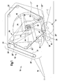
- round baler 10 includes a frame 12, a chassis 14, a drawbar 16, a receiving device 18, rollers 20, pressing elements 22, a clamping device 24, side walls 26, a baling chamber 28, pivoting parts 30 and an adjusting drive 32nd
- the round baler 10 is provided in the illustrated embodiment with a variable in size bale press room 28, but can also be provided with a size-changeable baling chamber 28.
- a size-changeable baling chamber 28 picked up from the ground crop is formed into a so-called round bale, which presses with its end faces on the side walls 26.
- the frame 12 is particularly in FIG. 2 easy to recognize and presents itself as a welding and / or screw assembly, to which all components of the round baler 10 are fixed, which is supported on the chassis 14 and which is connected to the drawbar 16 to a towing vehicle, not shown.
- the frame 12 carries, inter alia, trim parts, not shown, some of the rollers 20, the side walls 26 and the pivot parts 30.
- the frame 12 encloses the area surrounded by the side walls 26 and the pressing elements 22 area.
- the chassis 14 is in unspecified manner of an axis and wheels on which the frame 12 rests.
- the drawbar 16 engages the front of the frame 12 rigid or adjustable in height.
- the receiving device 18 is formed in the usual manner as a so-called pick-up and connected to the frame 12 height adjustable.
- the receiving device 18 may be arranged downstream of a likewise known per se cutting device.
- the receiving device 18 receives on the floor stored good and pass it on an optionally present cutting device in the baling chamber 28 where it is formed into a cylindrical round bale.
- rollers 20 are fixedly mounted rotatably in the frame 12 and are designated by 20 ', another of the rollers 20 is adjustable against the force of an unspecified spring so that the pressing elements 22 can yield to the growing bale diameter, and denoted by 20 " again other rollers 20 are pivotable on pivoting parts 30 about a pivot axis 34.
- These rollers 20 are marked 20 '''and are formed so wide, parallel to each other and arranged so that the pressing elements 22 run over it and can surround the baling chamber 28 .
- the rollers 20 are also rollers 36 are provided, which are located above an inlet opening 38 in the baling chamber 28, as so-called starter rollers work at the beginning of bale formation and on which a part of the weight of the round bale can support.
- the pressing elements 22 are formed as mutually parallel belts which substantially cover the baling chamber 28 over its width. Instead of training as a belt could also be chosen as a rod chain conveyor or as a wide band, as is also known; In this case, therefore, only one pressing element would be present, but this should also fall under the scope.
- the pressing elements 22 are endless and are thereby set in circulating motion that they rest on at least one drivable roller 20 frictionally.
- the pressing elements 22 form in the region of the inlet opening 38 a bridge which forms with increasing crop to an inwardly expanding loop and surrounds the round bale.
- the pressing elements 22 are held under tension by being guided over the position-variable roller 20 '.
- the tensioning device 24 is formed in a known manner in that the roller 20 'is guided on an arm, slide or the like, not shown, against the force of the spring and always keeps a loop of the pressing elements 22 stretched.
- the side walls 26 essentially receive in a view FIG. 1 the shape of a "D", with the back and in FIG. 1 right end portion forms an arc which follows substantially the circumferential line of the finished round bale, ie on a part of a circular arc.
- the side walls 26 are basically formed in one piece, ie they are not divided as in conventional round balers along an approximately central vertical plane; but they can be composed of several parts.
- FIG. 2 shows that the side walls 26 occupy a considerable distance to the frame 12 and thus can be deflected to the outside, as will be described below.
- the side walls 26 are rigidly formed by stiffening struts 40, wherein the stiffening struts 40 can be screwed or welded. As shown in FIG.
- the stiffening struts 40 extend almost star-shaped with respect to the pivot axis 34 and run tangentially past this at a small distance, finally to push more or less perpendicular to each other. Because of this course, they include a quadrangular chamber 42 in this embodiment .
- the side walls 26 are substantially fixedly connected to the frame 12; However, a slight pivoting movement is starting from a position according to FIG. 2 by a few degrees outward possible because either the side walls 26 in the connection area z. B. are formed of a resilient sheet, or in a resilient connection, z. B. are fixed to a resilient flange or spring-loaded screws.
- each side wall 26 is guided on an axle 44 which is rigidly secured to the frame 12 and at the same time serves as a pivot axis for the pivoting parts 30.
- the baling chamber 28 is variable in size and is at the beginning, d. H. with empty baling chamber 28, bounded by an approximately triangular cylindrical space between the receiving device 18 and the pressing means 22 and laterally from the side walls 26. With increasingly supplied crop extends the baling chamber 28 and finally takes a cross section, which follows the shape of the side walls 26 in the rear region.
- the pivoting parts 30 are provided in this embodiment on each side with one or more radially to the pivot axis 34 extending arm (s) 46 and one or more at its / its radially outer end mounted transversely extending traverse (s) 48.
- the rollers 30 ' are pivotally mounted on the axle 44 with the radially inward end of each arm 46.
- the position of the arms 46 is controlled by means of a drive 50 including a motor 52 and The motor 52 can be braked in its respective positions and holds the arms 46 correspondingly stationary
- the respective traction mechanism gears 54 associated output wheels 56 are mounted concentrically to each other and to the axis 44 and rotationally fixed with each pivotal member 30.
- the control of pivoting members 30 is such that the front pivoting member 30 is displaced during the bale formation phase to aid in the formation of a bale core and that the rearward pivot member 30 assumes a lower layer as the round bale is formed, and an upper layer when ejected
- the pivoting member 30 thus serves as a means for ejecting a finished bale into an opening position and can be restricted by the baling chamber 28.
- the lower end position of the rear pivot member 30 is in the FIG. 1 shown, while it is pivoted in its upper end position by about 180 ° upwards. It should be noted that the front pivot member 30 is not essential or could be rigidly connected to the rear pivot member 30.
- the adjusting drive 32 includes a rising and then sinking again (ie double wedge-shaped) control surface 58 and a control 60 (see FIG. 3 ) and serves for and during the ejection of the round bale to reduce the pressure and thus the friction of the side walls 26 on the end faces first, so that the round bales can be unloaded from the baling chamber 28 easier, and then increase again to decelerate it.
- the control surface 58 is located on an arc extending concentrically to the pivot axis 34 and secured to the outside of both side walls 26, although it would be sufficient to provide only a rising surface, ie on a side wall 26.
- the control surface 58 is formed of a bent steel double wedge, which is screwed uniformly sinking and rising within the chamber 42 on the side walls 26.
- Another control surface 58 ' is located farther out on a larger circular arc and secured to the outside of both side walls 26, though it would be sufficient to provide only a rising surface, ie, on a side wall 26.
- the further control surface 58 ' is formed of a bent steel double wedge, which is screwed uniformly sinking and rising within the chamber 42 on the side walls 26.
- control 60 is provided on the longitudinal center plane of the round baler 10 adjacent side of the arm 46 of the rear pivot member 30 and formed as a sliding surface. To minimize the friction, the friction surfaces are lubricated; Alternatively, the control 60 may be formed as a wheel, roller, ball or the like rotating member.
- the control element 60 is arranged in such a way that, upon rotation of the pivoting part 30 about the pivot axis 34, it describes a circular circular path and moves on the control surface 58. Preferably, the control element 60 is always in contact with the control surface 58.
- a cooperating with the further control surface 58 'control 60' is provided on the longitudinal center plane of the round baler 10 adjacent side of the arm 46 of the rear pivot member 30 in the vicinity of the radially outer end and formed as a sliding surface.
- the friction surfaces are lubricated;
- the control 60 may be formed as a wheel, roller, ball or the like rotating member.
- the further control element 60 is arranged in such a way that, upon rotation of the pivoting part 30 about the pivot axis 34, it describes a circular circular path and moves on the further control surface 58 '.
- the control element 60 is always in contact with the further control surface 58 '.
- the rear pivot member 30 is raised, whereupon, due to the pressure prevailing in the baling chamber 28 starting from the pressed crop, the side walls 26 move outwardly. As a result, the friction between the inside of the side walls 26 and the end faces of the round bale decreases and the latter begins to roll out of the baling chamber 28 due to gravity in the direction of the unloading ramp 62. Shortly thereafter, the side walls 26 are brought together again and the bale braked before it reaches the Abladerampe 62.
Landscapes
- Life Sciences & Earth Sciences (AREA)
- Environmental Sciences (AREA)
- Storage Of Harvested Produce (AREA)
Abstract
Description
- Die Erfindung betrifft eine Rundballenpresse mit einem Ballenpressraum und zum Auswerfen eines fertiggestellten Ballens in eine Öffnungsposition verbringbaren Begrenzungsmitteln des Ballenpressraums.
- Rundballenpressen finden Verwendung, um aus halmförmigem landwirtschaftlichem Erntegut Ballen herzustellen. Derartige Rundballenpressen weisen einen Ballenpressraum und zugehörige Pressmittel auf. Nach der Fertigstellung und ggf. Umwicklung eines Ballens mit Netz, Garn oder einer Folie wird dieser nach hinten aus dem Ballenpressraum ausgeworfen, nachdem eine rückwärtige Tür geöffnet wurde oder ein Ballenpresselemente haltender Schwenkteil nach oben geschwenkt wurde, um dem Ballen den Weg zu öffnen.
- Der Ballen hat beim Verlassen des Ballenpressraums einerseits noch vom Ballenbildungs- und ggf. Umwicklungsprozess eine nicht unbeträchtliche Rotationsenergie und gewinnt andererseits beim Ausrollen aus dem Ballenpressraum noch an kinetischer Energie dazu, wenn er eine rückwärtige Abladerampe der Rundballenpresse herunterrollt. Diese Bewegungsenergie kann dazu führen, dass der Ballen auf dem Erdboden unerwünscht weit rollt. Außerdem prallt er mit recht hoher Geschwindigkeit auf die Abladerampe auf, wodurch Beschädigungen des Umwicklungsmaterials auftreten können. Die Abladerampe ist daher im Stand der Technik in recht aufwändiger Weise hinreichend flexibel zu gestalten, um dieses Problem zu vermeiden.
- Im Stand der Technik (
DE 103 39 652 A1 ) wurde vorgeschlagen, an der Rückseite des Ballenpressraums der Rundballenpresse eine Tür anzubringen, die um eine vertikale oder etwa vertikale Schwenkachse schwenkbar ist und als Rückhaltevorrichtung für den Ballen dient, indem sie mit ihrer Stirnseite mit dem ausgeworfenen Ballen in Berührung kommt und ihn abbremst. Eine derartige Tür bedeutet jedoch ebenfalls einen zusätzlichen Aufwand und kann die Geschwindigkeit, mit welcher der Ballen auf die Abladerampe gelangt, nicht beeinflussen, da der Ballen erst später in Anlage an die Tür kommt. - Es sind weiterhin Rundballenpressen mit in seitlicher Richtung beweglichen Seitenwänden oder Seitenwandteilen beschrieben worden, die während der Erzeugung eines Ballens in eine innere Position verbracht und zum Auswerfen des Ballens nach außen verfahren werden, um die Reibungskräfte des Ballens während des Auswerfens zu vermindern. Hierzu sei auf die
US 4 334 467 A ,DE 39 20 377 A1 ,DE 10 2005 036 181 A1 ,EP 1 264 531 A1 ,EP 1 364 574 A1 undEP 1 396 187 A2 verwiesen. Beim Ausrollen des Ballens ist die von den Seitenwänden auf den Ballen ausgeübte Kraft somit auf einen relativ kleinen Wert vermindert, was nicht zu einer nennenswerten Bremsung des Ballens beim Ausrollen führt und das erwähnte Problem nicht löst. - Gemäß der
DE 10 2007 012 174 A1 wird die Seitenwand beim Entladevorgang in eine Position verstellt, bei der sich eine vorgegebene, sensorisch erfasste Reibung ergibt. Hier ist ein größerer Aufwand für die Regelung einschließlich eines zugehörigen Aktors zur Verstellung der Seitenwand erforderlich. Die Verstellung soll einen Austritt des Ballens sicherstellen, sodass auch hier nicht von einer nennenswerten Bremswirkung ausgegangen werden kann. - Das der Erfindung zugrunde liegende Problem wird darin gesehen, eine Rundballenpresse bereitzustellen, bei der die oben erwähnten Nachteile nicht oder in einem verminderten Maß vorliegen.
- Die vorliegende Erfindung wird durch die Patentansprüche definiert.
- Eine Rundballenpresse ist mit einem Ballenpressraum und Begrenzungsmitteln des Ballenpressraums ausgestattet, die zum Auswerfen eines fertiggestellten Ballens in eine Öffnungsposition verbringbar sind. Die axiale Abmessung des Ballenpressraums ist durch wenigstens eine mittels eines Verstelltriebs verstellbare Seitenwand veränderbar. Der Verstelltrieb ist derart konfiguriert, dass die axiale Abmessung des Ballenpressraums während des Auswerfens des Ballens gegenüber der beim Erzeugen des Ballens vorgesehenen Abmessung zunächst vergrößert und anschließend (noch während des Auswerfens des Ballens) wieder vermindert wird.
- Auf diese Weise erreicht man, dass die Klemmkraft der Seitenwand auf den Ballen während des Auswerfens zunächst gegenüber der Klemmkraft beim Erzeugen des Ballens vermindert und dann wieder vergrößert wird. Somit kann der Ballen zunächst ohne größere Bremsung seine Ausrollbewegung aus dem Ballenpressraum beginnen, ohne im Ballenpressraum stecken zu bleiben, und er wird anschließend durch die Seitenwand abgebremst. Dadurch ist eine Beschädigung des Wickelmaterials beim Herunterrollen der Abladerampe nicht mehr oder in vermindertem Maße zu befürchten, was es ermöglicht, die Abladerampe einfacher als bisher zu gestalten. Außerdem rollt der Ballen nicht mehr allzu weit von der Rundballenpresse fort.
- Der Verstellantrieb kann mit den Begrenzungsmitteln gekoppelt sein, d.h. durch diese gesteuert werden, sodass die Position der Seitenwand von der Position der Begrenzungsmittel abhängt, die wiederum die Position des Ballens vorgeben. Es wäre jedoch auch denkbar, den Verstellantrieb direkt abhängig von der mittels eines Sensors erfassten Position des Ballens zu kontrollieren.
- Die Kopplung zwischen den Begrenzungsmitteln und dem Verstelltrieb kann auf beliebige Weise erfolgen, z.B. durch eine mechanische Kopplung, wie sie im Folgenden beschrieben wird, oder durch eine elektronische Kopplung zwischen einem Aktor zur Verstellung der Begrenzungsmittel einerseits und einem Aktor zur Betätigung des Verstelltriebs andererseits, analog zu
DE 10 2007 012 174 A1 . In diesem Fall kann der Aktor den Verstelltrieb derart steuern, dass die Seitenwand eine von der Position der Begrenzungsmittel abhängige Position einnimmt oder eine davon abhängige, sensorisch erfasste Reibungskraft auf den Ballen ausübt. - Insbesondere können die Begrenzungsmittel einen Schwenkteil umfassen, welcher Mittel zur Bildung eines Ballens im Ballenpressraum trägt und zwischen einer Ballenbildungsposition und einer Ballenauswurfposition drehbeweglich ist. Bei einer anderen Ausführungsform können die Begrenzungsmittel auch als Tür (vgl.
US 4 334 467 A1 ) ausgeführt sein. - Der Schwenkteil ist vorzugsweise im Abstand von seiner Drehachse mit einem Steuerelement verbunden, das mit einer doppelkeilförmigen Steuerfläche der Seitenwand zusammenwirkt. Es können auch mehrere Steuerelemente und Steuerflächen vorhanden sein, die in unterschiedlichen Abständen von der Drehachse des Schwenkteils angeordnet sind.
- In den Zeichnungen ist ein nachfolgend näher beschriebenes Ausführungsbeispiel der Erfindung dargestellt. Es zeigt:
- Fig. 1
- eine erfindungsgemäße Rundballenpresse in Seitenansicht in einer geschlossenen Stellung und schematischer Darstellung,
- Fig. 2
- die Rundballenpresse nach
Figur 1 in einer Ansicht von hinten und in schematischer Darstellung und - Fig. 3
- eine vergrößerte Darstellung des inneren Verstelltriebs 32.
- Eine in der
Figur 1 gezeigte Rundballenpresse 10 enthält einen Rahmen 12, ein Fahrgestell 14, eine Deichsel 16, eine Aufnahmevorrichtung 18, Rollen 20, Presselemente 22, eine Spannvorrichtung 24, Seitenwände 26, einen Ballenpressraum 28, Schwenkteile 30 und einen Verstelltrieb 32. - Die Rundballenpresse 10 ist in dem dargestellten Ausführungsbeispiel mit einem in der Größe veränderbaren Ballenpressraum 28 versehen, kann aber auch mit einem größenunveränderlichen Ballenpressraum 28 versehen werden. In dem Ballenpressraum 28 wird vom Boden aufgenommenes Erntegut zu einem sogenannten Rundballen geformt, der mit seinen Stirnseiten auf die Seitenwände 26 drückt.
- Der Rahmen 12 ist insbesondere in
Figur 2 gut zu erkennen und stellt sich als ein Schweiß- und/oder Schraubzusammenbau dar, an dem alle Komponenten der Rundballenpresse 10 befestigt sind, der sich auf dem Fahrgestell 14 abstützt und der mit der Deichsel 16 an ein nicht gezeigtes Zugfahrzeug anschließbar ist. Der Rahmen 12 trägt unter anderem nicht dargestellte Verkleidungsteile, einige der Rollen 20, die Seitenwände 26 und die Schwenkteile 30. Der Rahmen 12 umschließt den von den Seitenwänden 26 und den Presselementen 22 umgebenen Bereich weiträumig. - Das Fahrgestell 14 besteht in nicht näher bezeichneter Weise aus einer Achse und Rädern, auf denen der Rahmen 12 ruht. Die Deichsel 16 greift an der Vorderseite des Rahmens 12 starr oder höhenverstellbar an. Die Aufnahmevorrichtung 18 ist in üblicher Weise als eine so genannte Pick-up ausgebildet und an den Rahmen 12 höhenverstellbar angeschlossen. Der Aufnahmevorrichtung 18 kann eine ebenfalls an sich bekannte Schneidvorrichtung nachgeordnet werden. Die Aufnahmevorrichtung 18 nimmt auf dem Boden abgelegtes Gut auf und gibt es über eine gegebenenfalls vorhandene Schneidvorrichtung in den Ballenpressraum 28 weiter, wo es zu einem zylindrischen Rundballen geformt wird.
- Einige der Rollen 20 sind ortsfest in dem Rahmen 12 drehbar gelagert und werden mit 20' bezeichnet, eine andere der Rollen 20 ist gegen die Kraft einer nicht näher bezeichneten Feder verstellbar, damit die Presselemente 22 dem wachsenden Ballendurchmesser nachgeben können, und mit 20" bezeichnet; wieder andere Rollen 20 sind auf Schwenkteilen 30 um eine Schwenkachse 34 schwenkbar. Diese Rollen 20 werden mit 20'" gekennzeichnet und sind derart breit ausgebildet, verlaufen zueinander parallel und sind so angeordnet, dass die Presselemente 22 darüber ablaufen und den Ballenpressraum 28 umschließen können. Neben den Rollen 20 sind auch Walzen 36 vorgesehen, die sich oberhalb einer Eingangsöffnung 38 in den Ballenpressraum 28 befinden, als sogenannte Starterrollen beim Ballenbildungsbeginn funktionieren und auf denen sich ein Teil des Gewichts des Rundballens abstützen kann.
- Die Presselemente 22 sind als parallel zueinander verlaufende Riemen ausgebildet, die den Ballenpressraum 28 auf seiner Breite im Wesentlichen bedecken. Statt der Ausbildung als Riemen könnte auch eine als Stabkettenförderer oder als breites Band gewählt werden, wie dies ebenfalls bekannt ist; in diesem Fall wäre also nur ein Presselement vorhanden, was aber ebenfalls unter den Schutzbereich fallen soll. Die Presselemente 22 sind endlos und werden dadurch in Umlaufbewegung versetzt, dass sie reibschlüssig auf wenigstens einer antreibbaren Rolle 20 aufliegen. Die Presselemente 22 bilden im Bereich der Eingangsöffnung 38 eine Brücke, die sich mit zunehmendem Erntegut zu einer nach innen ausweitenden Schlaufe formt und den Rundballen umgibt. Die Presselemente 22 werden dadurch unter Spannung gehalten, dass sie über die lageveränderliche Rolle 20' geführt werden.
- Die Spannvorrichtung 24 wird in bekannter Weise dadurch gebildet, dass die Rolle 20' auf einem nicht dargestellten Arm, Schlitten oder dergleichen gegen die Kraft der Feder geführt ist und stets eine Schlaufe der Presselemente 22 gespannt hält.
- Die Seitenwände 26 nehmen im Wesentlichen in einer Ansicht auf
Figur 1 die Form eines "D" ein, wobei der rückwärtige und inFigur 1 rechte Endbereich einen Bogen bildet, der im Wesentlichen der Umfangslinie des fertigen Rundballens folgt, d. h. auf einem Teil eines runden Kreisbogens. Die Seitenwände 26 sind grundsätzlich einstückig ausgebildet, d.h. sie sind nicht wie bei herkömmlichen Rundballenpressen entlang einer etwa mittigen vertikalen Ebene geteilt; sie können aber durchaus aus mehreren Teilen zusammengesetzt werden. AusFigur 2 geht hervor, dass die Seitenwände 26 einen nicht unbeträchtlichen Abstand zu dem Rahmen 12 einnehmen und somit nach außen ausgelenkt werden können, wie dies nachfolgend beschrieben wird. Die Seitenwände 26 sind mittels Versteifungsstreben 40 biegesteif ausgebildet, wobei die Versteifungsstreben 40 aufgeschraubt oder aufgeschweißt werden können. Gemäß der Darstellung inFigur 2 verlaufen die Versteifungsstreben 40 nahezu sternförmig mit Bezug auf die Schwenkachse 34 und verlaufen tangential an dieser mit geringem Abstand vorbei, um schließlich mehr oder weniger senkrecht aufeinander zu stoßen. Aufgrund dieses Verlaufs schließen sie eine in diesem Ausführungsbeispiel viereckige Kammer 42 ein. In ihrem vorderen Endbereich sind die Seitenwände 26 mit dem Rahmen 12 im Wesentlichen fest verbunden; allerdings ist eine geringe Schwenkbewegung ausgehend von einer Lage gemäßFigur 2 um wenige Grade nach außen dadurch möglich, dass entweder die Seitenwände 26 im Anschlussbereich z. B. aus einem nachgiebigen Blech gebildet sind, oder in einer nachgiebigen Verbindung, z. B. an einem nachgiebigen Flansch oder an federbelasteten Schrauben festgelegt sind. Der Anschluss der Seitenwände 26 an dem Rahmen 12 erfolgt um wesentlichen entlang einer mehr oder weniger vertikalen Linie am vorderen Ende des Ballenpressraums 28. Im Bereich der Schwenkachse 34 ist jede Seitenwand 26 auf einer Achse 44 geführt, die an dem Rahmen 12 starr befestigt ist und zugleich als Schwenkachse für die Schwenkteile 30 dient. - Der Ballenpressraum 28 ist in seiner Größe veränderlich und wird am Anfang, d. h. bei leerem Ballenpressraum 28, von einem ungefähr dreieckigen zylindrischen Raum zwischen der Aufnahmevorrichtung 18 und dem Pressmittel 22 und seitlich von den Seitenwänden 26 begrenzt. Mit zunehmend zugeführtem Erntegut erweitert sich der Ballenpressraum 28 und nimmt schließlich einen Querschnitt ein, der im rückwärtigen Bereich der Form der Seitenwände 26 folgt.
- Die Schwenkteile 30 sind in diesem Ausführungsbeispiel auf jeder Seite mit einem oder mehreren radial zu der Schwenkachse 34 verlaufenden Arm(en) 46 und einer oder mehreren an dessen/deren radial außen liegenden Ende angebrachten quer dazu verlaufenden Traverse(n) 48 versehen. Am Ende jeder Traverse 48 ist jeweils eine Rolle 20'" vorgesehen. Die Schwenkteile 30 sind mit dem radial innenliegenden Ende jedes Arms 46 schwenkbar auf der Achse 44 angeordnet. Die Stellung der Arme 46 wird mittels eines Antriebs 50 gesteuert, der einen Motor 52 und pro Schwenkteil 30 ein Zugmittelgetriebe 54 oder einen sonstigen Schwenkantrieb enthält. Der Motor 52 kann in seinen jeweiligen Stellungen gebremst werden und hält die Arme 46 entsprechend ortsfest. Den jeweiligen Zugmittelgetrieben 54 zugehörige Abtriebsräder 56 sind konzentrisch zueinander und zu der Achse 44 gelagert und drehfest mit jeweils einem Schwenkteil 30 verbunden. Die Steuerung der Schwenkteile 30 erfolgt derart, dass der vordere Schwenkteil 30 während der Ballenbildungsphase verstellt wird, um bei der Bildung eines Ballenkerns zu helfen, und dass der rückwärtige Schwenkteil 30 eine untere Lage einnimmt, während der Rundballen gebildet wird, und eine oberen Lage, wenn er ausgeworfen wird. Der rückwärtige Schwenkteil 30 dient somit als zum Auswerfen eines fertiggestellten Ballens in eine Öffnungsposition verbringbares Begrenzungsmittel des Ballenpressraums 28. Die untere Endlage des rückwärtigen Schwenkteils 30 ist in der
Figur 1 dargestellt, während er in seiner oberen Endlage um ca. 180° nach oben verschwenkt ist. Es wird darauf hingewiesen, dass der vordere Schwenkteil 30 nicht unbedingt erforderlich ist oder starr mit dem hinteren Schwenkteil 30 verbunden werden könnte. - Der Verstelltrieb 32 enthält eine ansteigende und anschließend wieder absinkende (d.h. doppelkeilförmige) Steuerfläche 58 und ein Steuerelement 60 (vgl. die
Figur 3 ) und dient dazu, zum und beim Auswerfen des Rundballens den Druck und damit die Reibung der Seitenwände 26 auf dessen Stirnflächen zunächst zu verringern, so dass der Rundballen leichter aus dem Ballenpressraum 28 entladen werden kann, und dann wieder zu vergrößern, um ihn abzubremsen. - Die Steuerfläche 58 ist auf einem zu der Schwenkachse 34 konzentrisch verlaufenden Kreisbogen gelegen und an der Außenseite beider Seitenwände 26 befestigt, wenn es auch ausreichend wäre, nur eine ansteigende Fläche, d. h. an einer Seitenwand 26 vorzusehen. In dem vorliegenden Ausführungsbeispiel ist die Steuerfläche 58 aus einem gebogenen Stahldoppelkeil gebildet, der gleichmäßig sinkend und ansteigend innerhalb der Kammer 42 auf die Seitenwände 26 aufgeschraubt ist.
- Eine weitere Steuerfläche 58' ist weiter außen auf einem größeren Kreisbogen gelegen und an der Außenseite beider Seitenwände 26 befestigt, wenn es auch ausreichend wäre, nur eine ansteigende Fläche, d. h. an einer Seitenwand 26 vorzusehen. In dem vorliegenden Ausführungsbeispiel ist die weitere Steuerfläche 58' aus einem gebogenen Stahldoppelkeil gebildet, der gleichmäßig sinkend und ansteigend innerhalb der Kammer 42 auf die Seitenwände 26 aufgeschraubt ist.
- Das mit der Steuerfläche 58 zusammenwirkende Steuerelement 60 ist auf der der Längsmittenebene der Rundballenpresse 10 zugelegenen Seite des Arms 46 des rückwärtigen Schwenkteils 30 vorgesehen und als Gleitfläche ausgebildet. Zur Minimierung der Reibung werden die Reibflächen geschmiert; alternativ kann das Steuerelement 60 auch als Rad, Rolle, Kugel oder dergleichen drehendes Glied ausgebildet werden. Das Steuerelement 60 ist derart angeordnet, dass es bei einer Drehung des Schwenkteils 30 um die Schwenkachse 34 eine runde Kreisbahn beschreibt und sich auf der Steuerfläche 58 bewegt. Vorzugsweisen befindet sich das Steuerelement 60 stets in Anlage auf der Steuerfläche 58.
- Ein mit der weiteren Steuerfläche 58' zusammenwirkendes Steuerelement 60' ist auf der der Längsmittenebene der Rundballenpresse 10 zugelegenen Seite des Arms 46 des rückwärtigen Schwenkteils 30 in der Nähe von dessen radial äußerem Ende vorgesehen und als Gleitfläche ausgebildet. Zur Minimierung der Reibung werden die Reibflächen geschmiert; alternativ kann das Steuerelement 60 auch als Rad, Rolle, Kugel oder dergleichen drehendes Glied ausgebildet werden. Das weitere Steuerelement 60 ist derart angeordnet, dass es bei einer Drehung des Schwenkteils 30 um die Schwenkachse 34 eine runde Kreisbahn beschreibt und sich auf der weiteren Steuerfläche 58' bewegt. Vorzugsweisen befindet sich das Steuerelement 60 stets in Anlage auf der weiteren Steuerfläche 58'.
- Die Steuerelemente 60, 60' liegen auf der höchsten Erhebung der Steuerflächen 58, 58' auf, wenn sich die rückwärtigen Schwenkteile 30 in ihrer unteren Endstellung befinden - vgl.
Figur 1 - und der Rundballen erzeugt werden kann. Wenn die Schwenkteile 30 in ihre mittige Stellung gebracht werden, in der der Rundballen seine Bewegung aus dem Ballenpressraum 28 beginnt, werden die Steuerelement 60, 60' zu der niedrigsten Stelle der Steuerflächen 58, 58' bewegt. Wenn die Schwenkteile 30 in ihre obere Stellung gebracht werden, in der der Rundballen seine Bewegung aus dem Ballenpressraum 28 fortsetzt und den Ballenpressraum 28 verlässt, werden die Steuerelemente 60, 60' zu einer wieder höheren Stelle der ansteigenden Steuerflächen 58, 58' bewegt, deren Höhe mit der unteren Schwenkstellung übereinstimmen oder etwas kleiner oder sogar größer sein kann, um den Ballen abzubremsen, bevor dieser eine Abladerampe 62 erreicht. - Sobald in dem Ballenpressraum 28 ein Rundballen gebildet ist, wird der rückwärtige Schwenkteil 30 angehoben, worauf sich aufgrund des in dem Ballenpressraum 28 herrschenden Drucks ausgehend von dem gepressten Erntegut die Seitenwände 26 nach außen bewegen. Infolgedessen verringert sich die Reibung zwischen der Innenseite der Seitenwände 26 und den Stirnflächen des Rundballens und letzterer beginnt aufgrund der Schwerkraft in Richtung auf die Abladerampe 62 hin aus dem Ballenpressraum 28 herauszurollen. Kurz danach werden die Seitenwände 26 wieder zusammengeführt und der Ballen abgebremst, bevor dieser die Abladerampe 62 erreicht. Sobald der Rundballen den Ballenpressraum 28 komplett verlassen hat und die Rundballenpresse 10 soweit weiterbewegt worden ist, dass der rückwärtige Schwenkteil 30 wieder abgesenkt werden kann, erfolgt eine Schwenkbewegung des rückwärtigen Schwenkteils 30 in der entgegensetzten Richtung, so dass die Steuerelement 60', 60' zur kleinsten und schließlich zur größten Erhebung der ansteigenden Flächen 58, 58 bewegt werden und dabei die Seitenwände 26 nach außen und dann nach innen drückt und ein neuer Ballen erstellt werden kann.
Claims (5)
- Rundballenpresse (10) mit einem Ballenpressraum (28) und zum Auswerfen eines fertiggestellten Ballens in eine Öffnungsposition verbringbaren Begrenzungsmitteln des Ballenpressraums (28), wobei:die axiale Abmessung des Ballenpressraums (28) durch wenigstens eine mittels eines Verstelltriebs (32) verstellbare Seitenwand (26) veränderbar ist,und der Verstelltrieb (32) derart konfiguriert ist, dass die axiale Abmessung des Ballenpressraums (28) während des Auswerfens des Ballens gegenüber der beim Erzeugen des Ballens vorgesehenen Abmessung zunächst vergrößert und anschließend während des Auswerfens wieder vermindert wird.
- Rundballenpresse (10) nach Anspruch 1, wobei der Verstellantrieb (32) mit den Begrenzungsmitteln gekoppelt ist.
- Rundballenpresse (10) nach Anspruch 2, wobei die Begrenzungsmittel einen Schwenkteil (30) umfassen, welcher Mittel zur Bildung eines Ballens im Ballenpressraum (28) trägt und zwischen einer Ballenbildungsposition und einer Ballenauswurfposition drehbeweglich ist.
- Rundballenpresse (10) nach Anspruch 3, wobei der Schwenkteil (30) im Abstand von seiner Drehachse (34) mit einem Steuerelement (60, 60') verbunden ist, das mit einer doppelkeilförmigen Steuerfläche (58, 58') der Seitenwand (28) zusammenwirkt.
- Rundballenpresse (10) nach Anspruch 4, wobei mehrere Steuerelemente (60, 60') und Steuerflächen (58, 58') vorhanden sind, die in unterschiedlichen Abständen von der Drehachse (34) des Schwenkteils (30) angeordnet sind.
Applications Claiming Priority (1)
| Application Number | Priority Date | Filing Date | Title |
|---|---|---|---|
| DE102015210998.4A DE102015210998A1 (de) | 2015-06-16 | 2015-06-16 | Rundballenpresse |
Publications (2)
| Publication Number | Publication Date |
|---|---|
| EP3106021A1 true EP3106021A1 (de) | 2016-12-21 |
| EP3106021B1 EP3106021B1 (de) | 2020-01-29 |
Family
ID=56087183
Family Applications (1)
| Application Number | Title | Priority Date | Filing Date |
|---|---|---|---|
| EP16171873.9A Active EP3106021B1 (de) | 2015-06-16 | 2016-05-30 | Rundballenpresse |
Country Status (3)
| Country | Link |
|---|---|
| US (1) | US9706717B2 (de) |
| EP (1) | EP3106021B1 (de) |
| DE (1) | DE102015210998A1 (de) |
Families Citing this family (3)
| Publication number | Priority date | Publication date | Assignee | Title |
|---|---|---|---|---|
| US11382275B2 (en) | 2016-08-31 | 2022-07-12 | Tube-Line Manufacturing Limited | Continuous round baler accumulation chamber |
| US10813291B2 (en) * | 2017-10-02 | 2020-10-27 | Deere & Company | Round baler having an adjustable width |
| DE102022113276A1 (de) * | 2022-05-25 | 2023-11-30 | Usines Claas France S.A.S | Landwirtschaftliche Ballenpresse mit einer Spanneinrichtung für einen Zugmitteltrieb |
Citations (9)
| Publication number | Priority date | Publication date | Assignee | Title |
|---|---|---|---|---|
| US4334467A (en) | 1979-06-22 | 1982-06-15 | Farmhand Inc. | Rotary baler with side pressure release |
| DE3920377A1 (de) | 1989-06-22 | 1991-01-17 | Welger Geb | Rollballenpresse fuer landwirtschaftliche halmgueter |
| EP1264531A1 (de) | 2001-06-06 | 2002-12-11 | Deere & Company | Rundballenpresse |
| EP1364574A1 (de) | 2002-05-23 | 2003-11-26 | Deere & Company | Rundballenpresse |
| EP1396187A2 (de) | 2002-09-06 | 2004-03-10 | Deere & Company | Rundballenpresse mit Wägeeinrichtung |
| DE10339652A1 (de) | 2003-08-28 | 2005-05-19 | Deere & Company, Moline | Rundballenpresse |
| DE102005036181A1 (de) | 2005-08-02 | 2007-02-15 | Deere & Company, Moline | Rundballenpresse |
| EP1969918A1 (de) * | 2007-03-14 | 2008-09-17 | Deere & Company | Rundballenpresse und Verfahren zur Änderung der Reibung an deren Seitenwänden |
| WO2014194287A2 (en) * | 2013-05-30 | 2014-12-04 | Cnh Industrial America Llc | Bale eject linkage and methods of use |
Family Cites Families (1)
| Publication number | Priority date | Publication date | Assignee | Title |
|---|---|---|---|---|
| US4370848A (en) * | 1981-09-24 | 1983-02-01 | Sperry Corporation | Baling machine with tapered bale chamber |
-
2015
- 2015-06-16 DE DE102015210998.4A patent/DE102015210998A1/de not_active Withdrawn
-
2016
- 2016-05-30 EP EP16171873.9A patent/EP3106021B1/de active Active
- 2016-06-14 US US15/182,077 patent/US9706717B2/en active Active
Patent Citations (10)
| Publication number | Priority date | Publication date | Assignee | Title |
|---|---|---|---|---|
| US4334467A (en) | 1979-06-22 | 1982-06-15 | Farmhand Inc. | Rotary baler with side pressure release |
| DE3920377A1 (de) | 1989-06-22 | 1991-01-17 | Welger Geb | Rollballenpresse fuer landwirtschaftliche halmgueter |
| EP1264531A1 (de) | 2001-06-06 | 2002-12-11 | Deere & Company | Rundballenpresse |
| EP1364574A1 (de) | 2002-05-23 | 2003-11-26 | Deere & Company | Rundballenpresse |
| EP1396187A2 (de) | 2002-09-06 | 2004-03-10 | Deere & Company | Rundballenpresse mit Wägeeinrichtung |
| DE10339652A1 (de) | 2003-08-28 | 2005-05-19 | Deere & Company, Moline | Rundballenpresse |
| DE102005036181A1 (de) | 2005-08-02 | 2007-02-15 | Deere & Company, Moline | Rundballenpresse |
| EP1969918A1 (de) * | 2007-03-14 | 2008-09-17 | Deere & Company | Rundballenpresse und Verfahren zur Änderung der Reibung an deren Seitenwänden |
| DE102007012174A1 (de) | 2007-03-14 | 2008-12-24 | Deere & Company, Moline | Rundballenpresse und Verfahren zur Änderung der Reibung an deren Seitenwänden |
| WO2014194287A2 (en) * | 2013-05-30 | 2014-12-04 | Cnh Industrial America Llc | Bale eject linkage and methods of use |
Also Published As
| Publication number | Publication date |
|---|---|
| US20160366831A1 (en) | 2016-12-22 |
| DE102015210998A1 (de) | 2016-12-22 |
| EP3106021B1 (de) | 2020-01-29 |
| US9706717B2 (en) | 2017-07-18 |
Similar Documents
| Publication | Publication Date | Title |
|---|---|---|
| EP1396187B1 (de) | Rundballenpresse mit Wägeeinrichtung | |
| EP1157603B1 (de) | Vorrichtung zum Umhüllen eines Rundballens | |
| EP1364574B1 (de) | Rundballenpresse | |
| EP1795065B1 (de) | Ballenpresse mit einer Feuchtemesseinrichtung | |
| EP1969918B1 (de) | Rundballenpresse und Verfahren zur Änderung der Reibung an deren Seitenwänden | |
| DE202007018801U1 (de) | Vorrichtung zum Verpacken von Reifen | |
| DE10339652A1 (de) | Rundballenpresse | |
| DE19959574B4 (de) | Ballenpresse | |
| EP1438889A1 (de) | Presse, insbesondere Rundballenpresse | |
| EP1407657A2 (de) | Kombination einer Rundballenpresse mit einem Wickelgerät | |
| EP2984922B1 (de) | Ballenwickeleinrichtung | |
| DE102016215085A1 (de) | Ballenwickeleinrichtung für eine Rundballenpresse, Rundballenpresse und Verfahren zum Betreiben einer solchen | |
| EP3106021B1 (de) | Rundballenpresse | |
| DE10153539A1 (de) | Rundballenpresse | |
| EP1344448B1 (de) | Rundballenpresse | |
| EP2550853B1 (de) | Rundballenpresse | |
| EP2550854B1 (de) | Rundballenpresse | |
| DE102015211035A1 (de) | Rundballenpresse mit einem Sensor zur Erfassung der Ballengröße | |
| DE10153540A1 (de) | Rundballenpresse | |
| DE102016221104A1 (de) | Rundballenpresse, Kombination eines landwirtschaftlichen Fahrzeugs mit einer solchen und Verfahren zum Pressen von Rundballen | |
| DE202005008468U1 (de) | Vorrichtung zum Pressen und Umhüllen von Rundballen | |
| EP3028561B1 (de) | Festkammerpresse | |
| EP1446998A1 (de) | Vorrichtung zum Unterstützen des Austritts eines Rundballens | |
| DE102005036181B4 (de) | Rundballenpresse | |
| DE102019135610A1 (de) | Vorrichtung und Verfahren zum Verarbeiten eines Polstermaterialstrangs und Polstermaterialwicklung |
Legal Events
| Date | Code | Title | Description |
|---|---|---|---|
| PUAI | Public reference made under article 153(3) epc to a published international application that has entered the european phase |
Free format text: ORIGINAL CODE: 0009012 |
|
| STAA | Information on the status of an ep patent application or granted ep patent |
Free format text: STATUS: THE APPLICATION HAS BEEN PUBLISHED |
|
| AK | Designated contracting states |
Kind code of ref document: A1 Designated state(s): AL AT BE BG CH CY CZ DE DK EE ES FI FR GB GR HR HU IE IS IT LI LT LU LV MC MK MT NL NO PL PT RO RS SE SI SK SM TR |
|
| AX | Request for extension of the european patent |
Extension state: BA ME |
|
| STAA | Information on the status of an ep patent application or granted ep patent |
Free format text: STATUS: REQUEST FOR EXAMINATION WAS MADE |
|
| 17P | Request for examination filed |
Effective date: 20170621 |
|
| RBV | Designated contracting states (corrected) |
Designated state(s): AL AT BE BG CH CY CZ DE DK EE ES FI FR GB GR HR HU IE IS IT LI LT LU LV MC MK MT NL NO PL PT RO RS SE SI SK SM TR |
|
| GRAP | Despatch of communication of intention to grant a patent |
Free format text: ORIGINAL CODE: EPIDOSNIGR1 |
|
| STAA | Information on the status of an ep patent application or granted ep patent |
Free format text: STATUS: GRANT OF PATENT IS INTENDED |
|
| INTG | Intention to grant announced |
Effective date: 20190913 |
|
| GRAS | Grant fee paid |
Free format text: ORIGINAL CODE: EPIDOSNIGR3 |
|
| GRAA | (expected) grant |
Free format text: ORIGINAL CODE: 0009210 |
|
| STAA | Information on the status of an ep patent application or granted ep patent |
Free format text: STATUS: THE PATENT HAS BEEN GRANTED |
|
| AK | Designated contracting states |
Kind code of ref document: B1 Designated state(s): AL AT BE BG CH CY CZ DE DK EE ES FI FR GB GR HR HU IE IS IT LI LT LU LV MC MK MT NL NO PL PT RO RS SE SI SK SM TR |
|
| REG | Reference to a national code |
Ref country code: GB Ref legal event code: FG4D Free format text: NOT ENGLISH |
|
| REG | Reference to a national code |
Ref country code: CH Ref legal event code: EP |
|
| REG | Reference to a national code |
Ref country code: AT Ref legal event code: REF Ref document number: 1227818 Country of ref document: AT Kind code of ref document: T Effective date: 20200215 |
|
| REG | Reference to a national code |
Ref country code: IE Ref legal event code: FG4D Free format text: LANGUAGE OF EP DOCUMENT: GERMAN |
|
| REG | Reference to a national code |
Ref country code: DE Ref legal event code: R096 Ref document number: 502016008499 Country of ref document: DE |
|
| REG | Reference to a national code |
Ref country code: SE Ref legal event code: TRGR |
|
| REG | Reference to a national code |
Ref country code: NL Ref legal event code: MP Effective date: 20200129 |
|
| PG25 | Lapsed in a contracting state [announced via postgrant information from national office to epo] |
Ref country code: PT Free format text: LAPSE BECAUSE OF FAILURE TO SUBMIT A TRANSLATION OF THE DESCRIPTION OR TO PAY THE FEE WITHIN THE PRESCRIBED TIME-LIMIT Effective date: 20200621 Ref country code: FI Free format text: LAPSE BECAUSE OF FAILURE TO SUBMIT A TRANSLATION OF THE DESCRIPTION OR TO PAY THE FEE WITHIN THE PRESCRIBED TIME-LIMIT Effective date: 20200129 Ref country code: NO Free format text: LAPSE BECAUSE OF FAILURE TO SUBMIT A TRANSLATION OF THE DESCRIPTION OR TO PAY THE FEE WITHIN THE PRESCRIBED TIME-LIMIT Effective date: 20200429 Ref country code: RS Free format text: LAPSE BECAUSE OF FAILURE TO SUBMIT A TRANSLATION OF THE DESCRIPTION OR TO PAY THE FEE WITHIN THE PRESCRIBED TIME-LIMIT Effective date: 20200129 |
|
| REG | Reference to a national code |
Ref country code: LT Ref legal event code: MG4D |
|
| PG25 | Lapsed in a contracting state [announced via postgrant information from national office to epo] |
Ref country code: GR Free format text: LAPSE BECAUSE OF FAILURE TO SUBMIT A TRANSLATION OF THE DESCRIPTION OR TO PAY THE FEE WITHIN THE PRESCRIBED TIME-LIMIT Effective date: 20200430 Ref country code: IS Free format text: LAPSE BECAUSE OF FAILURE TO SUBMIT A TRANSLATION OF THE DESCRIPTION OR TO PAY THE FEE WITHIN THE PRESCRIBED TIME-LIMIT Effective date: 20200529 Ref country code: HR Free format text: LAPSE BECAUSE OF FAILURE TO SUBMIT A TRANSLATION OF THE DESCRIPTION OR TO PAY THE FEE WITHIN THE PRESCRIBED TIME-LIMIT Effective date: 20200129 Ref country code: LV Free format text: LAPSE BECAUSE OF FAILURE TO SUBMIT A TRANSLATION OF THE DESCRIPTION OR TO PAY THE FEE WITHIN THE PRESCRIBED TIME-LIMIT Effective date: 20200129 Ref country code: BG Free format text: LAPSE BECAUSE OF FAILURE TO SUBMIT A TRANSLATION OF THE DESCRIPTION OR TO PAY THE FEE WITHIN THE PRESCRIBED TIME-LIMIT Effective date: 20200429 |
|
| PG25 | Lapsed in a contracting state [announced via postgrant information from national office to epo] |
Ref country code: NL Free format text: LAPSE BECAUSE OF FAILURE TO SUBMIT A TRANSLATION OF THE DESCRIPTION OR TO PAY THE FEE WITHIN THE PRESCRIBED TIME-LIMIT Effective date: 20200129 |
|
| PG25 | Lapsed in a contracting state [announced via postgrant information from national office to epo] |
Ref country code: DK Free format text: LAPSE BECAUSE OF FAILURE TO SUBMIT A TRANSLATION OF THE DESCRIPTION OR TO PAY THE FEE WITHIN THE PRESCRIBED TIME-LIMIT Effective date: 20200129 Ref country code: LT Free format text: LAPSE BECAUSE OF FAILURE TO SUBMIT A TRANSLATION OF THE DESCRIPTION OR TO PAY THE FEE WITHIN THE PRESCRIBED TIME-LIMIT Effective date: 20200129 Ref country code: SM Free format text: LAPSE BECAUSE OF FAILURE TO SUBMIT A TRANSLATION OF THE DESCRIPTION OR TO PAY THE FEE WITHIN THE PRESCRIBED TIME-LIMIT Effective date: 20200129 Ref country code: EE Free format text: LAPSE BECAUSE OF FAILURE TO SUBMIT A TRANSLATION OF THE DESCRIPTION OR TO PAY THE FEE WITHIN THE PRESCRIBED TIME-LIMIT Effective date: 20200129 Ref country code: ES Free format text: LAPSE BECAUSE OF FAILURE TO SUBMIT A TRANSLATION OF THE DESCRIPTION OR TO PAY THE FEE WITHIN THE PRESCRIBED TIME-LIMIT Effective date: 20200129 Ref country code: RO Free format text: LAPSE BECAUSE OF FAILURE TO SUBMIT A TRANSLATION OF THE DESCRIPTION OR TO PAY THE FEE WITHIN THE PRESCRIBED TIME-LIMIT Effective date: 20200129 Ref country code: CZ Free format text: LAPSE BECAUSE OF FAILURE TO SUBMIT A TRANSLATION OF THE DESCRIPTION OR TO PAY THE FEE WITHIN THE PRESCRIBED TIME-LIMIT Effective date: 20200129 Ref country code: SK Free format text: LAPSE BECAUSE OF FAILURE TO SUBMIT A TRANSLATION OF THE DESCRIPTION OR TO PAY THE FEE WITHIN THE PRESCRIBED TIME-LIMIT Effective date: 20200129 |
|
| REG | Reference to a national code |
Ref country code: DE Ref legal event code: R097 Ref document number: 502016008499 Country of ref document: DE |
|
| PLBE | No opposition filed within time limit |
Free format text: ORIGINAL CODE: 0009261 |
|
| STAA | Information on the status of an ep patent application or granted ep patent |
Free format text: STATUS: NO OPPOSITION FILED WITHIN TIME LIMIT |
|
| 26N | No opposition filed |
Effective date: 20201030 |
|
| PG25 | Lapsed in a contracting state [announced via postgrant information from national office to epo] |
Ref country code: IT Free format text: LAPSE BECAUSE OF FAILURE TO SUBMIT A TRANSLATION OF THE DESCRIPTION OR TO PAY THE FEE WITHIN THE PRESCRIBED TIME-LIMIT Effective date: 20200129 Ref country code: CH Free format text: LAPSE BECAUSE OF NON-PAYMENT OF DUE FEES Effective date: 20200531 Ref country code: LI Free format text: LAPSE BECAUSE OF NON-PAYMENT OF DUE FEES Effective date: 20200531 Ref country code: MC Free format text: LAPSE BECAUSE OF FAILURE TO SUBMIT A TRANSLATION OF THE DESCRIPTION OR TO PAY THE FEE WITHIN THE PRESCRIBED TIME-LIMIT Effective date: 20200129 |
|
| PG25 | Lapsed in a contracting state [announced via postgrant information from national office to epo] |
Ref country code: PL Free format text: LAPSE BECAUSE OF FAILURE TO SUBMIT A TRANSLATION OF THE DESCRIPTION OR TO PAY THE FEE WITHIN THE PRESCRIBED TIME-LIMIT Effective date: 20200129 Ref country code: SI Free format text: LAPSE BECAUSE OF FAILURE TO SUBMIT A TRANSLATION OF THE DESCRIPTION OR TO PAY THE FEE WITHIN THE PRESCRIBED TIME-LIMIT Effective date: 20200129 |
|
| REG | Reference to a national code |
Ref country code: BE Ref legal event code: MM Effective date: 20200531 |
|
| GBPC | Gb: european patent ceased through non-payment of renewal fee |
Effective date: 20200530 |
|
| PG25 | Lapsed in a contracting state [announced via postgrant information from national office to epo] |
Ref country code: LU Free format text: LAPSE BECAUSE OF NON-PAYMENT OF DUE FEES Effective date: 20200530 |
|
| PG25 | Lapsed in a contracting state [announced via postgrant information from national office to epo] |
Ref country code: IE Free format text: LAPSE BECAUSE OF NON-PAYMENT OF DUE FEES Effective date: 20200530 Ref country code: GB Free format text: LAPSE BECAUSE OF NON-PAYMENT OF DUE FEES Effective date: 20200530 |
|
| PG25 | Lapsed in a contracting state [announced via postgrant information from national office to epo] |
Ref country code: BE Free format text: LAPSE BECAUSE OF NON-PAYMENT OF DUE FEES Effective date: 20200531 |
|
| PG25 | Lapsed in a contracting state [announced via postgrant information from national office to epo] |
Ref country code: TR Free format text: LAPSE BECAUSE OF FAILURE TO SUBMIT A TRANSLATION OF THE DESCRIPTION OR TO PAY THE FEE WITHIN THE PRESCRIBED TIME-LIMIT Effective date: 20200129 Ref country code: MT Free format text: LAPSE BECAUSE OF FAILURE TO SUBMIT A TRANSLATION OF THE DESCRIPTION OR TO PAY THE FEE WITHIN THE PRESCRIBED TIME-LIMIT Effective date: 20200129 Ref country code: CY Free format text: LAPSE BECAUSE OF FAILURE TO SUBMIT A TRANSLATION OF THE DESCRIPTION OR TO PAY THE FEE WITHIN THE PRESCRIBED TIME-LIMIT Effective date: 20200129 |
|
| PG25 | Lapsed in a contracting state [announced via postgrant information from national office to epo] |
Ref country code: MK Free format text: LAPSE BECAUSE OF FAILURE TO SUBMIT A TRANSLATION OF THE DESCRIPTION OR TO PAY THE FEE WITHIN THE PRESCRIBED TIME-LIMIT Effective date: 20200129 Ref country code: AL Free format text: LAPSE BECAUSE OF FAILURE TO SUBMIT A TRANSLATION OF THE DESCRIPTION OR TO PAY THE FEE WITHIN THE PRESCRIBED TIME-LIMIT Effective date: 20200129 |
|
| REG | Reference to a national code |
Ref country code: AT Ref legal event code: MM01 Ref document number: 1227818 Country of ref document: AT Kind code of ref document: T Effective date: 20210530 |
|
| PG25 | Lapsed in a contracting state [announced via postgrant information from national office to epo] |
Ref country code: AT Free format text: LAPSE BECAUSE OF NON-PAYMENT OF DUE FEES Effective date: 20210530 |
|
| PGFP | Annual fee paid to national office [announced via postgrant information from national office to epo] |
Ref country code: DE Payment date: 20250423 Year of fee payment: 10 |
|
| PGFP | Annual fee paid to national office [announced via postgrant information from national office to epo] |
Ref country code: FR Payment date: 20250526 Year of fee payment: 10 |
|
| PGFP | Annual fee paid to national office [announced via postgrant information from national office to epo] |
Ref country code: SE Payment date: 20250527 Year of fee payment: 10 |