EP3104820B1 - Collapsible wheeled support or carrier - Google Patents
Collapsible wheeled support or carrier Download PDFInfo
- Publication number
- EP3104820B1 EP3104820B1 EP15703303.6A EP15703303A EP3104820B1 EP 3104820 B1 EP3104820 B1 EP 3104820B1 EP 15703303 A EP15703303 A EP 15703303A EP 3104820 B1 EP3104820 B1 EP 3104820B1
- Authority
- EP
- European Patent Office
- Prior art keywords
- wheeled support
- synchronous belt
- chain
- toothed
- carrier
- Prior art date
- Legal status (The legal status is an assumption and is not a legal conclusion. Google has not performed a legal analysis and makes no representation as to the accuracy of the status listed.)
- Active
Links
- 230000001360 synchronised effect Effects 0.000 claims description 30
- 230000007246 mechanism Effects 0.000 description 5
- 241001272996 Polyphylla fullo Species 0.000 description 4
- 239000004744 fabric Substances 0.000 description 3
- 230000000712 assembly Effects 0.000 description 2
- 238000000429 assembly Methods 0.000 description 2
- 239000000969 carrier Substances 0.000 description 2
- 230000000087 stabilizing effect Effects 0.000 description 1
Images


Classifications
-
- B—PERFORMING OPERATIONS; TRANSPORTING
- B62—LAND VEHICLES FOR TRAVELLING OTHERWISE THAN ON RAILS
- B62B—HAND-PROPELLED VEHICLES, e.g. HAND CARTS OR PERAMBULATORS; SLEDGES
- B62B3/00—Hand carts having more than one axis carrying transport wheels; Steering devices therefor; Equipment therefor
- B62B3/02—Hand carts having more than one axis carrying transport wheels; Steering devices therefor; Equipment therefor involving parts being adjustable, collapsible, attachable, detachable or convertible
-
- A—HUMAN NECESSITIES
- A61—MEDICAL OR VETERINARY SCIENCE; HYGIENE
- A61H—PHYSICAL THERAPY APPARATUS, e.g. DEVICES FOR LOCATING OR STIMULATING REFLEX POINTS IN THE BODY; ARTIFICIAL RESPIRATION; MASSAGE; BATHING DEVICES FOR SPECIAL THERAPEUTIC OR HYGIENIC PURPOSES OR SPECIFIC PARTS OF THE BODY
- A61H3/00—Appliances for aiding patients or disabled persons to walk about
- A61H3/04—Wheeled walking aids for disabled persons
-
- B—PERFORMING OPERATIONS; TRANSPORTING
- B62—LAND VEHICLES FOR TRAVELLING OTHERWISE THAN ON RAILS
- B62B—HAND-PROPELLED VEHICLES, e.g. HAND CARTS OR PERAMBULATORS; SLEDGES
- B62B7/00—Carriages for children; Perambulators, e.g. dolls' perambulators
- B62B7/04—Carriages for children; Perambulators, e.g. dolls' perambulators having more than one wheel axis; Steering devices therefor
- B62B7/042—Steering devices
-
- B—PERFORMING OPERATIONS; TRANSPORTING
- B62—LAND VEHICLES FOR TRAVELLING OTHERWISE THAN ON RAILS
- B62B—HAND-PROPELLED VEHICLES, e.g. HAND CARTS OR PERAMBULATORS; SLEDGES
- B62B7/00—Carriages for children; Perambulators, e.g. dolls' perambulators
- B62B7/04—Carriages for children; Perambulators, e.g. dolls' perambulators having more than one wheel axis; Steering devices therefor
- B62B7/06—Carriages for children; Perambulators, e.g. dolls' perambulators having more than one wheel axis; Steering devices therefor collapsible or foldable
- B62B7/062—Coupling unit between front wheels, rear wheels and handle
-
- A—HUMAN NECESSITIES
- A61—MEDICAL OR VETERINARY SCIENCE; HYGIENE
- A61H—PHYSICAL THERAPY APPARATUS, e.g. DEVICES FOR LOCATING OR STIMULATING REFLEX POINTS IN THE BODY; ARTIFICIAL RESPIRATION; MASSAGE; BATHING DEVICES FOR SPECIAL THERAPEUTIC OR HYGIENIC PURPOSES OR SPECIFIC PARTS OF THE BODY
- A61H2201/00—Characteristics of apparatus not provided for in the preceding codes
- A61H2201/01—Constructive details
- A61H2201/0161—Size reducing arrangements when not in use, for stowing or transport
-
- B—PERFORMING OPERATIONS; TRANSPORTING
- B62—LAND VEHICLES FOR TRAVELLING OTHERWISE THAN ON RAILS
- B62B—HAND-PROPELLED VEHICLES, e.g. HAND CARTS OR PERAMBULATORS; SLEDGES
- B62B2205/00—Hand-propelled vehicles or sledges being foldable or dismountable when not in use
- B62B2205/02—Hand-propelled vehicles or sledges being foldable or dismountable when not in use foldable widthwise
-
- B—PERFORMING OPERATIONS; TRANSPORTING
- B62—LAND VEHICLES FOR TRAVELLING OTHERWISE THAN ON RAILS
- B62B—HAND-PROPELLED VEHICLES, e.g. HAND CARTS OR PERAMBULATORS; SLEDGES
- B62B2301/00—Wheel arrangements; Steering; Stability; Wheel suspension
- B62B2301/06—Steering all wheels together simultaneously
Definitions
- embodiments of the invention relate to collapsible hand-propelled wheeled supports or carriers such as foldable rollators, walkers, pushchairs and strollers.
- different embodiments of the application relate to foldable rollators, walkers, pushchairs and strollers which have two swiveling front caster wheels to steer the assembly when pushed in the desired direction.
- EP 1028 882 discloses a non-collapsible hand-propelled cart having two pairs of steerable wheels. Each pair of wheels has a tie rod between them to keep the two wheels of each pair pointing in the same direction. There is also a diagonal linkage connecting the two pairs and forcing each pair of wheels to be directed oppositely to the wheels of the other pair, thus facilitating turning using both the front and the rear wheels.
- EP 2 39 8687 ( WO 2010/091513 ) shows a stroller with free independently swiveling front caster wheels.
- the stroller is collapsible by folding the top section forward over the bottom section, i.e. about an axis transverse to the longitudinal axis of the stroller.
- US 4 203 609 discloses a non-collapsible four-wheeled pull-cart, with a pair of front wheels linked to each other to turn in unison and a pair of rear wheels also linked to each other to turn in unision.
- the front and rear pairs are linked to each other to force the rear pair to turn counter to the front wheels thus making it easier for the cart to turn along an arc.
- US 3848884 describes a collapsible stroller which shows non-swivelable wheels (i.e. fixed in the straight-forward direction). Foldable linkages allow the entire stroller to be folded upwards sliding along a central shaft.
- WO2006122508 describes a collapsible stroller with two pairs of non-swivelable double wheels. Connecting lateral and longitudinal scissors mechanisms allow the stroller to be collapsed both laterally and longitudinally.
- FR 2843728 also describes a collapsible stroller with two pairs of non-swivelable double wheels. Connecting lateral and longitudinal scissors mechanisms allow the stroller to be collapsed both laterally and longitudinally.
- EP0890497 describes a collapsible pushchair having two directionally fixed rear wheels and two independently freely swivelable front wheels. Scissor mechanisms allow folding together of the pushchair both longitudinally and laterally.
- EP 2 366 372A1 discloses a device according to the preamble of claim 1. It describes a laterally collapsible rollator having a scissors strut assembly between the two frames, but with no synchronous steering of the two front swivel wheels.
- WO2007101293 discloses a non-collapsible pushcart where the two pivotable wheels on right side are linked by a belt crossed midway so that these two right side wheels swivel counter to each other. The same arrangement is disposed for the left side wheels. This directs the rear wheels counter to the front wheels facilitating arcuate turning.
- NL1028058 describes a non-collapsible rollator which, the front wheels of which are steered in unison by the two handlebars attached to a central vertical post controlling, via tie bars, each of the front wheels.
- DE 102004 036 864 A1 discloses a non-collapsable rollator where the two front steering wheels the swivel axles of which are coupled together via a friction belt, which can slip to allow the wheels to accommodate corners or to get back into alignment.
- GB 364269 A describes a non-collapsable truck or other wheeled frame the front wheels of which are steered by a chain. The entire chain is covered by tubes and housings.
- Figs. 1a and 1b show side and frontal views respectively of a rollator embodying the present invention.
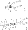
- Fig. 2 shows an exploded view of the entire rollator.
- the rollator basically has left and right frames, 1 and 2 respectively, each frame being supported on a front wheel 11, 12 and a rear wheel 9, 10.
- the two side frames 1 and 2 are connected both in the folded out and the collapsed state by a scissor frame 3.
- the scissor frame 3 comprises two cross pieces 31, 32, articulated to each other at a central pivot point 33.
- the lower end of each cross piece 31, 32 is hinged to the left or right frame 1 and 2 respectively at 35 and 34 respectively.
- an extension arm 36 and 37 respectively is hinged at 38 and 39 respectively.
- each extension arm 36, 37 is hinged to the left or right side frame 1 or 2 respectively, at 40 and 41 respectively.
- 13 designates a flexible toothed synchronous belt which will be described in more detail below.
- the scissor frame 3 can be collapsed bringing the side frames close together for storage, without any detachment of any hinge or pivot point, as shown in Fig. 1c .
- each cross piece 31, 32 there is welded a longitudinal slot piece 42 or 43 respectively.
- Each slot is designed to hold an end hem, containing a cord or a rod, of a fabric seat 44 stretched between the longitudinal slot pieces 42, 43.
- the rollator can be used either with or without the fabric seat 44.
- the fabric seat 44 collapses as the scissors frame 3 collapses.
- the scissors frame assembly is also locked against collapse by a small arm and spring mechanism 57 (see Fig. 1b ). This lock engages automatically when the rollator is fully expanded and is released for folding by pulling up on the arm, either directly or via a strap (not shown).
- each frame comprises a horizontal bar 51 and a vertical post 52.
- a handlebar assembly 5 is inserted into each post 52 and is adjusted to assume the correct height for the user.
- each handlebar assembly 5 comprises a brake lever 53 which is coupled via a cable to a brake 54 on the left or right rear wheel 9, 10 respectively.
- Fig. 3 shows clearly the journal bearing 55, supporting the axle 58 of the rear wheel 9 or 10.
- the forward end of the horizontal bar 51 of each side frame 1 and 2 has a journal bearing housing 21 for the steering post 8b of each front wheel fork 8.
- This front wheel fork 8 is shown most clearly in Figs. 4a and 4b which show the front wheel fork assembly in exploded and assembled views respectively.
- Figs. 4a and 4b do not show the journal bearing housing 21 welded to the front of the horizontal bar 51 of each side frame 1, 2.
- the assembled fork and side frame is only shown in Figs. 1a and 1b .
- the steering post 8b is provided with a flat side 22a fitting the flat side 22b on the interior of a toothed pulley 22.
- the steering fork can swivel/rotate as many degrees as desired in the journal bearing housing 21. It is held in place in the journal bearing housing 21 by a ring cap 26 secured in place by a washer 27 and screws 28 with intermediate ball bearings 24 and ball bearing races 23,25.
- a synchronous toothed belt 13 links the two toothed pulleys 22 and thus the forks 8 securely fixed to the pulleys 22, making sure that the two front wheels 11, 12 are always pointing in the same direction. This is important to see to prevent one of the front wheels from skewing off and assuming a position at right angles to the direction of motion of the walker.
- the housing 21 thus surrounds in very close proximity the entire portion of the synchronous belt in engagement with the toothed pulley 22. It is thus physically impossible for the belt 13 to slip in relation to the pulley 22, even when the belt is collapsed. Beyond holding the pulley always in secure engagement with the synchronous belt 13, the journal bearing housing also is a journal bearing for supporting the post 8b of the swivel fork 8.
- the housing 21 can be made to very precise tolerances in a single compact component. This surrounding of the synchronous belt also fulfills another requirement of shielding the pulley from rain and snow.
- FIGs. 7a and 7b other embodiments of the present invention involve replacing the synchronous toothed belt 13 and toothed pulley arrangement with a synchronous chain 14 and sprockets 29. Elements corresponding to those in the first embodiment above have received the same reference numerals. See also Fig. 8 which corresponds to the perspective view of Fig. 5 but using a synchronous chain 14 and sprockets 29 instead of a belt 13 and toothed pulleys 22.
- the sprockets 29 are each fixedly mounted on an individual steering post 8b, in the manner of the arrangement described above.
- the arrangement functions exactly as does the toothed belt/toothed pulley arrangement, with the precise tolerances of the inside of the journal bearing housing 21 preventing the chain 14 from ever becoming disengaged from or slipping in relation to the sprockets 29 (see Fig. 8 ).
- Figs. 9a and 9b show how this is achieved in one embodiment by having a loose ring or loop 61 around the toothed belt or chain.
- a tether cord 62 is attached at its ends to the longitudinal slot pieces 42, 43.
- the tether cord 62 passes in this particular embodiment from the one longitudinal slot piece 42 through an eye at strut hinge 35, through the loop 61, through a second eye at strut hinge 34 and finally up to longitudinal slot piece 43.
- the two longitudinal slot pieces 42, 43 will pull the tether cord ends upwards, thereby pulling the toothed belt 13 or the chain 14 rearwards so that it will be protected in the folded up position and will not stick out forwards.
- Figs. 10a, 10b , 10c and lod show an alternative embodiment from that shown in Figs. 9a and 9b .
- the loop 61 of Figs. 9a and 9b has been replaced with a rigid rectangular frame 61a holding an externally toothed wheel 63 freely rotatably mounted on an axle 64 held in the frame 61a.
- the toothed wheel 63 engages the toothed belt 13 and rotates when the front wheels 11, 12 are steered together.
- the interior of the frame 61a is dimensioned so as to prevent the toothed belt 13 from ever skipping or slipping over any of the teeth on the toothed wheel 63, thus always keeping the toothed wheel 63 and the frame 61a always exactly centrally placed midway in the belt 13, however the front wheels 12 and 13 are oriented.
- the tether cord 62 slips freely through a slot at the rear of the rectangular frame 61a. As is the case with the previously described tether arrangement, the ends of the tether cord are attached to the longitudinal slot pieces 42, 43 fixed to the diagonal struts 31, 32 (most clearly visible in Fig. 10d ).
- the brace frame 7 consists of two brace frame halves 70, 71 that are hinged together in the middle with two hinge brackets 72, 73.
- Arigid seat 74 is fixedly mounted to the one brace frame half 70.
- the brace frame 7 is locked against collapse by a small arm and spring mechanism 75 attached to said seat 74. This lock engages automatically with the brace frame half 71 when the rollator is fully expanded and is released for folding by pulling up on the arm, either directly or via a strap (not shown).
- the vertical brace frame 7 can fold rearwards as the rollator is folded up.
- brace frame arrangement shown in Figs. 7a and 7b can be combined with toothed pulleys and a synchronous belt as well, with or without a tether to pull the chain or belt rearwards as the rollator is folded up.
- the present invention is not limited to rollators, but encompasses other collapsible hand-propelled wheeled support devices, including push chairs and strollers utilizing swivelable front steering wheels.
Description
- Generally, embodiments of the invention relate to collapsible hand-propelled wheeled supports or carriers such as foldable rollators, walkers, pushchairs and strollers.
- More specifically, different embodiments of the application relate to foldable rollators, walkers, pushchairs and strollers which have two swiveling front caster wheels to steer the assembly when pushed in the desired direction.
- Many different types of rollators, walkers, pushchairs and strollers are known in the art. Many have front caster wheels which automatically align themselves in the direction towards which the assembly is pushed from behind. Many assemblies or carriers such as rollators, walkers, pushchairs and strollers are foldable for easy storage and transport in a car for example. Some designs also have means to make the front wheels always point in the same direction.
-
EP 1028 882 discloses a non-collapsible hand-propelled cart having two pairs of steerable wheels. Each pair of wheels has a tie rod between them to keep the two wheels of each pair pointing in the same direction. There is also a diagonal linkage connecting the two pairs and forcing each pair of wheels to be directed oppositely to the wheels of the other pair, thus facilitating turning using both the front and the rear wheels. -
EP 2 39 8687WO 2010/091513 ) shows a stroller with free independently swiveling front caster wheels. The stroller is collapsible by folding the top section forward over the bottom section, i.e. about an axis transverse to the longitudinal axis of the stroller. -
US 4 203 609 discloses a non-collapsible four-wheeled pull-cart, with a pair of front wheels linked to each other to turn in unison and a pair of rear wheels also linked to each other to turn in unision. The front and rear pairs are linked to each other to force the rear pair to turn counter to the front wheels thus making it easier for the cart to turn along an arc. -
US 3848884 describes a collapsible stroller which shows non-swivelable wheels (i.e. fixed in the straight-forward direction). Foldable linkages allow the entire stroller to be folded upwards sliding along a central shaft. -
WO2006122508 describes a collapsible stroller with two pairs of non-swivelable double wheels. Connecting lateral and longitudinal scissors mechanisms allow the stroller to be collapsed both laterally and longitudinally. -
FR 2843728 -
EP0890497 describes a collapsible pushchair having two directionally fixed rear wheels and two independently freely swivelable front wheels. Scissor mechanisms allow folding together of the pushchair both longitudinally and laterally. -
EP 2 366 372A1claim 1. It describes a laterally collapsible rollator having a scissors strut assembly between the two frames, but with no synchronous steering of the two front swivel wheels.WO2007101293 discloses a non-collapsible pushcart where the two pivotable wheels on right side are linked by a belt crossed midway so that these two right side wheels swivel counter to each other. The same arrangement is disposed for the left side wheels. This directs the rear wheels counter to the front wheels facilitating arcuate turning. -
NL1028058 -
DE 102004 036 864 A1 discloses a non-collapsable rollator where the two front steering wheels the swivel axles of which are coupled together via a friction belt, which can slip to allow the wheels to accommodate corners or to get back into alignment. -
GB 364269 A -
DE 19754984 A1 describes a non-collapsable hand lever for adjusting a vehicle seat where two toothed wheels at either end are coordinated by a toothed belt, which is restricted by guide means which prevent the toothed belt from skipping. - However, none of the related art discloses or hints at how to achieve the solutions provided by the present invention.
- The present invention intends to solve a complex of difficult-to-reconcile interrelated problems still present in the designs of the prior art:
- 1. It is desirable to allow the wheel assembly to be collapsible (foldable) laterally. This permits it to still stand on its wheels and be rolled forward even in the collapsed (folded) storage state, making it easier to handle it in the collapsed state, obviating heavy lifting. Lateral folding keeps the handles at the same level even when being folded together. This is important for a disabled person using a rollator for example.
- 2. It is desirable to have a hand-pushed wheeled assembly such as a rollator have its caster wheels always swivel in unison. This prevents one of the front wheels from being skewed to one side and halting abruptly the forward progress of the rollator. Synchronous steering also prevents so-called shimmying, which definitely detracts from feel, dependability and steerability. When being pushed at an angle over an obstacle such as a curb, synchronous steering will prevent the wheel first striking the curb at an angle from being forced parallel against the curb thus abruptly braking the entire rollator or stroller. With synchronous steering the friction of the other wheel not yet at the curb will prevent the forward wheel from changing its steering angle as it strikes the curb.
- 3. This swiveling in unison must always be secure without slippage, even after being folded up and folded out repeatedly.
- 4. It is desirable to allow unlimited swiveling of the front wheels (i.e. with no end stop). This allows for easier repeated backward and forward movement as desired.
- 5. It is desirable to eliminate unnecessary components, and to keep components requiring narrow tolerances to a minimum.
- 6. Any linkages should be securely protected from the elements.
- This entire complex of problems listed above finds its solution in the invention as defined in the appended main patent claim.
- Embodiments of the invention will now be described in more detail with reference to the appended drawings, wherein:
-
Figs. 1a and 1b show side and frontal views respectively of a four-wheeled laterally collapsible (foldable) rollator, which is one embodiment of the present invention. -
Fig. 1c shows the rollator ofFigs. 1a and 1b in its collapsed folded-up state. -
Fig. 2 shows an exploded view of the rollator shown inFigs. 1a and 1b . -
Fig. 3 is a view of the left-hand frame of the rollator. -
Figs. 4a and 4b show the assembled front wheel fork in exploded and unexploded views respectively. -
Fig. 5 shows in perspective the bearing housing with a toothed belt wheel and a synchronous belt. -
Fig. 6 shows a cross-sectional view through the bearing housing ofFig. 5 . -
Figs. 7a and 7b show a folded-out and a folded up view respectively of another embodiment of the present invention using a synchronous chain and a centrally hinged vertical brace frame as struts. -
Fig. 8 shows in perspective the bearing housing with a sprocket and a synchronous chain. -
Figs. 9a and 9b show a folded-out and a folded up view respectively of another embodiment of the present invention using a tether arrangement pull the belt/ chain rearwardly to a protected position during folding. -
Figs. 10a and 10b show a second embodiment of the tether arrangement according to the invention. -
Fig. 10c shows this second embodiment in a perspective view. -
Fig. 10d shows this second embodiment with the wheels and seat removed for better visibility of the tether arrangement. -
Figs. 1a and 1b show side and frontal views respectively of a rollator embodying the present invention.Fig. 2 shows an exploded view of the entire rollator. The rollator basically has left and right frames, 1 and 2 respectively, each frame being supported on afront wheel rear wheel side frames scissor frame 3. Thescissor frame 3 comprises twocross pieces central pivot point 33. The lower end of eachcross piece right frame cross piece extension arm extension arm right side frame scissor frame 3 can be collapsed bringing the side frames close together for storage, without any detachment of any hinge or pivot point, as shown inFig. 1c . - At the very upper end of each
cross piece longitudinal slot piece fabric seat 44 stretched between thelongitudinal slot pieces fabric seat 44. Thefabric seat 44 collapses as thescissors frame 3 collapses. - The scissors frame assembly is also locked against collapse by a small arm and spring mechanism 57 (see
Fig. 1b ). This lock engages automatically when the rollator is fully expanded and is released for folding by pulling up on the arm, either directly or via a strap (not shown). - As best can be seen in
Fig. 3 showing theleft side frame 2, each frame comprises ahorizontal bar 51 and avertical post 52. As can be seen inFigs. 1a, 1a and2 , ahandlebar assembly 5 is inserted into eachpost 52 and is adjusted to assume the correct height for the user. As can be seen in these figures eachhandlebar assembly 5 comprises abrake lever 53 which is coupled via a cable to abrake 54 on the left or rightrear wheel Fig. 3 shows clearly the journal bearing 55, supporting theaxle 58 of therear wheel - The forward end of the
horizontal bar 51 of eachside frame journal bearing housing 21 for thesteering post 8b of eachfront wheel fork 8. Thisfront wheel fork 8 is shown most clearly inFigs. 4a and 4b which show the front wheel fork assembly in exploded and assembled views respectively.Figs. 4a and 4b do not show thejournal bearing housing 21 welded to the front of thehorizontal bar 51 of eachside frame Figs. 1a and 1b . - The
steering post 8b is provided with aflat side 22a fitting theflat side 22b on the interior of atoothed pulley 22. The steering fork can swivel/rotate as many degrees as desired in thejournal bearing housing 21. It is held in place in thejournal bearing housing 21 by aring cap 26 secured in place by awasher 27 and screws 28 withintermediate ball bearings 24 and ball bearing races 23,25. - A synchronous
toothed belt 13 links the twotoothed pulleys 22 and thus theforks 8 securely fixed to thepulleys 22, making sure that the twofront wheels - It is known to steer a wheeled support by pushing it in the desired direction, with freely swivelable front wheels mounted in forks inclined slightly rearwardly. Hopefully, in prior art solutions within dependently freely swiveling front wheels, the two front swivel wheels will steer themselves in the same direction. The present invention insures that as the user steers the rollator by pushing it in the desired direction, both of the front steered wheels will swivel in exactly the same direction. The two front wheel/fork assemblies are otherwise freely unlimitedly swivelable, even multiple rotations and will never reach a rotational end position, where they would be prevented from steering properly, even if the user backs, turns and then proceeds forward. There is no need in the present invention to have any active steering of the front wheels as is the case in
NL1028058 - One significant problem which the present invention solves is combining lateral collapsibility with a synchronous belt which will never slip in its exact engagement with the toothed pulleys, when repeatedly folding up and folding out the rollator. If one of the pulleys were to slip a few cogs relative to the belt, this would render the rollator unusable, since the front wheels would then be compelled to steer in different directions. This problem is solved by the unique design of the front
journal bearing housings 21. As can be seen inFigs. 5 and6 , showing a perspective view and a cross sectional view respectively of only thejournal bearing housing 21, thetoothed pulley 22 and part of thesynchronous belt 13, there is an opening 60 (visible inFig. 3 as well) on the lower inside of thehousing 21. Thehousing 21 thus surrounds in very close proximity the entire portion of the synchronous belt in engagement with thetoothed pulley 22. It is thus physically impossible for thebelt 13 to slip in relation to thepulley 22, even when the belt is collapsed. Beyond holding the pulley always in secure engagement with thesynchronous belt 13, the journal bearing housing also is a journal bearing for supporting thepost 8b of theswivel fork 8. Thehousing 21 can be made to very precise tolerances in a single compact component. This surrounding of the synchronous belt also fulfills another requirement of shielding the pulley from rain and snow. - As can be seen in
Figs. 7a and 7b , other embodiments of the present invention involve replacing the synchronoustoothed belt 13 and toothed pulley arrangement with asynchronous chain 14 andsprockets 29. Elements corresponding to those in the first embodiment above have received the same reference numerals. See alsoFig. 8 which corresponds to the perspective view ofFig. 5 but using asynchronous chain 14 andsprockets 29 instead of abelt 13 and toothed pulleys 22. Thesprockets 29 are each fixedly mounted on anindividual steering post 8b, in the manner of the arrangement described above. Otherwise, the arrangement functions exactly as does the toothed belt/toothed pulley arrangement, with the precise tolerances of the inside of thejournal bearing housing 21 preventing thechain 14 from ever becoming disengaged from or slipping in relation to the sprockets 29 (seeFig. 8 ). - For embodiments employing either a synchronous toothed belt or a synchronous chain, it is possible to ensure that during the folding up the
toothed belt 13 orchain 14 always folds rearwardly between the two side frames, instead of forward where the toothed belt or chain would stick out and possibly become entangled and/or damaged.Figs. 9a and 9b show how this is achieved in one embodiment by having a loose ring orloop 61 around the toothed belt or chain. In this particular embodiment atether cord 62 is attached at its ends to thelongitudinal slot pieces tether cord 62 passes in this particular embodiment from the onelongitudinal slot piece 42 through an eye atstrut hinge 35, through theloop 61, through a second eye atstrut hinge 34 and finally up tolongitudinal slot piece 43. As the twoside frames longitudinal slot pieces toothed belt 13 or thechain 14 rearwards so that it will be protected in the folded up position and will not stick out forwards. -
Figs. 10a, 10b ,10c and lod (wheels and seat removed for visibility) show an alternative embodiment from that shown inFigs. 9a and 9b . Here theloop 61 ofFigs. 9a and 9b has been replaced with a rigidrectangular frame 61a holding an externallytoothed wheel 63 freely rotatably mounted on anaxle 64 held in theframe 61a. Thetoothed wheel 63 engages thetoothed belt 13 and rotates when thefront wheels frame 61a is dimensioned so as to prevent thetoothed belt 13 from ever skipping or slipping over any of the teeth on thetoothed wheel 63, thus always keeping thetoothed wheel 63 and theframe 61a always exactly centrally placed midway in thebelt 13, however thefront wheels tether cord 62 slips freely through a slot at the rear of therectangular frame 61a. As is the case with the previously described tether arrangement, the ends of the tether cord are attached to thelongitudinal slot pieces diagonal struts 31, 32 (most clearly visible inFig. 10d ). When the twoframes tether cord 62 are raised with thelongitudinal slot pieces rectangular frame 61a and thetoothed belt 13 will be pulled backwards in the same manner as described in the preceding paragraph with regard toFigs. 9a and 9b , finally assuming the position shown inFig. 10b . This embodiment has the advantage of stabilizing the toothed belt as it is pulled rearwardly, and the position of the rectangular frame/toothed wheel will always be midway along the toothed belt in all positions of the wheeled assembly. - As can be seen in
Figs. 7a and 7b it is possible to replace the scissors strut arrangement with avertical brace frame 7. Thebrace frame 7 consists of two brace frame halves 70, 71 that are hinged together in the middle with twohinge brackets Arigid seat 74 is fixedly mounted to the onebrace frame half 70. Thebrace frame 7 is locked against collapse by a small arm andspring mechanism 75 attached to saidseat 74. This lock engages automatically with thebrace frame half 71 when the rollator is fully expanded and is released for folding by pulling up on the arm, either directly or via a strap (not shown). Thevertical brace frame 7 can fold rearwards as the rollator is folded up. - The person skilled in the art will of course realize that the brace frame arrangement shown in
Figs. 7a and 7b can be combined with toothed pulleys and a synchronous belt as well, with or without a tether to pull the chain or belt rearwards as the rollator is folded up. - It is also understood that the present invention is not limited to rollators, but encompasses other collapsible hand-propelled wheeled support devices, including push chairs and strollers utilizing swivelable front steering wheels.
Claims (7)
- Collapsible hand-propelled wheeled support or carrier, such as a rollator, walker, pushchair or stroller, comprising:a) left and right side frames (1, 2) each supporting at least individual front and rear wheels (11, 9, 12, 10),b) each of said front wheels being mounted in its side frame on a vertical post (8b) and being swivelable in its side frame about a vertical axis,c) folding struts (31, 32, 36, 37; 70, 71, 72, 73) extending between said left and right side frames (1, 2), permitting moving said left and right frames laterally towards each other to a collapsed or folded storage position and away from each other to an expanded or folded-out stable position for use of the wheeled support or carrier,d) journal bearing housings (21) fixedly mounted on each of said left and right side frames and each swivelably holding one of said vertical posts (8b), characterized bye) the vertical post (8b) being a vertical steering post, a toothed pulley (22) or sprocket (29) fixedly mounted one on each vertical steering post (8b)f) a flexible toothed synchronous belt (13) or chain (14) engaging each toothed pulley or sprocket and extending between them,g) each of said journal bearing housings (21) surrounding said toothed synchronous belt (13) or synchronous chain (14) in such close proximity and circumferential extent as to prevent any disengagement or slippage between said synchronous belt (13) or synchronous chain (14) and the toothed pulleys (22) or sprockets (29).
- Wheeled support or carrier according to Claim 1, characterized in that said folding struts extending between said left and right side frames (1,2) comprise a centrally pivoted (33) scissors arrangement (31, 32, 36, 37).
- Wheeled support or carrier according to Claim 1, characterized in that said folding struts extending between said left and right side frames (1, 2) comprise a centrally hinged vertical brace frames (70, 71, 72, 73).
- Wheeled support or carrier according to Claim 1, characterized in that each of said front wheels is rollably mounted on its vertical steering post (8b) via a fork (8) fixed to said vertical steering post (8b).
- Wheeled support or carrier according to one of the preceding claims, characterized in that each of said front wheels is unlimitedly swivelable about a vertical axis.
- Wheeled support or carrier according to one of the preceding claims, characterized in that said synchronous belt (13) or chain (14) is tethered to a point or points on said folding struts, which moves or move upwards as the wheeled support or carrier is folded up, said tether comprising a loose loop or ring (61) through which the synchronous belt or chain freely runs and a tether cord (62) passing through or attached to said loop or ring (61), whereby the midpoint of said synchronous belt or chain is pulled rearward as the wheeled support or carrier is folded up.
- Wheeled support or carrier according to Claim 6, characterized in that said ring, through which the synchronous belt runs, is in the form of a rigid frame (61a) freely rotatably holding within it an externally toothed wheel (63) engaging on diametrically opposite sides said synchronous belt.
Applications Claiming Priority (2)
| Application Number | Priority Date | Filing Date | Title |
|---|---|---|---|
| EP14155246.3A EP2907496A1 (en) | 2014-02-14 | 2014-02-14 | Collapsible wheeled support or carrier |
| PCT/EP2015/052783 WO2015121264A1 (en) | 2014-02-14 | 2015-02-10 | Collapsible wheeled support or carrier |
Publications (2)
| Publication Number | Publication Date |
|---|---|
| EP3104820A1 EP3104820A1 (en) | 2016-12-21 |
| EP3104820B1 true EP3104820B1 (en) | 2019-10-30 |
Family
ID=50101791
Family Applications (2)
| Application Number | Title | Priority Date | Filing Date |
|---|---|---|---|
| EP14155246.3A Withdrawn EP2907496A1 (en) | 2014-02-14 | 2014-02-14 | Collapsible wheeled support or carrier |
| EP15703303.6A Active EP3104820B1 (en) | 2014-02-14 | 2015-02-10 | Collapsible wheeled support or carrier |
Family Applications Before (1)
| Application Number | Title | Priority Date | Filing Date |
|---|---|---|---|
| EP14155246.3A Withdrawn EP2907496A1 (en) | 2014-02-14 | 2014-02-14 | Collapsible wheeled support or carrier |
Country Status (6)
| Country | Link |
|---|---|
| US (1) | US9821827B2 (en) |
| EP (2) | EP2907496A1 (en) |
| JP (1) | JP6822731B2 (en) |
| CN (1) | CN106170277B (en) |
| ES (1) | ES2769809T3 (en) |
| WO (1) | WO2015121264A1 (en) |
Families Citing this family (23)
| Publication number | Priority date | Publication date | Assignee | Title |
|---|---|---|---|---|
| US8251079B1 (en) * | 2009-11-18 | 2012-08-28 | Katherine Lutz | Walker device for gait training |
| US9585807B2 (en) | 2015-05-16 | 2017-03-07 | Protostar, Inc., a Delaware Corporation | Collapsible upright wheeled walker apparatus |
| US10360394B2 (en) * | 2015-11-18 | 2019-07-23 | American Express Travel Related Services Company, Inc. | System and method for creating, tracking, and maintaining big data use cases |
| US9889872B2 (en) * | 2016-03-28 | 2018-02-13 | Ignio LLC | Multi-function mobility device |
| JP2018175666A (en) * | 2017-04-19 | 2018-11-15 | 株式会社幸和製作所 | Wheeled walker |
| JP2018175667A (en) * | 2017-04-19 | 2018-11-15 | 株式会社幸和製作所 | Wheeled walker |
| US10617592B2 (en) | 2017-10-06 | 2020-04-14 | Protostar, Inc., a Delaware Corporation | Wheeled walker |
| CN108785027A (en) * | 2018-06-29 | 2018-11-13 | 共享智能铸造产业创新中心有限公司 | Multifunction walking-aid device |
| CN109771233A (en) * | 2019-02-27 | 2019-05-21 | 共享智能铸造产业创新中心有限公司 | A kind of wheeled walker |
| US11071676B2 (en) * | 2019-04-05 | 2021-07-27 | Protostar, Inc. | Collapsible wheeled walker with stability enhancing bracket apparatus and method |
| USD902791S1 (en) | 2019-09-03 | 2020-11-24 | Protostar, Inc., a Delaware Corporation | Wheeled walker |
| TWI761728B (en) * | 2019-11-21 | 2022-04-21 | 緯創資通股份有限公司 | Walker and omnidirectional wheel thereof |
| WO2021119723A1 (en) * | 2019-12-19 | 2021-06-24 | Innoveso Pty Ltd | Folding rollator |
| USD953210S1 (en) * | 2020-06-17 | 2022-05-31 | Foshan Hct Medical Equipment Co., Ltd. | Foldable four-wheel walking aid |
| USD940601S1 (en) * | 2020-08-28 | 2022-01-11 | Qingfeng Li | Rollator |
| US11471363B1 (en) * | 2020-10-16 | 2022-10-18 | Tivadar A. Semesnyei | Position-adjustable accessory handle device for facilitated operation of a rollator |
| USD976763S1 (en) | 2021-02-10 | 2023-01-31 | Drive Devilbiss Healthcare | Rollator |
| US11559459B2 (en) | 2021-02-16 | 2023-01-24 | Drive Devilbiss Healthcare | Rollator |
| US20220395419A1 (en) * | 2021-06-10 | 2022-12-15 | Changde Yixiang Industrial Co., Ltd. | Assistive mobility device |
| CN113562043B (en) * | 2021-09-22 | 2021-12-31 | 山东明宇重工机械有限公司 | Steering driving device of electric pallet truck |
| US20230218469A1 (en) * | 2022-01-13 | 2023-07-13 | Valerie Gannaway | Curtain for a rolling walker |
| CN218220563U (en) * | 2022-05-24 | 2023-01-06 | 中山市春步医疗器械有限公司 | Connecting rod self-locking structure of double-folding walking aid |
| KR102632761B1 (en) * | 2022-12-07 | 2024-02-05 | 이진서 | Wheelbarrow |
Family Cites Families (30)
| Publication number | Priority date | Publication date | Assignee | Title |
|---|---|---|---|---|
| GB364269A (en) * | 1930-11-22 | 1932-01-07 | William Gibson Primrose | Improvements in means for steering trucks, chairs, beds, and other like manually-wheeled or wheelable articles |
| GB1321085A (en) * | 1970-04-17 | 1973-06-20 | Maclaren O F | Folding wheel chair |
| BE793645A (en) | 1972-01-03 | 1973-07-03 | Lines Walter M | WHEEL STROLLER |
| JPS53156400U (en) * | 1977-05-16 | 1978-12-08 | ||
| US4203609A (en) | 1978-07-31 | 1980-05-20 | Herman Miller, Inc. | Transport vehicle |
| US4660850A (en) * | 1984-10-12 | 1987-04-28 | Combi Co., Ltd. | Baby stroller |
| JPH0381103U (en) * | 1989-12-06 | 1991-08-20 | ||
| US5348336A (en) * | 1993-02-09 | 1994-09-20 | Fernie Geoffrey R | Walking aid |
| US5676388A (en) * | 1995-08-14 | 1997-10-14 | Bertani; Gilbert A. | Assisted walking apparatus |
| US6113128A (en) | 1997-07-11 | 2000-09-05 | Convaid Products, Inc. | Mobile seating arrangement |
| EP1028882B1 (en) | 1997-10-15 | 2006-03-01 | IGC (Australia) Pty. Ltd. | Steerable load-carrying assembly |
| DE19754984A1 (en) * | 1997-12-11 | 1999-06-17 | Contitech Antriebssysteme Gmbh | Adjustment mechanism for vehicle seats or office chairs |
| JP3080943B1 (en) * | 1999-04-22 | 2000-08-28 | 象印ベビー株式会社 | Old man car |
| US6814368B2 (en) | 2002-08-06 | 2004-11-09 | Pao-Hsien Cheng | Foldable stroller |
| JP4110001B2 (en) * | 2003-01-29 | 2008-07-02 | 株式会社島製作所 | Wheelbarrow |
| DE102004036864A1 (en) * | 2004-07-29 | 2006-02-16 | Josef Krampe | Trolley used as walking aid, has trolley frame used for friction-coupling and interconnecting wheel forks of front wheels with wheel forks of rear wheels |
| US7422550B1 (en) * | 2004-09-20 | 2008-09-09 | Michelle Pinero | Gait trainer |
| NL1028058C2 (en) | 2005-01-18 | 2006-07-19 | Univ Delft Tech | Rollator for helping disabled or elderly person walk, has steerable front wheels designed to be turned together |
| GB2426231A (en) | 2005-05-20 | 2006-11-22 | Kika Babies Entpr Co Ltd | Pushchair or stroller with scissor folding action |
| US7306246B2 (en) * | 2006-01-19 | 2007-12-11 | Gale Bradley D | Highly collapsible ambulatory assistive walker apparatus |
| CN2875405Y (en) * | 2006-01-26 | 2007-03-07 | 佛山市南海建泰铝制品有限公司 | Folding walking-aid cart |
| WO2007101293A1 (en) | 2006-03-06 | 2007-09-13 | Bradley Neil Smith | Steerable trolley or other vehicle |
| US7445217B1 (en) * | 2007-07-19 | 2008-11-04 | Donald J Price | Walk aid |
| US8333208B2 (en) * | 2008-04-10 | 2012-12-18 | Stander Inc. | Collapsible walking device |
| CA2752540C (en) | 2009-02-12 | 2017-06-13 | Clek Inc. | Foldable stroller |
| US8186367B1 (en) * | 2009-07-21 | 2012-05-29 | University Of South Florida | Foldable walker |
| NO331369B1 (en) | 2010-01-07 | 2011-12-12 | Handicare As | Welding device for cross-frame construction |
| US8827284B2 (en) * | 2010-08-20 | 2014-09-09 | Medline Industries, Inc. | Knee walker |
| US8726922B2 (en) * | 2012-06-18 | 2014-05-20 | Amie Pak | System and method for articulating walking aid |
| US8708363B1 (en) * | 2012-09-14 | 2014-04-29 | Joseph Hsiao-Wen Chang | Folding walker |
-
2014
- 2014-02-14 EP EP14155246.3A patent/EP2907496A1/en not_active Withdrawn
-
2015
- 2015-02-10 WO PCT/EP2015/052783 patent/WO2015121264A1/en active Application Filing
- 2015-02-10 JP JP2016549070A patent/JP6822731B2/en active Active
- 2015-02-10 US US15/117,801 patent/US9821827B2/en active Active
- 2015-02-10 ES ES15703303T patent/ES2769809T3/en active Active
- 2015-02-10 CN CN201580008523.3A patent/CN106170277B/en active Active
- 2015-02-10 EP EP15703303.6A patent/EP3104820B1/en active Active
Non-Patent Citations (1)
| Title |
|---|
| None * |
Also Published As
| Publication number | Publication date |
|---|---|
| JP6822731B2 (en) | 2021-01-27 |
| WO2015121264A1 (en) | 2015-08-20 |
| EP3104820A1 (en) | 2016-12-21 |
| CN106170277B (en) | 2019-08-20 |
| US9821827B2 (en) | 2017-11-21 |
| CN106170277A (en) | 2016-11-30 |
| EP2907496A1 (en) | 2015-08-19 |
| ES2769809T3 (en) | 2020-06-29 |
| JP2017511709A (en) | 2017-04-27 |
| US20170008544A1 (en) | 2017-01-12 |
Similar Documents
| Publication | Publication Date | Title |
|---|---|---|
| EP3104820B1 (en) | Collapsible wheeled support or carrier | |
| US10556610B2 (en) | Method for manufacturing maneuverable strollers | |
| US7677590B2 (en) | Stroller having extendable handle | |
| US20060255564A1 (en) | Steerable wheeled cart | |
| AU2018204399B2 (en) | Child Transporter | |
| US8146926B2 (en) | Steerable and convertible running stroller | |
| NZ521312A (en) | Steerable load-carrying assemblies | |
| US20090152826A1 (en) | Cargo cart with hitch for wheeled mobility device | |
| GB2518977A (en) | A jogging stroller frame with an automatic wheel flattening and folding mechanism | |
| EP1488981A1 (en) | Wheeled foldable frame, particularly for pushchairs, prams, wheelchairs and the like | |
| US20220194458A1 (en) | Transportation apparatus | |
| EP2895374B1 (en) | Shopping trolley with platform for a child | |
| RU2788593C2 (en) | Stroller attachment device and double baby stroller assembly | |
| ES2635619B1 (en) | HORSE FOR CHILD CAR, CHILD CAR AND USE OF A CORRESPONDING HORSE | |
| JP6497603B2 (en) | Silver car | |
| AU746765B2 (en) | Steerable load-carrying assemblies | |
| CN104802843A (en) | Baby stroller | |
| CA2457374A1 (en) | Child's pushchair with folding frame, integrating means to help folding |
Legal Events
| Date | Code | Title | Description |
|---|---|---|---|
| PUAI | Public reference made under article 153(3) epc to a published international application that has entered the european phase |
Free format text: ORIGINAL CODE: 0009012 |
|
| STAA | Information on the status of an ep patent application or granted ep patent |
Free format text: STATUS: REQUEST FOR EXAMINATION WAS MADE |
|
| 17P | Request for examination filed |
Effective date: 20160715 |
|
| AK | Designated contracting states |
Kind code of ref document: A1 Designated state(s): AL AT BE BG CH CY CZ DE DK EE ES FI FR GB GR HR HU IE IS IT LI LT LU LV MC MK MT NL NO PL PT RO RS SE SI SK SM TR |
|
| AX | Request for extension of the european patent |
Extension state: BA ME |
|
| DAX | Request for extension of the european patent (deleted) | ||
| RAP1 | Party data changed (applicant data changed or rights of an application transferred) |
Owner name: TRIONIC SVERIGE AB |
|
| RIN1 | Information on inventor provided before grant (corrected) |
Inventor name: KINDBERG, STEFAN |
|
| GRAP | Despatch of communication of intention to grant a patent |
Free format text: ORIGINAL CODE: EPIDOSNIGR1 |
|
| STAA | Information on the status of an ep patent application or granted ep patent |
Free format text: STATUS: GRANT OF PATENT IS INTENDED |
|
| RIC1 | Information provided on ipc code assigned before grant |
Ipc: B62B 7/04 20060101ALI20190508BHEP Ipc: B62B 3/02 20060101ALI20190508BHEP Ipc: A61H 3/04 20060101AFI20190508BHEP Ipc: B62B 7/06 20060101ALI20190508BHEP |
|
| INTG | Intention to grant announced |
Effective date: 20190611 |
|
| GRAS | Grant fee paid |
Free format text: ORIGINAL CODE: EPIDOSNIGR3 |
|
| GRAA | (expected) grant |
Free format text: ORIGINAL CODE: 0009210 |
|
| STAA | Information on the status of an ep patent application or granted ep patent |
Free format text: STATUS: THE PATENT HAS BEEN GRANTED |
|
| AK | Designated contracting states |
Kind code of ref document: B1 Designated state(s): AL AT BE BG CH CY CZ DE DK EE ES FI FR GB GR HR HU IE IS IT LI LT LU LV MC MK MT NL NO PL PT RO RS SE SI SK SM TR |
|
| REG | Reference to a national code |
Ref country code: GB Ref legal event code: FG4D |
|
| REG | Reference to a national code |
Ref country code: CH Ref legal event code: EP |
|
| REG | Reference to a national code |
Ref country code: AT Ref legal event code: REF Ref document number: 1195381 Country of ref document: AT Kind code of ref document: T Effective date: 20191115 |
|
| REG | Reference to a national code |
Ref country code: DE Ref legal event code: R096 Ref document number: 602015040651 Country of ref document: DE |
|
| REG | Reference to a national code |
Ref country code: IE Ref legal event code: FG4D |
|
| REG | Reference to a national code |
Ref country code: CH Ref legal event code: NV Representative=s name: DENNEMEYER AG, CH |
|
| REG | Reference to a national code |
Ref country code: SE Ref legal event code: TRGR |
|
| REG | Reference to a national code |
Ref country code: NL Ref legal event code: FP |
|
| REG | Reference to a national code |
Ref country code: LT Ref legal event code: MG4D |
|
| PG25 | Lapsed in a contracting state [announced via postgrant information from national office to epo] |
Ref country code: PL Free format text: LAPSE BECAUSE OF FAILURE TO SUBMIT A TRANSLATION OF THE DESCRIPTION OR TO PAY THE FEE WITHIN THE PRESCRIBED TIME-LIMIT Effective date: 20191030 Ref country code: LT Free format text: LAPSE BECAUSE OF FAILURE TO SUBMIT A TRANSLATION OF THE DESCRIPTION OR TO PAY THE FEE WITHIN THE PRESCRIBED TIME-LIMIT Effective date: 20191030 Ref country code: GR Free format text: LAPSE BECAUSE OF FAILURE TO SUBMIT A TRANSLATION OF THE DESCRIPTION OR TO PAY THE FEE WITHIN THE PRESCRIBED TIME-LIMIT Effective date: 20200131 Ref country code: PT Free format text: LAPSE BECAUSE OF FAILURE TO SUBMIT A TRANSLATION OF THE DESCRIPTION OR TO PAY THE FEE WITHIN THE PRESCRIBED TIME-LIMIT Effective date: 20200302 Ref country code: FI Free format text: LAPSE BECAUSE OF FAILURE TO SUBMIT A TRANSLATION OF THE DESCRIPTION OR TO PAY THE FEE WITHIN THE PRESCRIBED TIME-LIMIT Effective date: 20191030 Ref country code: BG Free format text: LAPSE BECAUSE OF FAILURE TO SUBMIT A TRANSLATION OF THE DESCRIPTION OR TO PAY THE FEE WITHIN THE PRESCRIBED TIME-LIMIT Effective date: 20200130 Ref country code: NO Free format text: LAPSE BECAUSE OF FAILURE TO SUBMIT A TRANSLATION OF THE DESCRIPTION OR TO PAY THE FEE WITHIN THE PRESCRIBED TIME-LIMIT Effective date: 20200130 Ref country code: LV Free format text: LAPSE BECAUSE OF FAILURE TO SUBMIT A TRANSLATION OF THE DESCRIPTION OR TO PAY THE FEE WITHIN THE PRESCRIBED TIME-LIMIT Effective date: 20191030 |
|
| PG25 | Lapsed in a contracting state [announced via postgrant information from national office to epo] |
Ref country code: IS Free format text: LAPSE BECAUSE OF FAILURE TO SUBMIT A TRANSLATION OF THE DESCRIPTION OR TO PAY THE FEE WITHIN THE PRESCRIBED TIME-LIMIT Effective date: 20200229 Ref country code: HR Free format text: LAPSE BECAUSE OF FAILURE TO SUBMIT A TRANSLATION OF THE DESCRIPTION OR TO PAY THE FEE WITHIN THE PRESCRIBED TIME-LIMIT Effective date: 20191030 Ref country code: RS Free format text: LAPSE BECAUSE OF FAILURE TO SUBMIT A TRANSLATION OF THE DESCRIPTION OR TO PAY THE FEE WITHIN THE PRESCRIBED TIME-LIMIT Effective date: 20191030 |
|
| REG | Reference to a national code |
Ref country code: ES Ref legal event code: FG2A Ref document number: 2769809 Country of ref document: ES Kind code of ref document: T3 Effective date: 20200629 |
|
| PG25 | Lapsed in a contracting state [announced via postgrant information from national office to epo] |
Ref country code: AL Free format text: LAPSE BECAUSE OF FAILURE TO SUBMIT A TRANSLATION OF THE DESCRIPTION OR TO PAY THE FEE WITHIN THE PRESCRIBED TIME-LIMIT Effective date: 20191030 |
|
| PG25 | Lapsed in a contracting state [announced via postgrant information from national office to epo] |
Ref country code: CZ Free format text: LAPSE BECAUSE OF FAILURE TO SUBMIT A TRANSLATION OF THE DESCRIPTION OR TO PAY THE FEE WITHIN THE PRESCRIBED TIME-LIMIT Effective date: 20191030 Ref country code: RO Free format text: LAPSE BECAUSE OF FAILURE TO SUBMIT A TRANSLATION OF THE DESCRIPTION OR TO PAY THE FEE WITHIN THE PRESCRIBED TIME-LIMIT Effective date: 20191030 Ref country code: DK Free format text: LAPSE BECAUSE OF FAILURE TO SUBMIT A TRANSLATION OF THE DESCRIPTION OR TO PAY THE FEE WITHIN THE PRESCRIBED TIME-LIMIT Effective date: 20191030 Ref country code: EE Free format text: LAPSE BECAUSE OF FAILURE TO SUBMIT A TRANSLATION OF THE DESCRIPTION OR TO PAY THE FEE WITHIN THE PRESCRIBED TIME-LIMIT Effective date: 20191030 |
|
| REG | Reference to a national code |
Ref country code: DE Ref legal event code: R097 Ref document number: 602015040651 Country of ref document: DE |
|
| REG | Reference to a national code |
Ref country code: AT Ref legal event code: MK05 Ref document number: 1195381 Country of ref document: AT Kind code of ref document: T Effective date: 20191030 |
|
| PG25 | Lapsed in a contracting state [announced via postgrant information from national office to epo] |
Ref country code: SK Free format text: LAPSE BECAUSE OF FAILURE TO SUBMIT A TRANSLATION OF THE DESCRIPTION OR TO PAY THE FEE WITHIN THE PRESCRIBED TIME-LIMIT Effective date: 20191030 Ref country code: SM Free format text: LAPSE BECAUSE OF FAILURE TO SUBMIT A TRANSLATION OF THE DESCRIPTION OR TO PAY THE FEE WITHIN THE PRESCRIBED TIME-LIMIT Effective date: 20191030 |
|
| PLBE | No opposition filed within time limit |
Free format text: ORIGINAL CODE: 0009261 |
|
| STAA | Information on the status of an ep patent application or granted ep patent |
Free format text: STATUS: NO OPPOSITION FILED WITHIN TIME LIMIT |
|
| 26N | No opposition filed |
Effective date: 20200731 |
|
| REG | Reference to a national code |
Ref country code: BE Ref legal event code: MM Effective date: 20200229 |
|
| PG25 | Lapsed in a contracting state [announced via postgrant information from national office to epo] |
Ref country code: LU Free format text: LAPSE BECAUSE OF NON-PAYMENT OF DUE FEES Effective date: 20200210 Ref country code: MC Free format text: LAPSE BECAUSE OF FAILURE TO SUBMIT A TRANSLATION OF THE DESCRIPTION OR TO PAY THE FEE WITHIN THE PRESCRIBED TIME-LIMIT Effective date: 20191030 |
|
| PG25 | Lapsed in a contracting state [announced via postgrant information from national office to epo] |
Ref country code: AT Free format text: LAPSE BECAUSE OF FAILURE TO SUBMIT A TRANSLATION OF THE DESCRIPTION OR TO PAY THE FEE WITHIN THE PRESCRIBED TIME-LIMIT Effective date: 20191030 Ref country code: SI Free format text: LAPSE BECAUSE OF FAILURE TO SUBMIT A TRANSLATION OF THE DESCRIPTION OR TO PAY THE FEE WITHIN THE PRESCRIBED TIME-LIMIT Effective date: 20191030 |
|
| PG25 | Lapsed in a contracting state [announced via postgrant information from national office to epo] |
Ref country code: IE Free format text: LAPSE BECAUSE OF NON-PAYMENT OF DUE FEES Effective date: 20200210 |
|
| PG25 | Lapsed in a contracting state [announced via postgrant information from national office to epo] |
Ref country code: BE Free format text: LAPSE BECAUSE OF NON-PAYMENT OF DUE FEES Effective date: 20200229 |
|
| PG25 | Lapsed in a contracting state [announced via postgrant information from national office to epo] |
Ref country code: TR Free format text: LAPSE BECAUSE OF FAILURE TO SUBMIT A TRANSLATION OF THE DESCRIPTION OR TO PAY THE FEE WITHIN THE PRESCRIBED TIME-LIMIT Effective date: 20191030 Ref country code: MT Free format text: LAPSE BECAUSE OF FAILURE TO SUBMIT A TRANSLATION OF THE DESCRIPTION OR TO PAY THE FEE WITHIN THE PRESCRIBED TIME-LIMIT Effective date: 20191030 Ref country code: CY Free format text: LAPSE BECAUSE OF FAILURE TO SUBMIT A TRANSLATION OF THE DESCRIPTION OR TO PAY THE FEE WITHIN THE PRESCRIBED TIME-LIMIT Effective date: 20191030 |
|
| PG25 | Lapsed in a contracting state [announced via postgrant information from national office to epo] |
Ref country code: MK Free format text: LAPSE BECAUSE OF FAILURE TO SUBMIT A TRANSLATION OF THE DESCRIPTION OR TO PAY THE FEE WITHIN THE PRESCRIBED TIME-LIMIT Effective date: 20191030 |
|
| PGFP | Annual fee paid to national office [announced via postgrant information from national office to epo] |
Ref country code: NL Payment date: 20230216 Year of fee payment: 9 |
|
| PGFP | Annual fee paid to national office [announced via postgrant information from national office to epo] |
Ref country code: FR Payment date: 20230221 Year of fee payment: 9 Ref country code: CH Payment date: 20230307 Year of fee payment: 9 |
|
| PGFP | Annual fee paid to national office [announced via postgrant information from national office to epo] |
Ref country code: SE Payment date: 20230216 Year of fee payment: 9 Ref country code: IT Payment date: 20230223 Year of fee payment: 9 Ref country code: GB Payment date: 20230221 Year of fee payment: 9 Ref country code: DE Payment date: 20230216 Year of fee payment: 9 |
|
| PGFP | Annual fee paid to national office [announced via postgrant information from national office to epo] |
Ref country code: ES Payment date: 20230427 Year of fee payment: 9 |
|
| PGFP | Annual fee paid to national office [announced via postgrant information from national office to epo] |
Ref country code: NL Payment date: 20240219 Year of fee payment: 10 Ref country code: ES Payment date: 20240326 Year of fee payment: 10 |