EP3104539A1 - Messsystem und messverfahren zur messung von prüflingen mit antennen-arrays - Google Patents
Messsystem und messverfahren zur messung von prüflingen mit antennen-arrays Download PDFInfo
- Publication number
- EP3104539A1 EP3104539A1 EP15170968.0A EP15170968A EP3104539A1 EP 3104539 A1 EP3104539 A1 EP 3104539A1 EP 15170968 A EP15170968 A EP 15170968A EP 3104539 A1 EP3104539 A1 EP 3104539A1
- Authority
- EP
- European Patent Office
- Prior art keywords
- antenna
- measuring
- under test
- device under
- array
- Prior art date
- Legal status (The legal status is an assumption and is not a legal conclusion. Google has not performed a legal analysis and makes no representation as to the accuracy of the status listed.)
- Granted
Links
Images


Classifications
-
- H—ELECTRICITY
- H04—ELECTRIC COMMUNICATION TECHNIQUE
- H04B—TRANSMISSION
- H04B17/00—Monitoring; Testing
- H04B17/10—Monitoring; Testing of transmitters
- H04B17/11—Monitoring; Testing of transmitters for calibration
- H04B17/12—Monitoring; Testing of transmitters for calibration of transmit antennas, e.g. of the amplitude or phase
-
- H—ELECTRICITY
- H04—ELECTRIC COMMUNICATION TECHNIQUE
- H04B—TRANSMISSION
- H04B17/00—Monitoring; Testing
- H04B17/20—Monitoring; Testing of receivers
- H04B17/21—Monitoring; Testing of receivers for calibration; for correcting measurements
-
- H—ELECTRICITY
- H04—ELECTRIC COMMUNICATION TECHNIQUE
- H04B—TRANSMISSION
- H04B7/00—Radio transmission systems, i.e. using radiation field
- H04B7/02—Diversity systems; Multi-antenna system, i.e. transmission or reception using multiple antennas
- H04B7/04—Diversity systems; Multi-antenna system, i.e. transmission or reception using multiple antennas using two or more spaced independent antennas
- H04B7/06—Diversity systems; Multi-antenna system, i.e. transmission or reception using multiple antennas using two or more spaced independent antennas at the transmitting station
- H04B7/0613—Diversity systems; Multi-antenna system, i.e. transmission or reception using multiple antennas using two or more spaced independent antennas at the transmitting station using simultaneous transmission
- H04B7/0615—Diversity systems; Multi-antenna system, i.e. transmission or reception using multiple antennas using two or more spaced independent antennas at the transmitting station using simultaneous transmission of weighted versions of same signal
- H04B7/0617—Diversity systems; Multi-antenna system, i.e. transmission or reception using multiple antennas using two or more spaced independent antennas at the transmitting station using simultaneous transmission of weighted versions of same signal for beam forming
-
- H—ELECTRICITY
- H04—ELECTRIC COMMUNICATION TECHNIQUE
- H04W—WIRELESS COMMUNICATION NETWORKS
- H04W24/00—Supervisory, monitoring or testing arrangements
- H04W24/06—Testing, supervising or monitoring using simulated traffic
-
- H—ELECTRICITY
- H04—ELECTRIC COMMUNICATION TECHNIQUE
- H04B—TRANSMISSION
- H04B17/00—Monitoring; Testing
- H04B17/10—Monitoring; Testing of transmitters
- H04B17/101—Monitoring; Testing of transmitters for measurement of specific parameters of the transmitter or components thereof
- H04B17/102—Power radiated at antenna
-
- H—ELECTRICITY
- H04—ELECTRIC COMMUNICATION TECHNIQUE
- H04W—WIRELESS COMMUNICATION NETWORKS
- H04W84/00—Network topologies
- H04W84/02—Hierarchically pre-organised networks, e.g. paging networks, cellular networks, WLAN [Wireless Local Area Network] or WLL [Wireless Local Loop]
- H04W84/04—Large scale networks; Deep hierarchical networks
- H04W84/042—Public Land Mobile systems, e.g. cellular systems
Definitions
- the invention relates to a system and method for measuring for communication devices comprising antenna-arrays, especially antenna-arrays used for beamforming.
- the next mobile communications technology 5G is imminent.
- 5G a move to even higher frequencies and larger bandwidths are to be expected.
- frequencies up to 75 GHz are in discussion.
- the antenna technology is a core aspect. High antenna gains are necessary. In order to reach such high antenna gains, the use of antennas with a large number of radiating elements, especially antenna-arrays are in discussion.
- the active antenna will be an integral part of the device under test. Parameters as output power, neighbor channel influence, and modulation accuracy can only be accurately measured taking the antenna into account. Especially, the antenna diagram resulting in the maximum gain direction of the respective antenna-array has to be taken into account.
- the document US 2013/0093447 A1 shows a measuring system for performing over-the-air measurements on devices under test.
- the respective device under test is placed within a device under test holder, which is rotatable by a device under test a rotator. Using a single fixed measuring antenna, measurements are performed.
- the measuring system according to US 2013/0093447 A1 though does not take devices under test using antenna-arrays, beamforming, antenna diagrams and maximum gain directions of an antenna-array into account. It is therefore not possible to perform accurate measurements on future generations of devices under test using the measuring system.
- the object of the present invention is to provide a measuring system and measuring method for performing accurate measurements on communication devices comprising antenna-arrays.
- a measuring system for measuring a communication device under test comprises a control unit, a measuring device, at least one measuring antenna and a device under test mount.
- the at least one measuring antenna is advantageously mounted in a fixed location and orientation regarding the device under test mount.
- the device under test mount is adapted to hold the device under test and rotate the device under test around at least one axis.
- the measuring system is furthermore adapted for measuring a communication device under test comprising an antenna-array.
- a control unit is adapted to set an antenna characteristic of the antenna-array of the device under test, whereby adjusting a set maximum gain direction of the antenna-array.
- control unit is adapted to instruct the device under test mount to rotate the communication device under test compensating for the set maximum gain direction of the antenna-array, so that the set maximum gain direction of the antenna-array meets a direction of the measuring antenna regarding the device under test.
- control unit is adapted to determine an actual maximum gain direction of the antenna-array by iteratively instructing the device under test mount to rotate the device under test to determine a present gain of the antenna-array, and to determining the actual maximum gain direction as a rotation direction of the device under test mount of maximal gain. It is thus possible to accurately determine the function of setting the antenna characteristics and the maximum gain direction of the antenna-array with a low hardware effort.
- control unit is adapted to determine a maximum gain misalignment as a measuring result by determining a difference between the set maximum gain direction of the antenna-array and the actual maximum gain direction of the antenna-array.
- a very simple parameter is generated for determining the quality of an antenna-array adjustment.
- control unit is adapted to determine the actual maximum gain direction of the antenna-array by respectively after instructing the device under test mount to rotate the device under test and determining a present gain of the antenna-array, determining a gain-difference of the present gain regarding a directly previous gain, reversing a direction of rotating the device under test for a following iteration, if the gain difference is negative and above a first pre-specified threshold, reducing a rotation amount for a following iteration, if the gain difference is positive and below a second pre-specified threshold and/or determining the actual maximum gain direction of the antenna-array as a present direction, if the gain difference is below the first pre-specified threshold.
- the measuring system comprises a signal generator adapted to generate a measuring signal.
- the measuring antenna is then adapted to transmit the measuring signal generated by the signal generator to the device under test. It is thus possible to perform reception measurements with the measuring system with minimal effort.
- control unit is adapted to determine the present gain of the antenna-array by respectively instructing the device under test to measure a reception power of the measuring signal and comparing the reception power to a transmission power of the measuring signal.
- a very efficient determining of the present gain of the antenna-array is thereby possible.
- the measuring system comprises a signal analyzer.
- the control unit is then adapted to instruct the communication device under test to generate a measuring signal and transmitted to the measuring antenna.
- the signal analyzer is adapted to receive the measuring signal. It is thereby possible to very efficiently to perform a transmission measurement.
- control unit is adapted to determine the present gain of the antenna-array by respectively instructing the signal analyzer to measure a reception power of the measuring signal and by comparing the reception power to a transmission power of the measuring signal.
- a very efficient determining of the present gain of the antenna-array is thereby possible.
- the device under test mount is adapted to rotate the device under test around to axes. Thereby, a three-dimensional measuring is possible.
- a measuring method for performing measurements on a communication device under test having an antenna-array is provided.
- the measuring method advantageously comprises positioning at least one measuring antenna in a fixed location and orientation regarding a device under test mount and positioning the communication device under test in the device under test mount.
- the measuring method further comprises setting an antenna characteristic of the antenna-array of the communication device under test thereby adjusting a set maximum gain direction of the antenna-array.
- the method comprises the step of rotating the communication device under test using the device under test mount and compensating for the set maximum gain direction of the antenna-array, so that the set maximum gain direction of the antenna-array meets a direction of the measuring antenna regarding the device under test.
- the method preferably comprises determining an actual maximum gain direction of the antenna-array by iteratively rotating the communication device under test using the device under test mount, determining a present gain of the antenna-array and determining the actual maximum gain direction as a rotation direction of the device under test mount of maximal gain.
- the measuring system 10 comprises a measuring device 1, a measuring antenna 3 connected to the measuring device 1 by a coaxial cable 2 and a device under test mount 4.
- the device under test mount 4 holds a communication device under test 5.
- the device under test 5 comprises an antenna-array, which is though not depicted in detail here. By adjusting the antenna characteristic of the antenna-array, different antenna characteristics and thereby maximum gain directions 6 of the antenna-array can be set.
- the device under test 5 When performing a transmission measurement, the device under test 5 transmits a measuring signal using a presently set antenna characteristic and thereby a presently set maximum gain direction 6.
- the measuring signal is received by the measuring antenna 3 and handed on to the measuring device 1 via the coaxial cable 2.
- the measuring device 1 is for example a signal analyzer.
- the measuring device For performing a reception measurement, the measuring device 1, in this case for example a signal generator, generates a measuring signal and hands it to the measuring antenna 3 via the coaxial cable 2.
- the measuring antenna 3 transmits the measuring signal to the device under test 5, which receives it.
- the antenna characteristic of the antenna-array of the device under test 5 also influences the reception of the measuring signal from the measuring antenna 3.
- the device under test mount 4 and the measuring antenna 3 are located in fixed positions with regard to each other. This allows for a very simple hardware setup.
- the device under test mount 4 though is rotatable around at least one axis, preferably around two axes. It is thereby possible to rotate the device under test 5 so that the maximum gain direction 6 of the antenna-array points towards the measuring antenna 3 at all times. Details of this function are explained lateron, especially with regard to Fig. 4a - 4d .
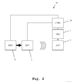
- a second embodiment of the inventive measuring system 10 is depicted.
- a block-diagram is shown.
- the control unit 20 is adapted to control the function of the device under test 5 and the device under test mount 4.
- control unit 20 controls the function of the measuring device 1. Since here, a transmission measurement is performed, the device under test 5 is instructed by the control unit 20 to emit a measuring signal, which is then received by the measuring antenna 3 and further processed by the measuring device 1, which in this case for example is a signal analyzer. Moreover, the control unit 20 controls the device under test mount 4 to rotate the device under test 5 as required.
- a third embodiment of the inventive measuring system 10 is shown.
- the measuring system 10 is configured for performing a reception measurement by the device under test 5.
- the control unit 20 controls the measuring device 1, which in this case can for example be a signal generator, to generate a measuring signal and transmit it to the device under test 5 using the measuring antenna 3.
- the control unit 20 controls the device under test 5 to receive the measuring signal.
- the control unit 20 controls the device under test mount 4, as required.
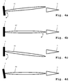
- FIG. 4a an initial situation after placing a device under test 5 on the device under test mount 4 is shown.
- the device under test 5 is set to a certain antenna characteristic resulting in a maximum gain direction 61 of the antenna-array.
- the set maximum gain direction 61 of the antenna-array is not in alignment with the direction of the measuring antenna 3.
- the device under test mount 4 is rotated around at least one axis in order to align the set maximum gain direction 61 with the direction of the measuring antenna 3. In case of a transmission measurement, this is done by iteratively rotating the device under test mount and measuring the reception power received by the measuring antenna 3. When a maximum reception power is reached, an alignment of the set maximum gain direction 61 with the direction of the measuring antenna 3 is achieved. This is depicted in Fig. 4b .
- a further antenna characteristic of the antenna-array is set.
- the set maximum gain direction 62 of the antenna-array is changed to the maximum gain direction 63 as depicted in Fig. 4c .
- the device under test mount is now rotated by the exact same amount into the opposite direction resulting in a rotation of the maximum gain direction 64 as depicted in Fig. 4d .
- the maximum gain direction 64 is now perfectly in alignment with the measuring antenna 3. In practice, this is though not necessarily the case.
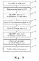
- a transmission measurement is described.
- a device under test is placed on a device under test mount.
- a measuring signal is emitted by the device under test.
- the device under test mount angle is adjusted by rotating the device under test mount for a maximal reception power by the measuring antenna.
- an antenna characteristic of the antenna-array of the device under test is adjusted by an angle ⁇ , especially a beamforming angle is adjusted.
- the device under test mount is rotated by the angle ⁇ into the opposite direction.
- a sixth step 55 again the device under test mount is rotated to achieve maximum reception power.
- a seventh step 56 as a measuring result, a maximum gain direction misalignment is determined as a measuring result by subtracting the set maximum gain direction and the present maximum gain direction determined in the sixth step 55.
- additional measurements can be performed on the device under test at this position of maximum gain direction of the measuring antenna. Thereby, reproducible measuring conditions can be achieved every time a device under test is measured.
- a reception measurement is described.
- a device under test is placed on a device under test mount.
- a measuring signal is emitted by a measuring device and received by the device under test.
- the device under test mount is rotated to adjust a device under test mount angle for maximal reception power. This reception power is detected by the device under test itself.
- the antenna characteristic of the device under test is adjusted resulting in a rotation of a set maximum gain direction of the antenna-array by an angle of ⁇ .
- the device under test mount is rotated in the opposite direction by the angle ⁇ .
- a measuring result is determined by determining a maximum gain direction misalignment by calculating the difference between the set maximum gain direction and the present maximum gain direction. Also here, in an optional eighth step 67, further measurements can now be performed on the device under test.
- the invention is not limited to the examples shown above. Especially it is not limited to mobile telephones or base stations. Any communication device, which comprises a plurality of antennas grouped in an antenna-array can be used as a device under test. Also the measuring device described above is not limited to the examples of signal generator and signal analyzer. Also other measuring devices can be used. The characteristics of the exemplary embodiments can be used in any advantageous combination.
Priority Applications (2)
| Application Number | Priority Date | Filing Date | Title |
|---|---|---|---|
| EP15170968.0A EP3104539B1 (de) | 2015-06-08 | 2015-06-08 | Messsystem und messverfahren zur messung von prüflingen mit antennen-arrays |
| US15/171,928 US9780890B2 (en) | 2015-06-08 | 2016-06-02 | Wireless measuring system and method for measurement of a device under test with an antenna-array, considering maximum gain direction of the antenna array |
Applications Claiming Priority (1)
| Application Number | Priority Date | Filing Date | Title |
|---|---|---|---|
| EP15170968.0A EP3104539B1 (de) | 2015-06-08 | 2015-06-08 | Messsystem und messverfahren zur messung von prüflingen mit antennen-arrays |
Publications (2)
| Publication Number | Publication Date |
|---|---|
| EP3104539A1 true EP3104539A1 (de) | 2016-12-14 |
| EP3104539B1 EP3104539B1 (de) | 2017-09-13 |
Family
ID=53298252
Family Applications (1)
| Application Number | Title | Priority Date | Filing Date |
|---|---|---|---|
| EP15170968.0A Active EP3104539B1 (de) | 2015-06-08 | 2015-06-08 | Messsystem und messverfahren zur messung von prüflingen mit antennen-arrays |
Country Status (2)
| Country | Link |
|---|---|
| US (1) | US9780890B2 (de) |
| EP (1) | EP3104539B1 (de) |
Cited By (8)
| Publication number | Priority date | Publication date | Assignee | Title |
|---|---|---|---|---|
| WO2018128950A3 (en) * | 2017-01-06 | 2018-09-27 | Intel IP Corporation | Ue testing system for rf characteristics for the new radio standard |
| WO2018219680A1 (en) * | 2017-05-31 | 2018-12-06 | Fraunhofer-Gesellschaft zur Förderung der angewandten Forschung e.V. | Apparatus, measurement system for testing an apparatus and methods for operating the same |
| EP3416311A1 (de) * | 2017-06-14 | 2018-12-19 | Rohde & Schwarz GmbH & Co. KG | Testsystem und testverfahren |
| EP3432490A1 (de) * | 2017-07-21 | 2019-01-23 | Rohde & Schwarz GmbH & Co. KG | Messsystem mit positionierungssystem für strahlformungsmessungen und messverfahren |
| DE102018002512A1 (de) | 2018-03-27 | 2019-10-02 | Bundesrepublik Deutschland, vertreten durch das Bundesministerium der Verteidigung, vertreten durch das Bundesamt für Ausrüstung, Informationstechnik und Nutzung der Bundeswehr | Vorrichtung zur Antennenvermessung |
| WO2019243449A3 (en) * | 2018-06-22 | 2020-02-06 | Fraunhofer-Gesellschaft zur Förderung der angewandten Forschung e.V. | Method and measurement environment, apparatus to be tested |
| CN114339777A (zh) * | 2020-09-29 | 2022-04-12 | 中国移动通信集团设计院有限公司 | 天线参数优化方法、装置、电子设备及存储介质 |
| EP4280480A1 (de) | 2022-05-18 | 2023-11-22 | FenztraQ GmbH | Vorrichtung, system und verfahren zum testen einer kommunikationsvorrichtung |
Families Citing this family (14)
| Publication number | Priority date | Publication date | Assignee | Title |
|---|---|---|---|---|
| US10085162B2 (en) * | 2016-07-22 | 2018-09-25 | Ets-Lindgren, Inc. | System and method for over-the-air testing of milli-meter wave and other beamforming technologies |
| US10063327B2 (en) * | 2016-12-20 | 2018-08-28 | National Chung Shan Institute Of Science And Technology | System and method for array antenna failure detection and antenna self-correction |
| US10333632B2 (en) * | 2017-04-03 | 2019-06-25 | Ets-Lindgren, Inc. | Method and system for testing beam forming capabilities of wireless devices |
| US10044104B1 (en) * | 2017-07-14 | 2018-08-07 | Rohde & Schwarz Gmbh & Co. Kg | Test arrangement and test method |
| US9991592B1 (en) * | 2017-07-20 | 2018-06-05 | Rohde & Schwarz Gmbh & Co. Kg | Test arrangement and test method |
| US9991591B1 (en) | 2017-07-20 | 2018-06-05 | Rohde & Schwarz Gmbh & Co. Kg | Test arrangement and test method for a beamsteered wireless device under test |
| US11035930B2 (en) * | 2017-07-26 | 2021-06-15 | Rohde & Schwarz Gmbh & Co. Kg | Antenna measurement system as well as method for controlling a measurement antenna array |
| US10256930B2 (en) * | 2017-08-21 | 2019-04-09 | Rohde & Schwarz Gmbh & Co. Kg | Testing methods and systems for mobile communication devices |
| US10397667B2 (en) * | 2017-09-28 | 2019-08-27 | Intel IP Corporation | Sensor position optimization by active flexible device housing |
| US11226360B2 (en) * | 2018-05-24 | 2022-01-18 | Rohde & Schwarz Gmbh & Co. Kg | Over-the-air test system and method with visual status indication |
| US10404384B1 (en) * | 2018-08-03 | 2019-09-03 | Rohde & Schwarz Gmbh & Co. Kg | System and method for testing a device under test within an anechoic chamber based on a minimum test criteria |
| US11764888B2 (en) * | 2019-06-07 | 2023-09-19 | Qualcomm Incorporated | Beam characterization |
| EP4133291A1 (de) * | 2020-04-09 | 2023-02-15 | Fraunhofer-Gesellschaft zur Förderung der angewandten Forschung e.V. | Bestimmung von strahlkorrespondenzparametern |
| DE102020123620A1 (de) | 2020-09-10 | 2022-03-10 | NOFFZ Technologies GmbH | Positioniereinheit, Testvorrichtung zum Testen eines HF-Moduls und Verfahren zum Testen eines HF-Moduls |
Citations (5)
| Publication number | Priority date | Publication date | Assignee | Title |
|---|---|---|---|---|
| DE102006045645A1 (de) | 2006-09-27 | 2008-04-03 | Rhode & Schwarz Gmbh & Co. Kg | Antennenkoppler |
| US20110122032A1 (en) * | 2009-05-29 | 2011-05-26 | Tsutomu Sakata | Antenna evaluation apparatus and antenna evaluation method for creating different sets of multipath waves around receiving antenna |
| EP2354801A1 (de) | 2010-02-03 | 2011-08-10 | Rohde & Schwarz GmbH & Co. KG | Haltevorrichtung und -system zur Anordnung einer drahtlosen Übertragungs-Vorrichtung in einer Messumgebung |
| US20130093447A1 (en) | 2011-10-12 | 2013-04-18 | Joshua G. Nickel | Methods for Reducing Path Loss While Testing Wireless Electronic Devices with Multiple Antennas |
| WO2014086268A1 (en) * | 2012-12-03 | 2014-06-12 | Tri-L Solutions Inc. | Method and device for testing performance of wireless terminal |
Family Cites Families (11)
| Publication number | Priority date | Publication date | Assignee | Title |
|---|---|---|---|---|
| JPH05136622A (ja) * | 1991-11-13 | 1993-06-01 | Mitsubishi Electric Corp | フエーズドアレイアンテナ位相測定回路 |
| US5973638A (en) * | 1998-01-30 | 1999-10-26 | Micronetics Wireless, Inc. | Smart antenna channel simulator and test system |
| KR100713164B1 (ko) * | 1999-01-30 | 2007-05-02 | 주식회사 세스텍 | 코드분할다중접속방식 이동통신망을 위한적응배열안테나시스템의 신호처리 방법 및 그 기록매체 |
| US6636173B2 (en) * | 2001-12-20 | 2003-10-21 | Lockheed Martin Corporation | Calibration system and method for phased array antenna using near-field probe and focused null |
| EP1341326A1 (de) * | 2002-02-26 | 2003-09-03 | Alcatel | Wiederherstellung einer Verbindung in einem ortsfesten drahtlosen Übertragungsnetzwerk |
| WO2009026583A2 (en) * | 2007-08-23 | 2009-02-26 | Marvell Semiconductor, Inc. | Pseudo-omni-directional beamforming with multiple narrow-band beams |
| US8325098B1 (en) * | 2010-04-29 | 2012-12-04 | United States Of America As Represented By The Secretary Of The Navy | Dynamic antenna pattern measurement method |
| EP2715867A4 (de) * | 2011-06-02 | 2014-12-17 | Parkervision Inc | Antennensteuerung |
| KR101675949B1 (ko) * | 2012-03-22 | 2016-11-15 | 한국전자통신연구원 | 안테나 방사전력 측정 장치 및 방법 |
| US20140057570A1 (en) * | 2012-08-23 | 2014-02-27 | Siklu Communication ltd. | Systems and methods for optimizing communication performance |
| US20170187109A1 (en) * | 2015-12-29 | 2017-06-29 | James June-Ming Wang | Final fabrication and calibration steps for hierarchically elaborated phased-array antenna and subarray manufacturing process |
-
2015
- 2015-06-08 EP EP15170968.0A patent/EP3104539B1/de active Active
-
2016
- 2016-06-02 US US15/171,928 patent/US9780890B2/en active Active
Patent Citations (5)
| Publication number | Priority date | Publication date | Assignee | Title |
|---|---|---|---|---|
| DE102006045645A1 (de) | 2006-09-27 | 2008-04-03 | Rhode & Schwarz Gmbh & Co. Kg | Antennenkoppler |
| US20110122032A1 (en) * | 2009-05-29 | 2011-05-26 | Tsutomu Sakata | Antenna evaluation apparatus and antenna evaluation method for creating different sets of multipath waves around receiving antenna |
| EP2354801A1 (de) | 2010-02-03 | 2011-08-10 | Rohde & Schwarz GmbH & Co. KG | Haltevorrichtung und -system zur Anordnung einer drahtlosen Übertragungs-Vorrichtung in einer Messumgebung |
| US20130093447A1 (en) | 2011-10-12 | 2013-04-18 | Joshua G. Nickel | Methods for Reducing Path Loss While Testing Wireless Electronic Devices with Multiple Antennas |
| WO2014086268A1 (en) * | 2012-12-03 | 2014-06-12 | Tri-L Solutions Inc. | Method and device for testing performance of wireless terminal |
Cited By (18)
| Publication number | Priority date | Publication date | Assignee | Title |
|---|---|---|---|---|
| US10880020B2 (en) | 2017-01-06 | 2020-12-29 | Apple Inc. | UE testing system for RF characteristics for the new radio standard |
| WO2018128950A3 (en) * | 2017-01-06 | 2018-09-27 | Intel IP Corporation | Ue testing system for rf characteristics for the new radio standard |
| CN110999136B (zh) * | 2017-05-31 | 2022-06-24 | 弗劳恩霍夫应用研究促进协会 | 装置、用于测试装置的测量系统及其操作方法 |
| CN115225169A (zh) * | 2017-05-31 | 2022-10-21 | 弗劳恩霍夫应用研究促进协会 | 装置、用于测试装置的测量系统及其操作方法 |
| CN110999136A (zh) * | 2017-05-31 | 2020-04-10 | 弗劳恩霍夫应用研究促进协会 | 装置、用于测试装置的测量系统及其操作方法 |
| US11770195B2 (en) | 2017-05-31 | 2023-09-26 | Fraunhofer-Gesellschaft zur Förderung der angewandten Forschung e.V. | Apparatus, measurement system for testing an apparatus and methods for operating the same |
| EP4044461A3 (de) * | 2017-05-31 | 2022-11-02 | Fraunhofer-Gesellschaft zur Förderung der angewandten Forschung e.V. | Vorrichtung, messsystem zum testen einer vorrichtung und betriebsverfahren dafür |
| US11343002B2 (en) | 2017-05-31 | 2022-05-24 | Fraunhofer-Gesellschaft zur Förderung der angewandten Forschung e.V. | Apparatus, measurement system for testing an apparatus and methods for operating the same |
| WO2018219680A1 (en) * | 2017-05-31 | 2018-12-06 | Fraunhofer-Gesellschaft zur Förderung der angewandten Forschung e.V. | Apparatus, measurement system for testing an apparatus and methods for operating the same |
| CN109085431A (zh) * | 2017-06-14 | 2018-12-25 | 罗德施瓦兹两合股份有限公司 | 测试系统和测试方法 |
| EP3416311A1 (de) * | 2017-06-14 | 2018-12-19 | Rohde & Schwarz GmbH & Co. KG | Testsystem und testverfahren |
| EP3432490A1 (de) * | 2017-07-21 | 2019-01-23 | Rohde & Schwarz GmbH & Co. KG | Messsystem mit positionierungssystem für strahlformungsmessungen und messverfahren |
| DE102018002512A1 (de) | 2018-03-27 | 2019-10-02 | Bundesrepublik Deutschland, vertreten durch das Bundesministerium der Verteidigung, vertreten durch das Bundesamt für Ausrüstung, Informationstechnik und Nutzung der Bundeswehr | Vorrichtung zur Antennenvermessung |
| WO2019243449A3 (en) * | 2018-06-22 | 2020-02-06 | Fraunhofer-Gesellschaft zur Förderung der angewandten Forschung e.V. | Method and measurement environment, apparatus to be tested |
| JP2021528650A (ja) * | 2018-06-22 | 2021-10-21 | フラウンホーファー−ゲゼルシャフト・ツール・フェルデルング・デル・アンゲヴァンテン・フォルシュング・アインゲトラーゲネル・フェライン | 方法、測定環境および被試験装置 |
| CN114339777A (zh) * | 2020-09-29 | 2022-04-12 | 中国移动通信集团设计院有限公司 | 天线参数优化方法、装置、电子设备及存储介质 |
| CN114339777B (zh) * | 2020-09-29 | 2023-12-15 | 中国移动通信集团设计院有限公司 | 天线参数优化方法、装置、电子设备及存储介质 |
| EP4280480A1 (de) | 2022-05-18 | 2023-11-22 | FenztraQ GmbH | Vorrichtung, system und verfahren zum testen einer kommunikationsvorrichtung |
Also Published As
| Publication number | Publication date |
|---|---|
| EP3104539B1 (de) | 2017-09-13 |
| US9780890B2 (en) | 2017-10-03 |
| US20160359573A1 (en) | 2016-12-08 |
Similar Documents
| Publication | Publication Date | Title |
|---|---|---|
| EP3104539B1 (de) | Messsystem und messverfahren zur messung von prüflingen mit antennen-arrays | |
| EP3683984B1 (de) | Verfahren und vorrichtung zur kalibrierung einer gruppenantenne | |
| CN108966264B (zh) | 对大规模多入多出无线系统执行空中测试的系统和方法 | |
| CN109791171B (zh) | 用于总辐射功率测量的精简网格 | |
| EP3497826B1 (de) | Over-the-air basisstationsempfängerempfindlichkeitstestverfahren | |
| CN109155984B (zh) | 确定通道时延的方法、定位方法和相关设备 | |
| US10393786B2 (en) | Test system and method for over the air (OTA) measurements based on randomly adjusted measurement points | |
| EP3462190B1 (de) | Messsystem und verfahren zur durchführung von testmessungen | |
| EP3348009B1 (de) | Verfahren und vorrichtung zum testen eines kommunikationsknotens | |
| CN111641463B (zh) | 相控阵天线校测方法、装置、计算机设备和存储介质 | |
| US9954279B1 (en) | Test system and test method | |
| EP2173005B1 (de) | Verbesserte Sondenkalibrierung für eine aktive Antenne | |
| CN109661029B (zh) | 确定通信设备位置的方法、设备以及计算机可读介质 | |
| KR20120059858A (ko) | 실효 복사 전력 측정 장치 및 그 방법 | |
| CN107817391B (zh) | 一种tis快速测量的方法 | |
| US11337089B2 (en) | Method and nodes for testing a node | |
| Pelham et al. | Non-intrusive characterization of 60GHz antenna array, using packet measurements | |
| EP4309309A1 (de) | Verfahren und netzwerkknoten zur ota-prüfung eines aktiven antennensystems | |
| KR102308079B1 (ko) | RRH(Remote Radio Head)의 전압 정재파비(VSWR)를 고려한 단말 전력 제어 방법 및 그를 위한 장치 및 시스템 | |
| JP7382430B2 (ja) | アンテナ装置及び性能試験方法 | |
| EP4145146A1 (de) | Messverfahren und messsystem | |
| CN110611540A (zh) | 天线赋形增益的确定方法及装置、系统 | |
| US20230327784A1 (en) | Over-the-air based estimation of phase accuracy of a radio transceiver device | |
| Aydin et al. | The Effects of the Use of DRx Antenna Structure on the Rx Performance of Smartphones | |
| Crozzoli et al. | Active antenna system testing and trials in Telecom Italia |
Legal Events
| Date | Code | Title | Description |
|---|---|---|---|
| PUAI | Public reference made under article 153(3) epc to a published international application that has entered the european phase |
Free format text: ORIGINAL CODE: 0009012 |
|
| STAA | Information on the status of an ep patent application or granted ep patent |
Free format text: STATUS: REQUEST FOR EXAMINATION WAS MADE |
|
| 17P | Request for examination filed |
Effective date: 20151130 |
|
| AK | Designated contracting states |
Kind code of ref document: A1 Designated state(s): AL AT BE BG CH CY CZ DE DK EE ES FI FR GB GR HR HU IE IS IT LI LT LU LV MC MK MT NL NO PL PT RO RS SE SI SK SM TR |
|
| AX | Request for extension of the european patent |
Extension state: BA ME |
|
| GRAP | Despatch of communication of intention to grant a patent |
Free format text: ORIGINAL CODE: EPIDOSNIGR1 |
|
| STAA | Information on the status of an ep patent application or granted ep patent |
Free format text: STATUS: GRANT OF PATENT IS INTENDED |
|
| INTG | Intention to grant announced |
Effective date: 20170228 |
|
| GRAS | Grant fee paid |
Free format text: ORIGINAL CODE: EPIDOSNIGR3 |
|
| GRAA | (expected) grant |
Free format text: ORIGINAL CODE: 0009210 |
|
| STAA | Information on the status of an ep patent application or granted ep patent |
Free format text: STATUS: THE PATENT HAS BEEN GRANTED |
|
| AK | Designated contracting states |
Kind code of ref document: B1 Designated state(s): AL AT BE BG CH CY CZ DE DK EE ES FI FR GB GR HR HU IE IS IT LI LT LU LV MC MK MT NL NO PL PT RO RS SE SI SK SM TR |
|
| REG | Reference to a national code |
Ref country code: GB Ref legal event code: FG4D |
|
| REG | Reference to a national code |
Ref country code: CH Ref legal event code: EP |
|
| REG | Reference to a national code |
Ref country code: IE Ref legal event code: FG4D |
|
| REG | Reference to a national code |
Ref country code: AT Ref legal event code: REF Ref document number: 929120 Country of ref document: AT Kind code of ref document: T Effective date: 20171015 |
|
| REG | Reference to a national code |
Ref country code: DE Ref legal event code: R096 Ref document number: 602015004602 Country of ref document: DE |
|
| REG | Reference to a national code |
Ref country code: NL Ref legal event code: MP Effective date: 20170913 |
|
| REG | Reference to a national code |
Ref country code: LT Ref legal event code: MG4D |
|
| PG25 | Lapsed in a contracting state [announced via postgrant information from national office to epo] |
Ref country code: LT Free format text: LAPSE BECAUSE OF FAILURE TO SUBMIT A TRANSLATION OF THE DESCRIPTION OR TO PAY THE FEE WITHIN THE PRESCRIBED TIME-LIMIT Effective date: 20170913 Ref country code: FI Free format text: LAPSE BECAUSE OF FAILURE TO SUBMIT A TRANSLATION OF THE DESCRIPTION OR TO PAY THE FEE WITHIN THE PRESCRIBED TIME-LIMIT Effective date: 20170913 Ref country code: HR Free format text: LAPSE BECAUSE OF FAILURE TO SUBMIT A TRANSLATION OF THE DESCRIPTION OR TO PAY THE FEE WITHIN THE PRESCRIBED TIME-LIMIT Effective date: 20170913 Ref country code: NO Free format text: LAPSE BECAUSE OF FAILURE TO SUBMIT A TRANSLATION OF THE DESCRIPTION OR TO PAY THE FEE WITHIN THE PRESCRIBED TIME-LIMIT Effective date: 20171213 Ref country code: SE Free format text: LAPSE BECAUSE OF FAILURE TO SUBMIT A TRANSLATION OF THE DESCRIPTION OR TO PAY THE FEE WITHIN THE PRESCRIBED TIME-LIMIT Effective date: 20170913 |
|
| REG | Reference to a national code |
Ref country code: AT Ref legal event code: MK05 Ref document number: 929120 Country of ref document: AT Kind code of ref document: T Effective date: 20170913 |
|
| PG25 | Lapsed in a contracting state [announced via postgrant information from national office to epo] |
Ref country code: RS Free format text: LAPSE BECAUSE OF FAILURE TO SUBMIT A TRANSLATION OF THE DESCRIPTION OR TO PAY THE FEE WITHIN THE PRESCRIBED TIME-LIMIT Effective date: 20170913 Ref country code: ES Free format text: LAPSE BECAUSE OF FAILURE TO SUBMIT A TRANSLATION OF THE DESCRIPTION OR TO PAY THE FEE WITHIN THE PRESCRIBED TIME-LIMIT Effective date: 20170913 Ref country code: BG Free format text: LAPSE BECAUSE OF FAILURE TO SUBMIT A TRANSLATION OF THE DESCRIPTION OR TO PAY THE FEE WITHIN THE PRESCRIBED TIME-LIMIT Effective date: 20171213 Ref country code: LV Free format text: LAPSE BECAUSE OF FAILURE TO SUBMIT A TRANSLATION OF THE DESCRIPTION OR TO PAY THE FEE WITHIN THE PRESCRIBED TIME-LIMIT Effective date: 20170913 Ref country code: GR Free format text: LAPSE BECAUSE OF FAILURE TO SUBMIT A TRANSLATION OF THE DESCRIPTION OR TO PAY THE FEE WITHIN THE PRESCRIBED TIME-LIMIT Effective date: 20171214 |
|
| PG25 | Lapsed in a contracting state [announced via postgrant information from national office to epo] |
Ref country code: NL Free format text: LAPSE BECAUSE OF FAILURE TO SUBMIT A TRANSLATION OF THE DESCRIPTION OR TO PAY THE FEE WITHIN THE PRESCRIBED TIME-LIMIT Effective date: 20170913 |
|
| PG25 | Lapsed in a contracting state [announced via postgrant information from national office to epo] |
Ref country code: CZ Free format text: LAPSE BECAUSE OF FAILURE TO SUBMIT A TRANSLATION OF THE DESCRIPTION OR TO PAY THE FEE WITHIN THE PRESCRIBED TIME-LIMIT Effective date: 20170913 Ref country code: PL Free format text: LAPSE BECAUSE OF FAILURE TO SUBMIT A TRANSLATION OF THE DESCRIPTION OR TO PAY THE FEE WITHIN THE PRESCRIBED TIME-LIMIT Effective date: 20170913 |
|
| REG | Reference to a national code |
Ref country code: FR Ref legal event code: PLFP Year of fee payment: 4 |
|
| PG25 | Lapsed in a contracting state [announced via postgrant information from national office to epo] |
Ref country code: EE Free format text: LAPSE BECAUSE OF FAILURE TO SUBMIT A TRANSLATION OF THE DESCRIPTION OR TO PAY THE FEE WITHIN THE PRESCRIBED TIME-LIMIT Effective date: 20170913 Ref country code: IS Free format text: LAPSE BECAUSE OF FAILURE TO SUBMIT A TRANSLATION OF THE DESCRIPTION OR TO PAY THE FEE WITHIN THE PRESCRIBED TIME-LIMIT Effective date: 20180113 Ref country code: SM Free format text: LAPSE BECAUSE OF FAILURE TO SUBMIT A TRANSLATION OF THE DESCRIPTION OR TO PAY THE FEE WITHIN THE PRESCRIBED TIME-LIMIT Effective date: 20170913 Ref country code: AT Free format text: LAPSE BECAUSE OF FAILURE TO SUBMIT A TRANSLATION OF THE DESCRIPTION OR TO PAY THE FEE WITHIN THE PRESCRIBED TIME-LIMIT Effective date: 20170913 Ref country code: SK Free format text: LAPSE BECAUSE OF FAILURE TO SUBMIT A TRANSLATION OF THE DESCRIPTION OR TO PAY THE FEE WITHIN THE PRESCRIBED TIME-LIMIT Effective date: 20170913 Ref country code: IT Free format text: LAPSE BECAUSE OF FAILURE TO SUBMIT A TRANSLATION OF THE DESCRIPTION OR TO PAY THE FEE WITHIN THE PRESCRIBED TIME-LIMIT Effective date: 20170913 |
|
| REG | Reference to a national code |
Ref country code: DE Ref legal event code: R097 Ref document number: 602015004602 Country of ref document: DE |
|
| PLBE | No opposition filed within time limit |
Free format text: ORIGINAL CODE: 0009261 |
|
| STAA | Information on the status of an ep patent application or granted ep patent |
Free format text: STATUS: NO OPPOSITION FILED WITHIN TIME LIMIT |
|
| PG25 | Lapsed in a contracting state [announced via postgrant information from national office to epo] |
Ref country code: DK Free format text: LAPSE BECAUSE OF FAILURE TO SUBMIT A TRANSLATION OF THE DESCRIPTION OR TO PAY THE FEE WITHIN THE PRESCRIBED TIME-LIMIT Effective date: 20170913 |
|
| 26N | No opposition filed |
Effective date: 20180614 |
|
| PG25 | Lapsed in a contracting state [announced via postgrant information from national office to epo] |
Ref country code: SI Free format text: LAPSE BECAUSE OF FAILURE TO SUBMIT A TRANSLATION OF THE DESCRIPTION OR TO PAY THE FEE WITHIN THE PRESCRIBED TIME-LIMIT Effective date: 20170913 |
|
| REG | Reference to a national code |
Ref country code: CH Ref legal event code: PL |
|
| REG | Reference to a national code |
Ref country code: BE Ref legal event code: MM Effective date: 20180630 |
|
| REG | Reference to a national code |
Ref country code: IE Ref legal event code: MM4A |
|
| PG25 | Lapsed in a contracting state [announced via postgrant information from national office to epo] |
Ref country code: MC Free format text: LAPSE BECAUSE OF FAILURE TO SUBMIT A TRANSLATION OF THE DESCRIPTION OR TO PAY THE FEE WITHIN THE PRESCRIBED TIME-LIMIT Effective date: 20170913 Ref country code: LU Free format text: LAPSE BECAUSE OF NON-PAYMENT OF DUE FEES Effective date: 20180608 |
|
| PG25 | Lapsed in a contracting state [announced via postgrant information from national office to epo] |
Ref country code: LI Free format text: LAPSE BECAUSE OF NON-PAYMENT OF DUE FEES Effective date: 20180630 Ref country code: IE Free format text: LAPSE BECAUSE OF NON-PAYMENT OF DUE FEES Effective date: 20180608 Ref country code: CH Free format text: LAPSE BECAUSE OF NON-PAYMENT OF DUE FEES Effective date: 20180630 |
|
| PG25 | Lapsed in a contracting state [announced via postgrant information from national office to epo] |
Ref country code: BE Free format text: LAPSE BECAUSE OF NON-PAYMENT OF DUE FEES Effective date: 20180630 |
|
| PG25 | Lapsed in a contracting state [announced via postgrant information from national office to epo] |
Ref country code: MT Free format text: LAPSE BECAUSE OF NON-PAYMENT OF DUE FEES Effective date: 20180608 |
|
| PG25 | Lapsed in a contracting state [announced via postgrant information from national office to epo] |
Ref country code: TR Free format text: LAPSE BECAUSE OF FAILURE TO SUBMIT A TRANSLATION OF THE DESCRIPTION OR TO PAY THE FEE WITHIN THE PRESCRIBED TIME-LIMIT Effective date: 20170913 |
|
| PG25 | Lapsed in a contracting state [announced via postgrant information from national office to epo] |
Ref country code: PT Free format text: LAPSE BECAUSE OF FAILURE TO SUBMIT A TRANSLATION OF THE DESCRIPTION OR TO PAY THE FEE WITHIN THE PRESCRIBED TIME-LIMIT Effective date: 20170913 |
|
| PG25 | Lapsed in a contracting state [announced via postgrant information from national office to epo] |
Ref country code: CY Free format text: LAPSE BECAUSE OF FAILURE TO SUBMIT A TRANSLATION OF THE DESCRIPTION OR TO PAY THE FEE WITHIN THE PRESCRIBED TIME-LIMIT Effective date: 20170913 Ref country code: RO Free format text: LAPSE BECAUSE OF FAILURE TO SUBMIT A TRANSLATION OF THE DESCRIPTION OR TO PAY THE FEE WITHIN THE PRESCRIBED TIME-LIMIT Effective date: 20170913 Ref country code: MK Free format text: LAPSE BECAUSE OF NON-PAYMENT OF DUE FEES Effective date: 20170913 Ref country code: HU Free format text: LAPSE BECAUSE OF FAILURE TO SUBMIT A TRANSLATION OF THE DESCRIPTION OR TO PAY THE FEE WITHIN THE PRESCRIBED TIME-LIMIT; INVALID AB INITIO Effective date: 20150608 |
|
| PG25 | Lapsed in a contracting state [announced via postgrant information from national office to epo] |
Ref country code: AL Free format text: LAPSE BECAUSE OF FAILURE TO SUBMIT A TRANSLATION OF THE DESCRIPTION OR TO PAY THE FEE WITHIN THE PRESCRIBED TIME-LIMIT Effective date: 20170913 |
|
| P01 | Opt-out of the competence of the unified patent court (upc) registered |
Effective date: 20230525 |
|
| PGFP | Annual fee paid to national office [announced via postgrant information from national office to epo] |
Ref country code: FR Payment date: 20230621 Year of fee payment: 9 Ref country code: DE Payment date: 20230620 Year of fee payment: 9 |
|
| PGFP | Annual fee paid to national office [announced via postgrant information from national office to epo] |
Ref country code: GB Payment date: 20230622 Year of fee payment: 9 |