EP3104539A1 - Measuring system and measuring method for measuring devices under test with antenna-arrays - Google Patents
Measuring system and measuring method for measuring devices under test with antenna-arrays Download PDFInfo
- Publication number
- EP3104539A1 EP3104539A1 EP15170968.0A EP15170968A EP3104539A1 EP 3104539 A1 EP3104539 A1 EP 3104539A1 EP 15170968 A EP15170968 A EP 15170968A EP 3104539 A1 EP3104539 A1 EP 3104539A1
- Authority
- EP
- European Patent Office
- Prior art keywords
- antenna
- measuring
- under test
- device under
- array
- Prior art date
- Legal status (The legal status is an assumption and is not a legal conclusion. Google has not performed a legal analysis and makes no representation as to the accuracy of the status listed.)
- Granted
Links
Images


Classifications
-
- H—ELECTRICITY
- H04—ELECTRIC COMMUNICATION TECHNIQUE
- H04B—TRANSMISSION
- H04B17/00—Monitoring; Testing
- H04B17/10—Monitoring; Testing of transmitters
- H04B17/11—Monitoring; Testing of transmitters for calibration
- H04B17/12—Monitoring; Testing of transmitters for calibration of transmit antennas, e.g. of the amplitude or phase
-
- H—ELECTRICITY
- H04—ELECTRIC COMMUNICATION TECHNIQUE
- H04B—TRANSMISSION
- H04B17/00—Monitoring; Testing
- H04B17/20—Monitoring; Testing of receivers
- H04B17/21—Monitoring; Testing of receivers for calibration; for correcting measurements
-
- H—ELECTRICITY
- H04—ELECTRIC COMMUNICATION TECHNIQUE
- H04B—TRANSMISSION
- H04B7/00—Radio transmission systems, i.e. using radiation field
- H04B7/02—Diversity systems; Multi-antenna system, i.e. transmission or reception using multiple antennas
- H04B7/04—Diversity systems; Multi-antenna system, i.e. transmission or reception using multiple antennas using two or more spaced independent antennas
- H04B7/06—Diversity systems; Multi-antenna system, i.e. transmission or reception using multiple antennas using two or more spaced independent antennas at the transmitting station
- H04B7/0613—Diversity systems; Multi-antenna system, i.e. transmission or reception using multiple antennas using two or more spaced independent antennas at the transmitting station using simultaneous transmission
- H04B7/0615—Diversity systems; Multi-antenna system, i.e. transmission or reception using multiple antennas using two or more spaced independent antennas at the transmitting station using simultaneous transmission of weighted versions of same signal
- H04B7/0617—Diversity systems; Multi-antenna system, i.e. transmission or reception using multiple antennas using two or more spaced independent antennas at the transmitting station using simultaneous transmission of weighted versions of same signal for beam forming
-
- H—ELECTRICITY
- H04—ELECTRIC COMMUNICATION TECHNIQUE
- H04W—WIRELESS COMMUNICATION NETWORKS
- H04W24/00—Supervisory, monitoring or testing arrangements
- H04W24/06—Testing, supervising or monitoring using simulated traffic
-
- H—ELECTRICITY
- H04—ELECTRIC COMMUNICATION TECHNIQUE
- H04B—TRANSMISSION
- H04B17/00—Monitoring; Testing
- H04B17/10—Monitoring; Testing of transmitters
- H04B17/101—Monitoring; Testing of transmitters for measurement of specific parameters of the transmitter or components thereof
- H04B17/102—Power radiated at antenna
-
- H—ELECTRICITY
- H04—ELECTRIC COMMUNICATION TECHNIQUE
- H04W—WIRELESS COMMUNICATION NETWORKS
- H04W84/00—Network topologies
- H04W84/02—Hierarchically pre-organised networks, e.g. paging networks, cellular networks, WLAN [Wireless Local Area Network] or WLL [Wireless Local Loop]
- H04W84/04—Large scale networks; Deep hierarchical networks
- H04W84/042—Public Land Mobile systems, e.g. cellular systems
Definitions
- the invention relates to a system and method for measuring for communication devices comprising antenna-arrays, especially antenna-arrays used for beamforming.
- the next mobile communications technology 5G is imminent.
- 5G a move to even higher frequencies and larger bandwidths are to be expected.
- frequencies up to 75 GHz are in discussion.
- the antenna technology is a core aspect. High antenna gains are necessary. In order to reach such high antenna gains, the use of antennas with a large number of radiating elements, especially antenna-arrays are in discussion.
- the active antenna will be an integral part of the device under test. Parameters as output power, neighbor channel influence, and modulation accuracy can only be accurately measured taking the antenna into account. Especially, the antenna diagram resulting in the maximum gain direction of the respective antenna-array has to be taken into account.
- the document US 2013/0093447 A1 shows a measuring system for performing over-the-air measurements on devices under test.
- the respective device under test is placed within a device under test holder, which is rotatable by a device under test a rotator. Using a single fixed measuring antenna, measurements are performed.
- the measuring system according to US 2013/0093447 A1 though does not take devices under test using antenna-arrays, beamforming, antenna diagrams and maximum gain directions of an antenna-array into account. It is therefore not possible to perform accurate measurements on future generations of devices under test using the measuring system.
- the object of the present invention is to provide a measuring system and measuring method for performing accurate measurements on communication devices comprising antenna-arrays.
- a measuring system for measuring a communication device under test comprises a control unit, a measuring device, at least one measuring antenna and a device under test mount.
- the at least one measuring antenna is advantageously mounted in a fixed location and orientation regarding the device under test mount.
- the device under test mount is adapted to hold the device under test and rotate the device under test around at least one axis.
- the measuring system is furthermore adapted for measuring a communication device under test comprising an antenna-array.
- a control unit is adapted to set an antenna characteristic of the antenna-array of the device under test, whereby adjusting a set maximum gain direction of the antenna-array.
- control unit is adapted to instruct the device under test mount to rotate the communication device under test compensating for the set maximum gain direction of the antenna-array, so that the set maximum gain direction of the antenna-array meets a direction of the measuring antenna regarding the device under test.
- control unit is adapted to determine an actual maximum gain direction of the antenna-array by iteratively instructing the device under test mount to rotate the device under test to determine a present gain of the antenna-array, and to determining the actual maximum gain direction as a rotation direction of the device under test mount of maximal gain. It is thus possible to accurately determine the function of setting the antenna characteristics and the maximum gain direction of the antenna-array with a low hardware effort.
- control unit is adapted to determine a maximum gain misalignment as a measuring result by determining a difference between the set maximum gain direction of the antenna-array and the actual maximum gain direction of the antenna-array.
- a very simple parameter is generated for determining the quality of an antenna-array adjustment.
- control unit is adapted to determine the actual maximum gain direction of the antenna-array by respectively after instructing the device under test mount to rotate the device under test and determining a present gain of the antenna-array, determining a gain-difference of the present gain regarding a directly previous gain, reversing a direction of rotating the device under test for a following iteration, if the gain difference is negative and above a first pre-specified threshold, reducing a rotation amount for a following iteration, if the gain difference is positive and below a second pre-specified threshold and/or determining the actual maximum gain direction of the antenna-array as a present direction, if the gain difference is below the first pre-specified threshold.
- the measuring system comprises a signal generator adapted to generate a measuring signal.
- the measuring antenna is then adapted to transmit the measuring signal generated by the signal generator to the device under test. It is thus possible to perform reception measurements with the measuring system with minimal effort.
- control unit is adapted to determine the present gain of the antenna-array by respectively instructing the device under test to measure a reception power of the measuring signal and comparing the reception power to a transmission power of the measuring signal.
- a very efficient determining of the present gain of the antenna-array is thereby possible.
- the measuring system comprises a signal analyzer.
- the control unit is then adapted to instruct the communication device under test to generate a measuring signal and transmitted to the measuring antenna.
- the signal analyzer is adapted to receive the measuring signal. It is thereby possible to very efficiently to perform a transmission measurement.
- control unit is adapted to determine the present gain of the antenna-array by respectively instructing the signal analyzer to measure a reception power of the measuring signal and by comparing the reception power to a transmission power of the measuring signal.
- a very efficient determining of the present gain of the antenna-array is thereby possible.
- the device under test mount is adapted to rotate the device under test around to axes. Thereby, a three-dimensional measuring is possible.
- a measuring method for performing measurements on a communication device under test having an antenna-array is provided.
- the measuring method advantageously comprises positioning at least one measuring antenna in a fixed location and orientation regarding a device under test mount and positioning the communication device under test in the device under test mount.
- the measuring method further comprises setting an antenna characteristic of the antenna-array of the communication device under test thereby adjusting a set maximum gain direction of the antenna-array.
- the method comprises the step of rotating the communication device under test using the device under test mount and compensating for the set maximum gain direction of the antenna-array, so that the set maximum gain direction of the antenna-array meets a direction of the measuring antenna regarding the device under test.
- the method preferably comprises determining an actual maximum gain direction of the antenna-array by iteratively rotating the communication device under test using the device under test mount, determining a present gain of the antenna-array and determining the actual maximum gain direction as a rotation direction of the device under test mount of maximal gain.
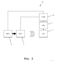
- the measuring system 10 comprises a measuring device 1, a measuring antenna 3 connected to the measuring device 1 by a coaxial cable 2 and a device under test mount 4.
- the device under test mount 4 holds a communication device under test 5.
- the device under test 5 comprises an antenna-array, which is though not depicted in detail here. By adjusting the antenna characteristic of the antenna-array, different antenna characteristics and thereby maximum gain directions 6 of the antenna-array can be set.
- the device under test 5 When performing a transmission measurement, the device under test 5 transmits a measuring signal using a presently set antenna characteristic and thereby a presently set maximum gain direction 6.
- the measuring signal is received by the measuring antenna 3 and handed on to the measuring device 1 via the coaxial cable 2.
- the measuring device 1 is for example a signal analyzer.
- the measuring device For performing a reception measurement, the measuring device 1, in this case for example a signal generator, generates a measuring signal and hands it to the measuring antenna 3 via the coaxial cable 2.
- the measuring antenna 3 transmits the measuring signal to the device under test 5, which receives it.
- the antenna characteristic of the antenna-array of the device under test 5 also influences the reception of the measuring signal from the measuring antenna 3.
- the device under test mount 4 and the measuring antenna 3 are located in fixed positions with regard to each other. This allows for a very simple hardware setup.
- the device under test mount 4 though is rotatable around at least one axis, preferably around two axes. It is thereby possible to rotate the device under test 5 so that the maximum gain direction 6 of the antenna-array points towards the measuring antenna 3 at all times. Details of this function are explained lateron, especially with regard to Fig. 4a - 4d .
- a second embodiment of the inventive measuring system 10 is depicted.
- a block-diagram is shown.
- the control unit 20 is adapted to control the function of the device under test 5 and the device under test mount 4.
- control unit 20 controls the function of the measuring device 1. Since here, a transmission measurement is performed, the device under test 5 is instructed by the control unit 20 to emit a measuring signal, which is then received by the measuring antenna 3 and further processed by the measuring device 1, which in this case for example is a signal analyzer. Moreover, the control unit 20 controls the device under test mount 4 to rotate the device under test 5 as required.
- a third embodiment of the inventive measuring system 10 is shown.
- the measuring system 10 is configured for performing a reception measurement by the device under test 5.
- the control unit 20 controls the measuring device 1, which in this case can for example be a signal generator, to generate a measuring signal and transmit it to the device under test 5 using the measuring antenna 3.
- the control unit 20 controls the device under test 5 to receive the measuring signal.
- the control unit 20 controls the device under test mount 4, as required.
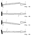
- FIG. 4a an initial situation after placing a device under test 5 on the device under test mount 4 is shown.
- the device under test 5 is set to a certain antenna characteristic resulting in a maximum gain direction 61 of the antenna-array.
- the set maximum gain direction 61 of the antenna-array is not in alignment with the direction of the measuring antenna 3.
- the device under test mount 4 is rotated around at least one axis in order to align the set maximum gain direction 61 with the direction of the measuring antenna 3. In case of a transmission measurement, this is done by iteratively rotating the device under test mount and measuring the reception power received by the measuring antenna 3. When a maximum reception power is reached, an alignment of the set maximum gain direction 61 with the direction of the measuring antenna 3 is achieved. This is depicted in Fig. 4b .
- a further antenna characteristic of the antenna-array is set.
- the set maximum gain direction 62 of the antenna-array is changed to the maximum gain direction 63 as depicted in Fig. 4c .
- the device under test mount is now rotated by the exact same amount into the opposite direction resulting in a rotation of the maximum gain direction 64 as depicted in Fig. 4d .
- the maximum gain direction 64 is now perfectly in alignment with the measuring antenna 3. In practice, this is though not necessarily the case.
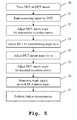
- a transmission measurement is described.
- a device under test is placed on a device under test mount.
- a measuring signal is emitted by the device under test.
- the device under test mount angle is adjusted by rotating the device under test mount for a maximal reception power by the measuring antenna.
- an antenna characteristic of the antenna-array of the device under test is adjusted by an angle ⁇ , especially a beamforming angle is adjusted.
- the device under test mount is rotated by the angle ⁇ into the opposite direction.
- a sixth step 55 again the device under test mount is rotated to achieve maximum reception power.
- a seventh step 56 as a measuring result, a maximum gain direction misalignment is determined as a measuring result by subtracting the set maximum gain direction and the present maximum gain direction determined in the sixth step 55.
- additional measurements can be performed on the device under test at this position of maximum gain direction of the measuring antenna. Thereby, reproducible measuring conditions can be achieved every time a device under test is measured.
- a reception measurement is described.
- a device under test is placed on a device under test mount.
- a measuring signal is emitted by a measuring device and received by the device under test.
- the device under test mount is rotated to adjust a device under test mount angle for maximal reception power. This reception power is detected by the device under test itself.
- the antenna characteristic of the device under test is adjusted resulting in a rotation of a set maximum gain direction of the antenna-array by an angle of ⁇ .
- the device under test mount is rotated in the opposite direction by the angle ⁇ .
- a measuring result is determined by determining a maximum gain direction misalignment by calculating the difference between the set maximum gain direction and the present maximum gain direction. Also here, in an optional eighth step 67, further measurements can now be performed on the device under test.
- the invention is not limited to the examples shown above. Especially it is not limited to mobile telephones or base stations. Any communication device, which comprises a plurality of antennas grouped in an antenna-array can be used as a device under test. Also the measuring device described above is not limited to the examples of signal generator and signal analyzer. Also other measuring devices can be used. The characteristics of the exemplary embodiments can be used in any advantageous combination.
Abstract
Description
- The invention relates to a system and method for measuring for communication devices comprising antenna-arrays, especially antenna-arrays used for beamforming.
- After successfully introducing the long term evolution LTE technology and first significant improvements (LTE-A) the next mobile communications technology 5G is imminent. Regarding 5G, a move to even higher frequencies and larger bandwidths are to be expected. Although the exact frequency bands are not yet specified, frequencies up to 75 GHz are in discussion. For reaching sufficient ranges using these frequencies, the antenna technology is a core aspect. High antenna gains are necessary. In order to reach such high antenna gains, the use of antennas with a large number of radiating elements, especially antenna-arrays are in discussion.
- With increasing frequency, the physical area required for such phased arrays continuously decreases and allows a high integration of respective solutions. Therefore, more attention has to be given to testing the antenna diagrams/beams than with today's technology. Especially, a dynamic adaptation has to be checked. Also, according measurements are so far performed by using network analyzers connected by coaxial cables to the device under test. When using highly integrated active antennas, this interface though is potentially not available anymore.
- So far, when testing devices under test in a lab environment, measuring devices are connected via physical cables with the device under test. This results in a stable and reproducible measurement environment. The antenna is so far hardly ever used in these measurements. The test of the antenna implementation is usually performed in a separate measurement.
- In 5G technology though, the active antenna will be an integral part of the device under test. Parameters as output power, neighbor channel influence, and modulation accuracy can only be accurately measured taking the antenna into account. Especially, the antenna diagram resulting in the maximum gain direction of the respective antenna-array has to be taken into account.
- The document
US 2013/0093447 A1 shows a measuring system for performing over-the-air measurements on devices under test. The respective device under test is placed within a device under test holder, which is rotatable by a device under test a rotator. Using a single fixed measuring antenna, measurements are performed. The measuring system according toUS 2013/0093447 A1 though does not take devices under test using antenna-arrays, beamforming, antenna diagrams and maximum gain directions of an antenna-array into account. It is therefore not possible to perform accurate measurements on future generations of devices under test using the measuring system. -
Documents EP 2 354 801 A1 undDE 10 2006 045 645 A1 show respective holders for testing mobile phones. - Accordingly, the object of the present invention is to provide a measuring system and measuring method for performing accurate measurements on communication devices comprising antenna-arrays.
- The object is solved by the features of
claim 1 for the system and claim 10 for the method. Further developments are contained by the dependent claims. - According to a first aspect of the invention, a measuring system for measuring a communication device under test is provided. The measuring system comprises a control unit, a measuring device, at least one measuring antenna and a device under test mount. The at least one measuring antenna is advantageously mounted in a fixed location and orientation regarding the device under test mount. The device under test mount is adapted to hold the device under test and rotate the device under test around at least one axis.
- The measuring system is furthermore adapted for measuring a communication device under test comprising an antenna-array. A control unit is adapted to set an antenna characteristic of the antenna-array of the device under test, whereby adjusting a set maximum gain direction of the antenna-array.
- Preferably, the control unit is adapted to instruct the device under test mount to rotate the communication device under test compensating for the set maximum gain direction of the antenna-array, so that the set maximum gain direction of the antenna-array meets a direction of the measuring antenna regarding the device under test.
- Further preferably, the control unit is adapted to determine an actual maximum gain direction of the antenna-array by iteratively instructing the device under test mount to rotate the device under test to determine a present gain of the antenna-array, and to determining the actual maximum gain direction as a rotation direction of the device under test mount of maximal gain. It is thus possible to accurately determine the function of setting the antenna characteristics and the maximum gain direction of the antenna-array with a low hardware effort.
- Advantageously, the control unit is adapted to determine a maximum gain misalignment as a measuring result by determining a difference between the set maximum gain direction of the antenna-array and the actual maximum gain direction of the antenna-array. Thereby, a very simple parameter is generated for determining the quality of an antenna-array adjustment.
- Furthermore, advantageously the control unit is adapted to determine the actual maximum gain direction of the antenna-array by respectively after instructing the device under test mount to rotate the device under test and determining a present gain of the antenna-array, determining a gain-difference of the present gain regarding a directly previous gain, reversing a direction of rotating the device under test for a following iteration, if the gain difference is negative and above a first pre-specified threshold, reducing a rotation amount for a following iteration, if the gain difference is positive and below a second pre-specified threshold and/or determining the actual maximum gain direction of the antenna-array as a present direction, if the gain difference is below the first pre-specified threshold. It is thus possible to very efficiently determine the actual maximum gain direction of the antenna-array. Advantageously, for a reception measurement, the measuring system comprises a signal generator adapted to generate a measuring signal. The measuring antenna is then adapted to transmit the measuring signal generated by the signal generator to the device under test. It is thus possible to perform reception measurements with the measuring system with minimal effort.
- Advantageously, the control unit is adapted to determine the present gain of the antenna-array by respectively instructing the device under test to measure a reception power of the measuring signal and comparing the reception power to a transmission power of the measuring signal. A very efficient determining of the present gain of the antenna-array is thereby possible.
- Alternatively, for a transmission measurement, the measuring system comprises a signal analyzer. The control unit is then adapted to instruct the communication device under test to generate a measuring signal and transmitted to the measuring antenna. The signal analyzer is adapted to receive the measuring signal. It is thereby possible to very efficiently to perform a transmission measurement.
- Advantageously, the control unit is adapted to determine the present gain of the antenna-array by respectively instructing the signal analyzer to measure a reception power of the measuring signal and by comparing the reception power to a transmission power of the measuring signal. A very efficient determining of the present gain of the antenna-array is thereby possible.
- Advantageously, the device under test mount is adapted to rotate the device under test around to axes. Thereby, a three-dimensional measuring is possible.
- According to a second aspect of the invention, a measuring method for performing measurements on a communication device under test having an antenna-array, is provided.
- The measuring method advantageously comprises positioning at least one measuring antenna in a fixed location and orientation regarding a device under test mount and positioning the communication device under test in the device under test mount. The measuring method further comprises setting an antenna characteristic of the antenna-array of the communication device under test thereby adjusting a set maximum gain direction of the antenna-array.
- Preferably, the method comprises the step of rotating the communication device under test using the device under test mount and compensating for the set maximum gain direction of the antenna-array, so that the set maximum gain direction of the antenna-array meets a direction of the measuring antenna regarding the device under test.
- Also the method preferably comprises determining an actual maximum gain direction of the antenna-array by iteratively rotating the communication device under test using the device under test mount, determining a present gain of the antenna-array and determining the actual maximum gain direction as a rotation direction of the device under test mount of maximal gain. Thereby, a very efficient determining of the characteristics of the device under test is possible.
- An exemplary embodiment of the invention is now further explained with respect to the drawings, by way of example only. In the drawings
- Fig. 1
- shows a first embodiment of the inventive measuring system in a three-dimensional overview;
- Fig. 2
- shows a second embodiment of the inventive measuring system, especially in a configuration for performing a transmission measurement, in a block diagram;
- Fig. 3
- shows a third embodiment of the inventive measuring system, especially in a configuration for performing a reception measurement, in a block diagram;
- Fig. 4a
- shows a fourth embodiment of the inventive measuring system in a first step of performing a measurement, in a two-dimensional overview;
- Fig. 4b
- shows a fourth embodiment of the inventive measuring system in a second step of performing a measurement, in a two-dimensional overview;
- Fig. 4c
- shows a fourth embodiment of the inventive measuring system in a third step of performing a measurement, in a two-dimensional overview;
- Fig. 4d
- shows a fourth embodiment of the inventive measuring system in a fourth step of performing a measurement, in a two-dimensional overview;
- Fig. 5
- shows a first embodiment of the measuring method according to the invention, especially for performing a transmission measurement, in a flow diagram, and
- Fig. 6
- shows a second embodiment of the measuring method according to the invention, especially for performing a reception measurement, in a flow diagram.
- First we demonstrate the general construction and function of different embodiments of the measuring system along
Fig. 1 - Fig. 3 . AlongFig. 4a - Fig. 4d a typical measurement is described in detail. Finally, alongFig. 5 andFig. 6 different embodiments of the inventive method are described. Similar entities and reference numbers have been partially omitted. - In
Fig. 1 , a first embodiment of theinventive measuring system 10 is shown. The measuringsystem 10 comprises ameasuring device 1, a measuringantenna 3 connected to themeasuring device 1 by acoaxial cable 2 and a device undertest mount 4. The device undertest mount 4 holds a communication device undertest 5. The device undertest 5 comprises an antenna-array, which is though not depicted in detail here. By adjusting the antenna characteristic of the antenna-array, different antenna characteristics and therebymaximum gain directions 6 of the antenna-array can be set. - When performing a transmission measurement, the device under
test 5 transmits a measuring signal using a presently set antenna characteristic and thereby a presently setmaximum gain direction 6. The measuring signal is received by the measuringantenna 3 and handed on to themeasuring device 1 via thecoaxial cable 2. In this case, the measuringdevice 1 is for example a signal analyzer. - For performing a reception measurement, the measuring
device 1, in this case for example a signal generator, generates a measuring signal and hands it to the measuringantenna 3 via thecoaxial cable 2. The measuringantenna 3 transmits the measuring signal to the device undertest 5, which receives it. The antenna characteristic of the antenna-array of the device undertest 5 also influences the reception of the measuring signal from the measuringantenna 3. - The device under
test mount 4 and the measuringantenna 3 are located in fixed positions with regard to each other. This allows for a very simple hardware setup. The device undertest mount 4 though is rotatable around at least one axis, preferably around two axes. It is thereby possible to rotate the device undertest 5 so that themaximum gain direction 6 of the antenna-array points towards the measuringantenna 3 at all times. Details of this function are explained lateron, especially with regard toFig. 4a - 4d . - In
Fig. 2 , a second embodiment of theinventive measuring system 10, especially in a configuration for performing a transmission measurement, is depicted. Here, a block-diagram is shown. In addition to the components already described alongFig. 1 , here acontrol unit 20 is present. Thecontrol unit 20 is adapted to control the function of the device undertest 5 and the device undertest mount 4. - Also the
control unit 20 controls the function of the measuringdevice 1. Since here, a transmission measurement is performed, the device undertest 5 is instructed by thecontrol unit 20 to emit a measuring signal, which is then received by the measuringantenna 3 and further processed by the measuringdevice 1, which in this case for example is a signal analyzer. Moreover, thecontrol unit 20 controls the device undertest mount 4 to rotate the device undertest 5 as required. - In
Fig. 3 , a third embodiment of theinventive measuring system 10 is shown. In this embodiment, the measuringsystem 10 is configured for performing a reception measurement by the device undertest 5. Thecontrol unit 20 controls the measuringdevice 1, which in this case can for example be a signal generator, to generate a measuring signal and transmit it to the device undertest 5 using the measuringantenna 3. Moreover, thecontrol unit 20 controls the device undertest 5 to receive the measuring signal. Also, thecontrol unit 20 controls the device undertest mount 4, as required. - Along
Fig. 4a - Fig. 4d , the progress of a typical measurement using a further embodiment of the inventive measuring system is shown. InFig. 4a , an initial situation after placing a device undertest 5 on the device undertest mount 4 is shown. The device undertest 5 is set to a certain antenna characteristic resulting in amaximum gain direction 61 of the antenna-array. At present, the setmaximum gain direction 61 of the antenna-array is not in alignment with the direction of the measuringantenna 3. - In a first step, the device under
test mount 4 is rotated around at least one axis in order to align the setmaximum gain direction 61 with the direction of the measuringantenna 3. In case of a transmission measurement, this is done by iteratively rotating the device under test mount and measuring the reception power received by the measuringantenna 3. When a maximum reception power is reached, an alignment of the setmaximum gain direction 61 with the direction of the measuringantenna 3 is achieved. This is depicted inFig. 4b . - Now, in a second step, in order to test the accuracy of the setting of the antenna characteristics and thereby of the setting of the maximum gain direction of the antenna-array, a further antenna characteristic of the antenna-array is set. Thereby, the set
maximum gain direction 62 of the antenna-array is changed to themaximum gain direction 63 as depicted inFig. 4c . In a third step, the device under test mount is now rotated by the exact same amount into the opposite direction resulting in a rotation of themaximum gain direction 64 as depicted inFig. 4d . In an optimal case of ideal functioning of the antenna characteristic adjustment, themaximum gain direction 64 is now perfectly in alignment with the measuringantenna 3. In practice, this is though not necessarily the case. Therefore, now again an iterative detection of the maximum gain direction is performed by again rotating the device under test mount and thereby the device undertest 5, until an optimal alignment of themaximum gain direction 64 with the measuringantenna 3 is achieved. The resulting additional rotation angle of the device under test mount and the device undertest 5 corresponds to a maximum gain misalignment, which can be used as a measuring result. - Additional measurement can now be performed on the device under
test 5. - In
Fig. 5 a first embodiment of the inventive measuring method is shown. Here, a transmission measurement is described. In afirst step 50, a device under test is placed on a device under test mount. In asecond step 51, a measuring signal is emitted by the device under test. In athird step 52, the device under test mount angle is adjusted by rotating the device under test mount for a maximal reception power by the measuring antenna. In afourth step 53, an antenna characteristic of the antenna-array of the device under test is adjusted by an angle α, especially a beamforming angle is adjusted. In afifth step 54, the device under test mount is rotated by the angle α into the opposite direction. - In a
sixth step 55, again the device under test mount is rotated to achieve maximum reception power. In aseventh step 56, as a measuring result, a maximum gain direction misalignment is determined as a measuring result by subtracting the set maximum gain direction and the present maximum gain direction determined in thesixth step 55. In an optionaleighth step 57, additional measurements can be performed on the device under test at this position of maximum gain direction of the measuring antenna. Thereby, reproducible measuring conditions can be achieved every time a device under test is measured. - As an alternative, in
Fig. 6 , a reception measurement is described. In afirst step 60, a device under test is placed on a device under test mount. In asecond step 61, a measuring signal is emitted by a measuring device and received by the device under test. In athird step 62, the device under test mount is rotated to adjust a device under test mount angle for maximal reception power. This reception power is detected by the device under test itself. In afourth step 63, the antenna characteristic of the device under test is adjusted resulting in a rotation of a set maximum gain direction of the antenna-array by an angle of α. In afifth step 64, the device under test mount is rotated in the opposite direction by the angle α. - In a
sixth step 65, again the device under test mount is rotated in order to maximize the reception power by the device under test. A present maximum gain direction is thereby determined. In aseventh step 66, a measuring result is determined by determining a maximum gain direction misalignment by calculating the difference between the set maximum gain direction and the present maximum gain direction. Also here, in an optionaleighth step 67, further measurements can now be performed on the device under test. - The invention is not limited to the examples shown above. Especially it is not limited to mobile telephones or base stations. Any communication device, which comprises a plurality of antennas grouped in an antenna-array can be used as a device under test. Also the measuring device described above is not limited to the examples of signal generator and signal analyzer. Also other measuring devices can be used. The characteristics of the exemplary embodiments can be used in any advantageous combination.
Claims (17)
- Measuring system (10), for measuring a communication device under test (5), comprising a control unit (20), a measuring device (1), at least one measuring antenna (3), and a device under test mount (4),
wherein the device under test mount (4) is adapted to hold the communication device under test (5) and to rotate the communication device under test (5) around at least one axis,
characterized in that
the measuring system (10) is adapted for measuring a communication device under test (5) comprising an antenna-array, wherein the control unit (20) is adapted to set an antenna characteristic of the antenna-array of the communication device under test (5), thereby adjusting a set maximum gain direction of the antenna-array. - Measuring system according to claim 1,
wherein the control unit (20) is adapted to- instruct the device under test mount (4) to rotate the communication device under test (5) compensating for the set maximum gain direction of the antenna-array, so that the set maximum gain direction of the antenna-array meets a direction of the measuring antenna (3) regarding the communication device under test (5), and- determine an actual maximum gain direction of the antenna-array by iteratively instructing the device under test mount (4) to rotate the communication device under test (5), determining a present gain of the antenna-array, and determining the actual maximum gain direction as a rotation direction of the device under test mount (4) of maximal gain. - Measuring system according to claim 2,
characterized in that
the control unit (20) is adapted to determine a maximum gain misalignment as a measuring result by determining a difference between the set maximum gain direction of the antenna-array and the actual maximum gain direction of the antenna-array. - Measuring system according to claim 2 or 3,
characterized in that
the control unit (20) is adapted to determine the actual maximum gain direction of the antenna-array by, respectively after instructing the device under test mount (4) to rotate the communication device under test (5) and determining a present gain of the antenna-array,- determining, a gain difference of the present gain regarding a directly previous present gain,- reversing a direction of rotating the communication device under test (5) for a following iteration, if the gain difference is negative and above a first pre-specified threshold, and/or- reducing a rotation amount for a following iteration, if the gain difference is positive and below a second pre-specified threshold, and/or- determining the actual maximum gain direction of the antenna-array as the present direction, if the gain difference is below the first pre-specified threshold. - Measuring system according to any of the claims 1 to 4,
characterized in that
for a reception measurement,- the measuring device (1) is a signal generator adapted to generate a measuring signal, and- the measuring antenna (3) is adapted to transmit the measuring signal generated by the signal generator to the communication device under test (5). - Measuring system according to claim 5,
characterized in that
the control unit (20) is adapted to determine the present gain of the antenna-array by- respectively instructing the communication device under test (5) to measure a reception power of the measuring signal, and- comparing the reception power to a transmission power of the measuring signal. - Measuring system according to any of the claims 1 to 4,
characterized in that
for a transmission measurement,- the measuring device (1) is a signal analyzer,- the control unit (20) is adapted to instruct the communication device under test (5) to generate a measuring signal and transmit it to the measuring antenna (3), and- the signal analyzer is adapted to receive the measuring signal. - Measuring system according to claim 7,
characterized in that
the control unit (20) is adapted to determine the present gain of the antenna-array by- respectively instructing the signal analyzer to measure a reception power of the measuring signal, and- comparing the reception power to a transmission power of the measuring signal. - Measuring system according to any of the claims 1 to 8,
characterized in that
wherein the device under test mount (4) is adapted to rotate the communication device under test (5) around two axes. - Measuring method, for measuring a communication device under test (5), comprising the step:- positioning (50, 60) the communication device under test (5) in the device under test mount (4),
characterized in that
the measuring method measures a communication device comprising an antenna-array,
wherein the method further comprises the step:- setting (53, 63) an antenna characteristic of the antenna-array of the communication device under test (5), thereby adjusting a set maximum gain direction of the antenna-array. - Measuring method according to claim 10,
characterized in that
the method further comprises the steps:- rotating (54, 64) the communication device under test (5) using the device under test mount (4), compensating for the set maximum gain direction of the antenna-array, so that the set maximum gain direction of the antenna-array meets a direction of the measuring antenna (3) regarding the communication device under test (5), and- determining (55, 65) an actual maximum gain direction of the antenna-array by iteratively rotating the communication device under test (5) using the device under test mount (4), determining a present gain of the antenna-array, and determining the actual maximum gain direction as a rotation direction of the device under test mount (4) of maximal gain. - Measuring method according to claim 11,
characterized in that
the method comprises determining (56, 66) a maximum gain misalignment as a measuring result by determining a difference between the set maximum gain direction of the antenna-array and the actual maximum gain direction of the antenna-array. - Measuring method according to claim 11 or 12,
characterized in that
the determining of the actual maximum gain direction of the antenna-array comprises, respectively after rotating the communication device under test (5) and determining the present gain of the antenna-array,- determining, a gain difference of the present gain regarding a directly previous present gain,- reversing a direction of rotating the communication device under test (5) for a following iteration, if the gain difference is negative and above a first pre-specified threshold,- reducing a rotation amount for a following iteration, if the gain difference is positive and below a second pre-specified threshold, and- determining the actual maximum gain direction of the antenna-array as a present direction, if the gain difference below the first pre-specified threshold. - Measuring method according to any of the claims 10 to 13,
characterized in that
for a reception measurement, the method comprises:- generating (61) a measuring signal by a signal generator, and- transmitting (61) the measuring signal generated by the signal generator to the device under test by the measuring antenna (3). - Measuring method according to claim 14,
characterized in that
the determining of the present gain of the antenna-array comprises:- respectively measuring a reception power of the measuring signal, and- comparing the reception power to a transmission power of the measuring signal. - Measuring method according to any of the claims 10 to 13,
characterized in that
for a transmission measurement, the method comprises:- instructing the device under test to generate (51) a measuring signal and transmit it to the measuring antenna (3), and- receiving the measuring signal using the measuring antenna (3) and a signal analyzer. - Measuring method according to claim 16,
characterized in that
the determining the present gain of the antenna-array comprises:- respectively measuring a reception power of the measuring signal by the signal analyzer, and- comparing the reception power to a transmission power of the measuring signal.
Priority Applications (2)
| Application Number | Priority Date | Filing Date | Title |
|---|---|---|---|
| EP15170968.0A EP3104539B1 (en) | 2015-06-08 | 2015-06-08 | Measuring system and measuring method for measuring devices under test with antenna-arrays |
| US15/171,928 US9780890B2 (en) | 2015-06-08 | 2016-06-02 | Wireless measuring system and method for measurement of a device under test with an antenna-array, considering maximum gain direction of the antenna array |
Applications Claiming Priority (1)
| Application Number | Priority Date | Filing Date | Title |
|---|---|---|---|
| EP15170968.0A EP3104539B1 (en) | 2015-06-08 | 2015-06-08 | Measuring system and measuring method for measuring devices under test with antenna-arrays |
Publications (2)
| Publication Number | Publication Date |
|---|---|
| EP3104539A1 true EP3104539A1 (en) | 2016-12-14 |
| EP3104539B1 EP3104539B1 (en) | 2017-09-13 |
Family
ID=53298252
Family Applications (1)
| Application Number | Title | Priority Date | Filing Date |
|---|---|---|---|
| EP15170968.0A Active EP3104539B1 (en) | 2015-06-08 | 2015-06-08 | Measuring system and measuring method for measuring devices under test with antenna-arrays |
Country Status (2)
| Country | Link |
|---|---|
| US (1) | US9780890B2 (en) |
| EP (1) | EP3104539B1 (en) |
Cited By (8)
| Publication number | Priority date | Publication date | Assignee | Title |
|---|---|---|---|---|
| WO2018128950A3 (en) * | 2017-01-06 | 2018-09-27 | Intel IP Corporation | Ue testing system for rf characteristics for the new radio standard |
| WO2018219680A1 (en) * | 2017-05-31 | 2018-12-06 | Fraunhofer-Gesellschaft zur Förderung der angewandten Forschung e.V. | Apparatus, measurement system for testing an apparatus and methods for operating the same |
| EP3416311A1 (en) * | 2017-06-14 | 2018-12-19 | Rohde & Schwarz GmbH & Co. KG | Test system and test method |
| EP3432490A1 (en) * | 2017-07-21 | 2019-01-23 | Rohde & Schwarz GmbH & Co. KG | Measuring system with positioning system for beamforming measurements and measuring method |
| DE102018002512A1 (en) | 2018-03-27 | 2019-10-02 | Bundesrepublik Deutschland, vertreten durch das Bundesministerium der Verteidigung, vertreten durch das Bundesamt für Ausrüstung, Informationstechnik und Nutzung der Bundeswehr | Device for antenna measurement |
| WO2019243449A3 (en) * | 2018-06-22 | 2020-02-06 | Fraunhofer-Gesellschaft zur Förderung der angewandten Forschung e.V. | Method and measurement environment, apparatus to be tested |
| CN114339777A (en) * | 2020-09-29 | 2022-04-12 | 中国移动通信集团设计院有限公司 | Antenna parameter optimization method and device, electronic equipment and storage medium |
| EP4280480A1 (en) | 2022-05-18 | 2023-11-22 | FenztraQ GmbH | Apparatus, system and method for testing a communication device |
Families Citing this family (14)
| Publication number | Priority date | Publication date | Assignee | Title |
|---|---|---|---|---|
| US10085162B2 (en) * | 2016-07-22 | 2018-09-25 | Ets-Lindgren, Inc. | System and method for over-the-air testing of milli-meter wave and other beamforming technologies |
| US10063327B2 (en) * | 2016-12-20 | 2018-08-28 | National Chung Shan Institute Of Science And Technology | System and method for array antenna failure detection and antenna self-correction |
| US10333632B2 (en) * | 2017-04-03 | 2019-06-25 | Ets-Lindgren, Inc. | Method and system for testing beam forming capabilities of wireless devices |
| US10044104B1 (en) * | 2017-07-14 | 2018-08-07 | Rohde & Schwarz Gmbh & Co. Kg | Test arrangement and test method |
| US9991591B1 (en) * | 2017-07-20 | 2018-06-05 | Rohde & Schwarz Gmbh & Co. Kg | Test arrangement and test method for a beamsteered wireless device under test |
| US9991592B1 (en) | 2017-07-20 | 2018-06-05 | Rohde & Schwarz Gmbh & Co. Kg | Test arrangement and test method |
| US11035930B2 (en) * | 2017-07-26 | 2021-06-15 | Rohde & Schwarz Gmbh & Co. Kg | Antenna measurement system as well as method for controlling a measurement antenna array |
| US10256930B2 (en) * | 2017-08-21 | 2019-04-09 | Rohde & Schwarz Gmbh & Co. Kg | Testing methods and systems for mobile communication devices |
| US10397667B2 (en) * | 2017-09-28 | 2019-08-27 | Intel IP Corporation | Sensor position optimization by active flexible device housing |
| US11226360B2 (en) * | 2018-05-24 | 2022-01-18 | Rohde & Schwarz Gmbh & Co. Kg | Over-the-air test system and method with visual status indication |
| US10404384B1 (en) * | 2018-08-03 | 2019-09-03 | Rohde & Schwarz Gmbh & Co. Kg | System and method for testing a device under test within an anechoic chamber based on a minimum test criteria |
| US11764888B2 (en) * | 2019-06-07 | 2023-09-19 | Qualcomm Incorporated | Beam characterization |
| KR20230004586A (en) * | 2020-04-09 | 2023-01-06 | 프라운호퍼 게젤샤프트 쭈르 푀르데룽 데어 안겐반텐 포르슝 에. 베. | Beam correspondence parameter determination |
| DE102020123620A1 (en) | 2020-09-10 | 2022-03-10 | NOFFZ Technologies GmbH | Positioning unit, test device for testing an HF module and method for testing an HF module |
Citations (5)
| Publication number | Priority date | Publication date | Assignee | Title |
|---|---|---|---|---|
| DE102006045645A1 (en) | 2006-09-27 | 2008-04-03 | Rhode & Schwarz Gmbh & Co. Kg | antenna |
| US20110122032A1 (en) * | 2009-05-29 | 2011-05-26 | Tsutomu Sakata | Antenna evaluation apparatus and antenna evaluation method for creating different sets of multipath waves around receiving antenna |
| EP2354801A1 (en) | 2010-02-03 | 2011-08-10 | Rohde & Schwarz GmbH & Co. KG | Holding device and system for positioning a device for a wireless communication in a measurement environment |
| US20130093447A1 (en) | 2011-10-12 | 2013-04-18 | Joshua G. Nickel | Methods for Reducing Path Loss While Testing Wireless Electronic Devices with Multiple Antennas |
| WO2014086268A1 (en) * | 2012-12-03 | 2014-06-12 | Tri-L Solutions Inc. | Method and device for testing performance of wireless terminal |
Family Cites Families (11)
| Publication number | Priority date | Publication date | Assignee | Title |
|---|---|---|---|---|
| JPH05136622A (en) * | 1991-11-13 | 1993-06-01 | Mitsubishi Electric Corp | Phased array antenna phase measuring circuit |
| US5973638A (en) * | 1998-01-30 | 1999-10-26 | Micronetics Wireless, Inc. | Smart antenna channel simulator and test system |
| KR100713164B1 (en) * | 1999-01-30 | 2007-05-02 | 주식회사 세스텍 | Signal processing method of array antenna system for cdma mobile telecommunication network |
| US6636173B2 (en) * | 2001-12-20 | 2003-10-21 | Lockheed Martin Corporation | Calibration system and method for phased array antenna using near-field probe and focused null |
| EP1341326A1 (en) * | 2002-02-26 | 2003-09-03 | Alcatel | Link restoration in a fixed wireless transmission network |
| US8164521B2 (en) * | 2007-08-23 | 2012-04-24 | Marvell World Trade Ltd. | Pseudo-omni-directional beamforming with multiple narrow-band beams |
| US8325098B1 (en) * | 2010-04-29 | 2012-12-04 | United States Of America As Represented By The Secretary Of The Navy | Dynamic antenna pattern measurement method |
| WO2012167111A2 (en) * | 2011-06-02 | 2012-12-06 | Parkervision, Inc. | Antenna control |
| KR101675949B1 (en) * | 2012-03-22 | 2016-11-15 | 한국전자통신연구원 | Measurement method and apparatus for radiated power to antenna |
| US20140057570A1 (en) * | 2012-08-23 | 2014-02-27 | Siklu Communication ltd. | Systems and methods for optimizing communication performance |
| US20170187109A1 (en) * | 2015-12-29 | 2017-06-29 | James June-Ming Wang | Final fabrication and calibration steps for hierarchically elaborated phased-array antenna and subarray manufacturing process |
-
2015
- 2015-06-08 EP EP15170968.0A patent/EP3104539B1/en active Active
-
2016
- 2016-06-02 US US15/171,928 patent/US9780890B2/en active Active
Patent Citations (5)
| Publication number | Priority date | Publication date | Assignee | Title |
|---|---|---|---|---|
| DE102006045645A1 (en) | 2006-09-27 | 2008-04-03 | Rhode & Schwarz Gmbh & Co. Kg | antenna |
| US20110122032A1 (en) * | 2009-05-29 | 2011-05-26 | Tsutomu Sakata | Antenna evaluation apparatus and antenna evaluation method for creating different sets of multipath waves around receiving antenna |
| EP2354801A1 (en) | 2010-02-03 | 2011-08-10 | Rohde & Schwarz GmbH & Co. KG | Holding device and system for positioning a device for a wireless communication in a measurement environment |
| US20130093447A1 (en) | 2011-10-12 | 2013-04-18 | Joshua G. Nickel | Methods for Reducing Path Loss While Testing Wireless Electronic Devices with Multiple Antennas |
| WO2014086268A1 (en) * | 2012-12-03 | 2014-06-12 | Tri-L Solutions Inc. | Method and device for testing performance of wireless terminal |
Cited By (18)
| Publication number | Priority date | Publication date | Assignee | Title |
|---|---|---|---|---|
| US10880020B2 (en) | 2017-01-06 | 2020-12-29 | Apple Inc. | UE testing system for RF characteristics for the new radio standard |
| WO2018128950A3 (en) * | 2017-01-06 | 2018-09-27 | Intel IP Corporation | Ue testing system for rf characteristics for the new radio standard |
| CN110999136B (en) * | 2017-05-31 | 2022-06-24 | 弗劳恩霍夫应用研究促进协会 | Device, measurement system for testing device and operation method thereof |
| CN115225169A (en) * | 2017-05-31 | 2022-10-21 | 弗劳恩霍夫应用研究促进协会 | Device, measurement system for testing a device and method of operating the same |
| CN110999136A (en) * | 2017-05-31 | 2020-04-10 | 弗劳恩霍夫应用研究促进协会 | Device, measurement system for testing device and operation method thereof |
| US11770195B2 (en) | 2017-05-31 | 2023-09-26 | Fraunhofer-Gesellschaft zur Förderung der angewandten Forschung e.V. | Apparatus, measurement system for testing an apparatus and methods for operating the same |
| EP4044461A3 (en) * | 2017-05-31 | 2022-11-02 | Fraunhofer-Gesellschaft zur Förderung der angewandten Forschung e.V. | Apparatus, measurement system for testing an apparatus and methods for operating the same |
| US11343002B2 (en) | 2017-05-31 | 2022-05-24 | Fraunhofer-Gesellschaft zur Förderung der angewandten Forschung e.V. | Apparatus, measurement system for testing an apparatus and methods for operating the same |
| WO2018219680A1 (en) * | 2017-05-31 | 2018-12-06 | Fraunhofer-Gesellschaft zur Förderung der angewandten Forschung e.V. | Apparatus, measurement system for testing an apparatus and methods for operating the same |
| CN109085431A (en) * | 2017-06-14 | 2018-12-25 | 罗德施瓦兹两合股份有限公司 | Test macro and test method |
| EP3416311A1 (en) * | 2017-06-14 | 2018-12-19 | Rohde & Schwarz GmbH & Co. KG | Test system and test method |
| EP3432490A1 (en) * | 2017-07-21 | 2019-01-23 | Rohde & Schwarz GmbH & Co. KG | Measuring system with positioning system for beamforming measurements and measuring method |
| DE102018002512A1 (en) | 2018-03-27 | 2019-10-02 | Bundesrepublik Deutschland, vertreten durch das Bundesministerium der Verteidigung, vertreten durch das Bundesamt für Ausrüstung, Informationstechnik und Nutzung der Bundeswehr | Device for antenna measurement |
| WO2019243449A3 (en) * | 2018-06-22 | 2020-02-06 | Fraunhofer-Gesellschaft zur Förderung der angewandten Forschung e.V. | Method and measurement environment, apparatus to be tested |
| JP2021528650A (en) * | 2018-06-22 | 2021-10-21 | フラウンホーファー−ゲゼルシャフト・ツール・フェルデルング・デル・アンゲヴァンテン・フォルシュング・アインゲトラーゲネル・フェライン | Method, measurement environment and equipment under test |
| CN114339777A (en) * | 2020-09-29 | 2022-04-12 | 中国移动通信集团设计院有限公司 | Antenna parameter optimization method and device, electronic equipment and storage medium |
| CN114339777B (en) * | 2020-09-29 | 2023-12-15 | 中国移动通信集团设计院有限公司 | Antenna parameter optimization method and device, electronic equipment and storage medium |
| EP4280480A1 (en) | 2022-05-18 | 2023-11-22 | FenztraQ GmbH | Apparatus, system and method for testing a communication device |
Also Published As
| Publication number | Publication date |
|---|---|
| US9780890B2 (en) | 2017-10-03 |
| EP3104539B1 (en) | 2017-09-13 |
| US20160359573A1 (en) | 2016-12-08 |
Similar Documents
| Publication | Publication Date | Title |
|---|---|---|
| EP3104539B1 (en) | Measuring system and measuring method for measuring devices under test with antenna-arrays | |
| EP3683984B1 (en) | Array antenna calibration method and device | |
| CN108966264B (en) | System and method for performing over-the-air testing for large-scale multiple-input multiple-output wireless systems | |
| CN109791171B (en) | Reduced mesh for total radiated power measurement | |
| EP3497826B1 (en) | Methods for over-the-air testing of base station receiver sensitivity | |
| CN109155984B (en) | Method for determining channel time delay, positioning method and related equipment | |
| US10393786B2 (en) | Test system and method for over the air (OTA) measurements based on randomly adjusted measurement points | |
| WO2018128950A3 (en) | Ue testing system for rf characteristics for the new radio standard | |
| EP3462190B1 (en) | Measurement system and method for performing test measurements | |
| EP3348009B1 (en) | Method and device for enabling testing of a communication node | |
| CN111641463B (en) | Phased array antenna calibration method, phased array antenna calibration device, computer equipment and storage medium | |
| US9954279B1 (en) | Test system and test method | |
| EP2173005B1 (en) | Improved probe calibration for an active antenna | |
| CN109661029B (en) | Method, apparatus and computer readable medium for determining a location of a communication device | |
| KR20120059858A (en) | Apparatus and method for detecting effective radiated power | |
| CN107817391B (en) | TIS rapid measurement method | |
| Pelham et al. | Non-intrusive characterization of 60GHz antenna array, using packet measurements | |
| EP4309309A1 (en) | Method and network node for over-the-air testing of an active antenna system | |
| US11337089B2 (en) | Method and nodes for testing a node | |
| KR102308079B1 (en) | RRH(Remote Radio Head) Voltage Standing Wave Ratio (VSWR) of the terminal considering a power control system and method for improving accuracy | |
| JP7382430B2 (en) | Antenna device and performance test method | |
| EP4145146A1 (en) | Measurement method and measurement system | |
| US20230327784A1 (en) | Over-the-air based estimation of phase accuracy of a radio transceiver device | |
| Aydin et al. | The Effects of the Use of DRx Antenna Structure on the Rx Performance of Smartphones | |
| CN117135559A (en) | Method, device, equipment and storage medium for detecting antenna azimuth angle |
Legal Events
| Date | Code | Title | Description |
|---|---|---|---|
| PUAI | Public reference made under article 153(3) epc to a published international application that has entered the european phase |
Free format text: ORIGINAL CODE: 0009012 |
|
| STAA | Information on the status of an ep patent application or granted ep patent |
Free format text: STATUS: REQUEST FOR EXAMINATION WAS MADE |
|
| 17P | Request for examination filed |
Effective date: 20151130 |
|
| AK | Designated contracting states |
Kind code of ref document: A1 Designated state(s): AL AT BE BG CH CY CZ DE DK EE ES FI FR GB GR HR HU IE IS IT LI LT LU LV MC MK MT NL NO PL PT RO RS SE SI SK SM TR |
|
| AX | Request for extension of the european patent |
Extension state: BA ME |
|
| GRAP | Despatch of communication of intention to grant a patent |
Free format text: ORIGINAL CODE: EPIDOSNIGR1 |
|
| STAA | Information on the status of an ep patent application or granted ep patent |
Free format text: STATUS: GRANT OF PATENT IS INTENDED |
|
| INTG | Intention to grant announced |
Effective date: 20170228 |
|
| GRAS | Grant fee paid |
Free format text: ORIGINAL CODE: EPIDOSNIGR3 |
|
| GRAA | (expected) grant |
Free format text: ORIGINAL CODE: 0009210 |
|
| STAA | Information on the status of an ep patent application or granted ep patent |
Free format text: STATUS: THE PATENT HAS BEEN GRANTED |
|
| AK | Designated contracting states |
Kind code of ref document: B1 Designated state(s): AL AT BE BG CH CY CZ DE DK EE ES FI FR GB GR HR HU IE IS IT LI LT LU LV MC MK MT NL NO PL PT RO RS SE SI SK SM TR |
|
| REG | Reference to a national code |
Ref country code: GB Ref legal event code: FG4D |
|
| REG | Reference to a national code |
Ref country code: CH Ref legal event code: EP |
|
| REG | Reference to a national code |
Ref country code: IE Ref legal event code: FG4D |
|
| REG | Reference to a national code |
Ref country code: AT Ref legal event code: REF Ref document number: 929120 Country of ref document: AT Kind code of ref document: T Effective date: 20171015 |
|
| REG | Reference to a national code |
Ref country code: DE Ref legal event code: R096 Ref document number: 602015004602 Country of ref document: DE |
|
| REG | Reference to a national code |
Ref country code: NL Ref legal event code: MP Effective date: 20170913 |
|
| REG | Reference to a national code |
Ref country code: LT Ref legal event code: MG4D |
|
| PG25 | Lapsed in a contracting state [announced via postgrant information from national office to epo] |
Ref country code: LT Free format text: LAPSE BECAUSE OF FAILURE TO SUBMIT A TRANSLATION OF THE DESCRIPTION OR TO PAY THE FEE WITHIN THE PRESCRIBED TIME-LIMIT Effective date: 20170913 Ref country code: FI Free format text: LAPSE BECAUSE OF FAILURE TO SUBMIT A TRANSLATION OF THE DESCRIPTION OR TO PAY THE FEE WITHIN THE PRESCRIBED TIME-LIMIT Effective date: 20170913 Ref country code: HR Free format text: LAPSE BECAUSE OF FAILURE TO SUBMIT A TRANSLATION OF THE DESCRIPTION OR TO PAY THE FEE WITHIN THE PRESCRIBED TIME-LIMIT Effective date: 20170913 Ref country code: NO Free format text: LAPSE BECAUSE OF FAILURE TO SUBMIT A TRANSLATION OF THE DESCRIPTION OR TO PAY THE FEE WITHIN THE PRESCRIBED TIME-LIMIT Effective date: 20171213 Ref country code: SE Free format text: LAPSE BECAUSE OF FAILURE TO SUBMIT A TRANSLATION OF THE DESCRIPTION OR TO PAY THE FEE WITHIN THE PRESCRIBED TIME-LIMIT Effective date: 20170913 |
|
| REG | Reference to a national code |
Ref country code: AT Ref legal event code: MK05 Ref document number: 929120 Country of ref document: AT Kind code of ref document: T Effective date: 20170913 |
|
| PG25 | Lapsed in a contracting state [announced via postgrant information from national office to epo] |
Ref country code: RS Free format text: LAPSE BECAUSE OF FAILURE TO SUBMIT A TRANSLATION OF THE DESCRIPTION OR TO PAY THE FEE WITHIN THE PRESCRIBED TIME-LIMIT Effective date: 20170913 Ref country code: ES Free format text: LAPSE BECAUSE OF FAILURE TO SUBMIT A TRANSLATION OF THE DESCRIPTION OR TO PAY THE FEE WITHIN THE PRESCRIBED TIME-LIMIT Effective date: 20170913 Ref country code: BG Free format text: LAPSE BECAUSE OF FAILURE TO SUBMIT A TRANSLATION OF THE DESCRIPTION OR TO PAY THE FEE WITHIN THE PRESCRIBED TIME-LIMIT Effective date: 20171213 Ref country code: LV Free format text: LAPSE BECAUSE OF FAILURE TO SUBMIT A TRANSLATION OF THE DESCRIPTION OR TO PAY THE FEE WITHIN THE PRESCRIBED TIME-LIMIT Effective date: 20170913 Ref country code: GR Free format text: LAPSE BECAUSE OF FAILURE TO SUBMIT A TRANSLATION OF THE DESCRIPTION OR TO PAY THE FEE WITHIN THE PRESCRIBED TIME-LIMIT Effective date: 20171214 |
|
| PG25 | Lapsed in a contracting state [announced via postgrant information from national office to epo] |
Ref country code: NL Free format text: LAPSE BECAUSE OF FAILURE TO SUBMIT A TRANSLATION OF THE DESCRIPTION OR TO PAY THE FEE WITHIN THE PRESCRIBED TIME-LIMIT Effective date: 20170913 |
|
| PG25 | Lapsed in a contracting state [announced via postgrant information from national office to epo] |
Ref country code: CZ Free format text: LAPSE BECAUSE OF FAILURE TO SUBMIT A TRANSLATION OF THE DESCRIPTION OR TO PAY THE FEE WITHIN THE PRESCRIBED TIME-LIMIT Effective date: 20170913 Ref country code: PL Free format text: LAPSE BECAUSE OF FAILURE TO SUBMIT A TRANSLATION OF THE DESCRIPTION OR TO PAY THE FEE WITHIN THE PRESCRIBED TIME-LIMIT Effective date: 20170913 |
|
| REG | Reference to a national code |
Ref country code: FR Ref legal event code: PLFP Year of fee payment: 4 |
|
| PG25 | Lapsed in a contracting state [announced via postgrant information from national office to epo] |
Ref country code: EE Free format text: LAPSE BECAUSE OF FAILURE TO SUBMIT A TRANSLATION OF THE DESCRIPTION OR TO PAY THE FEE WITHIN THE PRESCRIBED TIME-LIMIT Effective date: 20170913 Ref country code: IS Free format text: LAPSE BECAUSE OF FAILURE TO SUBMIT A TRANSLATION OF THE DESCRIPTION OR TO PAY THE FEE WITHIN THE PRESCRIBED TIME-LIMIT Effective date: 20180113 Ref country code: SM Free format text: LAPSE BECAUSE OF FAILURE TO SUBMIT A TRANSLATION OF THE DESCRIPTION OR TO PAY THE FEE WITHIN THE PRESCRIBED TIME-LIMIT Effective date: 20170913 Ref country code: AT Free format text: LAPSE BECAUSE OF FAILURE TO SUBMIT A TRANSLATION OF THE DESCRIPTION OR TO PAY THE FEE WITHIN THE PRESCRIBED TIME-LIMIT Effective date: 20170913 Ref country code: SK Free format text: LAPSE BECAUSE OF FAILURE TO SUBMIT A TRANSLATION OF THE DESCRIPTION OR TO PAY THE FEE WITHIN THE PRESCRIBED TIME-LIMIT Effective date: 20170913 Ref country code: IT Free format text: LAPSE BECAUSE OF FAILURE TO SUBMIT A TRANSLATION OF THE DESCRIPTION OR TO PAY THE FEE WITHIN THE PRESCRIBED TIME-LIMIT Effective date: 20170913 |
|
| REG | Reference to a national code |
Ref country code: DE Ref legal event code: R097 Ref document number: 602015004602 Country of ref document: DE |
|
| PLBE | No opposition filed within time limit |
Free format text: ORIGINAL CODE: 0009261 |
|
| STAA | Information on the status of an ep patent application or granted ep patent |
Free format text: STATUS: NO OPPOSITION FILED WITHIN TIME LIMIT |
|
| PG25 | Lapsed in a contracting state [announced via postgrant information from national office to epo] |
Ref country code: DK Free format text: LAPSE BECAUSE OF FAILURE TO SUBMIT A TRANSLATION OF THE DESCRIPTION OR TO PAY THE FEE WITHIN THE PRESCRIBED TIME-LIMIT Effective date: 20170913 |
|
| 26N | No opposition filed |
Effective date: 20180614 |
|
| PG25 | Lapsed in a contracting state [announced via postgrant information from national office to epo] |
Ref country code: SI Free format text: LAPSE BECAUSE OF FAILURE TO SUBMIT A TRANSLATION OF THE DESCRIPTION OR TO PAY THE FEE WITHIN THE PRESCRIBED TIME-LIMIT Effective date: 20170913 |
|
| REG | Reference to a national code |
Ref country code: CH Ref legal event code: PL |
|
| REG | Reference to a national code |
Ref country code: BE Ref legal event code: MM Effective date: 20180630 |
|
| REG | Reference to a national code |
Ref country code: IE Ref legal event code: MM4A |
|
| PG25 | Lapsed in a contracting state [announced via postgrant information from national office to epo] |
Ref country code: MC Free format text: LAPSE BECAUSE OF FAILURE TO SUBMIT A TRANSLATION OF THE DESCRIPTION OR TO PAY THE FEE WITHIN THE PRESCRIBED TIME-LIMIT Effective date: 20170913 Ref country code: LU Free format text: LAPSE BECAUSE OF NON-PAYMENT OF DUE FEES Effective date: 20180608 |
|
| PG25 | Lapsed in a contracting state [announced via postgrant information from national office to epo] |
Ref country code: LI Free format text: LAPSE BECAUSE OF NON-PAYMENT OF DUE FEES Effective date: 20180630 Ref country code: IE Free format text: LAPSE BECAUSE OF NON-PAYMENT OF DUE FEES Effective date: 20180608 Ref country code: CH Free format text: LAPSE BECAUSE OF NON-PAYMENT OF DUE FEES Effective date: 20180630 |
|
| PG25 | Lapsed in a contracting state [announced via postgrant information from national office to epo] |
Ref country code: BE Free format text: LAPSE BECAUSE OF NON-PAYMENT OF DUE FEES Effective date: 20180630 |
|
| PG25 | Lapsed in a contracting state [announced via postgrant information from national office to epo] |
Ref country code: MT Free format text: LAPSE BECAUSE OF NON-PAYMENT OF DUE FEES Effective date: 20180608 |
|
| PG25 | Lapsed in a contracting state [announced via postgrant information from national office to epo] |
Ref country code: TR Free format text: LAPSE BECAUSE OF FAILURE TO SUBMIT A TRANSLATION OF THE DESCRIPTION OR TO PAY THE FEE WITHIN THE PRESCRIBED TIME-LIMIT Effective date: 20170913 |
|
| PG25 | Lapsed in a contracting state [announced via postgrant information from national office to epo] |
Ref country code: PT Free format text: LAPSE BECAUSE OF FAILURE TO SUBMIT A TRANSLATION OF THE DESCRIPTION OR TO PAY THE FEE WITHIN THE PRESCRIBED TIME-LIMIT Effective date: 20170913 |
|
| PG25 | Lapsed in a contracting state [announced via postgrant information from national office to epo] |
Ref country code: CY Free format text: LAPSE BECAUSE OF FAILURE TO SUBMIT A TRANSLATION OF THE DESCRIPTION OR TO PAY THE FEE WITHIN THE PRESCRIBED TIME-LIMIT Effective date: 20170913 Ref country code: RO Free format text: LAPSE BECAUSE OF FAILURE TO SUBMIT A TRANSLATION OF THE DESCRIPTION OR TO PAY THE FEE WITHIN THE PRESCRIBED TIME-LIMIT Effective date: 20170913 Ref country code: MK Free format text: LAPSE BECAUSE OF NON-PAYMENT OF DUE FEES Effective date: 20170913 Ref country code: HU Free format text: LAPSE BECAUSE OF FAILURE TO SUBMIT A TRANSLATION OF THE DESCRIPTION OR TO PAY THE FEE WITHIN THE PRESCRIBED TIME-LIMIT; INVALID AB INITIO Effective date: 20150608 |
|
| PG25 | Lapsed in a contracting state [announced via postgrant information from national office to epo] |
Ref country code: AL Free format text: LAPSE BECAUSE OF FAILURE TO SUBMIT A TRANSLATION OF THE DESCRIPTION OR TO PAY THE FEE WITHIN THE PRESCRIBED TIME-LIMIT Effective date: 20170913 |
|
| P01 | Opt-out of the competence of the unified patent court (upc) registered |
Effective date: 20230525 |
|
| PGFP | Annual fee paid to national office [announced via postgrant information from national office to epo] |
Ref country code: FR Payment date: 20230621 Year of fee payment: 9 Ref country code: DE Payment date: 20230620 Year of fee payment: 9 |
|
| PGFP | Annual fee paid to national office [announced via postgrant information from national office to epo] |
Ref country code: GB Payment date: 20230622 Year of fee payment: 9 |