EP3104306B2 - Two dimensional barcode - Google Patents
Two dimensional barcode Download PDFInfo
- Publication number
- EP3104306B2 EP3104306B2 EP15171681.8A EP15171681A EP3104306B2 EP 3104306 B2 EP3104306 B2 EP 3104306B2 EP 15171681 A EP15171681 A EP 15171681A EP 3104306 B2 EP3104306 B2 EP 3104306B2
- Authority
- EP
- European Patent Office
- Prior art keywords
- barcode
- bottle
- code
- angle
- image
- Prior art date
- Legal status (The legal status is an assumption and is not a legal conclusion. Google has not performed a legal analysis and makes no representation as to the accuracy of the status listed.)
- Active
Links
Images


Classifications
-
- G—PHYSICS
- G06—COMPUTING; CALCULATING OR COUNTING
- G06K—GRAPHICAL DATA READING; PRESENTATION OF DATA; RECORD CARRIERS; HANDLING RECORD CARRIERS
- G06K19/00—Record carriers for use with machines and with at least a part designed to carry digital markings
- G06K19/06—Record carriers for use with machines and with at least a part designed to carry digital markings characterised by the kind of the digital marking, e.g. shape, nature, code
- G06K19/06009—Record carriers for use with machines and with at least a part designed to carry digital markings characterised by the kind of the digital marking, e.g. shape, nature, code with optically detectable marking
- G06K19/06037—Record carriers for use with machines and with at least a part designed to carry digital markings characterised by the kind of the digital marking, e.g. shape, nature, code with optically detectable marking multi-dimensional coding
-
- G—PHYSICS
- G06—COMPUTING; CALCULATING OR COUNTING
- G06K—GRAPHICAL DATA READING; PRESENTATION OF DATA; RECORD CARRIERS; HANDLING RECORD CARRIERS
- G06K1/00—Methods or arrangements for marking the record carrier in digital fashion
- G06K1/12—Methods or arrangements for marking the record carrier in digital fashion otherwise than by punching
- G06K1/121—Methods or arrangements for marking the record carrier in digital fashion otherwise than by punching by printing code marks
Definitions
- the present invention relates to a process of generating a 2D barcode (also commonly called a QR code).
- a 2D barcode also commonly called a QR code
- 2D Barcode reading can be challenging, because of printing and scanning conditions. In some cases, printing and scanning may be done in overall good conditions, however the difficulty of reading a 2D barcode increases when the 2D barcode is applied on a non-planar surface, and the decoder cannot be optimized for such conditions.
- FIG. 1 shows an example of a 2D barcode scan that is easily decoded with a standard QR Code scanning application on an Android phone.
- QR Code is placed on a non-planar surface, for example on a cylindrical surface with relatively small radius (if the radius is high, a perspective transform may be a good enough approximation for decoding), decoding generally become much less reliable.
- Codes are increasingly applied near the top of wine or spirits bottles, which is in most cases a cylindrical surface of small radius. Indeed, such codes are often placed on tamper-evident labels, which protect the bottle against counterfeiting. As the label breaks during opening, it cannot be reused on a refilled bottle. Also, these codes are often used as part of marketing campaigns, and by being placed near the top of the bottle they are more easily noticed by the consumer, and therefore more likely to be scanned.
- Objects of the invention have been achieved by providing a a method of generating an image of a two dimensional barcode for placement on a curved surface such as a portion of a neck of a bottle according to claim 1.
- the inventors have realized the one of the difficulties of decoding a 2D barcode placed near the top of a bottle with many scanners and applications stems from user behavior. Consumers and other users have a tendency to scan by placing their smartphone higher than the bottle, facing down at an angle with respect to the surface of the 2D barcode. And if the LED light of the smartphone is active, which is needed in low light environment, the specular reflection which arises may make scanning very difficult or impossible if the scan is made without an angle.
- the invention improves the reliability of scanning by optimizing the shape of the 2D barcode to take into account both the specificities of the non-planar surface, and the conditions in which the scanning takes place, in particular typical user behaviour.
- a two dimensional barcode for placement on a portion of a neck of a bottle, the barcode comprising a top edge, a bottom edge, a left edge (a right edge, and code elements arranged along horizontal lines extending between the left edge and the right edge.
- the horizontal lines of code elements and the top and bottom edges are curved such that the top edge has a convex shape and the bottom edge a concave shape, whereby the top edge is defined as the edge closest to the scanner or viewpoint.
- a top edge may therefore represent a lower edge if the 2D code bar is configured to be read from below rather than above the code bar.
- the curve of the lines of code elements and the top and bottom edges is shaped substantially as a portion of an ellipse.
- the bottom edge is longer than the top edge.
- the degree of curvature of the lines of code elements and the top and bottom edges is configured for a diameter of the portion of the neck of the bottle, a greater curvature being provided for a smaller diameter.
- the 2D barcode comprises a support on which the code elements are printed.
- the support may comprise an adhesive layer on a side of the support opposite a side on which the code elements are printed.
- the support may be made of or comprise paper or a flexible polymer layer.
- each of the top, bottom, right and left edges have a length inferior to 26mm.
- a bottle comprising a two dimensional barcode as set forth herein, wherein the two dimensional barcode is bonded on a portion of the neck of the bottle.
- the portion of the neck of the bottle is substantially cylindrical.
- the portion of the neck of the bottle is substantially conical.
- the portion of the neck of the bottle is substantially conically and concavely curved.
- the two dimensional barcode is placed on a base portion of the neck of the bottle distal from a pouring end of the neck of the bottle.
- Also disclosed herein is a method of generating an image of a two dimensional barcode for placement on a curved surface such as a portion of a neck of a bottle comprising the following steps executed by an algorithm in a computing system:
- each cell may also be scaled vertically, preferably by a fixed factor obtained by dividing the perceived vertical size of the 2D barcode by the number of rows of an initial bit matrix defining the rows and column of the code elements.
- Figures 8a and 8b are graphs illustrating a magnitude of distortion involved either when viewing a 2D barcode with a fixed printed size from different angles (the perceived size changes, diamond shaped points) or needed to obtain a code with a fixed perceived size at different angles (the physical size changes, triangular points).
- 2D barcodes placed on cylindrical, conical or curved bottle necks typically range from 25mm x 25mm to 10mm x 10mm, for instance 16mm x 16mm.
- a printed 2D barcode 4 is positioned on a portion of a neck 3 of a bottle 1.
- the 2D barcode is printed on a label that is bonded with an adhesive to the surface 5 of the neck.
- the label may be made essentially of paper, polymer or other flexible printable materials provided with an adhesive layer to bond to the bottle surface.
- the 2D barcode may also be printed or engraved directly on the surface 5 of the bottle.
- the bottle may be made of glass, ceramic, polymer, or various other materials used for producing recipients, in particular bottles for containing liquids for human consumption.
- the invention is particularly well suited for 2D barcode labels bonded to the neck portions of wine and liquor bottles.
- the neck 3 of the bottle 1 may have various shapes, ranging from cylindrical to conical to essentially conical with a convex or concave curved portion.
- the 2D barcode On the neck of the bottle to improve visibility to a consumer and access for scanning.
- manufacturers prefer to place the 2D barcode at the base 7 of the neck or on a curved or conical portion of the neck that is on average inclined slightly upwardly, in particular where the normal N (i.e. perpendicular) to the surface 5 is at an angle greater than zero, for instance in the range of 10° to 35° with respect to the horizontal plane H.
- User's may obtain information on the product and access promotional material issued by the manufacturer or seller of the product.
- the 2D barcode may also serve to verify authenticity of the product.
- QR codes are a frequently used type of 2D barcode and usually comprises positioning marks 6 at corners of the barcode that form reference points that serve to orient the reading of the barcode.
- a 2D barcode comprises code elements 8 in the form of black and white essentially square or rectangular elements that are per se well known and need not be further described.
- Conventional 2D barcodes as illustrated in figure 1 may have an overall square or rectangular boundary 10 formed by a top edge 10a', a bottom edge 10b', a left side edge 10c', and a right side edge 10d'.
- the code elements 8 are arranged along horizontal code lines and vertical code lines, whereby the sequence of black and white elements along a code line represent a portion of the code to be read.
- a user may scan the 2D barcode with a portable scanning device 11, typically the user's smartphone 11, whereby users usually scan a 2D barcode on a bottle neck from a position above the 2D barcode and incline their camera down towards the 2D barcode as best illustrated in figure 2c .
- the horizontal code lines of the 2D barcode are deformed such that the top edge 10a and bottom edge 10b are curved upwards, namely the top edge has a convex shape and the bottom edge has a concave shape when seen from a position above the top edge 10a.
- the curved horizontal code lines extending between the left and right side edges 10c, 10d compensate for some or all of the deformation, from the perspective of a non-zero viewing angle ⁇ relative to the normal N of the surface of the 2D barcode, and taking into account the curvature of the bottle neck.
- Figure 3 illustrates a view of a conventional 2D barcode from the perspective of a non-zero viewing angle ⁇ relative to the normal N of the surface of the 2D barcode, whereby the top and bottom edges 10a', 10b' are seen as curved due to the curvature of the bottle neck.
- Figure 4a illustrates a view of a 2D barcode according to an example from the perspective directly normal N to the surface of the 2D barcode, whereby the top and bottom edges 10a, 10b are seen as curved, however when viewed from the perspective of a non-zero viewing angle ⁇ as illustrated in figure 4b , the curvature of the top and bottom edges appear less curved and at a specific angle appear straight. The reduced curvature at the typical scanning angle improves the readability of the scanned 2d barcode.
- the curvature of the horizontal code lines of the 2D barcode may be varied according to the curvature of the neck of the bottle on which it is intended to be bonded, namely to the diameter of the neck of the bottle.
- the curvature of horizontal code lines may vary between the top edge 10a and bottom edge 10b such that the curvature of the top edge 10a is different to the curvature of the bottom edge 10b, for placement on a non-cylindrical bottle neck portion, for instance conical, concave or convex bottle neck portion, to take into account the different diameters at the positions of the 2D barcode between the top and bottom edges.
- the curvatures of the top edge and curvature of the bottom edge may thus be configured to generate the same degree of reduction of the curvature at a pre-defined non-zero viewing angle ⁇ taking into account a varying diameter of bottle neck between the top and bottom edges.
- the length of the top edge 10a may be shorter than the length of the bottom edge 10b for placement on a conical or generally conical (concavely or convexly curved) bottle neck portion, to take into account the different diameters at the positions of the 2D barcode at the top and bottom edges.
- the lengths of the top edge and of the bottom edge may thus be configured to reduce the deviation angle of the side edges 10c, 10d from parallelism, at a pre-defined non-zero viewing angle ⁇ , taking into account the greater diameter of bottle neck at the bottom edge compared to the top edge.
- An advantage of a non-perpendicular camera viewing angle is the avoidance of reflection from the scanned surface.
- encouraging a user to scan a 2D barcode with the camera axis aligned with the Normal N of the surface may lead to difficulties in reading the code due to reflection from the scanned surface.
- By encouraging the user to scan with the camera axis at a non-zero angle with respect to the Normal N undesirable reflection from the scanned area is avoided.
- scanning apps can in general detect 2D barcodes scanned up to 60° from the normal. But when placed on a cylindrical or cone-shaped surface, the 2D barcodes are affected by different kinds of deformations: surface based and perspective distortions.
- the first source is the physical distortion of the surface.
- the curvature of the support depends on the position on the vertical axis. Therefore, the elliptical distortions of the codes will also depend on the position on the vertical axis.
- a normal 2D barcode will globally have symmetrical reading-angle limits, for instance if the maximum reading angle is 15°(from the surface normal) then its minimum reading angle will be - 15°. This is because the elliptical deformations will be symmetrical. However, on a cone this doesn't apply anymore because of the curvature difference. The minimum reading angle will be greater than the maximum reading angle, because the deformation will be smaller at the base of the cone (smaller curvature).
- the second type of distortion comes from the perspective transformation caused by the viewing angle (assuming the code is scanned from the front, thus with no lateral angle).
- Perspective distortions of the horizontal code lines on cylindrical or conical support surfaces result in essentially elliptical distortions. Compensating for it implies adding a fair amount of distortion to the pre-printing code. Because the deformations depend on the viewing angle, compensation will work well for a given angle range but add distortions for angles outside of the angle range and therefore reduces the range of the 2D barcode readable angles.
- the 2D barcode is either a version 1 (21x21) or a version 2 (25x25) with error level Q (or M) using the alphanumeric data set (45 characters).
- error level Q or M
- the necks have a substantially cone-shaped portion on which the 2D barcode will be applied.
- a subset of the distorted codes were printed and stuck onto a standard or commonly available bottle of wine.
- QR readers presently on the market
- a series of scans were taken to determine the readable angle range for those codes and thus reduce the search range for the other readers.
- the reading limits were then determined by increasing/decreasing the angle.
- the limits for the other readers were then determined by conducting a search around the previously found limits.
- the two graphs of figures 8a and 8b compare the magnitude of distortion involved either when viewing a code with a fixed printed size from different angles (the perceived size changes, diamond points) or needed to obtain a code with a fixed perceived size at different angles (the physical size changes, triangular points). (Note: there is a vertical asymptote at 85.42° due to the particular settings.) We see that the distortion needed to maintain a perceived height is similar to the distortion of a fixed height for small angles, but becomes much larger for bigger angles. The impact of the angle on the elliptical distortion also grows as the angle increases as illustrated in Figure 7 .
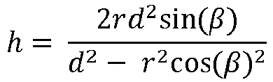
- b the ellipse's vertical parameter
- r the diameter of the circle (diameter of the bottleneck)
- d the distance from the view point to the border of the circle
- ⁇ ⁇ / 2- ⁇ ( ⁇ is the angle from the normal to the surface and the view point).
- a preferred embodiment is to apply a counter deformation that corrects critical distortions and provides a large range of readability.
- 2D barcode readers typically deal with a certain amount of perspective distortion, so the main focus is to minimize the effect of the elliptical distortion such that the scanned 2D barcode approaches a 2D barcode that has gone through a perspective transformation.
- a first transformation is applied to the generated 2D barcodes and deals with the horizontal compression effect caused by the rounded support.
- This transformation is basically a non-linear stretching of the code on the horizontal axis and will make the code appear straight when viewed from the 0° angle. In the described examples of specific bottles and given 2D barcode size, the stretching is minimal and represents a 3-4 % total stretch (i.e. width becomes 4% larger than height).
- a first calculation is made to determine the parameters of the ellipse that appears when looking at the circle at the 2D barcode's center from a certain angle and distance. This ellipse is then used to determine the inverse vertical displacement that will produce straight lines for the given input view point.
- FIG. 6 an algorithm describing how to generate a pre-compensated 2D barcode according to an embodiment of the invention is illustrated.
- the exemplary algorithm executed by a processor of a computing system has the following general steps:
- the parameters necessary for the generation of the 2D barcode matrix may be received from a memory of the computer system, or downloaded from a server, or input manually into the computing system, or any combination thereof.
- the bit matrix of the 2D barcode can be generated by a standard barcode generator algorithm per se known, using parameters which may include :
- the bit matrix may contain one bit per elementary cell and forms the base that is modified in the subsequent steps.
- This step performed by the algorithm involves calculating the horizontal cell sizes.
- the physical size of the barcode's elementary cells must take into account the wrapping around the surface. This means determining the actual wrapped sizes of the uniformly-sized perceived cells.
- the width of the projection of the perceived cell size on the cylinder is calculated and may be stored in an array in a memory of the computer system or used directly to expand the initial bit matrix.
- the inputs for this calculation may include:
- This step performed by the algorithm is to expand a bit matrix defining the horizontal and vertical positions (rows and columns) of elementary cells of the barcode, using the horizontal cell sizes obtained above.
- the bit matrix cells are scaled horizontally according to sizes that correspond their column position in the matrix. Cells at the horizontal ends (i.e. vertical outer edges of the barcode) will be larger than the cells in the middle of the barcode.
- Each cell is also scaled vertically, preferably by a fixed factor that is obtained by dividing the perceived vertical size of the 2D barcode by the number of rows of the initial bit matrix. The result produces an image that when applied to the surface and viewed from the normal (perpendicular) to the surface is perceived as square.
- steps S2 and S3 may be performed separately or may be performed at the same time.
- the parameters of the ellipse are calculated by the algorithm.
- a cylindrical section viewed at a certain angle and distance has the shape of an ellipse.
- the parameters of the ellipse are calculated taking into account values stored or entered in the computer system for the diameter of the surface, the viewing angle and the distance from the camera to the surface.
- the pixel displacements in the vertical direction (y-displacements) for the image based on the calculated ellipse may then be calculated for each horizontal pixel position (for each x-position).
- the vertical positions on the ellipse can be determined for all the positions on the horizontal axis in this step. These vertical positions may be used to compensate for the elliptical effect by shifting each of the extended 2D barcode columns obtained in step S2 by the vertical displacement corresponding to its horizontal position.
- These displacements may be pre-computed and kept in an array in a memory of the computer system or used directly to shift the extended 2D barcode.
- the image may then be distorted vertically according to the pixel y-displacements.
- the extended 2D barcode obtained in step S2 is distorted thanks to the vertical displacements obtained for all its columns positions. Each column is shifted vertically which produces 2D barcodes with a convex top and matching concave bottom.
- a 2D barcode image file may then be generated by the algorithm for printing or for generating a printing image based on the printing resolution parameter defined in step S1.
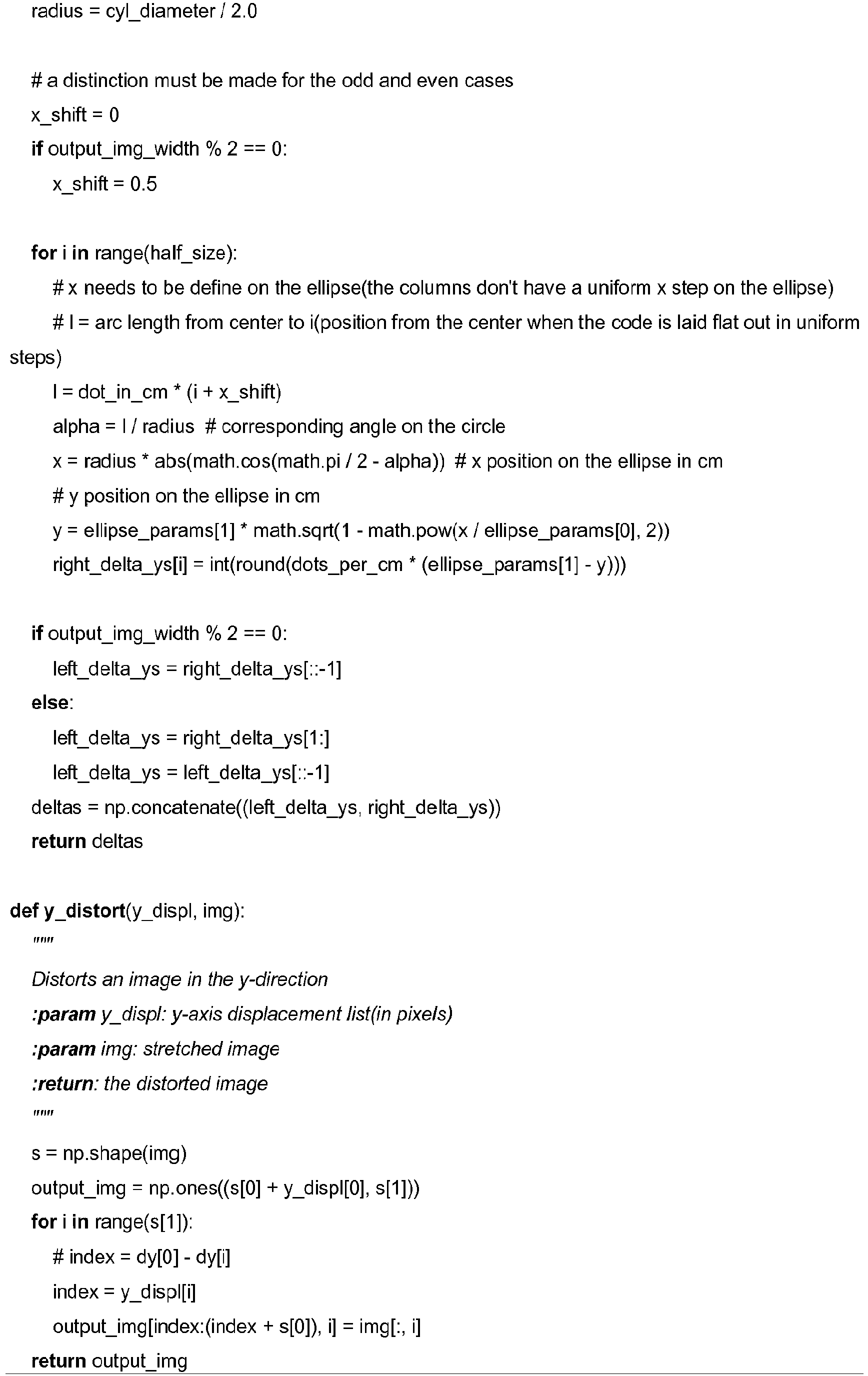
- This function calculates the cell sizes in pixels for a cylinder so that the perceived code is square. For each cell on the x-axis, it calculates the width of its projection on the cylinder, then stores the result in array, and finally, return the array of lengths.
- Stretching the image horizontally may be done with function:
- the stretching on the x-axis will be done according to the provided lengths and on the y-axis the cells will be scaled by the middle length value. For each cell on the x-axis, it expands the cells of the column vertically by the middle value of pixel_lengths, it expands the cells of the column horizontally by the value of pixel_lengths that corresponds to the columns position.
- the function returns the new expanded array
- This function calculates the parameters of the ellipse that appears when looking at a cut cylinder at a certain angle and distance.
- This function calculates the pixel y-displacements for the image according to the given ellipse.
- Distorting the image vertically may be done with the following function, which distorts the image in the y-direction.
- Min angle Max angle range normal code -15 15 30 pre-compensated - 0 -16 16 32 10 -9 25 34 20 -2 33 35 30 5 37 32 40 10 40 30 50 16 43 27 60 23 45 22
- Table showing, for a normal QR Code, and different pre-compensated QR Codes, the minimum reading angle and maximum reading angle.
- the i-nigma scanning application on iPhone was used for testing.
- pre-compensated codes may not only increase the reading range, but more importantly allow to increase the maximum reading angle. Even though it comes at the cost of a reduced minimal reading angle, for reasons explained above having a higher maximum reading angle is much more preferable from a user perspective. From the results, pre-compensated codes with input angles of 10 to 40 degrees appear to be particularly well suited for placement of 1.6cm QR Codes on standard wine bottles with parameters above. Of course, the optimal range will depend on the QR Code size, support diameter, and other support and viewing parameters.
- the phone brand also plays a role in the codes' readability.
- the cause being the different cameras' specifications: the number of sensors, the differences in the image compression, the field of view, the zoom factor, output size, etc.
- the number of sensors the differences in the image compression, the field of view, the zoom factor, output size, etc.
Description
- The present invention relates to a process of generating a 2D barcode (also commonly called a QR code).
- It is well known that 2D Barcode reading can be challenging, because of printing and scanning conditions. In some cases, printing and scanning may be done in overall good conditions, however the difficulty of reading a 2D barcode increases when the 2D barcode is applied on a non-planar surface, and the decoder cannot be optimized for such conditions.
- The four alignment patterns on QR Codes allow the codes to be decoded with a strong perspective angle. Indeed, the position of four reference points is sufficient to reconstruct the original image from potentially any perspective transform.
Figure 1 shows an example of a 2D barcode scan that is easily decoded with a standard QR Code scanning application on an Android phone. However, when the QR Code is placed on a non-planar surface, for example on a cylindrical surface with relatively small radius (if the radius is high, a perspective transform may be a good enough approximation for decoding), decoding generally become much less reliable. - Codes are increasingly applied near the top of wine or spirits bottles, which is in most cases a cylindrical surface of small radius. Indeed, such codes are often placed on tamper-evident labels, which protect the bottle against counterfeiting. As the label breaks during opening, it cannot be reused on a refilled bottle. Also, these codes are often used as part of marketing campaigns, and by being placed near the top of the bottle they are more easily noticed by the consumer, and therefore more likely to be scanned.
- Consumers need to be able to scan 2D barcodes with the software applications that they use on a daily basis installed on a portable electronic device, for instance on a smartphone. For instance, WeChat, a widely used messaging application in China, is equipped with a QR Code scanner, and a large proportion of 2D barcode scans in China is made through this application installed on the user's smartphone. However, such applications are not optimized to decode 2D barcodes on non-planar surfaces such as cylinders.
- In the prior art, various techniques have been developed to optimize the reading of codes. For example
US6814291 proposes a method of reading a two-dimensional barcode symbol that is susceptible to distortion, by using template matching techniques. A drawback with such technique is the need to modify the decoder, which limits the applications that can be used. - The application of anamorphosis to conform images to planar, cylindrical, conical, and parabolic surfaces is well developed. The degree of pre-distortion of an image that is necessary for such surfaces can be developed by applying known geometric principles. Even more advanced techniques, such as in
US7555157 , transform graphical images such that they are adapted to be applied to a three-dimensional topography of a substrate to which the image is to be applied. After the image is applied to the substrate, the image conforms to the topography of the substrate. While very powerful, such techniques are not adapted to the specificities of 2D barcode decoding. -
- Attempts to address the problem of reading barcodes on cylindrical surfaces can be found in
CN102682266 and inUS8292182 . InCN102682266 , a continuous image acquisition of a rotating barcode is proposed. InUS8292182 , the barcode rotates with the cylindrical element in the scanning area of a reader in order for the reader to completely read the barcode. These techniques are for reading barcodes on cylindrical surfaces during the manufacturing process, but these do not address the problem of reading barcodes on a cylindrical surface by a standard image scanner. - In
US4864112 a unidimensional barcode adapted for a cylindrical surface is disclosed. The technique adopted therein is not intended for a 2D barcode and moreover the reading direction is assumed to be in a plane essentially orthogonal to the barcode surface. Other barcode reading techniques relevant to reading barcodes on cylindrical surfaces are disclosed inJP 2009025992 A US 6556690 ,US5854478 ,WO2005067533 ,US7555157 . - In view of the aforegoing, it is an object of this invention to provide a 2D barcode that is more easily readable with standard portable image scanners, when the 2D barcode is placed on a non-planar surface such as a cylinder.
- It is advantageous to provide a 2D barcode that is adapted for placement and optimal scanning with standard or simple portable scanners on a cylindrical, conical or round neck of a bottle, such as a wine bottle.
- Objects of the invention have been achieved by providing a a method of generating an image of a two dimensional barcode for placement on a curved surface such as a portion of a neck of a bottle according to
claim 1. - The inventors have realized the one of the difficulties of decoding a 2D barcode placed near the top of a bottle with many scanners and applications stems from user behavior. Consumers and other users have a tendency to scan by placing their smartphone higher than the bottle, facing down at an angle with respect to the surface of the 2D barcode. And if the LED light of the smartphone is active, which is needed in low light environment, the specular reflection which arises may make scanning very difficult or impossible if the scan is made without an angle. The invention improves the reliability of scanning by optimizing the shape of the 2D barcode to take into account both the specificities of the non-planar surface, and the conditions in which the scanning takes place, in particular typical user behaviour.
- Disclosed herein is a two dimensional barcode for placement on a portion of a neck of a bottle, the barcode comprising a top edge, a bottom edge, a left edge (a right edge, and code elements arranged along horizontal lines extending between the left edge and the right edge. The horizontal lines of code elements and the top and bottom edges are curved such that the top edge has a convex shape and the bottom edge a concave shape, whereby the top edge is defined as the edge closest to the scanner or viewpoint. A top edge may therefore represent a lower edge if the 2D code bar is configured to be read from below rather than above the code bar. The meaning of the terms "top", "bottom", and "horizontal" in relation to the 2D barcode of the present description is thus intended to be relative to the intended scan viewing/reading position and not an actual absolute position or direction.
- In an example, the curve of the lines of code elements and the top and bottom edges is shaped substantially as a portion of an ellipse.
- In an example, the bottom edge is longer than the top edge.
- In an example, the degree of curvature of the lines of code elements and the top and bottom edges is configured for a diameter of the portion of the neck of the bottle, a greater curvature being provided for a smaller diameter.
- In an example, the 2D barcode comprises a support on which the code elements are printed. The support may comprise an adhesive layer on a side of the support opposite a side on which the code elements are printed. The support may be made of or comprise paper or a flexible polymer layer.
- In an example, each of the top, bottom, right and left edges have a length inferior to 26mm.
- In an example, the two dimensional barcode comprises a global deformation described by the following formula:
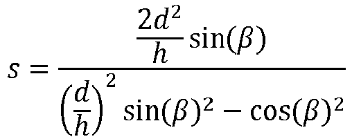
- s is the 2D barcode's physical printed height, h is the perceived height of the 2D barcode, d is the distance from a pre-defined scanner view point, and
- β = π/2-α, where α is the angle between a normal N to the surface of the 2D barcode and said pre-defined scanner view point.
- The perceived height h of the 2D barcode 2D may be determined according to the following formula:
- Also disclosed herein is a bottle comprising a two dimensional barcode as set forth herein, wherein the two dimensional barcode is bonded on a portion of the neck of the bottle.
- In an example, the portion of the neck of the bottle is substantially cylindrical.
- In an example, the portion of the neck of the bottle is substantially conical.
- In an example, the portion of the neck of the bottle is substantially conically and concavely curved.
- In an example, the two dimensional barcode is placed on a base portion of the neck of the bottle distal from a pouring end of the neck of the bottle.
- Also disclosed herein is a method of generating an image of a two dimensional barcode for placement on a curved surface such as a portion of a neck of a bottle comprising the following steps executed by an algorithm in a computing system:
- (S1) - receiving from a memory in the computing system or from an external computing system or from manual input of data into the computing system, or any combination thereof, dimensional parameters of a two dimensional barcode prior to deformation and an input image of said two dimensional barcode prior to deformation,
- (S2)- calculating elementary cell sizes of the code elements so that the code element is visually perceived as a square when viewed from the predefined viewing angle taking into account the diameter of the curved surface
- (S3) - stretching, by means of an algorithm, the input image horizontally by scaling horizontally cells of a bit matrix of the 2D barcode according to sizes that correspond to column positions of said cells in the bit matrix, whereby cells at horizontal ends of the barcode are larger than the cells in the middle of the barcode,
- (S4) - calculating ellipse deformation parameters that correspond to the intersection of a plane at the viewing angle with curved surface,
- (S5) - calculating vertical displacements of pixels of the image based on the calculated ellipse deformation parameters,
- (S6) - distorting the stretched input image based on the ellipse deformation parameters and the vertical displacement,
- (S7) - outputting the image of said two dimensional barcode for generating a printing file.
- In step S3 each cell may also be scaled vertically, preferably by a fixed factor obtained by dividing the perceived vertical size of the 2D barcode by the number of rows of an initial bit matrix defining the rows and column of the code elements.
- Further objects and advantageous features of the invention will be apparent from the claims, from the detailed description, and annexed drawings, in which:
-
Figure 1 is an illustration of a conventional 2D barcode; -
Figure 2a is a schematic illustration of a measurement setup to test a 2D barcode on a bottle according to an example; -
Figure 2b is a side view of a portion of a bottle with a 2D barcode according to an example; -
Figure 2c is an illustration of a user taking a scan of a 2D barcode according to an example with a portable smartphone; -
Figure 3 is an illustration of a conventional 2D barcode on a neck of a bottle from a typical user viewing angle; -
Figures 4a and4b are illustration of a 2D barcode according to an example on a neck of a bottle from a zero viewing angle (fig. 4a ) and a typical user viewing angle (fig. 4b ); -
Figures 5a-5d are illustrations of a 2D barcode according to examples with different degrees of elliptical deformation for viewing angles of 10° (fig. 5a ), 20° (fig. 5b ), 30° (fig. 5c ), 40° (fig. 5d ); -
Figure 6 is a flow diagram illustrating a method of generating a 2D barcode according to an embodiment of the invention; -
Figure 7 is a graph illustrating a relationship between an elliptical deformation and a viewing angle, where the half parameter of the ellipse depends on the formula: -
Figures 8a and 8b are graphs illustrating a magnitude of distortion involved either when viewing a 2D barcode with a fixed printed size from different angles (the perceived size changes, diamond shaped points) or needed to obtain a code with a fixed perceived size at different angles (the physical size changes, triangular points). - Referring to the
figures 4a-5d , an example is schematically illustrated. For 2D barcodes placed on cylindrical, conical or curved bottle necks, common 2D barcode sizes typically range from 25mm x 25mm to 10mm x 10mm, for instance 16mm x 16mm. - The reading of standard 2D barcodes 4' (illustrated in
figures 1 and3 ) applied on the neck of abottle 1 is affected by two different kinds of deformations: physical distortions to the label/paper caused by curvatures in the bottleneck and perspective transformation caused by the viewing angle. These two factors explain why reading normal 2D barcodes on circular or cone-shaped surfaces creates additional challenges. A generic correction deformation method can allow the reading of 2D barcodes at higher angles, though this comes with a compromise on the lower angles. As will be seen in relation to the examples presented herein, different known scan image readers show similar results, which demonstrates the coherent and generic aspect of the 2D barcode. In particular the 2D barcode increases significantly the ease of use of various commonly available consumer scanning software applications. - Referring to
figures 2b to 4b , a printed2D barcode 4 is positioned on a portion of aneck 3 of abottle 1. The 2D barcode is printed on a label that is bonded with an adhesive to thesurface 5 of the neck. The label may be made essentially of paper, polymer or other flexible printable materials provided with an adhesive layer to bond to the bottle surface. Within the scope of the invention, the 2D barcode may also be printed or engraved directly on thesurface 5 of the bottle. The bottle may be made of glass, ceramic, polymer, or various other materials used for producing recipients, in particular bottles for containing liquids for human consumption. The invention is particularly well suited for 2D barcode labels bonded to the neck portions of wine and liquor bottles. Theneck 3 of thebottle 1 may have various shapes, ranging from cylindrical to conical to essentially conical with a convex or concave curved portion. - It is advantageous to place the 2D barcode on the neck of the bottle to improve visibility to a consumer and access for scanning. In some instances manufacturers prefer to place the 2D barcode at the
base 7 of the neck or on a curved or conical portion of the neck that is on average inclined slightly upwardly, in particular where the normal N (i.e. perpendicular) to thesurface 5 is at an angle greater than zero, for instance in the range of 10° to 35° with respect to the horizontal plane H. User's may obtain information on the product and access promotional material issued by the manufacturer or seller of the product. The 2D barcode may also serve to verify authenticity of the product. - QR codes are a frequently used type of 2D barcode and usually comprises positioning marks 6 at corners of the barcode that form reference points that serve to orient the reading of the barcode. A 2D barcode comprises
code elements 8 in the form of black and white essentially square or rectangular elements that are per se well known and need not be further described. Conventional 2D barcodes as illustrated infigure 1 may have an overall square orrectangular boundary 10 formed by atop edge 10a', abottom edge 10b', aleft side edge 10c', and aright side edge 10d'. Thecode elements 8 are arranged along horizontal code lines and vertical code lines, whereby the sequence of black and white elements along a code line represent a portion of the code to be read. - A user may scan the 2D barcode with a
portable scanning device 11, typically the user'ssmartphone 11, whereby users usually scan a 2D barcode on a bottle neck from a position above the 2D barcode and incline their camera down towards the 2D barcode as best illustrated infigure 2c . This leads most users to position the camera's centre axis C at a viewing angle α relative to the normal N of the bottle neck surface that is non-zero, typically in a range of 10° to 40°. - In order to improve the readability of the scanned 2D barcode, the horizontal code lines of the 2D barcode are deformed such that the
top edge 10a andbottom edge 10b are curved upwards, namely the top edge has a convex shape and the bottom edge has a concave shape when seen from a position above thetop edge 10a. The curved horizontal code lines extending between the left and right side edges 10c, 10d compensate for some or all of the deformation, from the perspective of a non-zero viewing angle α relative to the normal N of the surface of the 2D barcode, and taking into account the curvature of the bottle neck. -
Figure 3 illustrates a view of a conventional 2D barcode from the perspective of a non-zero viewing angle α relative to the normal N of the surface of the 2D barcode, whereby the top andbottom edges 10a', 10b' are seen as curved due to the curvature of the bottle neck. -
Figure 4a illustrates a view of a 2D barcode according to an example from the perspective directly normal N to the surface of the 2D barcode, whereby the top andbottom edges figure 4b , the curvature of the top and bottom edges appear less curved and at a specific angle appear straight. The reduced curvature at the typical scanning angle improves the readability of the scanned 2d barcode. - The curvature of the horizontal code lines of the 2D barcode may be varied according to the curvature of the neck of the bottle on which it is intended to be bonded, namely to the diameter of the neck of the bottle.
- In an example (not shown), the curvature of horizontal code lines may vary between the
top edge 10a andbottom edge 10b such that the curvature of thetop edge 10a is different to the curvature of thebottom edge 10b, for placement on a non-cylindrical bottle neck portion, for instance conical, concave or convex bottle neck portion, to take into account the different diameters at the positions of the 2D barcode between the top and bottom edges. The curvatures of the top edge and curvature of the bottom edge may thus be configured to generate the same degree of reduction of the curvature at a pre-defined non-zero viewing angle α taking into account a varying diameter of bottle neck between the top and bottom edges. - In an example (not shown), the length of the
top edge 10a may be shorter than the length of thebottom edge 10b for placement on a conical or generally conical (concavely or convexly curved) bottle neck portion, to take into account the different diameters at the positions of the 2D barcode at the top and bottom edges. The lengths of the top edge and of the bottom edge may thus be configured to reduce the deviation angle of the side edges 10c, 10d from parallelism, at a pre-defined non-zero viewing angle α, taking into account the greater diameter of bottle neck at the bottom edge compared to the top edge. - An advantage of a non-perpendicular camera viewing angle is the avoidance of reflection from the scanned surface. In effect, encouraging a user to scan a 2D barcode with the camera axis aligned with the Normal N of the surface may lead to difficulties in reading the code due to reflection from the scanned surface. By encouraging the user to scan with the camera axis at a non-zero angle with respect to the Normal N, undesirable reflection from the scanned area is avoided.
- When placed on a flat surface, scanning apps can in general detect 2D barcodes scanned up to 60° from the normal. But when placed on a cylindrical or cone-shaped surface, the 2D barcodes are affected by different kinds of deformations: surface based and perspective distortions.
- The first source is the physical distortion of the surface. A picture taken of a normal 2D barcode, from the normal to the surface at the 2D barcode's center, will not have the same width and height proportion. This effect is due to the curvature of the portion of the bottle on which the 2D barcode is placed and depends on the diameter of that portion as well as the size of the code. The closer the 2D barcode size is to the bottle portion diameter, the greater the distortion will be. When viewed from different vertical angles, this wrapping around the bottleneck produces essentially elliptical deformations of the printed straight code lines. These non-projective transformations are one of the main causes for the non-detectability of the 2D barcodes. Indeed, the 2D barcode's detection method is based upon finding specific black and white sequences along straight code lines.
- Moreover, on a cone, the curvature of the support depends on the position on the vertical axis. Therefore, the elliptical distortions of the codes will also depend on the position on the vertical axis. On a cylinder, a normal 2D barcode will globally have symmetrical reading-angle limits, for instance if the maximum reading angle is 15°(from the surface normal) then its minimum reading angle will be - 15°. This is because the elliptical deformations will be symmetrical. However, on a cone this doesn't apply anymore because of the curvature difference. The minimum reading angle will be greater than the maximum reading angle, because the deformation will be smaller at the base of the cone (smaller curvature). This effect is clearly visible, for example, a 1.6x1.6cm QR code applied to a first test bottle reads on average from -22° to 18°. Correcting for an elliptical deformation will affect the symmetry of the physical printed code, and affect the symmetry and size of the reading range.
- The second type of distortion comes from the perspective transformation caused by the viewing angle (assuming the code is scanned from the front, thus with no lateral angle). Perspective distortions of the horizontal code lines on cylindrical or conical support surfaces result in essentially elliptical distortions. Compensating for it implies adding a fair amount of distortion to the pre-printing code. Because the deformations depend on the viewing angle, compensation will work well for a given angle range but add distortions for angles outside of the angle range and therefore reduces the range of the 2D barcode readable angles.
- To better understand what is implied, consider the following. From a perspective point of view, looking at the center of a 2D barcode from a different angle generates a global y-axis deformation (of the entire 2D barcode) described by the following formula:

- In order to create a 2D barcode with a fixed perceived size for a certain angle to better manage the distortion, a global deformation described by the following formula may be applied:

- Let us assume the 2D barcode is either a version 1 (21x21) or a version 2 (25x25) with error level Q (or M) using the alphanumeric data set (45 characters). We shall further consider two different bottles where the necks have a substantially cone-shaped portion on which the 2D barcode will be applied.
- The first bottle tested has a 1.6cm vertical section ranging from 4.14cm diameter to 3.57cm diameter. This produces a cone with a base diameter of 4.14cm and a height of 11.56cm, which is described by the following formula:

- The first test bottle's cone section is defined by a base radius of r = 2.135cm and a height of h = 8.87cm, thus it has a 13.53° angle with the floor.
- A subset of the distorted codes (corresponding to different viewing angles) were printed and stuck onto a standard or commonly available bottle of wine. Using one of the most efficient QR readers presently on the market (i-nigma), a series of scans were taken to determine the readable angle range for those codes and thus reduce the search range for the other readers. The measurements were made on a vertical arc of a circle of radius r = 10cm around the codes' center. The reading limits were then determined by increasing/decreasing the angle. The limits for the other readers were then determined by conducting a search around the previously found limits.
- The two graphs of
figures 8a and 8b compare the magnitude of distortion involved either when viewing a code with a fixed printed size from different angles (the perceived size changes, diamond points) or needed to obtain a code with a fixed perceived size at different angles (the physical size changes, triangular points). (Note: there is a vertical asymptote at 85.42° due to the particular settings.) We see that the distortion needed to maintain a perceived height is similar to the distortion of a fixed height for small angles, but becomes much larger for bigger angles. The impact of the angle on the elliptical distortion also grows as the angle increases as illustrated inFigure 7 . The half parameter of the ellipse depends on this formula:
- From the tests to correct fully the vertical compression, fully correcting the deformations in order to produce a perfectly square 2D barcode for a given angle is not the preferred approach. As explained earlier, the more specific the counter deformation, the lower the reading range will be because of the added distortions to the other angles. Hence, a preferred embodiment is to apply a counter deformation that corrects critical distortions and provides a large range of readability. 2D barcode readers typically deal with a certain amount of perspective distortion, so the main focus is to minimize the effect of the elliptical distortion such that the scanned 2D barcode approaches a 2D barcode that has gone through a perspective transformation.
- A first transformation is applied to the generated 2D barcodes and deals with the horizontal compression effect caused by the rounded support. This transformation is basically a non-linear stretching of the code on the horizontal axis and will make the code appear straight when viewed from the 0° angle. In the described examples of specific bottles and given 2D barcode size, the stretching is minimal and represents a 3-4 % total stretch (i.e. width becomes 4% larger than height).
- Then in order to deal with the elliptical distortion, a first calculation is made to determine the parameters of the ellipse that appears when looking at the circle at the 2D barcode's center from a certain angle and distance. This ellipse is then used to determine the inverse vertical displacement that will produce straight lines for the given input view point.
- Referring to
figure 6 , an algorithm describing how to generate a pre-compensated 2D barcode according to an embodiment of the invention is illustrated. The exemplary algorithm executed by a processor of a computing system has the following general steps: - The parameters necessary for the generation of the 2D barcode matrix may be received from a memory of the computer system, or downloaded from a server, or input manually into the computing system, or any combination thereof.
- These parameters may include :
- The dimensions of the surface on which the 2D barcode in intended to be positioned, for instance the diameter of a bottle neck,
- The dimensions and specifications of the 2D barcode (for instance width and height; size of the elementary cells of the code elements, number of elementary cells per horizontal line and per vertical line)
- a printing resolution (for instance the dots per inch dpi)
- a pre-defined scan viewing angle relative to the normal to the surface of the 2D barcode
- a pre-defined perceived 2D barcode image width, namely the width the 2D barcode should visually have when applied to the curved surface
- the distance from the camera to the 2D barcode
- The bit matrix of the 2D barcode can be generated by a standard barcode generator algorithm per se known, using parameters which may include :
- the content of the barcode
- the version of the barcode(which also defines its size in terms of elementry cells)
- the error correction level
- The bit matrix may contain one bit per elementary cell and forms the base that is modified in the subsequent steps.
- This step performed by the algorithm involves calculating the horizontal cell sizes. In order to obtain a code element that is visually perceived as a square when applied to a curved surface and viewed from the normal to the surface, the physical size of the barcode's elementary cells must take into account the wrapping around the surface. This means determining the actual wrapped sizes of the uniformly-sized perceived cells. For each column of the 2D barcode's bit matrix, the width of the projection of the perceived cell size on the cylinder is calculated and may be stored in an array in a memory of the computer system or used directly to expand the initial bit matrix.
- The inputs for this calculation may include:
- the dimensions of the 2D barcode in terms of elementary cells.
- the desired perceived size of the barcode
- the dimensions of the surface, for instance the diameter of the bottleneck
- the printing resolution
- This step performed by the algorithm is to expand a bit matrix defining the horizontal and vertical positions (rows and columns) of elementary cells of the barcode, using the horizontal cell sizes obtained above. The bit matrix cells are scaled horizontally according to sizes that correspond their column position in the matrix. Cells at the horizontal ends (i.e. vertical outer edges of the barcode) will be larger than the cells in the middle of the barcode. Each cell is also scaled vertically, preferably by a fixed factor that is obtained by dividing the perceived vertical size of the 2D barcode by the number of rows of the initial bit matrix. The result produces an image that when applied to the surface and viewed from the normal (perpendicular) to the surface is perceived as square.
- The above described steps S2 and S3 may be performed separately or may be performed at the same time.
- The parameters of the ellipse (width and height of the ellipse axes) that correspond to the intersection of a plane at the viewing angle with the cylindrical surface of the curved surface (e.g. bottle neck) are calculated by the algorithm. A cylindrical section viewed at a certain angle and distance has the shape of an ellipse. In this process step carried out by the algorithm, the parameters of the ellipse (half-height and half-width of the axes) are calculated taking into account values stored or entered in the computer system for the diameter of the surface, the viewing angle and the distance from the camera to the surface.
- The pixel displacements in the vertical direction (y-displacements) for the image based on the calculated ellipse may then be calculated for each horizontal pixel position (for each x-position). Given the perceived ellipse's parameters, the vertical positions on the ellipse can be determined for all the positions on the horizontal axis in this step. These vertical positions may be used to compensate for the elliptical effect by shifting each of the extended 2D barcode columns obtained in step S2 by the vertical displacement corresponding to its horizontal position. These displacements may be pre-computed and kept in an array in a memory of the computer system or used directly to shift the extended 2D barcode.
- The image may then be distorted vertically according to the pixel y-displacements.
- In this process step performed by the algorithm, the extended 2D barcode obtained in step S2 is distorted thanks to the vertical displacements obtained for all its columns positions. Each column is shifted vertically which produces 2D barcodes with a convex top and matching concave bottom.
- A 2D barcode image file may then be generated by the algorithm for printing or for generating a printing image based on the printing resolution parameter defined in step S1.
- These steps are described in more detail herebelow by presenting the algorithm in pseudo-code. In the appendix the detailed algorihms are given for exemplary purposes, in the python programming language.
-
- cell_widths = get_cell_widths_in_pixels_horizontal_stretch(...)
- im_stretched = stretch_qr_horizontally(..., cell_widths)
- ellipse_params = calculate_ellipse_params_center(...)
- displacements = calculate_dy_displacements(ellipse_params,...)
- distorted_im = y_distort(displacements, im_stretched)
- Let us now review the main functions.
- Calculating cell sizes is done with function:_
- get cell widths in pixels horizontal stretch(qr_size, output_img_width, cylinder_diameter, resolution):
- :param qr_size: number of cells of the QR on one axis (e.g. 33)
- :param output_perceived_img_width: the width the code should visually have when applied to the cylinder
- :param cylinder_diameter: the cylinder diameter (cm)
- :param resolution: the printing resolution (dpi)
- return: a list of cell sizes which length matches the number of cells in the QR
- This function calculates the cell sizes in pixels for a cylinder so that the perceived code is square. For each cell on the x-axis, it calculates the width of its projection on the cylinder, then stores the result in array, and finally, return the array of lengths.
- Stretching the image horizontally may be done with function:
- stretch qr_horizontally(qr_size, qr_matrix, pixel_lengths):
- :param qr_size: number of cells of the QR on one axis (e.g. 33)
- :param qr_matrix: binary matrix of size qr_size
- :param pixel_lengths: a list of the cell sizes(in pixels) of same length as the QR width
- :return: an array that represents the stretched code
- The stretching on the x-axis will be done according to the provided lengths and on the y-axis the cells will be scaled by the middle length value. For each cell on the x-axis, it expands the cells of the column vertically by the middle value of pixel_lengths, it expands the cells of the column horizontally by the value of pixel_lengths that corresponds to the columns position. The function returns the new expanded array
- Calculating the ellipse parameters may be done with function:
- calculate ellipse params center(cylinder_diameter, capture_angle, distance):
- :param cyl_diameter: the cylinder diameter (cm)
- :param capture_angle: the angle at the normal of the camera and the QR (Radians)
- :param distance: distance between the code and the camera along the normal (cm)
- :return: the a and b ellipse's parameters (for: (x/a)^2 + (y/b)^2 = 1)
- This function calculates the parameters of the ellipse that appears when looking at a cut cylinder at a certain angle and distance.
- Calculating the vertical displacements may be done with function:
- calculate dy_displacements(ellipse_params, output_img_width, resolution, cyl_diameter):
- :param cyl_diameter: the cylinder diameter (cm)
- :param ellipse_params: the ellipse's parameters(a,b)
- :param output_img_width: the image's width
- :param resolution: the printing resolution (dpi)
- return: a list of y-axis displacements for all the columns of the image to match the ellipse's distortion
- This function calculates the pixel y-displacements for the image according to the given ellipse.
- Distorting the image vertically may be done with the following function, which distorts the image in the y-direction.
- y distort(y_displacements, img):
- :param y_displacements: y-axis displacement list(in pixels)
- :param img: stretched image
- return: the distorted image
-
Min angle Max angle range normal code -15 15 30 pre-compensated - 0 -16 16 32 10 -9 25 34 20 -2 33 35 30 5 37 32 40 10 40 30 50 16 43 27 60 23 45 22 - Table showing, for a normal QR Code, and different pre-compensated QR Codes, the minimum reading angle and maximum reading angle. The i-nigma scanning application on iPhone was used for testing.
- perceived code size: 1.6 cm
- support diameter: 3.088cm
- print resolution: 600dpi
- distance QR center to camera: 10cm
- The results demonstrate that the pre-compensated codes may not only increase the reading range, but more importantly allow to increase the maximum reading angle. Even though it comes at the cost of a reduced minimal reading angle, for reasons explained above having a higher maximum reading angle is much more preferable from a user perspective. From the results, pre-compensated codes with input angles of 10 to 40 degrees appear to be particularly well suited for placement of 1.6cm QR Codes on standard wine bottles with parameters above. Of course, the optimal range will depend on the QR Code size, support diameter, and other support and viewing parameters.
- The phone brand (and model) also plays a role in the codes' readability. The cause being the different cameras' specifications: the number of sensors, the differences in the image compression, the field of view, the zoom factor, output size, etc. However, for a global solution, one can determine optimal parameters by focusing on the mean reading results.
- In further experiments, the results obtained with the conditions described above (i-nigma, iPhone) were compared with other reading conditions. The reading range varies depending both on the smartphone and the scanning software application that is used The reading ability of each scanning application depends on the algorithms that it uses to binarize, detect the alignment patterns and correct for the different deformations. Three scanning apps were tested: i-nigma, WeChat and Wochacha. Reliability and reproducibility of results are affected by slight variations that may be caused by: the precise camera positioning (angle-wise, distance-wise); the code positioning on the bottle, in particular the code may not have been stuck exactly at the right place and/or in a perfectly vertical position; the lighting conditions may differ from one test to the other; and possible variations and updates of the camera application version. However, it may be observed that this does not affect the choice of pre-compensated QR Codes, whereby for the above conditions pre-compensated codes with input angles 10 to 40 degrees function well.
-


Claims (2)
- Method of generating an image of a two dimensional barcode (4) for placement on a curved surface such as a portion of a neck (3) of a bottle (1), the two dimensional barcode comprising a top edge (10a), a bottom edge (10b), a left edge (10c) a right edge (10d), and code elements (8) arranged along horizontal lines extending between the left edge and the right edge, the horizontal lines of code elements and the top and bottom edges are curved such that the top edge has a convex shape and the bottom edge a concave shape, the method comprising the following steps executed by an algorithm in a computing system:(S1) - receiving from a memory in the computing system or from an external computing system or from manual input of data into the computing system, or any combination thereof, dimensional parameters of said two dimensional barcode prior to deformation and an input image of said two dimensional barcode prior to deformation,(S2)- calculating elementary cell sizes of the code elements so that the code element is visually perceived as a square when viewed from the predefined viewing angle in a vertical plane taking into account the diameter of the curved surface(S3) - stretching, by means of an algorithm, the input image horizontally by scaling horizontally cells of a bit matrix of the 2D barcode according to sizes that correspond to column positions of said cells in the bit matrix, whereby cells at horizontal ends of the 2D barcode are larger than the cells in the middle of the 2D barcode,(S4) - calculating ellipse deformation parameters that correspond to the intersection of a plane at the viewing angle with curved surface,(S5) - calculating vertical displacements of pixels of the image based on the calculated ellipse deformation parameters,(S6) - distorting the stretched input image based on the ellipse deformation parameters and the vertical displacement,(S7) - outputting the image of said two dimensional barcode (4) for generating a printing file.
- Method according to the preceding claim, wherein in step S3 each cell is also scaled vertically by a fixed factor obtained by dividing the perceived vertical size of the 2D barcode by the number of rows of the initial bit matrix.
Priority Applications (4)
| Application Number | Priority Date | Filing Date | Title |
|---|---|---|---|
| EP15171681.8A EP3104306B2 (en) | 2015-06-11 | 2015-06-11 | Two dimensional barcode |
| US15/735,026 US10133973B2 (en) | 2015-06-11 | 2016-06-03 | Two dimensional barcode |
| CN201680043815.5A CN107851203B (en) | 2015-06-11 | 2016-06-03 | Two-dimensional bar code |
| PCT/IB2016/053268 WO2016199004A1 (en) | 2015-06-11 | 2016-06-03 | Two dimensional barcode |
Applications Claiming Priority (1)
| Application Number | Priority Date | Filing Date | Title |
|---|---|---|---|
| EP15171681.8A EP3104306B2 (en) | 2015-06-11 | 2015-06-11 | Two dimensional barcode |
Publications (3)
| Publication Number | Publication Date |
|---|---|
| EP3104306A1 EP3104306A1 (en) | 2016-12-14 |
| EP3104306B1 EP3104306B1 (en) | 2021-02-17 |
| EP3104306B2 true EP3104306B2 (en) | 2023-11-01 |
Family
ID=53396324
Family Applications (1)
| Application Number | Title | Priority Date | Filing Date |
|---|---|---|---|
| EP15171681.8A Active EP3104306B2 (en) | 2015-06-11 | 2015-06-11 | Two dimensional barcode |
Country Status (4)
| Country | Link |
|---|---|
| US (1) | US10133973B2 (en) |
| EP (1) | EP3104306B2 (en) |
| CN (1) | CN107851203B (en) |
| WO (1) | WO2016199004A1 (en) |
Families Citing this family (16)
| Publication number | Priority date | Publication date | Assignee | Title |
|---|---|---|---|---|
| WO2013173728A1 (en) | 2012-05-17 | 2013-11-21 | The University Of North Carolina At Chapel Hill | Methods, systems, and computer readable media for unified scene acquisition and pose tracking in a wearable display |
| US11049476B2 (en) | 2014-11-04 | 2021-06-29 | The University Of North Carolina At Chapel Hill | Minimal-latency tracking and display for matching real and virtual worlds in head-worn displays |
| FR3044794B1 (en) * | 2015-12-03 | 2018-11-30 | Digital Packaging | PROCESS FOR PRODUCING AND CUSTOMIZING CONSUMER CONSUMER ITEMS FOR ACCESS TO CUSTOMIZED CONTENT |
| US10592536B2 (en) * | 2017-05-30 | 2020-03-17 | Hand Held Products, Inc. | Systems and methods for determining a location of a user when using an imaging device in an indoor facility |
| JP6434083B1 (en) * | 2017-05-31 | 2018-12-05 | 日本耐酸壜工業株式会社 | How to manage the reuse of returnable glass bottles |
| WO2019016815A1 (en) * | 2017-07-20 | 2019-01-24 | Hazan Nir | Multicolour rectangular photo markers and methods of using thereof |
| US10410372B1 (en) * | 2018-06-14 | 2019-09-10 | The University Of North Carolina At Chapel Hill | Methods, systems, and computer-readable media for utilizing radial distortion to estimate a pose configuration |
| CN109190735B (en) * | 2018-07-31 | 2021-10-15 | 华南农业大学 | Two-dimensional code generation method, system and device for cylindrical surface |
| JP7222593B2 (en) * | 2018-10-26 | 2023-02-15 | 大阪シーリング印刷株式会社 | Two-dimensional code |
| WO2020131077A1 (en) | 2018-12-20 | 2020-06-25 | Hewlett-Packard Development Company, L.P. | Read curved visual marks |
| FR3091612B1 (en) * | 2019-01-07 | 2021-01-29 | Konatic | method of associating a marking with an object |
| KR102085480B1 (en) * | 2019-06-14 | 2020-05-18 | 이광열 | Apparatus, system, method, and computer program for printing qr code |
| CN110502948B (en) * | 2019-07-05 | 2023-01-20 | 郭玮强 | Restoration method and device for folding two-dimensional code image and code scanning equipment |
| KR102085483B1 (en) * | 2019-07-05 | 2020-04-14 | 이광열 | System, method and program for distributing food |
| JP2021024206A (en) * | 2019-08-06 | 2021-02-22 | リンテック株式会社 | Transfer device and transfer method |
| DE102020106477A1 (en) | 2020-03-10 | 2021-09-16 | Versuchs- und Lehranstalt für Brauerei in Berlin (VLB) e.V. | Beverage bottle and system for identifying and delivering beverage bottles |
Citations (1)
| Publication number | Priority date | Publication date | Assignee | Title |
|---|---|---|---|---|
| FR2980609A1 (en) † | 2011-09-27 | 2013-03-29 | Bh Media | Object i.e. cup, has non-planar surface including representation of two-dimensional code, where representation includes projection that can be read in given direction of reading by system having reading device and decoding software |
Family Cites Families (19)
| Publication number | Priority date | Publication date | Assignee | Title |
|---|---|---|---|---|
| JPS63133282A (en) | 1986-11-26 | 1988-06-06 | Nippon Denso Co Ltd | Bar code label |
| JP3676443B2 (en) * | 1995-09-01 | 2005-07-27 | オリンパス株式会社 | Information reproducing apparatus and information reproducing method |
| US5854478A (en) | 1996-10-11 | 1998-12-29 | Intermec Ip Corp. | Method and apparatus for reading machine-readable symbols having surface or optical distortions |
| DE69830597D1 (en) * | 1997-04-08 | 2005-07-21 | Zih Corp | FORMATION FIXES, DOUBLE DATA CORRECTING, COLOR TRANSITION CODE, AND ITS PRODUCTION AND USE METHOD |
| US6341020B1 (en) | 1998-12-28 | 2002-01-22 | Xerox Corporation | Anamorphic object optimized function application for printer defect pre-compensation |
| US6005670A (en) | 1998-12-28 | 1999-12-21 | Xerox Corporation | Efficient identification of predicted printer defects for anamorphic pre-compensation |
| US6556690B1 (en) | 1999-06-17 | 2003-04-29 | Eastman Kodak Company | Articles bearing invisible encodements on curved surfaces |
| US7555157B2 (en) | 2001-09-07 | 2009-06-30 | Geoff Davidson | System and method for transforming graphical images |
| JP2005167454A (en) | 2003-12-01 | 2005-06-23 | Noritsu Koki Co Ltd | Image processor, image forming apparatus and image processing program |
| US6814291B1 (en) | 2003-12-15 | 2004-11-09 | Pitney Bowes Inc. | Robust barcode reader |
| JP2007520001A (en) * | 2004-01-14 | 2007-07-19 | インターナショナル バーコード コーポレイション | Scanable distortion compensation virtual barcode image |
| JP2009025992A (en) * | 2007-07-18 | 2009-02-05 | Isp:Kk | Two-dimensional code |
| US8542289B1 (en) * | 2008-02-08 | 2013-09-24 | Google Inc. | Mapping a two-dimensional image to a cylindrical surface using a tuned distortion curve |
| WO2010012249A1 (en) | 2008-07-31 | 2010-02-04 | Gerd Ecker | Label having a three-dimensional effect as a result of specific distortion upon detection by a camera |
| MY159805A (en) * | 2009-09-04 | 2017-02-15 | Yoshida Kenji | Information input/output device, information processing device, information input/output system, printed medium and information input/output method |
| TWI426455B (en) | 2011-03-04 | 2014-02-11 | Mas Automation Corp | Method and apparatus for reading bar code of battery pack element |
| CN102682266B (en) | 2012-05-17 | 2014-06-11 | 西北工业大学 | Cylindrical surface bidimensional bar code reading method based on image splicing |
| CN104057719A (en) * | 2013-03-23 | 2014-09-24 | 杨筑平 | Bar code printing method, device and system and bar code label |
| US20150028110A1 (en) * | 2013-07-29 | 2015-01-29 | Owens-Brockway Glass Container Inc. | Container with a Data Matrix Disposed Thereon |
-
2015
- 2015-06-11 EP EP15171681.8A patent/EP3104306B2/en active Active
-
2016
- 2016-06-03 CN CN201680043815.5A patent/CN107851203B/en active Active
- 2016-06-03 US US15/735,026 patent/US10133973B2/en active Active
- 2016-06-03 WO PCT/IB2016/053268 patent/WO2016199004A1/en active Application Filing
Patent Citations (1)
| Publication number | Priority date | Publication date | Assignee | Title |
|---|---|---|---|---|
| FR2980609A1 (en) † | 2011-09-27 | 2013-03-29 | Bh Media | Object i.e. cup, has non-planar surface including representation of two-dimensional code, where representation includes projection that can be read in given direction of reading by system having reading device and decoding software |
Also Published As
| Publication number | Publication date |
|---|---|
| EP3104306A1 (en) | 2016-12-14 |
| US10133973B2 (en) | 2018-11-20 |
| CN107851203B (en) | 2021-02-12 |
| CN107851203A (en) | 2018-03-27 |
| US20180157946A1 (en) | 2018-06-07 |
| EP3104306B1 (en) | 2021-02-17 |
| WO2016199004A1 (en) | 2016-12-15 |
Similar Documents
| Publication | Publication Date | Title |
|---|---|---|
| EP3104306B2 (en) | Two dimensional barcode | |
| US11270404B2 (en) | Digital watermarking applications | |
| US7380717B2 (en) | System and method for compensating for bar code image distortions | |
| CN105046184A (en) | Distortion image correction based two-dimensional code decoding method and system | |
| RU2568308C2 (en) | Streaming dot pattern, method of forming streaming dot pattern, method for information input/output using streaming dot pattern and dot pattern | |
| CN102799850B (en) | A kind of barcode recognition method and device | |
| US20170293992A1 (en) | Image code for processing information and device and method for generating and parsing same | |
| CN105046183A (en) | Decoding method and system for distorted QR (Quick Response) code | |
| US9959475B2 (en) | Table data recovering in case of image distortion | |
| JP2009540468A (en) | Multidimensional symbology and related methods | |
| CN113435556A (en) | Code generation and decoding method and anti-counterfeiting method of dot matrix code | |
| JP2011109637A (en) | Method for detecting alteration in printed document using image comparison analysis | |
| US20150302236A1 (en) | Method and device for identifying a two-dimensional barcode | |
| US9104936B2 (en) | Machine reading of printed data | |
| CA2744698A1 (en) | Image processing for curvature correction | |
| CN114239780A (en) | Anti-counterfeiting tracing code generation and verification method based on dot matrix | |
| BR112013011943B1 (en) | method for identifying a two-dimensional bar code in digital image data of the bar code, non-transitory computer readable medium and apparatus configured to identify a two-dimensional bar code in digital image data of the bar code | |
| US10083384B2 (en) | Display device for displaying barcode | |
| US20030190056A1 (en) | System and method for encoding and decoding data and position information using angular symbology and beacons | |
| US20030026448A1 (en) | Data encoding and decoding using angular symbology | |
| CN105046256B (en) | QR codes coding/decoding method based on distorted image correction and system | |
| CN112036420A (en) | Method for generating electronic price list, computing device and computer readable storage medium | |
| EP2790125B1 (en) | Method and apparatus for decoding a non-planar barcode | |
| CN113297872B (en) | Dotcode identification method and device | |
| NZ744514A (en) | System and method for placing scannable QR codes on small diameter cylindrical surfaces |
Legal Events
| Date | Code | Title | Description |
|---|---|---|---|
| PUAI | Public reference made under article 153(3) epc to a published international application that has entered the european phase |
Free format text: ORIGINAL CODE: 0009012 |
|
| STAA | Information on the status of an ep patent application or granted ep patent |
Free format text: STATUS: THE APPLICATION HAS BEEN PUBLISHED |
|
| AK | Designated contracting states |
Kind code of ref document: A1 Designated state(s): AL AT BE BG CH CY CZ DE DK EE ES FI FR GB GR HR HU IE IS IT LI LT LU LV MC MK MT NL NO PL PT RO RS SE SI SK SM TR |
|
| AX | Request for extension of the european patent |
Extension state: BA ME |
|
| STAA | Information on the status of an ep patent application or granted ep patent |
Free format text: STATUS: REQUEST FOR EXAMINATION WAS MADE |
|
| 17P | Request for examination filed |
Effective date: 20170614 |
|
| RBV | Designated contracting states (corrected) |
Designated state(s): AL AT BE BG CH CY CZ DE DK EE ES FI FR GB GR HR HU IE IS IT LI LT LU LV MC MK MT NL NO PL PT RO RS SE SI SK SM TR |
|
| TPAC | Observations filed by third parties |
Free format text: ORIGINAL CODE: EPIDOSNTIPA |
|
| GRAP | Despatch of communication of intention to grant a patent |
Free format text: ORIGINAL CODE: EPIDOSNIGR1 |
|
| STAA | Information on the status of an ep patent application or granted ep patent |
Free format text: STATUS: GRANT OF PATENT IS INTENDED |
|
| INTG | Intention to grant announced |
Effective date: 20201006 |
|
| RIN1 | Information on inventor provided before grant (corrected) |
Inventor name: LANDRY, PAUL Inventor name: PICARD, JUSTIN |
|
| GRAS | Grant fee paid |
Free format text: ORIGINAL CODE: EPIDOSNIGR3 |
|
| GRAA | (expected) grant |
Free format text: ORIGINAL CODE: 0009210 |
|
| STAA | Information on the status of an ep patent application or granted ep patent |
Free format text: STATUS: THE PATENT HAS BEEN GRANTED |
|
| AK | Designated contracting states |
Kind code of ref document: B1 Designated state(s): AL AT BE BG CH CY CZ DE DK EE ES FI FR GB GR HR HU IE IS IT LI LT LU LV MC MK MT NL NO PL PT RO RS SE SI SK SM TR |
|
| REG | Reference to a national code |
Ref country code: GB Ref legal event code: FG4D |
|
| REG | Reference to a national code |
Ref country code: CH Ref legal event code: EP |
|
| REG | Reference to a national code |
Ref country code: DE Ref legal event code: R096 Ref document number: 602015065494 Country of ref document: DE |
|
| REG | Reference to a national code |
Ref country code: AT Ref legal event code: REF Ref document number: 1362442 Country of ref document: AT Kind code of ref document: T Effective date: 20210315 Ref country code: CH Ref legal event code: NV Representative=s name: REUTELER AND CIE S.A., CH |
|
| REG | Reference to a national code |
Ref country code: IE Ref legal event code: FG4D |
|
| REG | Reference to a national code |
Ref country code: LT Ref legal event code: MG9D |
|
| REG | Reference to a national code |
Ref country code: NL Ref legal event code: MP Effective date: 20210217 |
|
| PG25 | Lapsed in a contracting state [announced via postgrant information from national office to epo] |
Ref country code: PT Free format text: LAPSE BECAUSE OF FAILURE TO SUBMIT A TRANSLATION OF THE DESCRIPTION OR TO PAY THE FEE WITHIN THE PRESCRIBED TIME-LIMIT Effective date: 20210617 Ref country code: LT Free format text: LAPSE BECAUSE OF FAILURE TO SUBMIT A TRANSLATION OF THE DESCRIPTION OR TO PAY THE FEE WITHIN THE PRESCRIBED TIME-LIMIT Effective date: 20210217 Ref country code: FI Free format text: LAPSE BECAUSE OF FAILURE TO SUBMIT A TRANSLATION OF THE DESCRIPTION OR TO PAY THE FEE WITHIN THE PRESCRIBED TIME-LIMIT Effective date: 20210217 Ref country code: GR Free format text: LAPSE BECAUSE OF FAILURE TO SUBMIT A TRANSLATION OF THE DESCRIPTION OR TO PAY THE FEE WITHIN THE PRESCRIBED TIME-LIMIT Effective date: 20210518 Ref country code: HR Free format text: LAPSE BECAUSE OF FAILURE TO SUBMIT A TRANSLATION OF THE DESCRIPTION OR TO PAY THE FEE WITHIN THE PRESCRIBED TIME-LIMIT Effective date: 20210217 Ref country code: BG Free format text: LAPSE BECAUSE OF FAILURE TO SUBMIT A TRANSLATION OF THE DESCRIPTION OR TO PAY THE FEE WITHIN THE PRESCRIBED TIME-LIMIT Effective date: 20210517 Ref country code: NO Free format text: LAPSE BECAUSE OF FAILURE TO SUBMIT A TRANSLATION OF THE DESCRIPTION OR TO PAY THE FEE WITHIN THE PRESCRIBED TIME-LIMIT Effective date: 20210517 |
|
| REG | Reference to a national code |
Ref country code: AT Ref legal event code: MK05 Ref document number: 1362442 Country of ref document: AT Kind code of ref document: T Effective date: 20210217 |
|
| PG25 | Lapsed in a contracting state [announced via postgrant information from national office to epo] |
Ref country code: SE Free format text: LAPSE BECAUSE OF FAILURE TO SUBMIT A TRANSLATION OF THE DESCRIPTION OR TO PAY THE FEE WITHIN THE PRESCRIBED TIME-LIMIT Effective date: 20210217 Ref country code: RS Free format text: LAPSE BECAUSE OF FAILURE TO SUBMIT A TRANSLATION OF THE DESCRIPTION OR TO PAY THE FEE WITHIN THE PRESCRIBED TIME-LIMIT Effective date: 20210217 Ref country code: LV Free format text: LAPSE BECAUSE OF FAILURE TO SUBMIT A TRANSLATION OF THE DESCRIPTION OR TO PAY THE FEE WITHIN THE PRESCRIBED TIME-LIMIT Effective date: 20210217 Ref country code: NL Free format text: LAPSE BECAUSE OF FAILURE TO SUBMIT A TRANSLATION OF THE DESCRIPTION OR TO PAY THE FEE WITHIN THE PRESCRIBED TIME-LIMIT Effective date: 20210217 Ref country code: PL Free format text: LAPSE BECAUSE OF FAILURE TO SUBMIT A TRANSLATION OF THE DESCRIPTION OR TO PAY THE FEE WITHIN THE PRESCRIBED TIME-LIMIT Effective date: 20210217 |
|
| PG25 | Lapsed in a contracting state [announced via postgrant information from national office to epo] |
Ref country code: IS Free format text: LAPSE BECAUSE OF FAILURE TO SUBMIT A TRANSLATION OF THE DESCRIPTION OR TO PAY THE FEE WITHIN THE PRESCRIBED TIME-LIMIT Effective date: 20210617 |
|
| PG25 | Lapsed in a contracting state [announced via postgrant information from national office to epo] |
Ref country code: SM Free format text: LAPSE BECAUSE OF FAILURE TO SUBMIT A TRANSLATION OF THE DESCRIPTION OR TO PAY THE FEE WITHIN THE PRESCRIBED TIME-LIMIT Effective date: 20210217 Ref country code: AT Free format text: LAPSE BECAUSE OF FAILURE TO SUBMIT A TRANSLATION OF THE DESCRIPTION OR TO PAY THE FEE WITHIN THE PRESCRIBED TIME-LIMIT Effective date: 20210217 Ref country code: EE Free format text: LAPSE BECAUSE OF FAILURE TO SUBMIT A TRANSLATION OF THE DESCRIPTION OR TO PAY THE FEE WITHIN THE PRESCRIBED TIME-LIMIT Effective date: 20210217 Ref country code: CZ Free format text: LAPSE BECAUSE OF FAILURE TO SUBMIT A TRANSLATION OF THE DESCRIPTION OR TO PAY THE FEE WITHIN THE PRESCRIBED TIME-LIMIT Effective date: 20210217 |
|
| REG | Reference to a national code |
Ref country code: DE Ref legal event code: R026 Ref document number: 602015065494 Country of ref document: DE |
|
| PLBI | Opposition filed |
Free format text: ORIGINAL CODE: 0009260 |
|
| PG25 | Lapsed in a contracting state [announced via postgrant information from national office to epo] |
Ref country code: ES Free format text: LAPSE BECAUSE OF FAILURE TO SUBMIT A TRANSLATION OF THE DESCRIPTION OR TO PAY THE FEE WITHIN THE PRESCRIBED TIME-LIMIT Effective date: 20210217 Ref country code: DK Free format text: LAPSE BECAUSE OF FAILURE TO SUBMIT A TRANSLATION OF THE DESCRIPTION OR TO PAY THE FEE WITHIN THE PRESCRIBED TIME-LIMIT Effective date: 20210217 Ref country code: RO Free format text: LAPSE BECAUSE OF FAILURE TO SUBMIT A TRANSLATION OF THE DESCRIPTION OR TO PAY THE FEE WITHIN THE PRESCRIBED TIME-LIMIT Effective date: 20210217 Ref country code: SK Free format text: LAPSE BECAUSE OF FAILURE TO SUBMIT A TRANSLATION OF THE DESCRIPTION OR TO PAY THE FEE WITHIN THE PRESCRIBED TIME-LIMIT Effective date: 20210217 |
|
| PLAX | Notice of opposition and request to file observation + time limit sent |
Free format text: ORIGINAL CODE: EPIDOSNOBS2 |
|
| 26 | Opposition filed |
Opponent name: ADVANCED TRACK & TRACE Effective date: 20211117 |
|
| PG25 | Lapsed in a contracting state [announced via postgrant information from national office to epo] |
Ref country code: AL Free format text: LAPSE BECAUSE OF FAILURE TO SUBMIT A TRANSLATION OF THE DESCRIPTION OR TO PAY THE FEE WITHIN THE PRESCRIBED TIME-LIMIT Effective date: 20210217 Ref country code: MC Free format text: LAPSE BECAUSE OF FAILURE TO SUBMIT A TRANSLATION OF THE DESCRIPTION OR TO PAY THE FEE WITHIN THE PRESCRIBED TIME-LIMIT Effective date: 20210217 |
|
| PG25 | Lapsed in a contracting state [announced via postgrant information from national office to epo] |
Ref country code: SI Free format text: LAPSE BECAUSE OF FAILURE TO SUBMIT A TRANSLATION OF THE DESCRIPTION OR TO PAY THE FEE WITHIN THE PRESCRIBED TIME-LIMIT Effective date: 20210217 |
|
| REG | Reference to a national code |
Ref country code: BE Ref legal event code: MM Effective date: 20210630 |
|
| PG25 | Lapsed in a contracting state [announced via postgrant information from national office to epo] |
Ref country code: LU Free format text: LAPSE BECAUSE OF NON-PAYMENT OF DUE FEES Effective date: 20210611 |
|
| PLBB | Reply of patent proprietor to notice(s) of opposition received |
Free format text: ORIGINAL CODE: EPIDOSNOBS3 |
|
| PG25 | Lapsed in a contracting state [announced via postgrant information from national office to epo] |
Ref country code: IT Free format text: LAPSE BECAUSE OF FAILURE TO SUBMIT A TRANSLATION OF THE DESCRIPTION OR TO PAY THE FEE WITHIN THE PRESCRIBED TIME-LIMIT Effective date: 20210217 Ref country code: IE Free format text: LAPSE BECAUSE OF NON-PAYMENT OF DUE FEES Effective date: 20210611 |
|
| PG25 | Lapsed in a contracting state [announced via postgrant information from national office to epo] |
Ref country code: IS Free format text: LAPSE BECAUSE OF FAILURE TO SUBMIT A TRANSLATION OF THE DESCRIPTION OR TO PAY THE FEE WITHIN THE PRESCRIBED TIME-LIMIT Effective date: 20210617 |
|
| PG25 | Lapsed in a contracting state [announced via postgrant information from national office to epo] |
Ref country code: BE Free format text: LAPSE BECAUSE OF NON-PAYMENT OF DUE FEES Effective date: 20210630 |
|
| PG25 | Lapsed in a contracting state [announced via postgrant information from national office to epo] |
Ref country code: HU Free format text: LAPSE BECAUSE OF FAILURE TO SUBMIT A TRANSLATION OF THE DESCRIPTION OR TO PAY THE FEE WITHIN THE PRESCRIBED TIME-LIMIT; INVALID AB INITIO Effective date: 20150611 |
|
| P01 | Opt-out of the competence of the unified patent court (upc) registered |
Effective date: 20230505 |
|
| PG25 | Lapsed in a contracting state [announced via postgrant information from national office to epo] |
Ref country code: CY Free format text: LAPSE BECAUSE OF FAILURE TO SUBMIT A TRANSLATION OF THE DESCRIPTION OR TO PAY THE FEE WITHIN THE PRESCRIBED TIME-LIMIT Effective date: 20210217 |
|
| PGFP | Annual fee paid to national office [announced via postgrant information from national office to epo] |
Ref country code: FR Payment date: 20230628 Year of fee payment: 9 Ref country code: DE Payment date: 20230620 Year of fee payment: 9 |
|
| PUAH | Patent maintained in amended form |
Free format text: ORIGINAL CODE: 0009272 |
|
| STAA | Information on the status of an ep patent application or granted ep patent |
Free format text: STATUS: PATENT MAINTAINED AS AMENDED |
|
| PGFP | Annual fee paid to national office [announced via postgrant information from national office to epo] |
Ref country code: GB Payment date: 20230622 Year of fee payment: 9 Ref country code: CH Payment date: 20230702 Year of fee payment: 9 |
|
| 27A | Patent maintained in amended form |
Effective date: 20231101 |
|
| AK | Designated contracting states |
Kind code of ref document: B2 Designated state(s): AL AT BE BG CH CY CZ DE DK EE ES FI FR GB GR HR HU IE IS IT LI LT LU LV MC MK MT NL NO PL PT RO RS SE SI SK SM TR |
|
| REG | Reference to a national code |
Ref country code: DE Ref legal event code: R102 Ref document number: 602015065494 Country of ref document: DE |