EP3104246A1 - Flow control valve - Google Patents
Flow control valve Download PDFInfo
- Publication number
- EP3104246A1 EP3104246A1 EP16171000.9A EP16171000A EP3104246A1 EP 3104246 A1 EP3104246 A1 EP 3104246A1 EP 16171000 A EP16171000 A EP 16171000A EP 3104246 A1 EP3104246 A1 EP 3104246A1
- Authority
- EP
- European Patent Office
- Prior art keywords
- valve
- housing
- throttle body
- flow control
- spindle
- Prior art date
- Legal status (The legal status is an assumption and is not a legal conclusion. Google has not performed a legal analysis and makes no representation as to the accuracy of the status listed.)
- Granted
Links
- 230000001105 regulatory effect Effects 0.000 claims abstract description 37
- 238000001816 cooling Methods 0.000 claims abstract description 9
- 238000010438 heat treatment Methods 0.000 claims abstract description 9
- 238000009434 installation Methods 0.000 claims description 10
- 239000012528 membrane Substances 0.000 claims description 10
- 239000011324 bead Substances 0.000 claims description 3
- 238000007789 sealing Methods 0.000 claims description 3
- 239000012530 fluid Substances 0.000 description 6
- 230000015572 biosynthetic process Effects 0.000 description 2
- 238000011109 contamination Methods 0.000 description 2
- 230000001276 controlling effect Effects 0.000 description 2
- 238000004519 manufacturing process Methods 0.000 description 2
- 230000000694 effects Effects 0.000 description 1
- 238000007654 immersion Methods 0.000 description 1
- 230000002093 peripheral effect Effects 0.000 description 1
Images


Classifications
-
- G—PHYSICS
- G05—CONTROLLING; REGULATING
- G05D—SYSTEMS FOR CONTROLLING OR REGULATING NON-ELECTRIC VARIABLES
- G05D7/00—Control of flow
- G05D7/01—Control of flow without auxiliary power
-
- F—MECHANICAL ENGINEERING; LIGHTING; HEATING; WEAPONS; BLASTING
- F16—ENGINEERING ELEMENTS AND UNITS; GENERAL MEASURES FOR PRODUCING AND MAINTAINING EFFECTIVE FUNCTIONING OF MACHINES OR INSTALLATIONS; THERMAL INSULATION IN GENERAL
- F16K—VALVES; TAPS; COCKS; ACTUATING-FLOATS; DEVICES FOR VENTING OR AERATING
- F16K1/00—Lift valves or globe valves, i.e. cut-off apparatus with closure members having at least a component of their opening and closing motion perpendicular to the closing faces
- F16K1/32—Details
- F16K1/34—Cutting-off parts, e.g. valve members, seats
- F16K1/36—Valve members
-
- F—MECHANICAL ENGINEERING; LIGHTING; HEATING; WEAPONS; BLASTING
- F16—ENGINEERING ELEMENTS AND UNITS; GENERAL MEASURES FOR PRODUCING AND MAINTAINING EFFECTIVE FUNCTIONING OF MACHINES OR INSTALLATIONS; THERMAL INSULATION IN GENERAL
- F16K—VALVES; TAPS; COCKS; ACTUATING-FLOATS; DEVICES FOR VENTING OR AERATING
- F16K1/00—Lift valves or globe valves, i.e. cut-off apparatus with closure members having at least a component of their opening and closing motion perpendicular to the closing faces
- F16K1/32—Details
- F16K1/34—Cutting-off parts, e.g. valve members, seats
- F16K1/44—Details of seats or valve members of double-seat valves
- F16K1/443—Details of seats or valve members of double-seat valves the seats being in series
-
- F—MECHANICAL ENGINEERING; LIGHTING; HEATING; WEAPONS; BLASTING
- F16—ENGINEERING ELEMENTS AND UNITS; GENERAL MEASURES FOR PRODUCING AND MAINTAINING EFFECTIVE FUNCTIONING OF MACHINES OR INSTALLATIONS; THERMAL INSULATION IN GENERAL
- F16K—VALVES; TAPS; COCKS; ACTUATING-FLOATS; DEVICES FOR VENTING OR AERATING
- F16K1/00—Lift valves or globe valves, i.e. cut-off apparatus with closure members having at least a component of their opening and closing motion perpendicular to the closing faces
- F16K1/32—Details
- F16K1/52—Means for additional adjustment of the rate of flow
- F16K1/526—Means for additional adjustment of the rate of flow for limiting the maximum flow rate, using a second valve
-
- F—MECHANICAL ENGINEERING; LIGHTING; HEATING; WEAPONS; BLASTING
- F16—ENGINEERING ELEMENTS AND UNITS; GENERAL MEASURES FOR PRODUCING AND MAINTAINING EFFECTIVE FUNCTIONING OF MACHINES OR INSTALLATIONS; THERMAL INSULATION IN GENERAL
- F16K—VALVES; TAPS; COCKS; ACTUATING-FLOATS; DEVICES FOR VENTING OR AERATING
- F16K27/00—Construction of housing; Use of materials therefor
- F16K27/02—Construction of housing; Use of materials therefor of lift valves
-
- F—MECHANICAL ENGINEERING; LIGHTING; HEATING; WEAPONS; BLASTING
- F24—HEATING; RANGES; VENTILATING
- F24D—DOMESTIC- OR SPACE-HEATING SYSTEMS, e.g. CENTRAL HEATING SYSTEMS; DOMESTIC HOT-WATER SUPPLY SYSTEMS; ELEMENTS OR COMPONENTS THEREFOR
- F24D19/00—Details
- F24D19/10—Arrangement or mounting of control or safety devices
- F24D19/1006—Arrangement or mounting of control or safety devices for water heating systems
- F24D19/1009—Arrangement or mounting of control or safety devices for water heating systems for central heating
- F24D19/1015—Arrangement or mounting of control or safety devices for water heating systems for central heating using a valve or valves
- F24D19/1036—Having differential pressure measurement facilities
-
- G—PHYSICS
- G05—CONTROLLING; REGULATING
- G05D—SYSTEMS FOR CONTROLLING OR REGULATING NON-ELECTRIC VARIABLES
- G05D7/00—Control of flow
- G05D7/01—Control of flow without auxiliary power
- G05D7/0106—Control of flow without auxiliary power the sensing element being a flexible member, e.g. bellows, diaphragm, capsule
-
- Y—GENERAL TAGGING OF NEW TECHNOLOGICAL DEVELOPMENTS; GENERAL TAGGING OF CROSS-SECTIONAL TECHNOLOGIES SPANNING OVER SEVERAL SECTIONS OF THE IPC; TECHNICAL SUBJECTS COVERED BY FORMER USPC CROSS-REFERENCE ART COLLECTIONS [XRACs] AND DIGESTS
- Y10—TECHNICAL SUBJECTS COVERED BY FORMER USPC
- Y10T—TECHNICAL SUBJECTS COVERED BY FORMER US CLASSIFICATION
- Y10T137/00—Fluid handling
- Y10T137/7722—Line condition change responsive valves
- Y10T137/7781—With separate connected fluid reactor surface
- Y10T137/7784—Responsive to change in rate of fluid flow
- Y10T137/7787—Expansible chamber subject to differential pressures
- Y10T137/7788—Pressures across fixed choke
Abstract
Die Erfindung betrifft ein Durchflussregelventil (1) für flüssigkeitsführende Heizungs- oder Kühlanlagen, bestehend aus einem Gehäuse (2) mit einem Einlass (3), einem Auslass (4) und einem dazwischen angeordneten Anschlussstutzen (13), in den eine Druckregeleinrichtung (14), welche die Druckdifferenz zwischen den Druckbereichen vor und hinter einer im Anschlussstutzen angeordneten Durchflussreguliereinheit (8) konstant hält, sowie eine Spindel (7) mit aus dem Gehäuse (2) ragendem Betätigungsteil und im Gehäuse (2) befindlichen ersten Drosselkörper (9) eingesetzt ist, der auf die Durchflussreguliereinheit oder auf Teile davon einwirkt, wobei die Durchflussreguliereinheit (8) aus einer ersten Drosseleinrichtung, die aus dem an der Spindel (7) befestigten ersten Drosselkörper (9) und einem Sitz (10) gebildet ist, und einer zweiten Drosseleinrichtung, die aus einem auf der Spindel (7) längs dieser verstellbar angeordneten zweiten Drosselkörper (11) und einem Sitz gebildet ist, besteht, wobei der zweite Drosselkörper (11) in Richtung auf den ersten Drosselkörper (9) beweglich ist.The invention relates to a flow control valve (1) for liquid-conducting heating or cooling systems, comprising a housing (2) with an inlet (3), an outlet (4) and a connecting piece (13) arranged therebetween, into which a pressure regulating device (14). which holds constant the pressure difference between the pressure areas in front of and behind a flow regulating unit (8) arranged in the connection piece, and a spindle (7) with actuating part protruding from the housing (2) and first throttle body (9) located in the housing (2) acting on the flow regulating unit or parts thereof, wherein the flow regulating unit (8) comprises first throttle means formed of the first throttle body (9) fixed to the spindle (7) and a seat (10) and a second throttle means formed from a second throttle body (11) arranged adjustably along the spindle (7) and a seat, wherein the second throttle body (11) is movable in the direction of the first throttle body (9).
Description
Die Erfindung betrifft ein Durchflussregelventil für flüssigkeitsführende Heizungs- oder Kühlanlagen, bestehend aus einem Gehäuse mit mindestens einem Einlass und mindestens einem Auslass und einem dazwischen angeordneten Anschlussstutzen, in den eine Druckregeleinrichtung, welche die Druckdifferenz zwischen den Druckbereichen vor und hinter einer im Anschlussstutzen angeordneten Durchflussreguliereinheit konstant hält, sowie eine Spindel mit aus dem Gehäuse ragendem Betätigungsteil und im Gehäuse befindlichen ersten Drosselkörper eingesetzt ist, der auf die Durchflussreguliereinheit oder auf Teile davon einwirkt.The invention relates to a flow control valve for liquid-conducting heating or cooling systems, consisting of a housing with at least one inlet and at least one outlet and a connecting piece arranged therebetween, into which a pressure control device, the pressure difference between the pressure ranges before and behind a arranged in the connecting piece flow regulating unit constant holds, as well as a spindle is inserted with protruding from the housing actuating part and located in the housing first throttle body, which acts on the flow regulating unit or on parts thereof.
Insbesondere betrifft die Erfindung ein dynamisch arbeitendes Durchflussregelventil, mittels dessen der Durchfluss derart geregelt wird, dass dieser unabhängig vom Differenzdruck über das gesamte Ventil konstant bleibt.In particular, the invention relates to a dynamically operating flow control valve, by means of which the flow is controlled so that it remains constant regardless of the differential pressure across the entire valve.
Beispielsweise ist aus der
Die bekannte Armaturenkombination ist in der Herstellung aufwendig, weil in das Gehäuse die entsprechenden Komponenten eingebaut werden müssen, die vorgefertigt werden. Dies bedeutet nicht nur einen großen Fertigungsaufwand, sondern hat auch zur Konsequenz, dass das Gehäuse relativ groß ausgebildet sein muss. Auch ist nachteilig, dass die bisher bekannten Ausgestaltungen nicht in einfacher Weise mit handelsüblichen Thermostatventilen kombiniert werden können, die bisher millionenfach im Einsatz sind.The well-known fitting combination is expensive to manufacture, because in the housing, the corresponding components must be installed, which are prefabricated. This not only means a large production cost, but also has the consequence that the housing must be made relatively large. Another disadvantage is that the previously known embodiments can not be combined in a simple manner with commercially available thermostatic valves, which are millionfold in use.
Um einen hydraulischen Abgleich in einem fluidführenden Heizungs- oder Kühlsystem durchzuführen, ist es vorteilhaft, ein Ventil mit integrierter Druckregeleinrichtung an den einzelnen Verbrauchern zu installieren. Da die Mehrzahl der Ventile in den vorhandenen Bestandsanlagen ohne eine solche integrierte Druckregeleinrichtung verbaut sind, ist bisher der komplette Ersatz eines solchen üblichen Ventiles durch ein Ventil mit integrierter Druckregeleinrichtung erforderlich.In order to perform a hydraulic balancing in a fluid-carrying heating or cooling system, it is advantageous to install a valve with integrated pressure control device to the individual consumers. Since the majority of the valves are installed in the existing existing systems without such an integrated pressure control device, so far the complete replacement of such a conventional valve by a valve with integrated pressure control device is required.
Aus der
Aus der
Aus der
Eine ähnliche Anordnung ist auch aus der
Ausgehend von diesem Stand der Technik liegt der Erfindung die Aufgabe zugrunde, ein Durchflussregelventil gattungsgemäßer Art zu schaffen, bei dem die Installation der erforderlichen Elemente in vorhandene, handelsübliche Thermostatventilgehäuse erfolgen kann, wobei trotz der dadurch vorgegebenen kompakten Außenabmessungen ein möglichst großer Volumenstrom durch das Durchflussregelventil fließen kann und wobei sichergestellt ist, dass trotz des Einbaus der entsprechenden Teile der Innenraum des Ventilgehäuses im Bereich der Rohranschlussgeometrien frei bleibt, also nicht durch eingebaute Elemente verdeckt wird.Based on this prior art, the present invention seeks to provide a flow control valve generic type, in which the installation of the required elements can be done in existing, commercially available thermostatic valve housing, wherein despite the thus given compact outer dimensions flow as large as possible flow through the flow control valve can and is ensured that, despite the installation of the corresponding parts of the interior of the valve housing in the region of the pipe connection geometries remains free, so is not obscured by built-in elements.
Zur Lösung dieser Aufgabe schlägt die Erfindung vor, dass ein Ventileinsatz angeordnet ist, der in den Anschlussstutzen einsetzbar oder eingesetzt ist, mit einer darin integrierten membrangesteuerten, die Spindel koaxial umfassenden und axial auf dieser verschieblichen Druckregeleinrichtung, welche die Druckdifferenz zwischen den Druckbereichen vor und hinter der im Ventileinsatz integrierten Durchflussreguliereinheit konstant hält, die aus dem Ventilsitz und dem Drosselkörper besteht, wobei die in den Ventileinsatz integrierte Spindel ein aus dem Gehäuse und aus dem Ventileinsatz vorragendes Betätigungsteil und den auf ihr befestigten Drosselkörper aufweist, dass eine Sollwertfeder der Druckregeleinrichtung auf der dem Strömungskanal oder Spalt abgewandten Seite der Membrane und der dem Betätigungsteil der Spindel zugewandten Seite angeordnet ist, und dass eine Ventilfeder die Sollwertfeder koaxial umfasst.To achieve this object, the invention proposes that a valve insert is arranged, which is inserted or used in the connecting piece, with an integrated membrane-controlled, the spindle coaxially comprehensive and axially displaceable on this pressure regulating device, which the pressure difference between the pressure ranges before and behind the flow rate integrated in the valve insert regulating unit consisting of the valve seat and the throttle body, wherein the spindle integrated in the valve insert has a protruding from the housing and from the valve insert operating part and the throttle body mounted on it, that a setpoint spring of Pressure control device is arranged on the side facing away from the flow channel or gap side of the membrane and the actuating part of the spindle side facing, and that a valve spring comprises the setpoint spring coaxially.
Gemäß der Erfindung wird, um einen hydraulischen Abgleich in einem fluidführenden Heizungs- oder Kühlsystem durchzuführen, ein Ventil mit integrierter Druckregeleinrichtung an den einzelnen Verbrauchern installiert. Da die Mehrzahl der Ventile in den vorhandenen Bestandsanlagen ohne integrierte Druckregeleinrichtung verbaut sind, ist es vorteilhaft, wenn gemäß der Erfindung bei diesen Ventilen nur der Ventileinsatz gegen einen Ventileinsatz mit integrierter Druckregeleinrichtung getauscht wird. Dies ist beispielsweise mittels Montageschleusen auch unter Anlagendruck möglich. Hierdurch wird bei Bestandsanlagen mit geringem Aufwand ein hydraulischer Abgleich ermöglicht. Zudem wird dadurch, dass die Sollwertfeder auf der dem Strömungskanal abgewandten Seite der Membrane angeordnet wird und sie koaxial zwischen der Ventilfeder und der Betätigungsspindel angeordnet wird, bei kompakten Außenabmessungen dennoch ein möglichst großer Volumenstrom zur Verfügung gestellt, wobei die Strömung nicht von der Sollwertfeder beeinträchtigt wird.According to the invention, in order to carry out a hydraulic balancing in a fluid-carrying heating or cooling system, a valve with integrated pressure regulating device is installed at the individual consumers. Since the majority of the valves are installed in the existing existing systems without integrated pressure control device, it is advantageous if according to the invention in these valves only the valve insert is exchanged for a valve insert with integrated pressure control device. This is possible, for example, by means of assembly locks even under system pressure. As a result, a hydraulic adjustment is possible with existing plants with little effort. In addition, the fact that the setpoint spring is disposed on the side facing away from the flow channel of the membrane and it is arranged coaxially between the valve spring and the actuating spindle, with compact outer dimensions nevertheless the largest possible volume flow available, the flow is not affected by the setpoint spring ,
Besonders bevorzugt ist vorgesehen, dass die Druckregeleinrichtung und die Durchflussregeleinrichtung samt Ventilfeder und Sollwertfeder als Bestandteile des Ventileinsatzes zu einer Montageeinheit unverlierbar miteinander verbunden sind, so dass der Ventileinsatz als komplette Einbaueinheit in das Gehäuse montierbar oder daraus demontierbar ist.Particularly preferably it is provided that the pressure control device and the flow control device together with valve spring and setpoint spring as components of the valve core to a mounting unit captive with each other are connected, so that the valve insert is mounted as a complete mounting unit in the housing or removable from it.
Hierdurch wird sowohl die kompakte Bauform gefördert, als auch die Handhabbarkeit.This promotes both the compact design, as well as the handling.
Zudem ist bevorzugt vorgesehen, dass sich sowohl die Sollwertfeder als auch Ventilfeder auf einem gemeinsamen in dem Ventileinsatz befindlichen Halteelement abstützen.In addition, it is preferably provided that both the setpoint spring and the valve spring are supported on a common holding element located in the valve insert.
Auch hierdurch wird die kompakte Bauform gefördert, die den Einbau in vorhandene Ventilgehäuse ermöglicht.This also promotes the compact design, which allows installation in existing valve housing.
Bevorzugt ist hierbei vorgesehen, dass das Halteelement außerdem eine die Membrane stützende Kontur ausbildet, die einen Einbauraum für den äußeren Dichtwulst der Membrane bildet.In this case, it is preferably provided that the holding element also forms a contour supporting the membrane, which forms an installation space for the outer sealing bead of the membrane.
Zudem kann bevorzugt vorgesehen sein, dass Halteelement eine kraft- oder formschlüssige Verbindung zum Ventileinsatzgehäuse aufweist.In addition, it can preferably be provided that retaining element has a non-positive or positive connection to the valve core housing.
Auch kann vorgesehen sein, dass der Ventileinsatz oder das Ventileinsatzgehäuse mit einer Anschlussgeometrie für das Befestigen von Stellgliedern versehen ist, welche auf den Betätigungsteil der Ventilspindel wirken.It can also be provided that the valve insert or the valve core housing is provided with a connection geometry for the fastening of actuators, which act on the actuating part of the valve stem.
Zudem ist bevorzugt vorgesehen, dass der Sitz des Ventileinsatzes einen Kragen aufweist.In addition, it is preferably provided that the seat of the valve insert has a collar.
Eine besonders bevorzugte Weiterbildung wird darin gesehen, dass im Sitz des Ventileinsatzes unterhalb des ersten Drosselkörpers ein voreinstellbarer, zweiter Drosselkörper angeordnet ist.A particularly preferred development is seen in that a presettable, second throttle body is arranged in the seat of the valve insert below the first throttle body.
Hierdurch ist in einfacher Weise die Voreinstellbarkeit des Durchflusses realisiert, ohne dass die Baugröße des Ventileinsatzes vergrößert wird.As a result, the presettable flow is realized in a simple manner, without the size of the valve core is increased.
Um Verschmutzungen zu vermeiden ist zudem vorgesehen, dass der Sitz des Ventileinsatzes ein Filtersieb aufweist.To avoid contamination is also provided that the seat of the valve core has a filter.
Dabei kann bevorzugt vorgesehen sein, dass das Filtersieb auswechselbar angeordnet ist.It may preferably be provided that the filter screen is arranged interchangeable.
Ausführungsbeispiele der Erfindung sind in der Zeichnung dargestellt und im Folgenden näher beschrieben.Embodiments of the invention are illustrated in the drawings and described in more detail below.
Es zeigt:
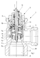
Figur 1- ein erfindungsgemäßes Durchflussregelventil mit integrierter Druckregelung im Zusammenbau im Mittellängsschnitt gesehen, in zwei unterschiedlichen Einstellungen;
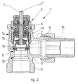
Figur 2- den Ventileinsatz der
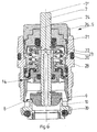
Figur 1 Figur 3- ein erfindungsgemäßes Durchflussregelventil mit integrierter Druckregelung im Zusammenbau im Mittelschnitt gesehen;
- Figur 4
- einen erfindungsgemäßen Ventileinsatz mit großem Voreinstellwert ebenfalls im Mittellängsschnitt gesehen;
Figur 5- den Schnitt A-A der
Figur 4 mit drehfest auf dem Einstellring montiertem Handrad und einem daran ausgebildeten, mit einem Zeiger korrespondierenden Anschlag; Figur 6- zeigt den Ventileinsatz gemäß
Figur4 mit kleinem Voreinstellwert ebenfalls im Mittellängsschnitt gesehen; Figur 7- zeigt eine Draufsicht auf den Ventileinsatz von oben gesehen;
Figur 8- zeigt einen Ventileinsatz mit separatem Voreinstellelement und Anschlussgeometrien zum Befestigen eines Stellantriebes in einer Ansicht analog
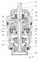
Figur 4 gesehen; Figur 9- ein erfindungsgemäßes Durchflussregelventil mit integrierter Druckregelung im Zusammenbau, im Mittellängsschnitt gesehen;
Figur 10- einen erfindungsgemäßen Ventileinsatz mit separatem Voreinstellelement, ebenfalls im Mittellängsschnitt gesehen;
Figur 11- eine Variante eines Ventileinsatzes mit separatem Voreinstellelement und Anschlussgeometrien zum Befestigen eines Stellantriebes, der auf die Spindel einwirken kann.
- FIG. 1
- an inventive flow control valve with integrated pressure control in the assembly seen in the central longitudinal section, in two different settings;
- FIG. 2
- the valve insert the
FIG. 1 without housing, also seen in two different stroke positions in central longitudinal section; - FIG. 3
- an inventive flow control valve with integrated pressure control in the assembly seen in the middle section;
- FIG. 4
- a valve insert according to the invention with a large preset value also seen in the central longitudinal section;
- FIG. 5
- the cut AA the
FIG. 4 with rotatably mounted on the adjusting ring handwheel and a trained thereon, with a pointer corresponding stop; - FIG. 6
- shows the valve insert according to
Figur4 also seen in the central longitudinal section with a small presetting value; - FIG. 7
- shows a plan view of the valve insert seen from above;
- FIG. 8
- shows a valve insert with a separate Voreinstellelement and connection geometries for fixing an actuator in a similar view
FIG. 4 seen; - FIG. 9
- an inventive flow control valve with integrated pressure control in assembly, seen in the central longitudinal section;
- FIG. 10
- a valve insert according to the invention with a separate Voreinstellelement, also seen in the central longitudinal section;
- FIG. 11
- a variant of a valve insert with a separate Voreinstellelement and connection geometries for securing an actuator that can act on the spindle.
In der Zeichnung ist ein Durchflussregelventil 1 für flüssigkeitsführende Heizungs- oder Kühlanlagen gezeigt. Es besteht aus einem ein- oder mehrteiligen Gehäuse 2, welches im Ausführungsbeispiel einen Einlass 3 und einen Auslass 4 aufweist. Zwischen Einlass 3 und Auslass 4 ist ein Anschlussstutzen 13 vorgesehen, in den eine Druckregeleinrichtung 14 eingebaut ist, welche die Druckdifferenz zwischen den Druckbereichen vor und hinter einer im Gehäuse 2 angeordneten Durchflussreguliereinheit 8 konstant hält. Des Weiteren ist eine Spindel 7 nach Art einer Ventilspindel angeordnet, die ein aus dem Gehäuse 2 nach oben abragendes Betätigungsteil aufweist. Auf das Gehäuse 2 ist ein Stellantrieb montierbar, wobei das Gehäuse eine Anschlussmöglichkeit 6 zum Anschließen eines solchen Stellantriebes aufweist. Der Stellantrieb wirkt auf das obere Ende der Spindel 7 ein und damit auf die Durchflussreguliereinheit 8 oder Teilen derselben. Damit wird der Strömungskanal durch das Ventil bzw. den später noch beschriebenen Ventileinsatz im Querschnitt verändert. Die Druckregeleinrichtung 14 umfasst die Spindel 7 koaxial und ist auf ihr axial beweglich angeordnet.In the drawing, a
Die Spindel 7 trägt an ihrem unteren Ende als Bestandteil einer ersten Drosseleinrichtung einen ersten Drosselkörper 9, der den Durchfluss bestimmt. Insbesondere besteht die Durchflussreguliereinheit 8 aus einer ersten Drosseleinrichtung mit dem an der Spindel 7 befestigten ersten Drosselkörper 9 und einem diesem zuzuordnenden Sitz 10. Ferner besteht die Durchflussreguliereinheit 8 aus einer zweiten Drosseleinrichtung, die aus einem auf der Spindel 7 längs dieser verstellbar angeordneten zweiten Drosselkörper 11 und einem diesem zuzuordnenden Sitz gebildet ist. Der zweite Drosselkörper 11 ist in Richtung auf den ersten Drosselkörper 9 zu diesem hin und von diesem weg beweglich. Hierdurch ist der Querschnitt des Strömungskanales durch das Durchflussregelventil 1 veränderbar.The
Insbesondere ist dabei auch vorgesehen, dass der erste Drosselkörper 9 gleichzeitig den Sitz für den zweiten Drosselkörper 11 bildet. Beispielsweise ist in der
Wie insbesondere auch die
Die Einzelteile sind dabei miteinander unverlierbar verbunden. Diese Ausgestaltung ermöglicht es unter anderem auch, bei im Markt befindlichen Thermostatventilen mit nicht-dynamischen Ventileinsätzen einen Austausch vorzunehmen, in dem der vorhandene Ventileinsatz gegen den erfindungsgemäßen Ventileinsatz 5 ausgetauscht wird.The items are connected to each other captive. This configuration makes it possible, among other things, to make an exchange in the market with thermostatic valves with non-dynamic valve inserts, in which the existing valve insert is replaced with the
Die Spindel 7 weist an ihrem oben aus dem Gehäuse 2 bzw. dem Stutzen 13 bzw. dem Ventileinsatz 5 vorragenden Endbereich eine drehfest an ihr angebrachte Handhabe zur Einstellung der zweiten Drosseleinrichtung auf. Der zweite Drosselkörper 11 ist dazu mit der Spindel 7 über eine Gewindeverbindung 16 gekoppelt. Zusätzlich ist der zweite Drosselkörper 11 an einem Bestandteil des Ventileinsatzes 5 oder dem Sitz 10 für den ersten Drosselkörper 9 parallel zur Spindellängserstreckung verstellbar und unverdrehbar gehalten und geführt. Es ist somit möglich, durch Drehung der Spindel 7 mittels der Handhabe 12 den zweiten Drosselkörper 11 in Richtung der Spindellängserstreckung zu verstellen.The
Vorzugsweise ist die Handhabe 12 lösbar an der Spindel 7 gehalten. Auch ist bevorzugt, dass die Handhabe 12 als Polygon ausgebildet ist und so eine Eingriffskontur für einen Stellschlüssel, beispielsweise einen Schraubenschlüssel bildet.Preferably, the
Zusätzlich ist vorgesehen, dass die Handhabe 12 mit ersten Markierungen für die Einstellposition versehen ist und am Gehäuse 2 oder vorzugsweise am Ventileinsatz 5 eine damit korrespondierende zweite Markierung vorgesehen ist. Damit ist es für den Benutzer in einfacher Weise möglich, die Voreinstellwerte genau einzustellen und abzulesen.In addition, it is provided that the
Die Druckregeleinrichtung 14 ist in an sich bekannter Weise ausgestaltet. Hierzu ist in einem Hohlraum des Ventileinsatzes 5 eine Membran 17 eingespannt gehalten, deren dem Betätigungsteil der Spindel 7 (in der Zeichnung oben) zugewandte Seite über einen in der Spindel 7 ausgebildeten ersten Kanal 18 mit dem Einlass 3 in leitungsoffener Verbindung steht. Deren der Durchflussreguliereinrichtung 8 zugewandte Seite steht über einen zweiten Kanal 19, der zur Durchflussreguliereinheit 8 hin offen ist, in Verbindung. In dieser Weise ist die Druckregelung in einfacher Weise in die Ausgestaltung des Ventileinsatzes 5 integriert.The
Die Erfindung stellt ein Durchflussregelventil 1 zur Verfügung, welches durch den Ventileinsatz 5 mit allen funktionellen Bestandteilen die Möglichkeit schafft, solche Teile bei kleinen Abmessungen kostengünstig herzustellen. Insbesondere sind solche Ventileinsätze 5 auch gegen herkömmliche Ventileinsätze in üblichen Thermostatventilen austauschbar.The invention provides a
In der Zeichnung, insbesondere in den
Die Spindel trägt an ihrem unteren Ende einen ersten Drosselkörper 9, durch den der Durchfluss bestimmt wird. Die Durchflussreguliereinheit 8 besteht somit aus einer Drosseleinrichtung mit dem an der Spindel 7 befestigten Drosselkörper 9 und einem diesen zugeordneten Sitz 10. Der Drosselkörper 9 bildet mit dem Sitz 10 einen Abstandsspalt 15, der zum Auslass 4 hin offen ist, so dass ein entsprechender Durchfluss durch das Ventil möglich ist.The spindle carries at its lower end a
Wie insbesondere die
Die Druckregeleinrichtung 14 ist in an sich bekannter Weise ausgestaltet. Dabei ist in einem Hohlraum des Ventileinsatzes 5 eine Membran 17 eingespannt gehalten, deren dem Betätigungsteil der Spindel 7 (in der Zeichnung oben) zugewandte Seite über einen in der Spindel 7 ausgebildeten ersten Kanal 18 mit dem Einlass 3 in leitungsoffener Verbindung steht. Deren der Durchflussreguliereinrichtung 8 zugewandte Seite steht über einen zweiten Kanal 19, der zur Durchflussreguliereinheit 8 hin offen ist, in Verbindung. Somit ist in einfacher Weise die Druckregelung in die Ausgestaltung des Ventileinsatzes 5 integriert.The
Der Ventileinsatz 5 weist besonders kompakte Außenabmessungen und damit eine möglichst geringe Eintauchtiefe in das Gehäuse 2 des Thermostatventiles auf, so dass die Rohranschlussgeometrien 13 des Gehäuses 2 nicht durch den Ventileinsatz 5 verdeckt werden, wenn der Ventileinsatz 5 als Einheit in das Gehäuse montiert oder daraus demontiert wird.The
Durch die Hubbegrenzung des Drosselkörpers 9 wird eine Voreinstellung der Durchflussreguliereinheit 8 erreicht, so dass der Fluidstrom auf einen maximalen Wert begrenzt werden kann, der mit der eingestellten Hubhöhe des Drosselkörpers 9 korrespondiert.By the stroke limitation of the
Die Druckregeleinrichtung 14 umgreift die mit dem Drosselkörper 9 gekoppelte Spindel koaxial und ist auf dieser axial beweglich angeordnet, so dass wiederum eine kompakte montierbare Einheit besteht.The
Zum Zwecke der Hubbegrenzung weist die Spindel 7 mindestens einen radial vorstehenden Kragen 20 oder Absatz auf, der mit einem an einem axial beweglichen Einstellring 21 angebrachten Anschlag 22 zur Anlage gelangen kann. Der axial bewegliche Einstellring 21 umgreift die Spindel 7 koaxial. Zusätzlich ist im Ausführungsbeispiel der Einstellring 21 mit einem Gewinde 23 versehen, welches die Drehbewegung in eine Hubbewegung umwandelt. Des Weiteren ist der Einstellring 21 mit einem daran drehfest gekoppelten Handrad 24 versehen. Dieses Handrad 24 weist eine Skala 25 zum Ablesen der Voreinstellwerte auf, die mit einem am Ventileinsatz 5 angebrachten Zeiger 26 korrespondiert. Die Drehbewegung des Handrades 24 wird durch einen an dem Handrad 24 ausgebildeten und mit dem Zeiger 26 korrespondierenden Anschlag 27 begrenzt. Zusätzlich kann das Ventileinsatzgehäuse 28, wie in
Zum Zwecke der Hubbegrenzung können die entsprechenden Elemente eingestellt werden, wie dies in den Zeichnungsfiguren ersichtlich ist, beispielsweise in eine Position gemäß
Zusätzlich ist zur Vermeidung von Verschmutzungen, die die Funktion des Ventileinsatzes 5 beeinträchtigen könnten, vorgesehen, dass unterhalb des Ventilsitzes 10 des Ventileinsatzes 5 ein Filtersieb 30 vorgesehen ist, welches gegebenenfalls lösbar befestigt, also auswechselbar angeordnet ist.In addition, to prevent contamination that could affect the function of the
Insbesondere durch die Ausbildung der Hubbegrenzungsmittel für den Hub des Drosselkörpers wird eine besonders kompakte Bauform des Ventileinsatzes 5 gefördert, so dass ein solcher Ventileinsatz 5 gegen herkömmliche Ventileinsätze in üblichen Thermostatventilen ausgetauscht werden kann.In particular, by the formation of the Hubbegrenzungsmittel for the stroke of the throttle body a particularly compact design of the
In der Zeichnung (
Die Spindel 7 trägt an ihrem unteren Ende als Bestandteil einer ersten Drosseleinrichtung einen ersten Drosselkörper 9, der den Durchfluss bestimmt. Insbesondere besteht die Durchflussreguliereinheit 8 aus einer ersten Drosseleinrichtung mit dem an der Spindel 7 befestigten ersten Drosselkörper 9 und einem diesen zuzuordnenden Sitz 10. Ferner besteht die Durchflussreguliereinrichtung aus einer zweiten Drosseleinrichtung, die aus einem in einem Kragen 39 axial verstellbar angeordneten zweiten Drosselkörper 11 besteht, der dem Drosselkörper 9 zugeordnet ist. Je nach Einstellung des zweiten Drosselkörpers 11 relativ zum ersten Drosselkörper 9 ist der Querschnitt des Strömungsspaltes 15 veränderbar.The
Sämtliche Teile, nämlich die Druckregeleinrichtung 14, die Ventilspindel 7 mit ihrem Drosselkörper 9, die Durchflussreguliereinheit 8 mit der ersten Drosseleinrichtung und der zweiten Drosseleinrichtung samt zweiten Drosselkörper 11 und den zugehörigen Sitzen für die Drosselkörper als Ventileinheit 5 zu einer Montageeinheit zusammengefasst, die als solche komplett in den Anschlussstutzen 13 des Gehäuses 2 als Einheit eingeschoben und montiert werden kann oder auch demontiert werden kann. Die Einzelteile sind dabei miteinander unverlierbar verbunden. Diese Ausgestaltung ermöglicht es unter anderem auch, bei im Markt befindlichen Thermostatventilen mit nicht-dynamischen Ventileinsätzen einen Austausch vorzunehmen, indem der vorhandene Ventileinsatz gegen den Erfindungs- Ventileinsatz 5 ausgetauscht wird.All parts, namely the
Die in den Ventileinsatz 5 integrierte Druckregeleinrichtung 14 ist in an sich bekannter Weise ausgestaltet. Hierzu ist in einem Hohlraum des Ventileinsatzes 5 eine Membran 17 eingespannt gehalten, deren den Betätigungsteil der Spindel 7 (in der Zeichnung oben) zugewandten Seite über einen in der Spindel 7 ausgebildeten ersten Kanal 18 mit dem Einlass 3 in leitungsoffener Verbindung steht. Deren der Durchflussreguliereinrichtung 8 zugewandten Seite steht über einen zweiten Kanal 19, der zur Durchflussreguliereinheit 8 hin offen ist, in Verbindung. In dieser Weise ist die Druckregelung in einfacher Weise in die Ausgestaltung des Ventileinsatzes 5 integriert.The integrated into the
Des Weiteren ist eine Sollwertfeder 32 der Druckreguliereinrichtung 14 auf der dem Strömungskanal oder Spalt 15 abgewandten Seite der Membran 17 und der dem Betätigungsteil 7' der Spindel 7 zugewandten Seite angeordnet. Des Weiteren ist eine Ventilfeder 33 angeordnet, die die Sollwertfeder 32 koaxial umfasst. Auf diese Weise ist der Einbauraum für beide Federn klein gehalten, so dass die kompakte Bauform des Ventileinsatzes 5 erreicht wird und erreicht wird, dass dieser in vorhandene Ventilgehäuse oben angegebener Art eingebaut werden kann.Furthermore, a desired
Insbesondere ist so die Druckregeleinrichtung 14 und die Durchflussregeleinrichtung 8 samt Ventilfeder 33 und Sollwertfeder 32 als Bestandteil des Ventileinsatzes 5 zu einer Montageeinheit unverlierbar miteinander verbunden, so dass der Ventileinsatz 5 als komplette Einbaueinheit in das Gehäuse 2 montierbar oder daraus montierbar ist.In particular, the
Im Ausführungsbeispiel stützen sich sowohl die Sollwertfeder 32 als auch die Ventilfeder 33 auf einem gemeinsamen in dem Ventileinsatz 5 befindlichen Halteelement 34 ab, was für die kompakte Bauform förderlich ist. Dieses Halteelement 34 bildet außerdem eine die Membran 17 stützende Kontur 35 aus, die einen Einbauraum 36 für den äußeren Dichtwulst 37 der Membrane 17 bildet. Das Halteelement 34 ist durch eine kraft- oder formschlüssige Verbindung 38 mit dem Ventileinsatzgehäuse 28 verbunden. ImIn the exemplary embodiment, both the
Ausführungsbeispiel gemäß
Ventileinsatzgehäuse 28 eine Anschlussgeometrie 29 für das Befestigen von Stellgliedern auf, welche auf dem Betätigungsteil 7' der Ventilspindel 7 einwirken können.Valve insert
Zusätzlich weist der Sitz 10 des Ventileinsatzes 5 einen Kragen 39 auf. In diesem Kragen ist unterhalb des ersten Drosselkörpers 9 ein voreinstellbarer zweiter Drosselkörper 11 angeordnet. Dieser ist geeigneter Weise axial verstellbar, beispielsweise durch Drehung der mit dem Drosselkörper 11 gekoppelten Spindel 7.In addition, the
Zusätzlich ist der Sitz 10 des Ventileinsatzes 5 auf seiner Unterseite mit einem Filtersieb 30 ausgestattet, welches vorzugsweise auswechselbar angeordnet ist.In addition, the
Die Erfindung ist nicht auf die Ausführungsbeispiele beschränkt, sondern im Rahmen der Offenbarung vielfach variabel.The invention is not limited to the embodiments, but in the context of the disclosure often variable.
Alle in der Beschreibung und/oder Zeichnung offenbarten Einzel- und Kombinationsmerkmale werden als erfindungswesentlich angesehen.All disclosed in the description and / or drawing single and combination features are considered essential to the invention.
- 11
- DurchflussregelventilFlow control valve
- 22
- Gehäusecasing
- 33
- Einlassinlet
- 44
- Auslassoutlet
- 55
- Ventileinsatzvalve core
- 66
- Anschlussmöglichkeit (für Stellantrieb)Connection possibility (for actuator)
- 77
- Spindelspindle
- 7'7 '
- Spindelendespindle end
- 88th
- DurchflussreguliereinheitDurchflussreguliereinheit
- 99
- erster Drosselkörperfirst throttle body
- 1010
- Sitz für 9Seat for 9
- 1111
- zweiter Drosselkörpersecond throttle body
- 1212
- Handhabehandle
- 1313
- Anschlussstutzenspigot
- 1414
- DruckregeleinrichtungPressure control device
- 1515
- Spaltgap
- 1616
- Gewindeverbindungthreaded connection
- 1717
- Membranmembrane
- 1818
- erster Kanalfirst channel
- 1919
- zweiter Kanalsecond channel
- 2020
- Kragencollar
- 2121
- Einstellringadjustment
- 2222
- Anschlagattack
- 2323
- Gewindethread
- 2424
- Handradhandwheel
- 2525
- Skalascale
- 2626
- Zeigerpointer
- 2727
- Anschlag für 26Stop for 26
- 2828
- VentileinsatzgehäuseValve core housing
- 2929
- Anschlussgeometrieconnection geometry
- 3030
- Filtersiebfilter screen
- 3131
- RohranschlussgeometrieTube connection geometry
- 3232
- SollwertfeldSetpoint field
- 3333
- Ventilfedervalve spring
- 3434
- Halteelementretaining element
- 3535
- Konturcontour
Claims (10)
Priority Applications (1)
| Application Number | Priority Date | Filing Date | Title |
|---|---|---|---|
| PL16171000T PL3104246T3 (en) | 2013-07-22 | 2014-07-01 | Flow control valve |
Applications Claiming Priority (5)
| Application Number | Priority Date | Filing Date | Title |
|---|---|---|---|
| DE102013107762.5A DE102013107762A1 (en) | 2013-07-22 | 2013-07-22 | Flow control valve |
| DE102014103051 | 2014-03-07 | ||
| DE102014004910.8A DE102014004910A1 (en) | 2014-03-07 | 2014-04-04 | Flow control valve |
| DE102014004907.8A DE102014004907A1 (en) | 2014-04-04 | 2014-04-04 | Flow control valve |
| EP14766889.1A EP3025207B1 (en) | 2013-07-22 | 2014-07-01 | Flow regulating valve |
Related Parent Applications (2)
| Application Number | Title | Priority Date | Filing Date |
|---|---|---|---|
| EP14766889.1A Division EP3025207B1 (en) | 2013-07-22 | 2014-07-01 | Flow regulating valve |
| EP14766889.1A Division-Into EP3025207B1 (en) | 2013-07-22 | 2014-07-01 | Flow regulating valve |
Publications (2)
| Publication Number | Publication Date |
|---|---|
| EP3104246A1 true EP3104246A1 (en) | 2016-12-14 |
| EP3104246B1 EP3104246B1 (en) | 2017-10-11 |
Family
ID=55178593
Family Applications (2)
| Application Number | Title | Priority Date | Filing Date |
|---|---|---|---|
| EP14766889.1A Active EP3025207B1 (en) | 2013-07-22 | 2014-07-01 | Flow regulating valve |
| EP16171000.9A Active EP3104246B1 (en) | 2013-07-22 | 2014-07-01 | Flow control valve |
Family Applications Before (1)
| Application Number | Title | Priority Date | Filing Date |
|---|---|---|---|
| EP14766889.1A Active EP3025207B1 (en) | 2013-07-22 | 2014-07-01 | Flow regulating valve |
Country Status (14)
| Country | Link |
|---|---|
| US (1) | US10139839B2 (en) |
| EP (2) | EP3025207B1 (en) |
| JP (1) | JP6214114B2 (en) |
| KR (1) | KR102176610B1 (en) |
| CN (1) | CN105593584B (en) |
| AU (2) | AU2014295508B2 (en) |
| BR (1) | BR112016001415B1 (en) |
| CA (2) | CA2964261C (en) |
| DK (2) | DK3025207T3 (en) |
| ES (2) | ES2625413T3 (en) |
| HK (1) | HK1222443A1 (en) |
| PL (2) | PL3025207T3 (en) |
| RU (1) | RU2637074C2 (en) |
| WO (1) | WO2015010685A2 (en) |
Families Citing this family (21)
| Publication number | Priority date | Publication date | Assignee | Title |
|---|---|---|---|---|
| ES2625413T3 (en) * | 2013-07-22 | 2017-07-19 | Oventrop Gmbh & Co. Kg | Flow control valve |
| DE102014110550B4 (en) | 2014-07-25 | 2017-07-13 | Oventrop Gmbh & Co. Kg | control valve |
| US9910447B2 (en) * | 2015-03-10 | 2018-03-06 | Fratelli Pettinaroli S.P.A. | Automatic balancing valve |
| EP3418847B1 (en) | 2016-03-24 | 2022-01-26 | Honeywell Technologies Sarl | Flow regulation valve |
| US20190257560A1 (en) * | 2016-05-10 | 2019-08-22 | Byd Company Limited | Expansion switch valve |
| CN106122570A (en) * | 2016-08-04 | 2016-11-16 | 上海申吉仪表有限公司 | Diesel coolant bypass valve |
| DE102016125734A1 (en) * | 2016-12-27 | 2018-06-28 | Oventrop Gmbh & Co. Kg | control valve |
| DE102017102308A1 (en) | 2017-02-07 | 2018-08-09 | Oventrop Gmbh & Co. Kg | Valve with a device for presetting the flow channel cross-section |
| EP3432112B1 (en) * | 2017-07-20 | 2021-12-08 | Danfoss A/S | Valve arrangement for controlling of flow of a heating or cooling fluid |
| CN111033099B (en) * | 2017-08-14 | 2022-02-18 | 弗洛康国际有限公司 | Control valve for heating and/or cooling system |
| KR101959992B1 (en) * | 2018-01-31 | 2019-03-20 | 주식회사 브이오텍 | A flow adjusting valve for heating water distribution device |
| DK3527862T3 (en) | 2018-02-19 | 2021-01-25 | Oventrop Gmbh & Co Kg | Valve with a device for presetting the flow channel cross section |
| DE102018204584A1 (en) * | 2018-03-26 | 2019-09-26 | Coperion Gmbh | Start-up throttle device for discharging a melt from a screw machine and plant for the treatment of bulk material with such a start-throttle valve device and method for discharging a melt from a screw machine by means of such a starting valve throttle device |
| EP3575915B1 (en) | 2018-05-28 | 2021-07-21 | Honeywell Technologies Sarl | Flow regulation valve and method for calibrating the same |
| ES2923513T3 (en) | 2018-07-27 | 2022-09-28 | Ideal Standard Int Nv | Sanitary valve with membrane valve |
| CN109236614B (en) * | 2018-11-01 | 2023-10-17 | 南京尚爱机械制造有限公司 | Temperature control valve for controlling cooling water flow of cylinder of piston compressor |
| IT201900003389A1 (en) * | 2019-03-08 | 2020-09-08 | Giacomini Spa | CARTRIDGE REGULATION GROUP WITH COMPENSATION CHAMBER AND HYDRAULIC VALVE INCLUDING THE CARTRIDGE REGULATION GROUP. |
| US11499726B2 (en) * | 2019-09-17 | 2022-11-15 | Emerson Electric Co. | Coaxial gas valve assemblies including electronically controlled solenoids |
| KR102150463B1 (en) * | 2020-02-03 | 2020-09-01 | 신동민 | system for controlling fluid pressure by adjusting tension force |
| CN112555425A (en) * | 2020-11-30 | 2021-03-26 | 广州皖安机电设备有限公司 | Hydraulic valve capable of adjusting liquid flow |
| EP4296548A1 (en) * | 2022-06-22 | 2023-12-27 | Flühs Drehtechnik GmbH | Upper part of a valve |
Citations (9)
| Publication number | Priority date | Publication date | Assignee | Title |
|---|---|---|---|---|
| EP0751448A2 (en) * | 1995-06-28 | 1997-01-02 | Landis & Gyr Technology Innovation AG | Flow control valve |
| EP0911714A1 (en) * | 1997-10-20 | 1999-04-28 | Electrowatt Technology Innovation AG | Flow control valve with integrated pressure controller |
| DE10256035B3 (en) | 2002-11-30 | 2004-09-09 | Danfoss A/S | Control valve for heat exchanger or heater has valve body screwed onto seat by spindle and has pressure regulating valve with opening spring and diaphragm |
| DE102007013505A1 (en) * | 2007-03-21 | 2008-10-02 | F.W. Oventrop Gmbh & Co. Kg | Armature combination for use in liquid-containing heating or cooling system, has flow cross-section adjusted with actuator by handle, where state of handle is read on indicator that indicates pre-adjustment of flow cross-section |
| WO2009135490A2 (en) | 2008-05-05 | 2009-11-12 | Frese A/S | A control valve |
| DE102009011506A1 (en) * | 2009-03-06 | 2010-09-16 | F.W. Oventrop Gmbh & Co. Kg | Flow control valve for heating and cooling systems |
| DE102011107273A1 (en) * | 2011-07-15 | 2013-01-17 | Robert Bosch Gmbh | Control valve device for controlling fluid flow between mass flow restrictor and differential pressure regulator, has flow restrictor and regulator that are arranged within channel and are displaced opposite to its opening directions |
| EP2615342A1 (en) * | 2012-01-13 | 2013-07-17 | Fluid Handling LLC. | Flow rate scale field calibration for balancing valve |
| DE102007050454B4 (en) | 2007-10-19 | 2013-08-22 | Danfoss A/S | regulating |
Family Cites Families (38)
| Publication number | Priority date | Publication date | Assignee | Title |
|---|---|---|---|---|
| US2474430A (en) * | 1949-06-28 | Valve | ||
| US1507874A (en) * | 1924-09-09 | Orchard valve | ||
| US1502650A (en) * | 1921-06-16 | 1924-07-29 | Nathan Mfg Co | Gauge cock |
| US1467464A (en) * | 1921-09-29 | 1923-09-11 | Hampden Brass Company | Safety faucet |
| US1563590A (en) * | 1923-11-02 | 1925-12-01 | Herman W Rottel | Valve |
| US1674074A (en) * | 1925-04-27 | 1928-06-19 | Orrey A Turner | Irrigating valve |
| US1631564A (en) * | 1925-07-14 | 1927-06-07 | Diederik Lodewijk Hendr Raalte | Valve for making connection between underground main piping and underground branch piping |
| US1678927A (en) * | 1927-04-13 | 1928-07-31 | Jr Albert J Weatherhead | Drain cock or valve |
| US1821422A (en) * | 1928-08-09 | 1931-09-01 | Edna Brass Mfg Company | Gauge cock |
| US2029202A (en) * | 1935-08-28 | 1936-01-28 | Chester G Shepherd | High pressure safety gauge cock |
| US2211068A (en) * | 1937-12-24 | 1940-08-13 | Albert E Vandercock | Method and apparatus for classifying solids |
| US2377227A (en) * | 1941-06-04 | 1945-05-29 | Donald G Griswold | Pressure responsive valve |
| US2339421A (en) * | 1941-09-30 | 1944-01-18 | Westinghouse Air Brake Co | Pilot mechanism |
| US2374690A (en) * | 1942-02-09 | 1945-05-01 | Charles E Laue | Valve |
| US2403689A (en) * | 1942-08-28 | 1946-07-09 | Hoof Products Company | Fluid lockout device |
| US2414911A (en) * | 1944-02-03 | 1947-01-28 | Temple Velocity Equipment Inc | Emergency valve |
| US2473704A (en) * | 1947-10-01 | 1949-06-21 | Phillips Petroleum Co | Hose connector and valve |
| US2655946A (en) * | 1949-06-02 | 1953-10-20 | Melvin P Morris | Valve for leak patching device for pipe lines |
| US2623331A (en) * | 1950-08-01 | 1952-12-30 | Agro Phosphate Company | Diaphragm type of pressure regulators |
| US2916047A (en) * | 1952-12-22 | 1959-12-08 | Kenneth L Butcher | Automatic regulation of the rate of flow of a fluid through a pipe or the like |
| US3532104A (en) * | 1968-01-24 | 1970-10-06 | Kenneth H Hoen | Pressure compensated flow control valve system |
| US3948481A (en) * | 1974-05-02 | 1976-04-06 | The Weatherhead Company | Draincock for automotive cooling system |
| CA1051508A (en) * | 1975-03-07 | 1979-03-27 | Continental Oil Company | Port closure apparatus for differentially pressured vessels |
| US4418888A (en) * | 1981-06-08 | 1983-12-06 | Perfection Corporation | Angle cock valve |
| US4703776A (en) * | 1986-02-12 | 1987-11-03 | Rumney Roger E | Snow hydrant |
| SU1493982A1 (en) * | 1987-04-13 | 1989-07-15 | Винницкий политехнический институт | Flow rate controller |
| JPH0720727Y2 (en) * | 1989-05-29 | 1995-05-15 | フシマン株式会社 | Cartridge type pressure control valve |
| JP2803969B2 (en) * | 1993-05-20 | 1998-09-24 | 株式会社クボタ | Variable constant flow valve |
| US5642752A (en) * | 1993-08-23 | 1997-07-01 | Kabushiki Kaisha Yokota Seisakusho | Controllable constant flow regulating lift valve |
| US6062540A (en) * | 1998-11-10 | 2000-05-16 | Thomas Industries Inc. | Double seal drain cock |
| KR20020081638A (en) * | 2001-04-20 | 2002-10-30 | 송정석 | Form power of recollection spring to use solenoid valae |
| JP2005132347A (en) * | 2003-10-10 | 2005-05-26 | Advics:Kk | Braking fluid control device |
| RU43636U1 (en) * | 2004-08-09 | 2005-01-27 | Общество с ограниченной ответственностью "Научно-производственный центр ОСТА" (ООО "НПЦ ОСТА") | AUTOMATED LIQUID FLOW REGULATOR |
| US7681589B2 (en) * | 2006-06-21 | 2010-03-23 | Fmc Technologies, Inc. | Pump valve retainer |
| KR101221574B1 (en) * | 2008-04-18 | 2013-01-16 | 오벤트롭 게엠베하 운트 코. 카게 | Valve combination for regulating the flow rate or differential pressure |
| US8800597B2 (en) * | 2011-04-15 | 2014-08-12 | Graco Minnesota Inc. | Fine control gas valve |
| US8746283B2 (en) * | 2011-10-03 | 2014-06-10 | Aquasana, Inc. | Faucet diverter valves |
| ES2625413T3 (en) * | 2013-07-22 | 2017-07-19 | Oventrop Gmbh & Co. Kg | Flow control valve |
-
2014
- 2014-07-01 ES ES14766889.1T patent/ES2625413T3/en active Active
- 2014-07-01 PL PL14766889T patent/PL3025207T3/en unknown
- 2014-07-01 AU AU2014295508A patent/AU2014295508B2/en active Active
- 2014-07-01 JP JP2016528357A patent/JP6214114B2/en active Active
- 2014-07-01 BR BR112016001415-4A patent/BR112016001415B1/en not_active IP Right Cessation
- 2014-07-01 ES ES16171000.9T patent/ES2648314T3/en active Active
- 2014-07-01 CA CA2964261A patent/CA2964261C/en active Active
- 2014-07-01 US US14/901,433 patent/US10139839B2/en active Active
- 2014-07-01 CN CN201480041790.6A patent/CN105593584B/en active Active
- 2014-07-01 EP EP14766889.1A patent/EP3025207B1/en active Active
- 2014-07-01 EP EP16171000.9A patent/EP3104246B1/en active Active
- 2014-07-01 CA CA2918351A patent/CA2918351C/en active Active
- 2014-07-01 KR KR1020167004537A patent/KR102176610B1/en active IP Right Grant
- 2014-07-01 WO PCT/DE2014/100223 patent/WO2015010685A2/en active Application Filing
- 2014-07-01 DK DK14766889.1T patent/DK3025207T3/en active
- 2014-07-01 RU RU2016105690A patent/RU2637074C2/en active
- 2014-07-01 DK DK16171000.9T patent/DK3104246T3/en active
- 2014-07-01 PL PL16171000T patent/PL3104246T3/en unknown
-
2016
- 2016-08-04 AU AU2016210690A patent/AU2016210690B2/en active Active
- 2016-09-06 HK HK16110563.8A patent/HK1222443A1/en unknown
Patent Citations (9)
| Publication number | Priority date | Publication date | Assignee | Title |
|---|---|---|---|---|
| EP0751448A2 (en) * | 1995-06-28 | 1997-01-02 | Landis & Gyr Technology Innovation AG | Flow control valve |
| EP0911714A1 (en) * | 1997-10-20 | 1999-04-28 | Electrowatt Technology Innovation AG | Flow control valve with integrated pressure controller |
| DE10256035B3 (en) | 2002-11-30 | 2004-09-09 | Danfoss A/S | Control valve for heat exchanger or heater has valve body screwed onto seat by spindle and has pressure regulating valve with opening spring and diaphragm |
| DE102007013505A1 (en) * | 2007-03-21 | 2008-10-02 | F.W. Oventrop Gmbh & Co. Kg | Armature combination for use in liquid-containing heating or cooling system, has flow cross-section adjusted with actuator by handle, where state of handle is read on indicator that indicates pre-adjustment of flow cross-section |
| DE102007050454B4 (en) | 2007-10-19 | 2013-08-22 | Danfoss A/S | regulating |
| WO2009135490A2 (en) | 2008-05-05 | 2009-11-12 | Frese A/S | A control valve |
| DE102009011506A1 (en) * | 2009-03-06 | 2010-09-16 | F.W. Oventrop Gmbh & Co. Kg | Flow control valve for heating and cooling systems |
| DE102011107273A1 (en) * | 2011-07-15 | 2013-01-17 | Robert Bosch Gmbh | Control valve device for controlling fluid flow between mass flow restrictor and differential pressure regulator, has flow restrictor and regulator that are arranged within channel and are displaced opposite to its opening directions |
| EP2615342A1 (en) * | 2012-01-13 | 2013-07-17 | Fluid Handling LLC. | Flow rate scale field calibration for balancing valve |
Also Published As
| Publication number | Publication date |
|---|---|
| CA2918351A1 (en) | 2015-01-29 |
| PL3104246T3 (en) | 2018-03-30 |
| HK1222443A1 (en) | 2017-06-30 |
| US10139839B2 (en) | 2018-11-27 |
| AU2016210690B2 (en) | 2017-11-16 |
| JP6214114B2 (en) | 2017-10-18 |
| DK3104246T3 (en) | 2018-01-15 |
| AU2016210690A1 (en) | 2016-08-25 |
| CN105593584B (en) | 2018-04-13 |
| RU2637074C2 (en) | 2017-11-29 |
| PL3025207T3 (en) | 2017-09-29 |
| AU2014295508B2 (en) | 2016-09-22 |
| BR112016001415B1 (en) | 2021-05-04 |
| EP3104246B1 (en) | 2017-10-11 |
| EP3025207A2 (en) | 2016-06-01 |
| RU2016105690A (en) | 2017-08-23 |
| ES2648314T3 (en) | 2017-12-29 |
| JP2016530461A (en) | 2016-09-29 |
| AU2014295508A1 (en) | 2016-02-18 |
| KR102176610B1 (en) | 2020-11-09 |
| CA2964261A1 (en) | 2015-01-22 |
| WO2015010685A2 (en) | 2015-01-29 |
| ES2625413T3 (en) | 2017-07-19 |
| CA2918351C (en) | 2019-08-13 |
| EP3025207B1 (en) | 2017-04-19 |
| CN105593584A (en) | 2016-05-18 |
| BR112016001415A2 (en) | 2017-08-29 |
| WO2015010685A3 (en) | 2015-10-22 |
| US20160139606A1 (en) | 2016-05-19 |
| KR20160033223A (en) | 2016-03-25 |
| CA2964261C (en) | 2019-09-03 |
| DK3025207T3 (en) | 2017-07-31 |
Similar Documents
| Publication | Publication Date | Title |
|---|---|---|
| EP3104246B1 (en) | Flow control valve | |
| EP2271969B1 (en) | Valve combination for regulating the flow rate or differential pressure | |
| EP3172634B1 (en) | Regulating valve | |
| EP2536886B1 (en) | Sanitary insert for spout | |
| DE102009011343B4 (en) | Flow regulator | |
| DE102010021483A1 (en) | Sanitary embedded component for use in water outlet portion of sanitary water outlet valve, has regulating device operated via operational element, which is operationally arranged on inflow side and/or outflow side of component | |
| DE202005004196U1 (en) | Flow regulator | |
| DE102013107762A1 (en) | Flow control valve | |
| EP1780452A2 (en) | Pressure reducer | |
| EP0119503B1 (en) | Temperature-dependent controllable heating valve with a preset device | |
| DE4416154C2 (en) | Flow control valve | |
| DE4042074C1 (en) | ||
| DE102006026336B4 (en) | Built-in valve for a radiator | |
| DE2442482C3 (en) | Valve arrangement for controlling the water supply to one or more water dispensing points | |
| EP3217103B1 (en) | Valve insert for a radiator valve and radiator having radiator valve | |
| DE102005011947B3 (en) | Continuous flow controller, has controlling mechanisms designed for different flow rate capacities and/or pressure ranges, where one mechanism exhibits opening that acts as bypass channel, which is openable and closeable | |
| DE102014004907A1 (en) | Flow control valve | |
| DE102006059577B4 (en) | Valve | |
| DE102007013505A1 (en) | Armature combination for use in liquid-containing heating or cooling system, has flow cross-section adjusted with actuator by handle, where state of handle is read on indicator that indicates pre-adjustment of flow cross-section | |
| DE102014004910A1 (en) | Flow control valve | |
| DE1813599A1 (en) | Valves, especially faucets, with a large change in flow rates | |
| EP3527862B1 (en) | Valve with a device for presetting the flow channel cross-section | |
| EP1965110A1 (en) | Sanitary mix fitting with a fitting case and a control cartridge positioned in this case | |
| DE102017102308A1 (en) | Valve with a device for presetting the flow channel cross-section | |
| EP0610703A2 (en) | Regulation device |
Legal Events
| Date | Code | Title | Description |
|---|---|---|---|
| PUAI | Public reference made under article 153(3) epc to a published international application that has entered the european phase |
Free format text: ORIGINAL CODE: 0009012 |
|
| 17P | Request for examination filed |
Effective date: 20160524 |
|
| AC | Divisional application: reference to earlier application |
Ref document number: 3025207 Country of ref document: EP Kind code of ref document: P |
|
| AK | Designated contracting states |
Kind code of ref document: A1 Designated state(s): AL AT BE BG CH CY CZ DE DK EE ES FI FR GB GR HR HU IE IS IT LI LT LU LV MC MK MT NL NO PL PT RO RS SE SI SK SM TR |
|
| AX | Request for extension of the european patent |
Extension state: BA ME |
|
| GRAP | Despatch of communication of intention to grant a patent |
Free format text: ORIGINAL CODE: EPIDOSNIGR1 |
|
| RIC1 | Information provided on ipc code assigned before grant |
Ipc: F16K 1/52 20060101ALI20170524BHEP Ipc: F16K 1/44 20060101ALI20170524BHEP Ipc: G05D 7/01 20060101AFI20170524BHEP Ipc: F24D 19/10 20060101ALI20170524BHEP |
|
| INTG | Intention to grant announced |
Effective date: 20170613 |
|
| GRAS | Grant fee paid |
Free format text: ORIGINAL CODE: EPIDOSNIGR3 |
|
| GRAA | (expected) grant |
Free format text: ORIGINAL CODE: 0009210 |
|
| AC | Divisional application: reference to earlier application |
Ref document number: 3025207 Country of ref document: EP Kind code of ref document: P |
|
| AK | Designated contracting states |
Kind code of ref document: B1 Designated state(s): AL AT BE BG CH CY CZ DE DK EE ES FI FR GB GR HR HU IE IS IT LI LT LU LV MC MK MT NL NO PL PT RO RS SE SI SK SM TR |
|
| REG | Reference to a national code |
Ref country code: GB Ref legal event code: FG4D Free format text: NOT ENGLISH |
|
| REG | Reference to a national code |
Ref country code: CH Ref legal event code: EP |
|
| REG | Reference to a national code |
Ref country code: CH Ref legal event code: NV Representative=s name: TROESCH SCHEIDEGGER WERNER AG, CH |
|
| REG | Reference to a national code |
Ref country code: IE Ref legal event code: FG4D Free format text: LANGUAGE OF EP DOCUMENT: GERMAN |
|
| REG | Reference to a national code |
Ref country code: AT Ref legal event code: REF Ref document number: 936587 Country of ref document: AT Kind code of ref document: T Effective date: 20171115 |
|
| REG | Reference to a national code |
Ref country code: DE Ref legal event code: R096 Ref document number: 502014005825 Country of ref document: DE |
|
| REG | Reference to a national code |
Ref country code: NL Ref legal event code: FP |
|
| REG | Reference to a national code |
Ref country code: ES Ref legal event code: FG2A Ref document number: 2648314 Country of ref document: ES Kind code of ref document: T3 Effective date: 20171229 |
|
| REG | Reference to a national code |
Ref country code: DK Ref legal event code: T3 Effective date: 20180110 |
|
| REG | Reference to a national code |
Ref country code: LT Ref legal event code: MG4D |
|
| PG25 | Lapsed in a contracting state [announced via postgrant information from national office to epo] |
Ref country code: NO Free format text: LAPSE BECAUSE OF FAILURE TO SUBMIT A TRANSLATION OF THE DESCRIPTION OR TO PAY THE FEE WITHIN THE PRESCRIBED TIME-LIMIT Effective date: 20180111 Ref country code: LT Free format text: LAPSE BECAUSE OF FAILURE TO SUBMIT A TRANSLATION OF THE DESCRIPTION OR TO PAY THE FEE WITHIN THE PRESCRIBED TIME-LIMIT Effective date: 20171011 Ref country code: SE Free format text: LAPSE BECAUSE OF FAILURE TO SUBMIT A TRANSLATION OF THE DESCRIPTION OR TO PAY THE FEE WITHIN THE PRESCRIBED TIME-LIMIT Effective date: 20171011 Ref country code: FI Free format text: LAPSE BECAUSE OF FAILURE TO SUBMIT A TRANSLATION OF THE DESCRIPTION OR TO PAY THE FEE WITHIN THE PRESCRIBED TIME-LIMIT Effective date: 20171011 |
|
| PG25 | Lapsed in a contracting state [announced via postgrant information from national office to epo] |
Ref country code: HR Free format text: LAPSE BECAUSE OF FAILURE TO SUBMIT A TRANSLATION OF THE DESCRIPTION OR TO PAY THE FEE WITHIN THE PRESCRIBED TIME-LIMIT Effective date: 20171011 Ref country code: GR Free format text: LAPSE BECAUSE OF FAILURE TO SUBMIT A TRANSLATION OF THE DESCRIPTION OR TO PAY THE FEE WITHIN THE PRESCRIBED TIME-LIMIT Effective date: 20180112 Ref country code: RS Free format text: LAPSE BECAUSE OF FAILURE TO SUBMIT A TRANSLATION OF THE DESCRIPTION OR TO PAY THE FEE WITHIN THE PRESCRIBED TIME-LIMIT Effective date: 20171011 Ref country code: BG Free format text: LAPSE BECAUSE OF FAILURE TO SUBMIT A TRANSLATION OF THE DESCRIPTION OR TO PAY THE FEE WITHIN THE PRESCRIBED TIME-LIMIT Effective date: 20180111 Ref country code: IS Free format text: LAPSE BECAUSE OF FAILURE TO SUBMIT A TRANSLATION OF THE DESCRIPTION OR TO PAY THE FEE WITHIN THE PRESCRIBED TIME-LIMIT Effective date: 20180211 Ref country code: LV Free format text: LAPSE BECAUSE OF FAILURE TO SUBMIT A TRANSLATION OF THE DESCRIPTION OR TO PAY THE FEE WITHIN THE PRESCRIBED TIME-LIMIT Effective date: 20171011 |
|
| REG | Reference to a national code |
Ref country code: DE Ref legal event code: R097 Ref document number: 502014005825 Country of ref document: DE |
|
| REG | Reference to a national code |
Ref country code: FR Ref legal event code: PLFP Year of fee payment: 5 |
|
| PG25 | Lapsed in a contracting state [announced via postgrant information from national office to epo] |
Ref country code: SK Free format text: LAPSE BECAUSE OF FAILURE TO SUBMIT A TRANSLATION OF THE DESCRIPTION OR TO PAY THE FEE WITHIN THE PRESCRIBED TIME-LIMIT Effective date: 20171011 Ref country code: CZ Free format text: LAPSE BECAUSE OF FAILURE TO SUBMIT A TRANSLATION OF THE DESCRIPTION OR TO PAY THE FEE WITHIN THE PRESCRIBED TIME-LIMIT Effective date: 20171011 Ref country code: EE Free format text: LAPSE BECAUSE OF FAILURE TO SUBMIT A TRANSLATION OF THE DESCRIPTION OR TO PAY THE FEE WITHIN THE PRESCRIBED TIME-LIMIT Effective date: 20171011 |
|
| PLBE | No opposition filed within time limit |
Free format text: ORIGINAL CODE: 0009261 |
|
| STAA | Information on the status of an ep patent application or granted ep patent |
Free format text: STATUS: NO OPPOSITION FILED WITHIN TIME LIMIT |
|
| PG25 | Lapsed in a contracting state [announced via postgrant information from national office to epo] |
Ref country code: SM Free format text: LAPSE BECAUSE OF FAILURE TO SUBMIT A TRANSLATION OF THE DESCRIPTION OR TO PAY THE FEE WITHIN THE PRESCRIBED TIME-LIMIT Effective date: 20171011 |
|
| 26N | No opposition filed |
Effective date: 20180712 |
|
| PG25 | Lapsed in a contracting state [announced via postgrant information from national office to epo] |
Ref country code: MT Free format text: LAPSE BECAUSE OF FAILURE TO SUBMIT A TRANSLATION OF THE DESCRIPTION OR TO PAY THE FEE WITHIN THE PRESCRIBED TIME-LIMIT Effective date: 20171011 |
|
| PG25 | Lapsed in a contracting state [announced via postgrant information from national office to epo] |
Ref country code: SI Free format text: LAPSE BECAUSE OF FAILURE TO SUBMIT A TRANSLATION OF THE DESCRIPTION OR TO PAY THE FEE WITHIN THE PRESCRIBED TIME-LIMIT Effective date: 20171011 |
|
| PG25 | Lapsed in a contracting state [announced via postgrant information from national office to epo] |
Ref country code: LU Free format text: LAPSE BECAUSE OF NON-PAYMENT OF DUE FEES Effective date: 20180701 Ref country code: MC Free format text: LAPSE BECAUSE OF FAILURE TO SUBMIT A TRANSLATION OF THE DESCRIPTION OR TO PAY THE FEE WITHIN THE PRESCRIBED TIME-LIMIT Effective date: 20171011 |
|
| REG | Reference to a national code |
Ref country code: IE Ref legal event code: MM4A |
|
| PG25 | Lapsed in a contracting state [announced via postgrant information from national office to epo] |
Ref country code: IE Free format text: LAPSE BECAUSE OF NON-PAYMENT OF DUE FEES Effective date: 20180701 |
|
| PG25 | Lapsed in a contracting state [announced via postgrant information from national office to epo] |
Ref country code: TR Free format text: LAPSE BECAUSE OF FAILURE TO SUBMIT A TRANSLATION OF THE DESCRIPTION OR TO PAY THE FEE WITHIN THE PRESCRIBED TIME-LIMIT Effective date: 20171011 |
|
| PG25 | Lapsed in a contracting state [announced via postgrant information from national office to epo] |
Ref country code: PT Free format text: LAPSE BECAUSE OF FAILURE TO SUBMIT A TRANSLATION OF THE DESCRIPTION OR TO PAY THE FEE WITHIN THE PRESCRIBED TIME-LIMIT Effective date: 20171011 |
|
| PG25 | Lapsed in a contracting state [announced via postgrant information from national office to epo] |
Ref country code: MK Free format text: LAPSE BECAUSE OF NON-PAYMENT OF DUE FEES Effective date: 20171011 Ref country code: RO Free format text: LAPSE BECAUSE OF FAILURE TO SUBMIT A TRANSLATION OF THE DESCRIPTION OR TO PAY THE FEE WITHIN THE PRESCRIBED TIME-LIMIT Effective date: 20171011 Ref country code: CY Free format text: LAPSE BECAUSE OF FAILURE TO SUBMIT A TRANSLATION OF THE DESCRIPTION OR TO PAY THE FEE WITHIN THE PRESCRIBED TIME-LIMIT Effective date: 20171011 Ref country code: HU Free format text: LAPSE BECAUSE OF FAILURE TO SUBMIT A TRANSLATION OF THE DESCRIPTION OR TO PAY THE FEE WITHIN THE PRESCRIBED TIME-LIMIT; INVALID AB INITIO Effective date: 20140701 |
|
| PG25 | Lapsed in a contracting state [announced via postgrant information from national office to epo] |
Ref country code: AL Free format text: LAPSE BECAUSE OF FAILURE TO SUBMIT A TRANSLATION OF THE DESCRIPTION OR TO PAY THE FEE WITHIN THE PRESCRIBED TIME-LIMIT Effective date: 20171011 |
|
| P01 | Opt-out of the competence of the unified patent court (upc) registered |
Effective date: 20230510 |
|
| PGFP | Annual fee paid to national office [announced via postgrant information from national office to epo] |
Ref country code: PL Payment date: 20230626 Year of fee payment: 10 Ref country code: NL Payment date: 20230721 Year of fee payment: 10 |
|
| PGFP | Annual fee paid to national office [announced via postgrant information from national office to epo] |
Ref country code: IT Payment date: 20230727 Year of fee payment: 10 Ref country code: GB Payment date: 20230728 Year of fee payment: 10 Ref country code: ES Payment date: 20230821 Year of fee payment: 10 Ref country code: CH Payment date: 20230804 Year of fee payment: 10 Ref country code: AT Payment date: 20230721 Year of fee payment: 10 |
|
| PGFP | Annual fee paid to national office [announced via postgrant information from national office to epo] |
Ref country code: FR Payment date: 20230724 Year of fee payment: 10 Ref country code: DK Payment date: 20230720 Year of fee payment: 10 Ref country code: BE Payment date: 20230721 Year of fee payment: 10 |
|
| PGFP | Annual fee paid to national office [announced via postgrant information from national office to epo] |
Ref country code: DE Payment date: 20231004 Year of fee payment: 10 |