EP2536886B1 - Sanitary insert for spout - Google Patents
Sanitary insert for spout Download PDFInfo
- Publication number
- EP2536886B1 EP2536886B1 EP20110709641 EP11709641A EP2536886B1 EP 2536886 B1 EP2536886 B1 EP 2536886B1 EP 20110709641 EP20110709641 EP 20110709641 EP 11709641 A EP11709641 A EP 11709641A EP 2536886 B1 EP2536886 B1 EP 2536886B1
- Authority
- EP
- European Patent Office
- Prior art keywords
- installation
- adjustment
- installation element
- housing
- regulating
- Prior art date
- Legal status (The legal status is an assumption and is not a legal conclusion. Google has not performed a legal analysis and makes no representation as to the accuracy of the status listed.)
- Active
Links
Images


Classifications
-
- E—FIXED CONSTRUCTIONS
- E03—WATER SUPPLY; SEWERAGE
- E03C—DOMESTIC PLUMBING INSTALLATIONS FOR FRESH WATER OR WASTE WATER; SINKS
- E03C1/00—Domestic plumbing installations for fresh water or waste water; Sinks
- E03C1/02—Plumbing installations for fresh water
- E03C1/08—Jet regulators or jet guides, e.g. anti-splash devices
- E03C1/084—Jet regulators with aerating means
-
- B—PERFORMING OPERATIONS; TRANSPORTING
- B05—SPRAYING OR ATOMISING IN GENERAL; APPLYING FLUENT MATERIALS TO SURFACES, IN GENERAL
- B05B—SPRAYING APPARATUS; ATOMISING APPARATUS; NOZZLES
- B05B1/00—Nozzles, spray heads or other outlets, with or without auxiliary devices such as valves, heating means
- B05B1/30—Nozzles, spray heads or other outlets, with or without auxiliary devices such as valves, heating means designed to control volume of flow, e.g. with adjustable passages
- B05B1/3006—Nozzles, spray heads or other outlets, with or without auxiliary devices such as valves, heating means designed to control volume of flow, e.g. with adjustable passages the controlling element being actuated by the pressure of the fluid to be sprayed
-
- B—PERFORMING OPERATIONS; TRANSPORTING
- B05—SPRAYING OR ATOMISING IN GENERAL; APPLYING FLUENT MATERIALS TO SURFACES, IN GENERAL
- B05B—SPRAYING APPARATUS; ATOMISING APPARATUS; NOZZLES
- B05B1/00—Nozzles, spray heads or other outlets, with or without auxiliary devices such as valves, heating means
- B05B1/30—Nozzles, spray heads or other outlets, with or without auxiliary devices such as valves, heating means designed to control volume of flow, e.g. with adjustable passages
- B05B1/3033—Nozzles, spray heads or other outlets, with or without auxiliary devices such as valves, heating means designed to control volume of flow, e.g. with adjustable passages the control being effected by relative coaxial longitudinal movement of the controlling element and the spray head
- B05B1/304—Nozzles, spray heads or other outlets, with or without auxiliary devices such as valves, heating means designed to control volume of flow, e.g. with adjustable passages the control being effected by relative coaxial longitudinal movement of the controlling element and the spray head the controlling element being a lift valve
- B05B1/3046—Nozzles, spray heads or other outlets, with or without auxiliary devices such as valves, heating means designed to control volume of flow, e.g. with adjustable passages the control being effected by relative coaxial longitudinal movement of the controlling element and the spray head the controlling element being a lift valve the valve element, e.g. a needle, co-operating with a valve seat located downstream of the valve element and its actuating means, generally in the proximity of the outlet orifice
-
- B—PERFORMING OPERATIONS; TRANSPORTING
- B05—SPRAYING OR ATOMISING IN GENERAL; APPLYING FLUENT MATERIALS TO SURFACES, IN GENERAL
- B05B—SPRAYING APPARATUS; ATOMISING APPARATUS; NOZZLES
- B05B1/00—Nozzles, spray heads or other outlets, with or without auxiliary devices such as valves, heating means
- B05B1/30—Nozzles, spray heads or other outlets, with or without auxiliary devices such as valves, heating means designed to control volume of flow, e.g. with adjustable passages
- B05B1/3033—Nozzles, spray heads or other outlets, with or without auxiliary devices such as valves, heating means designed to control volume of flow, e.g. with adjustable passages the control being effected by relative coaxial longitudinal movement of the controlling element and the spray head
- B05B1/3073—Nozzles, spray heads or other outlets, with or without auxiliary devices such as valves, heating means designed to control volume of flow, e.g. with adjustable passages the control being effected by relative coaxial longitudinal movement of the controlling element and the spray head the controlling element being a deflector acting as a valve in co-operation with the outlet orifice
-
- B—PERFORMING OPERATIONS; TRANSPORTING
- B05—SPRAYING OR ATOMISING IN GENERAL; APPLYING FLUENT MATERIALS TO SURFACES, IN GENERAL
- B05B—SPRAYING APPARATUS; ATOMISING APPARATUS; NOZZLES
- B05B12/00—Arrangements for controlling delivery; Arrangements for controlling the spray area
- B05B12/002—Manually-actuated controlling means, e.g. push buttons, levers or triggers
-
- B—PERFORMING OPERATIONS; TRANSPORTING
- B05—SPRAYING OR ATOMISING IN GENERAL; APPLYING FLUENT MATERIALS TO SURFACES, IN GENERAL
- B05B—SPRAYING APPARATUS; ATOMISING APPARATUS; NOZZLES
- B05B7/00—Spraying apparatus for discharge of liquids or other fluent materials from two or more sources, e.g. of liquid and air, of powder and gas
- B05B7/02—Spray pistols; Apparatus for discharge
- B05B7/04—Spray pistols; Apparatus for discharge with arrangements for mixing liquids or other fluent materials before discharge
- B05B7/0416—Spray pistols; Apparatus for discharge with arrangements for mixing liquids or other fluent materials before discharge with arrangements for mixing one gas and one liquid
- B05B7/0425—Spray pistols; Apparatus for discharge with arrangements for mixing liquids or other fluent materials before discharge with arrangements for mixing one gas and one liquid without any source of compressed gas, e.g. the air being sucked by the pressurised liquid
-
- E—FIXED CONSTRUCTIONS
- E03—WATER SUPPLY; SEWERAGE
- E03C—DOMESTIC PLUMBING INSTALLATIONS FOR FRESH WATER OR WASTE WATER; SINKS
- E03C1/00—Domestic plumbing installations for fresh water or waste water; Sinks
- E03C1/02—Plumbing installations for fresh water
- E03C1/08—Jet regulators or jet guides, e.g. anti-splash devices
-
- E—FIXED CONSTRUCTIONS
- E03—WATER SUPPLY; SEWERAGE
- E03C—DOMESTIC PLUMBING INSTALLATIONS FOR FRESH WATER OR WASTE WATER; SINKS
- E03C1/00—Domestic plumbing installations for fresh water or waste water; Sinks
- E03C1/02—Plumbing installations for fresh water
- E03C2001/026—Plumbing installations for fresh water with flow restricting devices
Definitions
- the invention relates to a sanitary installation element which can be inserted in the water outlet of a sanitary outlet fitting and has an adjusting device for changing the clear flow cross section of the installation element and / or the volume flow, which adjusting device can be actuated via at least one operating element which is located on the inflow side of the installation element and / or. or is arranged operably on the downstream side thereof, wherein the adjusting device has a control element and a control element cooperating therewith, whose relative position for changing the flow cross-section or the flow rate by means of the at least one control element is variable.
- the known installation element has for this purpose an adjusting device which can be actuated via a sleeve-shaped and the outlet side end edge of the mounting element forming control element.
- the in the longitudinal direction of the mounting element displaceably guided control element is in such a way with a cylindrical and transversely to the longitudinal axis of the mounting element in this rotatably mounted actuator in drive connection that an axial pressurization of the control element can be converted into a rotational movement of the actuating element.
- the control element are several flow channels for selection, which cooperate with the adjoining and serving as a control element wall portions of the mounting element such that a flow channel larger flow cross section or a flow channel contrast selected smaller flow cross section or the flow through the mounting element can be completely blocked.
- a sanitary installation element known which is also used in the water outlet of a sanitary outlet fitting and designed as a jet regulator. Serving as a built-in prior art jet regulator is to form the emerging from the outlet fitting water to a homogeneous and non-squirting water jet.
- the previously known installation element has a central cleaning channel, the channel inlet of which is provided at the base of a concave and in the flow direction tapered, inflow upstream upstream filter screen.
- the valve body In the region of the channel opening designed as a check valve actuator is provided, the valve body is movable from an open position either under the pressure of the incoming water or manually on a connected to the valve body control against a restoring force in a closed position.
- shut-off valve Since the shut-off valve opens the channel leading to the cleaning channel again after each removal of water, they can be carried along in the water and on the sieve surface of the attachment sieve retained dirt particles are first flushed away in a subsequent removal of water through the cleaning channel before the check valve closes again during the withdrawal of water.
- Each opening and closing movement of the shut-off valve means at the same time that the flow cross-section of the installation element is increased or decreased and thus changed.
- the inventive solution to this problem is in the sanitary installation element of the type mentioned in particular that the at least one control rotatable, but is immovably mounted in the longitudinal direction of the mounting element, that the adjusting element is guided displaceably in the longitudinal direction and rotationally fixed, and that a rotational movement of this operating element in a longitudinal movement of the actuating element can be implemented.
- the installation element according to the invention which is used in the water outlet of a sanitary outlet fitting and kept detachable there, has an adjusting device which is intended for changing the clear flow cross section of the installation element and / or the flow rate.
- the adjusting device of the installation element according to the invention can be actuated via at least one operating element which is arranged to be actuated on the inflow side of the installation element and / or on its outflow side.
- the adjusting device has a control element and a control element cooperating therewith, whose relative position for changing the flow cross-section or the flow rate by means of the at least one control element is variable.
- the co-operating control element While at least one control element is rotatable but non-displaceably mounted in the longitudinal direction, the co-operating control element is displaceable in the longitudinal direction and rotatably guided, such that a rotational movement on the operating element in a longitudinal movement of the actuating element can be implemented.
- the adjusting device By operating the adjusting device on the, on the inflow or outflow side of the mounting element arranged operating element, the clear flow cross-section and / or the maximum per unit time exiting water quantity can be changed so that the installation element of the invention is the different local preconditions in the pipe network fair. Since one and the same installation element can be adapted to the specifications of the water networks to be found in different countries, the production and storage of various jet regulator designs is no longer absolutely necessary.
- the adjusting element is guided movably in the longitudinal direction of the adjusting device.
- the rotational movement on the operating element can be converted into a longitudinal movement of the adjusting element particularly easily if at least one operating element projects a threaded pin, which is preferably arranged coaxially with respect to the adjusting device and engages in a threaded opening in the adjusting element.
- the previously known installation elements regularly have an inflow-side filter or attachment screen, which is intended to withhold inadvertently entrained dirt particles in the water and to protect the installation element from contamination-related blockages.
- the adjusting device is designed as a flow regulator, which has an annular throttle body made of elastic material, which defines a control gap between itself and one provided on an adjacent inner and / or outer peripheral wall control profile, which control gap in its clear flow cross section is variable by means of deforming under the pressure of the penetrating fluid throttle body.
- a flow regulator actuator configured as an adjustable flow regulator actuator allows you to set the sanitary installation element to a flow rate that corresponds to the found at the site specifications of the water network.
- the inner and / or the outer circumferential wall expand in their longitudinal direction in their clear cross section, at least in their part profiling and / or the control profiling ,
- a support which is intended to rest for the throttle body or the inner and / or outer peripheral wall having the control profiling is designed as an actuating element which is designed with the control element Inner and / orlangschreibswandung or the support cooperates. While an embodiment provides that the bearing for the throttle body certain bearing is designed as an actuator and the inner and / orPartschreibswandung as a control element, another embodiment is that in contrast, the inner and / orselfschreibswandung as an actuating element and for laying the throttle body provided supports serve as a control element.
- the versatility of the installation element according to the invention is favored when the adjusting device on the upstream side of a jet regulator or the like sanitary fixture is releasably fastened.
- a mounting element in which the actuating device is releasably attached to the jet regulator or the like, can be operated either with or without the adjusting device.
- FIGS. 1 to 48 Different versions 1, 2, 3, 4, 5, 6 and 7 of a sanitary installation element are shown.
- the mounting elements 1, 2, 3, 4, 5, 6 and 7 are used in a not further illustrated outlet nozzle at the water outlet of a sanitary outlet fitting and held there detachable.
- the installation elements 1, 2, 3, 4, 5, 6 and 7 in each case an adjusting device which can be actuated via an operating element 8. While the operating element 8 in the installation element 5 according to the FIGS. 28 to 34 is provided on the downstream side of the mounting element 5, is the operating element 8 in the mounting elements 1, 2, 3, 4, 5, 6 and 7 according to the FIGS. 1 to 27 and 35 to 48 arranged on the inflow side of these mounting elements.
- the clear flow cross-section and / or the amount of water exiting per unit time which is defined below as the volume flow, can be changed such that the Built-in elements 1, 2, 3, 4, 5, 6 and 7 meet the different preconditions of various networks. Since one and the same installation element 1, 2, 3, 4, 5, 6 and 7 can be adapted to the specifications of the water networks to be found in various countries, the production and storage of various designs is no longer absolutely necessary.
- the adjusting device of the mounting elements 1, 2, 3, 4, 5, 6 and 7 has a control element 9 and a co-operating actuator 10 whose relative position for changing the flow cross section or the volume flow by means of the at least one control element 8 is variable.
- the rotatably mounted operating element 8 is in drive connection with the setting device such that a rotational movement on the operating element 8 can be converted into a longitudinal movement of the actuating element 10 movably guided in the longitudinal direction of the setting device.
- the built-in elements 1, 2, 3, 4, 5, 6 and 7 have here a jet regulator 11, which is to form a homogeneous, non-splashing and possibly also pearly soft water jet.
- the jet regulator 11 of the installation elements 1, 2, 3, 4, 5, 6 and 7 has a jet splitter 12, which has to divide the water flowing through temporarily into a plurality of individual jets.
- the jet splitter 12 is designed as a perforated plate, which has a plurality of flow holes.
- the flow holes provided at the flow divider are arranged in at least one pitch circle 13 and optionally in a plurality of coaxial hole circles 13 (see. FIG. 6 ).
- the mounting elements 1, 2, 3, 4, 5, 6 and 7 have a on the upstream end or filter screen 14, which has to filter out the possibly entrained in the incoming water dirt particles.
- the attachment or filter screen 14 secured in the interior of the water outlet against unauthorized or accidental manipulations is designed as an operating element 8 held in the longitudinal direction but nevertheless rotatably mounted.
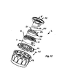
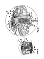
- the installation element 1 according to the FIGS. 1 to 6 has the jet regulator 11, which has here designed as a perforated plate 12 and at the same time serving as a control element 9 beam splitter 12.
- the jet splitter 12 has two coaxial hole circles 13 with flow holes.
- a wheel-shaped adjusting element 10 is displaceable in the longitudinal direction, but rotatably guided.
- the actuator 10 is between an open position and an in FIG. 3 shown closed position movable. In the closed position according to FIG.
- FIG. 3 is the wheel-shaped actuator 10 with a portion 16a of its central "wheel hub" on the inner hole circle 13 of the designed as a control element Strahlzerlegers 12 that this inner hole circle 13 is sealed and only the outer hole circle 13 remains open.
- a threaded opening 16 is provided, into which a threaded pin 17 engages.
- the threaded pin 17 protrudes on the outflow side of the control element 8 designed as an attachment or filter screen 14 such that a rotational movement on the control element 8 can be converted into a longitudinal movement of the control element 10.
- the adjusting device is designed as an adjustable flow rate regulator 18, which has to regulate the per unit of time flowing through water to a preselectable constant value.
- flow regulator 18 Serving as an adjusting device flow regulator 18 has an annular throttle body 19 made of elastic material which defines a control gap 22 between itself and one, provided on an adjacent peripheral wall 20 control profile 22, which control gap 22 in its clear flow cross-section by means of the pressure of the fluid flowing through deforming throttle body 19 is variable.
- the peripheral wall 20 narrow or widen in its longitudinal direction in the longitudinal direction at least in its partial region having the regular profiling 21 and / or the regular profiling 21 itself.
- a support 23 intended to rest on the throttle body 19 is designed as an adjusting element 10 which is adjustable in the longitudinal direction, while the peripheral wall 20 having the control profile 21 is provided as a control element 9.
- the circumferential wall 20 is provided as an adjusting element 10, which adjusting element 10 is displaceably guided in the longitudinal direction relative to the support body which carries the throttle body 19 and is designed as a control element 9.
- the adjusting device designed as a flow rate regulator 18 is located on the Inflow side of the jet regulator 11 or the like fixture releasably held.
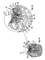
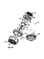
- the installation element 2 according to the FIGS. 7 to 12 has a serving as a control element 8 intent or filter screen 14, at the downstream side of a mushroom or T-shaped support pin or the like support 23 is integrally formed and protrudes in the axial direction.
- a serving as a control element 9 support 23 is encompassed by a profile ring 25, the inner peripheral wall 20 is provided as an adjusting element 10 and carries the control profile 21.
- an internal thread 27 is provided, in which engage on the outer circumference of the profile ring 25 projecting guide pin 28 or the like projections.
- the profile ring 25 is so longitudinally adjustable with the designed as a header or filter 14 control element 8 in the longitudinal direction, but non-rotatably connected, that a rotational movement on the control element 8 by means provided on the housing 26 internal thread 27 in a longitudinal movement of the profile ring 25 and thus in a relative movement between the provided on the inner peripheral wall 20 of the profile ring 25 rule profiling 21 and the throttle body 19 can be implemented.
- the housing 26 of the adjusting device can be releasably latched on the jet splitter 12 of the jet regulator 11, which is designed as a perforated plate.
- the jet splitter 12 is one of the components of the downstream in the flow direction jet regulator 11.
- the jet regulator 11 has in its jet regulator housing 29 on other structures that form the water flowing through in the desired manner.
- the housing 26 is the flow regulator 18 configured adjusting device also on the jet splitter 12 of downstream in the flow direction jet regulator 11 releasably secured.
- the housing 26 of the actuating device has on the inner circumference of the housing a plurality of ramps 30 evenly spaced over the circumference of the housing and stepped here, on which a profile ring 31 rests.
- the profile ring 31 has on its, serving as an actuator 10 inner peripheral wall 20, the Regelprofil ist 21.
- the housing 26 of the setting device is configured cup-shaped.
- the flange laterally projecting housing edge 34 of the housing 26 is rotatably supported on the inflow side of the downstream in the flow direction jet regulator 11 and preferably releasably latched.
- the pot bottom of the cup-shaped housing 26 is serving as the intentionally also as a control element 8 intent or filter screen 14 designed.
- a disc-shaped support 23 is provided for the throttle body 19, which has at its outer disc edge a plurality of distributed over the disc circumference arranged sliding peg 28 or the like sliders that protrude into the helical groove 35 such that a rotational movement on the control element 8 in a sliding movement of serving as an actuator 10 support 23 can be implemented.
- the support 23 is displaceable in the housing 26, but rotatably guided.
- the support 23 is designed to spokes wheel-shaped, the spokes 37 of this wheel shape engage in longitudinal grooves 38 which carries a profile ring 39.
- This profile ring 39 which is releasably latched to the jet splitter 12 of the downstream jet regulator 11, has the serving as a control element 9 peripheral wall, which carries the control profile 21.
- the adjusting device upstream of the jet regulator 11 is designed as a flow rate regulator 18.
- the throttle body 19 made of elastic material rests on a support 23 which is displaceably guided in the installation element 5 in the longitudinal direction.
- a threaded pin 40 is integrally formed with internal thread.
- the threaded pin 40 connected to the support 23 is displaceably guided in a guide sleeve 41 in the longitudinal direction of the adjusting device, which guide sleeve 41 is provided centrally on the jet splitter 12 of the jet regulator 11.
- an operating element 8 is screwed.
- the here helically configured control element 8 is such with the head 43 of its helical form clamped between the free end region of the guide sleeve 41 and the outflow side of the mounting element 5 and designed here with honeycomb flow passages configured flow rectifier 44, that with a portion of a handling opening 45 passing through the flow straightener 44 projecting control element 8 rotatable but immovable in the longitudinal direction in the mounting element 5 is stored.
- a rotational movement on the operating element 8 is transmitted via the external thread on the threaded portion 42 and the internal thread of the threaded pin 40 on serving as an actuator 10 supports 23 that the resting thereon throttle body 19 are moved relative to the serving as a control element inner peripheral wall 20 in the axial direction can.
- the support 23 of the installation element 5 associated adjusting device is configured spokes wheel, the wheel spokes 46 of Speichenradform in guide grooves 47 of the control profile 21 supporting mecanicswandung 20 are guided such that the actuator 10 is displaced by a rotational movement on the control element 8 in the longitudinal direction, but can not be twisted.
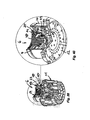
- the mounting element 6 also has an adjusting device designed as a flow rate regulator 18.
- a front or filter screen 14 is rotatably mounted, which also serves as a control element 8 of the adjusting device.
- a threaded pin 48 is integrally formed.
- an annular bearing 23 is screwed with an internal thread.
- the bearing for the throttle body 19 and serving as an actuator 10 support 23 has on the outer circumference of its annular shape projecting guide pin 49 which in guide grooves 50 of the housing 26 of the actuating device intervene such that the support 23 rotatably, but guided in the longitudinal direction displaceable in the housing 26.
- the housing 26 is detachably held on the jet separator 12 provided as a perforated plate of the jet regulator 11 provided downstream.
- the applied via the control element 8 on the threaded pin 48 rotational movement is converted into a longitudinal movement of serving as an actuator 10 Auflagers 23.
- the configured as a flow regulator 18 actuating device of the mounting element 7 according to the Figures 42 to 48 has a housing 26 which carries an internal thread 51 at its inner housing circumference.
- At the inflow-side end edge region of the housing 26 rotatably mounted and designed here as intent or filter 14 control element 8 are in the longitudinal direction of the actuator oriented drive pin 53, which engage in coupling openings 54 on the inflow-side end edge of the annular support 23 displaceable, but rotationally fixed.
- a rotational movement on the operating element 8 is transmitted to the support 23 in such a way that the support 23 can slide along the internal thread 51 of the housing 26 in the longitudinal direction of the actuating device. Due to the longitudinal movement of the support 23 and the throttle body 19 thereon, the relative position can be change between the throttle body 19 and a control profile 21, which is integrally formed on the outer circumference 56 of the control element 8, in the axial direction to the free end tapered and serving as a control element 9 control core 55 is provided.
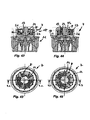
- a rotational position indicator 79 may be provided for identifying the selected rotational position of the actuating element 10.
- this rotary position indicator on a display opening 81 on the attachment screen 14, which cooperates with codes, codes or the like characteristics, which are provided on the adjacent end face of the jet regulator housing.
Description
Die Erfindung betrifft ein sanitäres Einbauelement, das in dem Wasserauslauf einer sanitären Auslaufarmatur einsetzbar ist und eine Stelleinrichtung zum Verändern des lichten Durchflussquerschnitts des Einbauelements und/oder des Volumenstroms hat, welche Stelleinrichtung über wenigstens ein Bedienelement betätigbar ist, das an der Zuströmseite des Einbauelements und/oder an dessen Abströmseite betätigbar angeordnet ist, wobei die Stelleinrichtung ein Regelelement und ein damit zusammenwirkendes Stellelement hat, deren Relativposition zum Verändern des Durchflussquerschnitts oder der Durchflussleistung mittels dem wenigstens einen Bedienelement veränderbar ist.The invention relates to a sanitary installation element which can be inserted in the water outlet of a sanitary outlet fitting and has an adjusting device for changing the clear flow cross section of the installation element and / or the volume flow, which adjusting device can be actuated via at least one operating element which is located on the inflow side of the installation element and / or. or is arranged operably on the downstream side thereof, wherein the adjusting device has a control element and a control element cooperating therewith, whose relative position for changing the flow cross-section or the flow rate by means of the at least one control element is variable.
Man kennt bereits verschiedene sanitäre Einbauelemente, die am Wasserauslauf einer sanitären Auslaufarmatur montiert werden können, um dort den austretenden Wasserstrahl zu regeln oder zu formen. So hat man bereits verschiedene Strahlregler geschaffen, die den aus dem Wasserauslauf einer sanitären Auslaufarmatur austretenden Wasserstrahl zu einem homogenen, nicht-spritzenden und gegebenenfalls auch perlend-weichen Gesamtstrahl formen sollen.Various sanitary installation elements are already known which can be mounted on the water outlet of a sanitary outlet fitting in order to regulate or form the outgoing water jet there. So you have already created various aerators that are designed to form the emerging from the water outlet of a sanitary outlet fitting water jet to a homogeneous, non-splashing and possibly also pearly-soft overall jet.
Aus der
Aus der
Da in den verschiedenen Ländern unterschiedliche Spezifikationen im sanitären Wassersystem vorzufinden sind, ist eine entsprechende Vielzahl von Strahlreglern erforderlich, um den landestypischen Spezifikationen gerecht zu werden. Die Vielzahl von Strahlreglern erfordert einen nicht unerheblichen Herstellungs- und Bevorratungsaufwand. Da die von verschiedenen Herstellern angebotenen Auslaufarmaturen einen unterschiedlichen und teils auch hohen hydraulischen Widerstand leisten, werden zum Einregeln der pro Zeiteinheit maximal austretenden Wassermenge unterschiedliche Durchflussmengenregler erforderlich, wodurch der Herstellungs- und Bevorratungsaufwand noch zusätzlich erhöht ist.As there are different specifications in the sanitary water system in the different countries, a corresponding large number of jet regulators is required to meet the country-specific specifications. The variety of beam regulators requires a considerable manufacturing and storage costs. Since the discontinuation valves offered by various manufacturers provide a different and sometimes also high hydraulic resistance, different flow rate regulators are required for adjusting the maximum amount of water per unit time, whereby the manufacturing and storage costs are increased even further.
Es besteht daher insbesondere die Aufgabe, ein zur Reduzierung des Herstellungs- und Bevorratungsaufwands bestimmtes und zur Anpassung an die individuellen Wünsche des betreffenden Anwenders und/oder an die spezifischen sanitären Umgebungsbedingungen möglichst vielseitig einsetzbares sanitäres Einbauelement der eingangs erwähnten Art zu schaffen, das eine Alternativlösung zum Betätigen des Regelelements beinhaltet.It is therefore the object in particular to provide a sanitary installation element of the type mentioned at the outset which is intended to reduce the production and storage costs and which is as versatile as possible to adapt to the individual wishes of the user concerned and / or to the specific sanitary environment conditions Actuation of the control element includes.
Die erfindungsgemäße Lösung dieser Aufgabe besteht bei dem sanitären Einbauelement der eingangs erwähnten Art insbesondere darin, dass das wenigstens eine Bedienelement drehbar, aber in Längsrichtung des Einbauelements unverrückbar gelagert ist, dass das Stellelement in Längsrichtung verschieblich und drehfest geführt ist, und dass eine Drehbewegung an diesem Bedienelement in eine Längsbewegung des Stellelementes umsetzbar ist.The inventive solution to this problem is in the sanitary installation element of the type mentioned in particular that the at least one control rotatable, but is immovably mounted in the longitudinal direction of the mounting element, that the adjusting element is guided displaceably in the longitudinal direction and rotationally fixed, and that a rotational movement of this operating element in a longitudinal movement of the actuating element can be implemented.
Das erfindungsgemäße Einbauelement, das in den Wasserauslauf einer sanitären Auslaufarmatur einsetzbar und dort lösbar gehalten ist, weist eine Stelleinrichtung auf, die zum Verändern des lichten Durchflussquerschnitts des Einbauelements und/oder der Durchflussleistung bestimmt ist. Die Stelleinrichtung des erfindungsgemäßen Einbauelements ist über wenigstens ein Bedienelement betätigbar, das an der Zuströmseite des Einbauelements und/oder an dessen Abströmseite betätigbar angeordnet ist. Die Stelleinrichtung hat ein Regelelement und ein damit zusammenwirkendes Stellelement, deren Relativposition zum Verändern des Durchflussquerschnitts oder der Durchflussleistung mittels dem wenigstens einen Bedienelement veränderbar ist. Während wenigstens ein Bedienelement drehbar, aber in Längsrichtung unverrückbar gelagert ist, ist das damit zusammenwirkende Stellelement in Längsrichtung verschieblich und drehfest geführt, derart, dass eine Drehbewegung an dem Bedienelement in eine Längsbewegung des Stellelements umsetzbar ist. Durch Betätigen der Stelleinrichtung an dem, an der Zuström- oder Abströmseite des Einbauelements angeordneten Bedienelement, kann der lichte Durchflussquerschnitt und/oder die pro Zeiteinheit maximal austretende Wassermenge derart verändert werden, dass das erfindungsgemäße Einbauelement den unterschiedlichen lokalen Vorbedingungen im Leitungsnetz gerecht wird. Da ein und dasselbe Einbauelement an die Spezifikationen der in verschiedenen Ländern vorzufindenden Wassernetze angepasst werden kann, ist die Herstellung und Bevorratung verschiedener Strahlreglerausführungen nicht mehr zwingend erforderlich.The installation element according to the invention, which is used in the water outlet of a sanitary outlet fitting and kept detachable there, has an adjusting device which is intended for changing the clear flow cross section of the installation element and / or the flow rate. The adjusting device of the installation element according to the invention can be actuated via at least one operating element which is arranged to be actuated on the inflow side of the installation element and / or on its outflow side. The adjusting device has a control element and a control element cooperating therewith, whose relative position for changing the flow cross-section or the flow rate by means of the at least one control element is variable. While at least one control element is rotatable but non-displaceably mounted in the longitudinal direction, the co-operating control element is displaceable in the longitudinal direction and rotatably guided, such that a rotational movement on the operating element in a longitudinal movement of the actuating element can be implemented. By operating the adjusting device on the, on the inflow or outflow side of the mounting element arranged operating element, the clear flow cross-section and / or the maximum per unit time exiting water quantity can be changed so that the installation element of the invention is the different local preconditions in the pipe network fair. Since one and the same installation element can be adapted to the specifications of the water networks to be found in different countries, the production and storage of various jet regulator designs is no longer absolutely necessary.
Um eine kontrollierte und/oder wiederholbare Stellbewegung zu erreichen, ist es zweckmäßig, wenn das Stellelement in Längsrichtung der Stelleinrichtung beweglich geführt ist.In order to achieve a controlled and / or repeatable adjusting movement, it is expedient if the adjusting element is guided movably in the longitudinal direction of the adjusting device.
Die Drehbewegung am Bedienelement lässt sich besonders einfach in eine Längsbewegung des Stellelements umsetzen, wenn an wenigstens einem Bedienelement ein vorzugsweise koaxial zur Stelleinrichtung angeordneter Gewindezapfen vorsteht, der in eine Gewindeöffnung im Stellelement eingreift.The rotational movement on the operating element can be converted into a longitudinal movement of the adjusting element particularly easily if at least one operating element projects a threaded pin, which is preferably arranged coaxially with respect to the adjusting device and engages in a threaded opening in the adjusting element.
Die vorbekannten Einbauelemente weisen regelmäßig ein zuströmseitiges Filter- oder Vorsatzsieb auf, das im Wasser unbeabsichtigt mitgeführte Schmutzpartikel zurückhalten und das Einbauelement vor verschmutzungsbedingten Verstopfungen bewahren soll.The previously known installation elements regularly have an inflow-side filter or attachment screen, which is intended to withhold inadvertently entrained dirt particles in the water and to protect the installation element from contamination-related blockages.
Eine bevorzugte Weiterbildung von eigener schutzwürdiger Bedeutung sieht vor, dass die Stelleinrichtung als Durchflussmengenregler ausgebildet ist, der einen ringförmigen Drosselkörper aus elastischem Material hat, welcher zwischen sich und einer an einer benachbarten Innen- und/oder Außenumfangswandung vorgesehenen Regelprofilierung einen Steuerspalt begrenzt, welcher Steuerspalt in seinem lichten Durchflussquerschnitt mittels dem unter dem Druck des durchdringenden Fluids verformenden Drosselkörper veränderbar ist. Eine solche, als einstellbarer Durchflussmengenregler ausgestaltete Stelleinrichtung erlaubt es, das sanitäre Einbauelement auf eine Durchflussleistung einzustellen, die den am Einsatzort vorgefundenen Spezifikationen des Wassernetzes entspricht.A preferred development of its own meaning worthy of protection provides that the adjusting device is designed as a flow regulator, which has an annular throttle body made of elastic material, which defines a control gap between itself and one provided on an adjacent inner and / or outer peripheral wall control profile, which control gap in its clear flow cross section is variable by means of deforming under the pressure of the penetrating fluid throttle body. Such, configured as an adjustable flow regulator actuator allows you to set the sanitary installation element to a flow rate that corresponds to the found at the site specifications of the water network.
Um mit Hilfe einer solchen, als Durchflussmengenregler ausgebildeten Stelleinrichtung verschiedene vorwählbare Durchflussleistungen realisieren zu können, ist es vorteilhaft, wenn die Innen- und/oder die Außenumfangswandung zumindest in ihrem die Regelprofilierung aufweisen Teilbereich und/oder die Regelprofilierung sich in ihrem lichten Querschnitt in Längsrichtung erweitern.In order to be able to realize various preselectable flow rates with the aid of such an adjusting device designed as a flow rate regulator, it is advantageous if the inner and / or the outer circumferential wall expand in their longitudinal direction in their clear cross section, at least in their part profiling and / or the control profiling ,
Zweckmäßig ist es, wenn ein zur Auflage für den Drosselkörper bestimmtes Auflager oder die die Regelprofilierung aufweisende Innen- und/oder Außenumfangswandung als Stellelement ausgestaltet ist, welches mit der als Regelelement ausgebildeten Innen- und/oder Außenumfangswandung oder dem Auflager zusammenwirkt. Während ein Ausführungsbeispiel vorsieht, dass das zur Auflage für den Drosselkörper bestimmte Auflager als Stellelement und die Innen- und/oder Außenumfangswandung als Regelelement ausgestaltet ist, besteht ein anderes Ausführungsbeispiel darin, dass demgegenüber die Innen- und/oder Außenumfangswandung als Stellelement und das zum Auflegen des Drosselkörpers vorgesehene Auflager als Regelelement dienen.It is expedient if a support which is intended to rest for the throttle body or the inner and / or outer peripheral wall having the control profiling is designed as an actuating element which is designed with the control element Inner and / or Außenumfangswandung or the support cooperates. While an embodiment provides that the bearing for the throttle body certain bearing is designed as an actuator and the inner and / or Außenumfangswandung as a control element, another embodiment is that in contrast, the inner and / or Außenumfangswandung as an actuating element and for laying the throttle body provided supports serve as a control element.
Die vielseitige Anwendbarkeit des erfindungsgemäßen Einbauelements wird begünstigt, wenn die Stelleinrichtung auf der Zuströmseite eines Strahlreglers oder dergleichen sanitären Einbauteiles lösbar befestigbar ist. Ein solches Einbauelement, bei dem die Stelleinrichtung lösbar am Strahlregler oder dergleichen befestigt ist, kann wahlweise entweder mit oder ohne die Stelleinrichtung betrieben werden.The versatility of the installation element according to the invention is favored when the adjusting device on the upstream side of a jet regulator or the like sanitary fixture is releasably fastened. Such a mounting element, in which the actuating device is releasably attached to the jet regulator or the like, can be operated either with or without the adjusting device.
Weitere Merkmale gemäß der Erfindung ergeben sich aus der Beschreibung sowie den Ansprüchen. Nachstehend wird die Erfindung anhand verschiedener Ausführungsbeispiele noch näher beschrieben.Further features according to the invention will become apparent from the description and the claims. The invention will be described in more detail with reference to various embodiments.
Es zeigt:
- Fig. 1
- ein in einer längsgeschnittenen Drehstellung dargestelltes sanitäres Einbauelement, das einen abströmseitigen Strahlregler mit einem als Lochplatte ausgebildeten Strahlzerleger umfasst, wobei die in der als Strahlzerleger dienenden Lochplatte vorgesehenen Durchflusslöcher in konzentrischen Lochkreisen angeordnet sind, von denen sich zumindest ein Lochkreis oder - hier nicht dargestellt wenigstens ein Teil zumindest eines Lochkreises - mittels eines in Längsrichtung der Stelleinrichtung verschieblichen Stellelements öffnen und verschließen lässt,
- Fig. 2
- das in der Drehstellung gemäß
Figur 1 - Fig. 3
- das längsgeschnittene Einbauelement aus
Figur 1 und 2 - Fig. 4
- das in der Drehstellung gemäß
Figur 3 - Fig. 5
- das Einbauelement aus den
Figuren 1 bis 4 - Fig. 6
- das Einbauelement aus den
Figuren 1 bis 5 - Fig. 7
- ein in einer längsgeschnittenen Drehstellung dargestelltes sanitäres Einbauelement, das einen abströmseitigen Strahlregler umfasst, dem auf der Zuströmseite eine als Durchflussmengenregler ausgebildete Stelleinrichtung vorgeschaltet ist, wobei der als Stelleinrichtung dienende Durchflussmengenregler einen in Längsrichtung verschieblich geführten Profilring hat, der mit einem ringförmigen Drosselkörper aus elastischem Material zusammenwirkt,
- Fig. 8
- das in der Drehstellung gemäß
Figur 7 - Fig. 9
- das längsgeschnittene Einbauelement aus
Figur 7 und 8 - Fig. 10
- das in der Drehstellung gemäß
Figur 9 - Fig. 11
- das Einbauelement aus den
Figuren 7 bis 10 - Fig. 12
- das Einbauelement aus den
Figuren 7 bis 11 - Fig. 13
- ein in einer längsgeschnittenen Drehstellung dargestelltes sanitäres Einbauelement mit einer ebenfalls als Durchflussmengenregler ausgebildeten Stelleinrichtung, wobei am Gehäuseinnenumfang der Stelleinrichtung Rampen vorgesehen sind, auf denen ein Regelprofilierungen aufweisender Profilring in Längsrichtung verschieblich aufliegt,
- Fig. 14
- das in der Drehstellung gemäß
Figur 13 - Fig. 15
- das längsgeschnittene Einbauelement aus
Figur 13 und 14 in einer demgegenüber anderen Stellposition, - Fig. 16
- das in einer perspektivischen Draufsicht gezeigte Gehäuse des in
den Figuren 13 bis 15 dargestellten Einbauelements, wobei am Gehäuseinnenumfang die Rampen der Stelleinrichtung deutlich zu erkennen sind, - Fig. 17
- das in der Drehstellung gemäß
Figur 15 gezeigte Einbauelement in einer Draufsicht auf seine Zuströmseite, - Fig. 18
- das Einbauelement
aus den Figuren 13 in einem entgegen der Durchströmrichtung orientierten perspektivischen Teil-Längsschnitt,bis 17 - Fig. 19
- das Einbauelement
aus den Figuren 13 in einem vergrößert dargestellten Detail-bis 18Längsschnitt aus Figur 18, - Fig. 20
- das Einbauelement
aus den Figuren 13 in einer auseinandergezogenen Perspektivansicht seiner Einzelteile,bis 19 - Fig. 21
- ein in einer längsgeschnittenen Drehstellung dargestelltes sanitäres Einbauelement mit einer zuströmseitigen Stelleinrichtung, bei der das Gehäuse der Stelleinrichtung derart drehbar an der Zuströmseite eines Strahlreglers gehalten ist, dass eine Drehbewegung des Gehäuses in eine Längsbewegung des zur Auflage des Drosselkörpers bestimmten Auflagers umgesetzt werden kann,
- Fig. 22
- das in der Drehstellung gemäß
Figur 21 gezeigte Einbauelement in einer Draufsicht auf seine Zuströmseite, - Fig. 23
- das längsgeschnittene Einbauelement aus
den Figuren 21 und 22 in einer demgegenüber anderen Stellposition, - Fig. 24
- das in der Drehstellung gemäß
Figur 23 gezeigte Einbauelement in einer Draufsicht auf seine Zuströmseite, - Fig. 25
- das Einbauelement
aus den Figuren 21 in einem perspektivischen Teil-Längsschnitt,bis 24 - Fig. 26
- das Einbauelement
aus den Figuren 21 in einem vergrößert dargestellten Detail-bis 25Längsschnitt aus Figur 25, - Fig. 27
- das Einbauelement
aus den Figuren 21 in einer auseinandergezogenen Perspektivdarstellung seiner Einzelteile,bis 26 - Fig. 28
- ein in einer längsgeschnittenen Drehstellung dargestelltes sanitäres Einbauelement mit einer Stelleinrichtung, die über ein hier abströmseitig vorgesehenes Bedienelement betätigt werden kann,
- Fig. 29
- das in der Drehstellung gemäß
Figur 28 gezeigte Einbauelement in einer Draufsicht auf seine Zuströmseite, - Fig. 30
- das längsgeschnittene Einbauelement aus
Figur 28 und 29 in einer demgegenüber anderen Stellposition, - Fig. 31
- das in der Drehstellung gemäß
Figur 30 gezeigte Einbauelement in einer Draufsicht auf seine Zuströmseite, - Fig. 32
- das Einbauelement
aus den Figuren 28 in einem perspektivischen Teil-Längsschnitt,bis 31 - Fig. 33
- das Einbauelement
aus den Figuren 28 in einem vergrößert dargestellten Detail-bis 32Längsschnitt aus Figur 32, - Fig. 34
- das Einbauelement
aus den Figuren 28 in einer auseinandergezogenen und entgegen der Durchströmrichtung orientierten Perspektivdarstellung seiner Einzelteile,bis 33 - Fig. 35
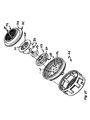
- ein in einer längsgeschnittenen Drehstellung dargestelltes sanitäres Einbauelement mit einer zuströmseitigen Stelleinrichtung, die als Durchflussmengenregler ausgestaltet ist, wobei das für den ringförmigen Drosselkörper vorgesehene Auflager im Gehäuseinneren der Stelleinrichtung in Längsrichtung verschieblich geführt ist,
- Fig. 36
- das in der Drehstellung gemäß
Figur 35 gezeigte Einbauelement in einer Draufsicht auf seine Zuströmseite, - Fig. 37
- das längsgeschnittene Einbauelement aus
Figur 35 und 36 in einer demgegenüber anderen Stellposition, - Fig. 38
- das in der Drehstellung gemäß
Figur 37 gezeigte Einbauelement in einer Draufsicht auf seine Zuströmseite, - Fig. 39
- das
Einbauelement aus Figur 35 bis 38 in einem perspektivischen Teil-Längsschnitt, - Fig. 40
- das Einbauelement
aus den Figuren 35 in einem vergrößert dargestellten Detail-bis 39Längsschnitt aus Figur 39, - Fig. 41
- das Einbauelement
aus den Figuren 35 in einer auseinandergezogenen und entgegen der Zuströmrichtung orientierten Perspektivdarstellung seiner Einzelteile,bis 40 - Fig. 42
- ein in einer längsgeschnittenen Drehstellung dargestelltes sanitäres Einbauelement, das an der Zuströmseite eine ebenfalls als Durchflussmengenregler ausgestaltete Stelleinrichtung hat, wobei am Gehäuseinnenumfang der Stelleinrichtung Gleitvorsprünge eingreifen, die am Außenumfang eines ringförmigen Auflagers für den Drosselkörper vorgesehen sind,
- Fig. 43
- das in der Drehstellung gemäß
Figur 42 gezeigte Einbauelement in einer Draufsicht auf seine Zuströmseite, - Fig. 44
- das längsgeschnittene Einbauelement aus
Figur 42 und 43 in einer demgegenüber anderen Stellposition, - Fig. 45
- das in der Drehstellung gemäß
Figur 44 gezeigte Einbauelement in einer Draufsicht auf seine Zuströmseite, - Fig. 46
- das Einbauelement
aus den Figuren 42 in einem perspektivischen Teil-Längsschnitt,bis 45 - Fig. 47
- das Einbauelement
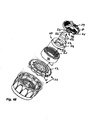
aus den Figuren 42 in einem vergrößert dargestellten Detail-bis 46Längsschnitt aus Figur 46 , und - Fig. 48
- das Einbauelement
aus den Figuren 42 in einer auseinandergezogenen Perspektivdarstellung seiner Einzelteile.bis 47
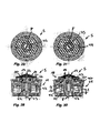
- Fig. 1
- a in a longitudinally rotated position shown sanitary installation element comprising a downstream jet regulator with a perforated plate designed as a jet splitter, wherein the flow holes provided in the perforated plate serving as flow holes are arranged in concentric hole circles, of which at least one bolt circle or - not shown here at least one Part of at least one bolt circle - by means of a longitudinal direction the adjusting device slidable actuator can open and close,
- Fig. 2
- in accordance with the rotational position
FIG. 1 shown installation element in a plan view of its inflow side, - Fig. 3
- the longitudinally cut mounting element
FIGS. 1 and 2 in a different position, in contrast, - Fig. 4
- in accordance with the rotational position
FIG. 3 shown installation element in a plan view of its inflow side, - Fig. 5
- the installation element of the
FIGS. 1 to 4 in a perspective partial longitudinal section, - Fig. 6
- the installation element of the
FIGS. 1 to 5 in an exploded and counter to the flow direction oriented representation of its individual parts, - Fig. 7
- a shown in a longitudinally rotated position sanitary installation element comprising a downstream jet regulator, which is preceded on the inlet side designed as a flow regulator adjusting device, wherein the adjusting device serving as a flow regulator has a longitudinally displaceably guided profile ring which cooperates with an annular throttle body made of elastic material .
- Fig. 8
- in accordance with the rotational position
FIG. 7 shown installation element in a plan view of its inflow side, - Fig. 9
- the longitudinally cut mounting element
FIGS. 7 and 8 in a different position, in contrast, - Fig. 10
- in accordance with the rotational position
FIG. 9 shown installation element in a plan view of its inflow side, - Fig. 11
- the installation element of the
FIGS. 7 to 10 in a perspective partial longitudinal section, - Fig. 12
- the installation element of the
FIGS. 7 to 11 in an exploded and in a side perspective view shown of its individual parts, - Fig. 13
- a in a longitudinally rotated position shown sanitary installation element with a likewise designed as a flow regulator adjusting device, wherein ramps are provided on the housing inner circumference of the actuating device on which a profile sections profiled ring in the longitudinal direction slidably rests
- Fig. 14
- in accordance with the rotational position
FIG. 13 shown installation element in a plan view of its inflow side, - Fig. 15
- the longitudinally cut mounting element
FIGS. 13 and 14 in a different position, in contrast, - Fig. 16
- the shown in a perspective plan view of the housing in the
FIGS. 13 to 15 illustrated installation element, wherein the ramps of the adjusting device can be clearly seen on the housing inner circumference, - Fig. 17
- in accordance with the rotational position
FIG. 15 shown installation element in a plan view of its inflow side, - Fig. 18
- the installation element of the
FIGS. 13 to 17 in a direction opposite to the flow oriented perspective part longitudinal section, - Fig. 19
- the installation element of the
FIGS. 13 to 18 in an enlarged detail longitudinal section of FIG. 18, - Fig. 20
- the installation element of the
FIGS. 13 to 19 in an exploded perspective view of its parts, - Fig. 21
- a in a longitudinally rotated position shown sanitary installation element with an inflow-side adjusting device, wherein the housing of the adjusting device is rotatably supported on the upstream side of a jet regulator, that a rotational movement of the housing can be converted into a longitudinal movement of the particular bearing for the throttle body support,
- Fig. 22
- in accordance with the rotational position
FIG. 21 shown installation element in a plan view of its inflow side, - Fig. 23
- the longitudinally cut mounting element of the
FIGS. 21 and 22 in a different position, in contrast, - Fig. 24
- in accordance with the rotational position
FIG. 23 shown installation element in a plan view of its inflow side, - Fig. 25
- the installation element of the
FIGS. 21 to 24 in a perspective partial longitudinal section, - Fig. 26
- the installation element of the
FIGS. 21 to 25 in an enlarged detail longitudinal section from FIG. 25, - Fig. 27
- the installation element of the
FIGS. 21 to 26 in an exploded perspective view of its individual parts, - Fig. 28
- a sanitary installation element shown in a longitudinally cut rotary position with an adjusting device which can be actuated via an operating element provided downstream therefrom,
- Fig. 29
- in accordance with the rotational position
FIG. 28 shown installation element in a plan view of its inflow side, - Fig. 30
- the longitudinally cut mounting element
FIGS. 28 and 29 in a different position, in contrast, - Fig. 31
- in accordance with the rotational position
FIG. 30 shown installation element in a plan view on its inflow side, - Fig. 32
- the installation element of the
FIGS. 28 to 31 in a perspective partial longitudinal section, - Fig. 33
- the installation element of the
FIGS. 28 to 32 in an enlarged detail longitudinal section of FIG. 32, - Fig. 34
- the installation element of the
FIGS. 28 to 33 in an exploded and counter to the flow oriented perspective view of its individual parts, - Fig. 35
- a sanitary installation element shown in a longitudinally cut rotary position with an inlet-side adjusting device which is designed as a flow rate regulator, wherein the support provided for the annular throttle body is displaceably guided longitudinally in the housing interior of the adjusting device,
- Fig. 36
- in accordance with the rotational position
FIG. 35 shown installation element in a plan view of its inflow side, - Fig. 37
- the longitudinally cut mounting element
FIGS. 35 and 36 in a different position, in contrast, - Fig. 38
- in accordance with the rotational position
FIG. 37 shown installation element in a plan view of its inflow side, - Fig. 39
- the built-in element
FIGS. 35 to 38 in a perspective partial longitudinal section, - Fig. 40
- the installation element of the
FIGS. 35 to 39 in an enlarged detail longitudinal section from FIG. 39, - Fig. 41
- the installation element of the
FIGS. 35 to 40 in an exploded and counter to the inflow direction oriented perspective view of its individual parts, - Fig. 42
- a sanitary installation element which is shown in a longitudinally cut rotary position and has on the inflow side an adjusting device which is likewise designed as a flow rate regulator, sliding projections on the housing inner circumference of the actuating device being provided on the outer circumference of an annular support for the throttle body,
- Fig. 43
- in accordance with the rotational position
Figure 42 shown installation element in a plan view of its inflow side, - Fig. 44
- the longitudinally cut mounting element
FIGS. 42 and 43 in a different position, in contrast, - Fig. 45
- in accordance with the rotational position
FIG. 44 shown installation element in a plan view of its inflow side, - Fig. 46
- the installation element of the
Figures 42 to 45 in one perspective partial longitudinal section, - Fig. 47
- the installation element of the
FIGS. 42 to 46 in an enlarged detail longitudinal section shownFIG. 46 , and - Fig. 48
- the installation element of the
Figures 42 to 47 in an exploded perspective view of its individual parts.
In den
Durch Betätigen der Stelleinrichtung an dem Bedienelement 8 kann der lichte Durchflussquerschnitt und/oder die pro Zeiteinheit austretende Wassermenge, die im Folgenden als Volumenstrom definiert ist, derart verändert werden, dass die Einbauelemente 1, 2, 3, 4, 5, 6 und 7 den unterschiedlichen Vorbedingungen diverser Leitungsnetze gerecht werden. Da ein und dasselbe Einbauelement 1, 2, 3, 4, 5, 6 und 7 an die Spezifikationen der in verschiedenen Ländern vorzufindenden Wassernetze angepasst werden kann, ist die Herstellung und Bevorratung verschiedener Ausführungen nicht mehr zwingend erforderlich.By actuating the adjusting device on the
Die Stelleinrichtung der Einbauelemente 1, 2, 3, 4, 5, 6 und 7 weist ein Regelelement 9 und ein damit zusammenwirkendes Stellelement 10 auf, deren Relativposition zum Verändern des Durchflussquerschnitts oder des Volumenstroms mittels dem wenigstens einen Bedienelement 8 veränderbar ist. Das drehbar gelagerte Bedienelement 8 steht mit der Stelleinrichtung derart in Antriebsverbindung, dass eine Drehbewegung am Bedienelement 8 in eine Längsbewegung des in Längsrichtung der Stelleinrichtung beweglich geführten Stellelements 10 umsetzbar ist.The adjusting device of the mounting
Die Einbauelemente 1, 2, 3, 4, 5, 6 und 7 weisen hier einen Strahlregler 11 auf, der einen homogenen, nicht-spritzenden und gegebenenfalls auch perlend-weichen Wasserstrahl formen soll. Der Strahlregler 11 der Einbauelemente 1, 2, 3, 4, 5, 6 und 7 weist einen Strahlzerleger 12 auf, der das durchströmende Wasser vorübergehend in eine Vielzahl von Einzelstrahlen aufzuteilen hat. Der Strahlzerleger 12 ist dazu als Lochplatte ausgebildet, die eine Vielzahl von Durchflusslöchern hat. Die am Strahlzerleger vorgesehenen Durchflusslöcher sind in zumindest einem Lochkreis 13 und gegebenenfalls in mehreren koaxialen Lochkreisen 13 angeordnet (vgl.
Die Einbauelemente 1, 2, 3, 4, 5, 6 und 7 weisen ein zuströmseitiges Vorsatz- oder Filtersieb 14 auf, das die im anströmenden Wasser eventuell mitgeführten Schmutzpartikel auszufiltern hat. Bei den Einbauelementen 1, 2, 3, 4, 6 und 7 ist das im Inneren des Wasserauslaufs gegen unberechtigte oder versehentliche Manipulationen gesichert untergebrachte Vorsatz- oder Filtersieb 14 als in Längsrichtung gehaltenes, aber dennoch drehbar gelagertes Bedienelement 8 ausgebildet.The mounting
Das Einbauelement 1 gemäß den
Bei den Einbauelementen 2 bis 7 ist die Stelleinrichtung als einstellbarer Durchflussmengenregler 18 ausgebildet, der die pro Zeiteinheit durchfließende Wassermenge auf einen vorwählbaren konstanten Wert einzuregeln hat. Der als Stelleinrichtung dienende Durchflussmengenregler 18 weist einen ringförmigen Drosselkörper 19 aus elastischem Material auf, welcher zwischen sich und einer, an einer benachbarten Umfangswandung 20 vorgesehenen Regelprofilierung 21 einen Steuerspalt 22 begrenzt, welcher Steuerspalt 22 in seinem lichten Durchflussquerschnitt mittels dem unter dem Druck des durchströmenden Fluids verformenden Drosselkörper 19 veränderbar ist. Um die Durchflussleistung in dem als Stelleinrichtung dienenden Durchflussmengenregler 18 verändern zu können, ist vorgesehen, dass die Umfangswandung 20 zumindest in ihrem die Regelprofilierung 21 aufweisenden Teilbereich und/oder die Regelprofilierung 21 selbst sich in ihrem lichten Querschnitt in Längsrichtung verengen oder erweitern.In the
Bei den Einbauelementen 4 bis 7 ist ein zur Auflage für den Drosselkörper 19 bestimmtes Auflager 23 als in Längsrichtung verstellbares Stellelement 10 ausgebildet, während die die Regelprofilierung 21 aufweisende Umfangswandung 20 als Regelelement 9 vorgesehen ist.In the case of the installation elements 4 to 7, a
Demgegenüber ist bei den Einbauelementen 2 und 3 die Umfangswandung 20 als Stellelement 10 vorgesehen, welches Stellelement 10 relativ zu dem, den Drosselkörper 19 tragenden und als Regelelement 9 ausgestalteten Auflager 23 in Längsrichtung verschieblich geführt ist.In contrast, in the case of the
Bei den Einbauelementen 2, 3, 4, 6 und 7 ist die als Durchflussmengenregler 18 ausgestaltete Stelleinrichtung auf der Zuströmseite des Strahlreglers 11 oder dergleichen Einbauteils lösbar gehalten.In the case of the
Das Einbauelement 2 gemäß den
Bei dem Einbauelement 3 ist das Gehäuse 26 der als Durchflussmengenregler 18 ausgestalteten Stelleinrichtung ebenfalls auf dem Strahlzerleger 12 des in Strömungsrichtung nachgeschalteten Strahlreglers 11 lösbar befestigt. Das Gehäuse 26 der Stelleinrichtung weist am Gehäuseinnenumfang mehrere über den Gehäuseumfang gleichmäßig beabstandete und hier abgestuft ausgestaltete Rampen 30 auf, auf denen ein Profilring 31 aufsitzt. Der Profilring 31 hat an seiner, als Stellelement 10 dienenden Innenumfangswandung 20 die Regelprofilierung 21. Das als Vorsatz- oder Filtersieb 14 ausgestaltete Bedienelement 8, das am Gehäuse 26 der Stelleinrichtung drehbar gehalten ist, steht mit dem Profilring 31 derart in Antriebsverbindung, dass durch eine Drehbewegung am Bedienelement 8 auch der damit verbundene Profilring 31 auf den Rampen 30 stufenweise fortbewegt und in Längsrichtung derart verschoben werden kann, dass sich die Relativbewegung zwischen der als Stellelement 10 vorgesehenen Innenumfangswandung 20 einerseits und dem den Drosselkörper 19 tragenden Auflager 23 verändert. Dieses Auflager 23 ist zentral in das Gehäuse 26 der Stelleinrichtung eingeformt und vom Profilring 31 umgriffen. Ähnlich wie bei dem Einbauelement 2 stehen an der Abströmseite des Bedienelements 8 Antriebszapfen 32 vor, die derart in entsprechende Kupplungsaussparungen 33 am Profilring 31 eingreifen, dass der Profilring 31 mit dem Bedienelement 8 drehfest, aber relativ verschieblich in Antriebsverbindung steht.In the case of the
Bei dem Einbauelement 4 ist das Gehäuse 26 der Stelleinrichtung topfförmig ausgestaltet. Der flanschartig seitlich vorstehende Gehäuserand 34 des Gehäuses 26 ist auf der Zuströmseite des in Strömungsrichtung nachgeschalteten Strahlreglers 11 drehbar gehalten und vorzugsweise lösbar verrastbar. Der Topfboden des topfförmigen Gehäuses 26 ist als das gleichzeitig auch als Bedienelement 8 dienende Vorsatz- oder Filtersieb 14 ausgestaltet. Am Gehäuseinnenumfang des Gehäuses 26 ist ein Gewinde oder eine Wendelnut 35 vorgesehen. Im Gehäuseinneren des Gehäuses 26 ist ein scheibenförmiges Auflager 23 für den Drosselkörper 19 vorgesehen, das an seinem äußeren Scheibenrand mehrere, über den Scheibenumfang verteilt angeordnete Gleitzapfen 28 oder dergleichen Gleitstücke hat, die in die Wendelnut 35 derart vorstehen, dass eine Drehbewegung am Bedienelement 8 in eine Schiebebewegung des als Stellelement 10 dienenden Auflagers 23 umsetzbar ist. Das Auflager 23 ist im Gehäuse 26 verschieblich, aber drehfest geführt. Das Auflager 23 ist dazu speichenradförmig ausgestaltet, wobei die Speichen 37 dieser Radform in Längsnuten 38 eingreifen, die ein Profilring 39 trägt. Dieser Profilring 39, der am Strahlzerleger 12 des nachgeschalteten Strahlreglers 11 lösbar verrastbar ist, weist die als Regelelement 9 dienende Umfangswandung auf, die die Regelprofilierung 21 trägt.In the case of the installation element 4, the
Bei dem Einbauelement 5 ist die dem Strahlregler 11 vorgeschaltete Stelleinrichtung als Durchflussmengenregler 18 ausgestaltet. Der aus elastischem Material hergestellte Drosselkörper 19 liegt auf einem Auflager 23 auf, das im Einbauelement 5 in Längsrichtung verschieblich geführt ist. An das in das Vorsatz- oder Filtersieb 14 vorstehende und als Stellelement 10 dienende Auflager 23 ist ein Gewindezapfen 40 mit Innengewinde einstückig angeformt. Der mit dem Auflager 23 verbundene Gewindezapfen 40 ist in einer Führungshülse 41 in Längsrichtung der Stelleinrichtung verschieblich geführt, welche Führungshülse 41 zentral am Strahlzerleger 12 des Strahlreglers 11 vorgesehen ist. In das Innengewinde des Gewindezapfens 40 ist der Gewindeabschnitt 42 eine Bedienelement 8 eingeschraubt. Das hier schraubenförmig ausgestaltete Bedienelement 8 ist mit dem Kopf 43 seiner Schraubenform derart zwischen dem freien Endbereich der Führungshülse 41 und einem die Abströmseite des Einbauelements 5 bildenden und hier mit wabenzellenförmigen Durchflusslöchern ausgestalteten Strömungsgleichrichter 44 eingespannt, dass das mit einem Teilbereich eine Handhabungsöffnung 45 durchsetzende und über den Strömungsgleichrichter 44 vorstehende Bedienelement 8 drehbar, aber in Längsrichtung unverrückbar im Einbauelement 5 gelagert ist. Eine Drehbewegung am Bedienelement 8 wird über das Außengewinde am Gewindeabschnitt 42 und das Innengewinde des Gewindezapfens 40 derart auf das als Stellelement 10 dienende Auflager 23 übertragen, dass der darauf aufliegende Drosselkörper 19 relativ zu der an einer als Regelelement dienenden Innenumfangswandung 20 in axialer Richtung bewegt werden kann. Auch das Auflager 23 der dem Einbauelement 5 zugeordneten Stelleinrichtung ist speichenradförmig ausgestaltet, wobei die Radspeichen 46 dieser Speichenradform in Führungsnuten 47 der die Regelprofilierung 21 tragenden Innenumfangswandung 20 geführt sind derart, dass das Stellelement 10 durch eine Drehbewegung am Bedienelement 8 zwar in Längsrichtung verschoben, aber nicht verdreht werden kann.In the case of the
Das Einbauelement 6 weist ebenfalls eine als Durchflussmengenregler 18 ausgestaltete Stelleinrichtung auf. An dem zuströmseitigen Stirnrandbereich des Gehäuses 26 der Stelleinrichtung ist ein Vorsatz- oder Filtersieb 14 drehbar gelagert, das gleichzeitig auch als Bedienelement 8 der Stelleinrichtung dient. An das Bedienelement 8 ist ein Gewindezapfen 48 einstückig angeformt. Auf dem Außengewinde des Gewindezapfens 48 ist ein ringförmiges Auflager 23 mit einem Innengewinde aufgeschraubt. Das zur Auflage des Drosselkörpers 19 bestimmte und als Stellelement 10 dienende Auflager 23 weist an dem Außenumfang seiner Ringform vorstehende Führungszapfen 49 auf, die in Führungsnuten 50 des Gehäuses 26 der Stelleinrichtung derart eingreifen, dass das Auflager 23 drehfest, aber in Längsrichtung verschieblich im Gehäuse 26 geführt ist. Das Gehäuse 26 ist an dem als Lochplatte ausgestalteten Strahlzerleger 12 des abströmseitig vorgesehenen Strahlreglers 11 lösbar gehalten. Die über das Bedienelement 8 auf dem Gewindezapfen 48 aufgebrachte Drehbewegung wird in eine Längsbewegung des als Stellelement 10 dienenden Auflagers 23 umgesetzt. An einer als Regelelement 9 ausgestalteten Innenumfangswandung 20 des Gehäuses 26 ist die Regelprofilierung 21 vorgesehen. Mit Hilfe des Bedienelements 8 kann somit die Relativposition zwischen dem Stellelement 10 und dem Regelelement 9 derart verändert werden, dass die Durchflussleistung des Einbauelements 6 bei Bedarf variierbar ist.The mounting
Die als Durchflussmengenregler 18 ausgestaltete Stelleinrichtung des Einbauelements 7 gemäß den
Aus einem Vergleich der
Um die Relativposition zwischen dem Strahlzerleger 12 und den zuströmseitigen Bauteilen 26, 29 zu sichern, greifen diese einander benachbarten Bauteile der Einbauelemente 1, 2, 3, 4, 6 und 7 mittels Verdrehsicherungen V ineinander ein. Um die Stellbewegung des Bedienelementes 8 zu begrenzen, können Endanschläge A vorgesehen sein.In order to secure the relative position between the
Claims (23)
- Sanitary installation element (1, 2, 3, 4, 5, 6, 7) which can be inserted into the water outlet of a sanitary outlet fitting and has an adjustment device for varying the clear throughflow cross section of the installation element and/or the volume flow, which adjustment device can be actuated by means of at least one operating element (8) which is arranged such that it can be actuated on the inflow side of the installation element and/or on the outflow side thereof, wherein the adjustment device has a regulating element (9) and, interacting therewith, an adjustment element (10), the relative position of which can be varied by means of the at least one operating element (8) in order to vary the throughflow cross section or the throughflow rate, characterised in that the at least one operating element (8) is mounted so as to be rotatable, but immovable in the longitudinal direction of the installation element (1, 2, 3, 4, 5, 6, 7), in that the adjustment element (10) is guided so as to be rotationally-fixed and movable in the longitudinal direction, and in thata rotational movement at this operating element (8) can be converted into a longitudinal movement of the adjustment element (10).
- Installation element (1, 2, 3, 4, 5, 6, 7) as claimed in claim 1, characterised in that the installation element (1, 2, 3, 4, 5, 6, 7) can be held in a releasable manner in the water outlet of the sanitary outlet fitting.
- Installation element (1, 2, 3, 4, 5, 6, 7) as claimed in any one of claims 1 or 2, characterised in that the adjustment element (10) is guided so as to be movable in the longitudinal direction of the adjustment device.
- Installation element (1, 5, 6) as claimed in any one of claims 1 to 3, characterised in that a threaded or detent peg arranged preferably coaxially with respect to the adjustment device protrudes from the at least one operating element (8) and engages into a threaded or detent opening in the adjustment element (10).
- Installation element (1, 2, 3, 4, 6, 7) as claimed in any one of claims 1 to 4, characterised in that the installation element (1, 2, 3, 4, 6, 7) has an inflow-side attachment or filter screen (14) which is simultaneously also designed as the at least one operating element (8) of the adjustment device.
- Installation element (1) as claimed in any one of claims 1 to 5, characterised in that the adjustment device is assigned, as a regulating element (9), a perforated plate which has a multiplicity of throughflow holes, and in that a partial quantity of the throughflow holes can be opened and closed by means of an adjustment element (10), which adjustment element (10), when in the closed position, rests preferably sealingly on a partial quantity of the throughflow holes.
- Installation element (1) as claimed in claim 6, characterised in that the throughflow holes of the perforated plate are arranged in at least two hole circles (13) preferably coaxial with respect to one another, and in that the adjustment element (10), when in the closed position, rests on the throughflow holes of at least one hole circle (13), and in that the adjustment element (10), when in the closed position, rests on at least one throughflow hole of at least one hole circle (13).
- Installation element (2, 3, 4, 5, 6, 7) as claimed in any one of claims 1 to 5, characterised in that the adjustment device is in the form of a throughflow rate regulator (18) which has an annular throttle body (19) which consists of elastic material and delimits a control gap (22) between itself and a regulating profiling (21) provided on an adjacent inner and/or outer circumferential wall (20, 56), which control gap (22) can be varied in terms of its clear throughflow cross section by means of the throttle body (19) which deforms under the pressure of the fluid flowing through.
- Installation element (2, 3, 4, 5, 6, 7) as claimed in claim 8, characterised in that the inner and/or the outer circumferential wall (20, 56), at least in their partial region which has the regulating profiling (21), and/or the regulating profiling (21), widen in terms of their clear cross section in the longitudinal direction.
- Installation element (2, 3, 4, 5, 6, 7) as claimed in claim 8 or 9, characterised in that a support (23) intended for providing support for the throttle body (19), or the inner and/or outer circumferential wall (20, 56) which has the regulating profiling (21), is designed as the adjustment element (10) which interacts with the inner and/or outer circumferential wall (20, 56) which is designed as the regulating element (9) or with the support (23).
- Installation element (2, 3, 4, 5, 6, 7) as claimed in any one of claims 8 to 10, characterised in that the adjustment device can be releasably fastened on the inflow side of a jet regulator (11) or similar sanitary installation part.
- Installation element (2, 3) as claimed in any one of claims 8 to 11, characterised in that the adjustment device has a sleeve-shaped housing (26), in the housing interior of which the support (23) which serves as a regulating element (9) is arranged so as to be immovable in the longitudinal direction.
- Installation element (2, 3) as claimed in any one of claims 8 to 12, characterised in that the adjustment element (10) is formed as the inner circumferential wall (20), which bears a regulating profiling (21), of a profile ring.
- Installation element (2, 3) as claimed in claim 13, characterised in that the support (23) which bears the throttle body (19) protrudes into the ring opening of the profile ring.
- Installation element (2, 4, 7) as claimed in any one of claims 12 to 14, characterised in that the housing (26) of the adjustment device bears an internal thread on its housing inner circumference, and in that, on the outer circumferential wall of the adjustment element (10), at least one external thread, a sliding peg or similar projection protrudes into the internal thread.
- Installation element (2) as claimed in any one of claims 10 to 15, characterised in that the support (23) is held on the at least one operating element (8).
- Installation element (3) as claimed in any one of claims 12 to 16, characterised in that the sleeve-shaped housing (26) bears at least one preferably stepped ramp (30) on its housing inner circumference, in that the adjustment element (10) is formed as the inner circumferential wall, which bears theregulating profiling (21), of the annular adjustment element (10) which rests on the at least one ramp (30), and in that a rotational movement at the at least one operating element (8) can be converted by means of the at least one ramp (30) into a longitudinal movement of the adjustment element (10) resting on the at least one ramp (30).
- Installation element (2, 3, 7) as claimed in any one of claims 8 to 17, characterised in that at least one driver or drive peg protrudes from the at least one operating element (8), said driver or drive peg engages into an associated driver or coupling opening on the adjustment element (10).
- Installation element (4) as claimed in any one of claims 8 to 18, characterised in that the filter or attachment screen (14) formed as the at least one operating element (8) is of pot-shaped form, in that the filter or attachment screen (14) is mounted with the pot edge region of its pot shape in a rotatable manner on the inflow side of the installation part (11), in that the filter or attachment screen (14) has, on the pot inner circumference of its pot shape, a thread or a helical groove (35) into which protrudes a counterpart thread or at least one sliding piece or similar projection on the outer circumference of a support (23) formed as an adjustment element (10), in that a profile ring is provided which is held in a rotationally fixed manner on the installation element (4) and whose inner circumferential wall (20), formed as a regulating element, bears the regulating profiling (21), and in that the wheel-shaped support (23) is guided with spokes of its wheel shape in guide grooves or openings of the profile ring in a rotationally fixed manner but so as to be displaceable in the longitudinal direction.
- Installation element (5) as claimed in any one of claims 8 to 19, characterised in that a threaded peg or a threaded sleeve protrudes from the support (23) designed as an adjustment element (10), which threaded sleeve is guided in a rotationally fixed but displaceable manner in the installation element (5) and interacts with the counterpart thread of a threaded sleeve or of a threaded peg whose outflow-side sleeve or peg end region, which preferably protrudes beyond the installation element (5), is designed as an operating element, and in that the regulating profiling is provided on an inner circumferential wall (20), designed as a regulating element (9), of the installation element (5).
- Installation element (6) as claimed in any one of claims 8 to 20, characterised in that the support (23) designed as an adjustment element (10) is guided on the housing inner circumference of the housing (26) of the adjustment device so as to be displaceable in the longitudinal direction of the adjustment device.
- Installation element (1, 3) as claimed in any oneof claims 1 to 21, characterised in that a rotational position indicator (79) is provided to allow identification of the selected rotational position of the adjustment element (10).
- Installation element (1, 3) as claimed in claim 22, characterised in that the rotational position indicator (79) has a display opening (81) on the attachment screen (14), which display opening (81) interacts with characteristic numbers, characteristic figures or similar characteristic symbols provided on the adjacent end surface of the jet regulator housing.
Priority Applications (2)
| Application Number | Priority Date | Filing Date | Title |
|---|---|---|---|
| PL11709641T PL2536886T3 (en) | 2010-05-27 | 2011-03-14 | Sanitary insert for spout |
| EP13000549.9A EP2664719B1 (en) | 2010-05-27 | 2011-03-14 | Sanitary fitting element |
Applications Claiming Priority (2)
| Application Number | Priority Date | Filing Date | Title |
|---|---|---|---|
| DE202010007202 | 2010-05-27 | ||
| PCT/EP2011/001250 WO2011147495A1 (en) | 2010-05-27 | 2011-03-14 | Sanitary fitted element for a water outlet |
Related Child Applications (2)
| Application Number | Title | Priority Date | Filing Date |
|---|---|---|---|
| EP13000549.9A Division EP2664719B1 (en) | 2010-05-27 | 2011-03-14 | Sanitary fitting element |
| EP13000549.9A Division-Into EP2664719B1 (en) | 2010-05-27 | 2011-03-14 | Sanitary fitting element |
Publications (2)
| Publication Number | Publication Date |
|---|---|
| EP2536886A1 EP2536886A1 (en) | 2012-12-26 |
| EP2536886B1 true EP2536886B1 (en) | 2015-04-22 |
Family
ID=44141010
Family Applications (3)
| Application Number | Title | Priority Date | Filing Date |
|---|---|---|---|
| EP13000549.9A Active EP2664719B1 (en) | 2010-05-27 | 2011-03-14 | Sanitary fitting element |
| EP20110709641 Active EP2536886B1 (en) | 2010-05-27 | 2011-03-14 | Sanitary insert for spout |
| EP20110710426 Active EP2576925B1 (en) | 2010-05-27 | 2011-03-14 | Sanitary outlet insert |
Family Applications Before (1)
| Application Number | Title | Priority Date | Filing Date |
|---|---|---|---|
| EP13000549.9A Active EP2664719B1 (en) | 2010-05-27 | 2011-03-14 | Sanitary fitting element |
Family Applications After (1)
| Application Number | Title | Priority Date | Filing Date |
|---|---|---|---|
| EP20110710426 Active EP2576925B1 (en) | 2010-05-27 | 2011-03-14 | Sanitary outlet insert |
Country Status (9)
| Country | Link |
|---|---|
| US (4) | US9416522B2 (en) |
| EP (3) | EP2664719B1 (en) |
| CN (2) | CN103003500B (en) |
| BR (2) | BR112012030199A2 (en) |
| DE (2) | DE202010016867U1 (en) |
| ES (2) | ES2542208T3 (en) |
| PL (2) | PL2536886T3 (en) |
| TR (1) | TR201909231T4 (en) |
| WO (2) | WO2011147496A1 (en) |
Cited By (2)
| Publication number | Priority date | Publication date | Assignee | Title |
|---|---|---|---|---|
| DE202017101435U1 (en) | 2017-03-13 | 2018-06-14 | Neoperl Gmbh | Sanitary insert unit |
| DE102017105296A1 (en) | 2017-03-13 | 2018-09-13 | Neoperl Gmbh | Sanitary insert unit |
Families Citing this family (42)
| Publication number | Priority date | Publication date | Assignee | Title |
|---|---|---|---|---|
| CN201120327Y (en) * | 2007-11-09 | 2008-09-24 | 中山腾龙塑胶制品有限公司 | Improved nozzle |
| USD690796S1 (en) * | 2010-12-22 | 2013-10-01 | Neoperl Gmbh | Flow regulator |
| DE102011109501B3 (en) * | 2011-08-05 | 2013-01-31 | Neoperl Gmbh | aerator |
| DE102012206181A1 (en) | 2012-04-16 | 2013-10-17 | Hansgrohe Se | Insert for the spout of a sanitary fitting |
| DE202012007719U1 (en) * | 2012-08-10 | 2013-11-12 | Neoperl Gmbh | Sanitary insert unit |
| DE102012021361B4 (en) * | 2012-11-02 | 2014-11-06 | Neoperl Gmbh | aerator |
| CN103170414A (en) * | 2013-04-02 | 2013-06-26 | 路达(厦门)工业有限公司 | Massage water outlet mechanism |
| CN103591333B (en) * | 2013-11-13 | 2016-03-23 | 本科电器有限公司 | A kind of Washbowl tap of changeable water-out manners |
| US9982423B2 (en) * | 2013-12-26 | 2018-05-29 | Xiamen Solex High-Tech Industries Co., Ltd. | Water saving flow regulator that is flow volume switchable |
| DE202014007344U1 (en) * | 2014-09-09 | 2015-12-10 | Neoperl Gmbh | Sanitary outlet fitting |
| CN104525402B (en) * | 2014-12-17 | 2017-02-01 | 余琴 | Sprinkling equipment |
| DE202015000855U1 (en) * | 2015-02-03 | 2016-05-04 | Neoperl Gmbh | Sanitary insert unit |
| DE202015000856U1 (en) * | 2015-02-03 | 2016-05-04 | Neoperl Gmbh | Sanitary outlet element |
| USD788264S1 (en) * | 2015-03-03 | 2017-05-30 | Neoperl Gmbh | Faucet stream straightener |
| DE202015001686U1 (en) * | 2015-03-05 | 2016-06-07 | Neoperl Gmbh | aerator |
| WO2016153409A1 (en) * | 2015-03-23 | 2016-09-29 | Ngl Teknik I Linköping Ab | Adjustable flow limiter for a mixing faucet and a method for adjusting the flow |
| SE540044C2 (en) * | 2015-03-23 | 2018-03-06 | Ngl Teknik I Linkoeping Ab | ADJUSTABLE FLOW LIMITER FOR A MIXER AND A PROCEDURE FOR SETTING THE FLOW |
| CN104826751B (en) * | 2015-05-20 | 2017-07-07 | 厦门建霖工业有限公司 | The method for realizing the Double-linkage button switching structure and its control water outlet of various water-out manners |
| CN106703132B (en) * | 2015-11-13 | 2019-09-27 | 厦门松霖科技股份有限公司 | Constant current bubbler |
| CN106703131B (en) * | 2015-11-13 | 2019-10-25 | 厦门松霖科技股份有限公司 | Concealed bubbler |
| USD798999S1 (en) | 2015-11-18 | 2017-10-03 | Neoperl Gmbh | Flow regulator |
| DE102015224482A1 (en) * | 2015-12-08 | 2017-06-08 | Robert Bosch Gmbh | Laser Reseal with protective structure |
| US10774935B2 (en) * | 2016-01-14 | 2020-09-15 | Phoenix Industries Pty Ltd. | Adjustable flow regulator |
| DE102016112514A1 (en) * | 2016-07-07 | 2018-01-11 | A. u. K. Müller GmbH & Co. KG | Flow regulator for a valve |
| USD834153S1 (en) * | 2016-08-11 | 2018-11-20 | Neoperl Gmbh | Jet regulator |
| DE202016005553U1 (en) * | 2016-09-08 | 2017-12-11 | Neoperl Gmbh | Sanitary insert unit |
| DE202016005687U1 (en) | 2016-09-16 | 2017-12-19 | Neoperl Gmbh | Sanitary outlet unit |
| DE102016011168A1 (en) | 2016-09-16 | 2018-03-22 | Neoperl Gmbh | Sanitary unit |
| DE102016011169A1 (en) | 2016-09-16 | 2018-03-22 | Neoperl Gmbh | Sanitary outlet unit and method for actuating a valve |
| DE202016005686U1 (en) | 2016-09-16 | 2017-12-19 | Neoperl Gmbh | Sanitary unit |
| TWI617758B (en) * | 2016-11-09 | 2018-03-11 | Active faucet water saving device | |
| DE102017100708A1 (en) * | 2017-01-16 | 2018-07-19 | Grohe Ag | Unterputzeinbaukörper for a sanitary fitting with at least one variably positionable push button |
| USD964514S1 (en) | 2017-03-07 | 2022-09-20 | Neoperl Gmbh | Faucet stream straightener |
| DE202017101427U1 (en) * | 2017-03-13 | 2018-06-14 | Neoperl Gmbh | Flow regulator |
| DE202017105379U1 (en) * | 2017-09-06 | 2018-12-07 | Neoperl Gmbh | aerator |
| USD905199S1 (en) * | 2018-11-21 | 2020-12-15 | Unique Town Industrial Corp. | Water flow regulator |
| DE202019101312U1 (en) * | 2019-03-08 | 2020-06-09 | Neoperl Gmbh | Aerator |
| DE102020107092A1 (en) | 2020-03-16 | 2021-09-16 | Neoperl Gmbh | Sanitary cartridge |
| US11591780B2 (en) * | 2020-04-15 | 2023-02-28 | Yeuu Deng Sanitary Facilities Industrial Co., Ltd. | Faucet aerator |
| DE102020129637A1 (en) | 2020-11-10 | 2022-05-12 | Neoperl Gmbh | aerator |
| CN113202166B (en) * | 2021-05-06 | 2022-12-23 | 江西三江精密针车有限公司 | No-water-drainage bathroom drainage refitting assembly |
| CZ2022133A3 (en) * | 2022-03-21 | 2023-06-14 | RadomĂr BoĹľek | Water saving device with adjustable flow control mechanism |
Family Cites Families (20)
| Publication number | Priority date | Publication date | Assignee | Title |
|---|---|---|---|---|
| US3876151A (en) * | 1973-08-27 | 1975-04-08 | Alsons Corp | Jet regulating shower head |
| US3979064A (en) * | 1974-12-14 | 1976-09-07 | Itt Industries, Inc. | Shower head |
| US4562960A (en) * | 1983-03-14 | 1986-01-07 | Masco Corporation Of Indiana | Pressure responsive aerator |
| DE3510107C2 (en) * | 1985-03-20 | 1996-01-04 | Dieter Kuhn | Mouthpiece of a shower or shower head |
| US5095558A (en) * | 1990-09-21 | 1992-03-17 | Vortex Whirlpool Systems, Inc. | Adjustable orifice spa jet |
| WO1993017793A1 (en) * | 1992-03-09 | 1993-09-16 | Klaus Prenzler | Anti-splash plug and flow limiter for sanitary appliances |
| US6131608A (en) * | 1999-06-08 | 2000-10-17 | Lu; Ke-Way | Water flowrate control device |
| US6739572B2 (en) * | 2002-07-18 | 2004-05-25 | Chung-Shan Shen | Timing lock device for a faucet |
| CN1304777C (en) * | 2002-07-23 | 2007-03-14 | 沈仲山 | Water tap timing looking device |
| DE10246333B4 (en) * | 2002-10-04 | 2008-06-19 | Neoperl Gmbh | aerator |
| US7143997B2 (en) * | 2005-01-03 | 2006-12-05 | Highplus International Co., Ltd. | Plug assembly for a faucet to automatically stop water flow |
| CN2890518Y (en) * | 2006-03-16 | 2007-04-18 | 浩瀚国际有限公司 | Control water valve |
| CN200961736Y (en) * | 2006-09-11 | 2007-10-17 | 浩瀚国际有限公司 | Adjustable controlled water valve |
| FR2907874B1 (en) * | 2006-10-27 | 2009-01-09 | Daniel Savonnet | MANUAL IMPULSE CONTROL WATER SAVERS ADAPTABLE TO A SPOUT FAUCET |
| DE102006057795B3 (en) * | 2006-12-06 | 2008-02-21 | Neoperl Gmbh | Sanitary installation unit for use as aerator, has filter sieve with dirt outlet opening, which has increased opening cross-section compared to sieve openings of filter sieve, where dirt outlet opening ends into bypass or cleaning channel |
| WO2009079821A1 (en) | 2007-12-13 | 2009-07-02 | Highplus International Co., Ltd. | Time-controlled switch valve |
| CN101249478B (en) * | 2008-04-09 | 2012-05-23 | 厦门松霖科技有限公司 | Water-saving control device |
| DE102008050247A1 (en) | 2008-09-01 | 2010-03-04 | Klaus Prenzler | Regulating device for a water outlet, in particular of sanitary fittings |
| US7950624B2 (en) * | 2008-09-04 | 2011-05-31 | Hui-Fen Liao | Water valve apparatus |
| CN201326200Y (en) * | 2008-09-16 | 2009-10-14 | 厦门市易洁卫浴有限公司 | Water-saving switching device |
-
2010
- 2010-12-21 DE DE202010016867U patent/DE202010016867U1/en not_active Expired - Lifetime
- 2010-12-21 DE DE102010055459A patent/DE102010055459A1/en not_active Withdrawn
-
2011
- 2011-03-14 US US13/699,891 patent/US9416522B2/en active Active
- 2011-03-14 EP EP13000549.9A patent/EP2664719B1/en active Active
- 2011-03-14 US US13/700,279 patent/US9909291B2/en active Active
- 2011-03-14 TR TR2019/09231T patent/TR201909231T4/en unknown
- 2011-03-14 BR BR112012030199A patent/BR112012030199A2/en not_active Application Discontinuation
- 2011-03-14 PL PL11709641T patent/PL2536886T3/en unknown
- 2011-03-14 EP EP20110709641 patent/EP2536886B1/en active Active
- 2011-03-14 WO PCT/EP2011/001251 patent/WO2011147496A1/en active Application Filing
- 2011-03-14 ES ES11710426.5T patent/ES2542208T3/en active Active
- 2011-03-14 WO PCT/EP2011/001250 patent/WO2011147495A1/en active Application Filing
- 2011-03-14 ES ES13000549T patent/ES2731950T3/en active Active
- 2011-03-14 CN CN201180034758.1A patent/CN103003500B/en active Active
- 2011-03-14 BR BR112012029976A patent/BR112012029976A2/en not_active Application Discontinuation
- 2011-03-14 CN CN201180026108.2A patent/CN102918214B/en active Active
- 2011-03-14 EP EP20110710426 patent/EP2576925B1/en active Active
- 2011-03-14 PL PL11710426T patent/PL2576925T3/en unknown
-
2016
- 2016-07-14 US US15/210,318 patent/US10161120B2/en active Active
-
2017
- 2017-11-08 US US15/806,771 patent/US10415218B2/en active Active
Cited By (4)
| Publication number | Priority date | Publication date | Assignee | Title |
|---|---|---|---|---|
| DE202017101435U1 (en) | 2017-03-13 | 2018-06-14 | Neoperl Gmbh | Sanitary insert unit |
| DE102017105296A1 (en) | 2017-03-13 | 2018-09-13 | Neoperl Gmbh | Sanitary insert unit |
| WO2018166644A1 (en) | 2017-03-13 | 2018-09-20 | Neoperl Gmbh | Sanitary insert unit |
| EP4074903A1 (en) | 2017-03-13 | 2022-10-19 | Neoperl GmbH | Sanitary insert unit |
Also Published As
| Publication number | Publication date |
|---|---|
| PL2536886T3 (en) | 2015-08-31 |
| CN102918214B (en) | 2014-06-18 |
| BR112012030199A2 (en) | 2016-09-20 |
| DE202010016867U1 (en) | 2011-09-14 |
| EP2664719A1 (en) | 2013-11-20 |
| TR201909231T4 (en) | 2019-07-22 |
| US9416522B2 (en) | 2016-08-16 |
| ES2731950T3 (en) | 2019-11-19 |
| WO2011147495A1 (en) | 2011-12-01 |
| BR112012029976A2 (en) | 2016-08-02 |
| US20130068860A1 (en) | 2013-03-21 |
| PL2576925T3 (en) | 2015-10-30 |
| ES2542208T3 (en) | 2015-08-03 |
| CN103003500A (en) | 2013-03-27 |
| CN102918214A (en) | 2013-02-06 |
| US10415218B2 (en) | 2019-09-17 |
| EP2536886A1 (en) | 2012-12-26 |
| US20130075496A1 (en) | 2013-03-28 |
| US9909291B2 (en) | 2018-03-06 |
| EP2576925A1 (en) | 2013-04-10 |
| EP2576925B1 (en) | 2015-05-20 |
| EP2664719B1 (en) | 2019-05-15 |
| US20180073228A1 (en) | 2018-03-15 |
| US10161120B2 (en) | 2018-12-25 |
| CN103003500B (en) | 2015-04-22 |
| WO2011147496A1 (en) | 2011-12-01 |
| DE102010055459A1 (en) | 2011-12-01 |
| US20160319527A1 (en) | 2016-11-03 |
Similar Documents
| Publication | Publication Date | Title |
|---|---|---|
| EP2536886B1 (en) | Sanitary insert for spout | |
| EP1723479B1 (en) | Flow regulator | |
| DE102006057787B3 (en) | Continuous flow controller i.e. flip-flop controller, for use in drinking water pipeline, has throttle body and rule shaping whose relative position is moved in consequence of fluid flowing against resetting force in usage position | |
| DE102010021483A1 (en) | Sanitary embedded component for use in water outlet portion of sanitary water outlet valve, has regulating device operated via operational element, which is operationally arranged on inflow side and/or outflow side of component | |
| EP2100200B1 (en) | Flow rate regulator | |
| EP2226697B1 (en) | Flow rate regulator | |
| EP3199714B1 (en) | Sanitary outlet unit | |
| EP2167237B1 (en) | Water outlet for a low-pressure sanitary outlet fitting | |
| EP1859329B1 (en) | Flow regulator | |
| DE102004044158B3 (en) | Water outlet mouthpiece with a switchable jet regulator insert | |
| DE10394030T5 (en) | Fluid control device | |
| EP3519907A1 (en) | Flow rate controller | |
| EP1757740B1 (en) | Sanitary water tap, in particular single-lever mixer tap. | |
| DE102005011947B3 (en) | Continuous flow controller, has controlling mechanisms designed for different flow rate capacities and/or pressure ranges, where one mechanism exhibits opening that acts as bypass channel, which is openable and closeable | |
| DE3006660C2 (en) | Shower head attachable to a water outlet with an adjustment device for two jet types | |
| EP0927580B1 (en) | Shower head | |
| DE2901013C2 (en) | Shower, especially hand shower with an elastically deformable spray disc | |
| EP3564450B1 (en) | Shower head with fluid pressure-controlled valve | |
| DE3908009C2 (en) | Sanitary valve | |
| EP0854407B1 (en) | Gas pressure regulator | |
| DE202010017394U1 (en) | Sanitary installation element | |
| DE102011076049B4 (en) | aerator | |
| EP3596276A1 (en) | Sanitary insert unit | |
| DE2050025B2 (en) | Engagement mixer tap | |
| DE10336669B3 (en) | Throttle valve for fluid has central part with rotatable actuator nut and axially-movable control housing with nozzle opening engaging valve seat |
Legal Events
| Date | Code | Title | Description |
|---|---|---|---|
| PUAI | Public reference made under article 153(3) epc to a published international application that has entered the european phase |
Free format text: ORIGINAL CODE: 0009012 |
|
| 17P | Request for examination filed |
Effective date: 20120917 |
|
| AK | Designated contracting states |
Kind code of ref document: A1 Designated state(s): AL AT BE BG CH CY CZ DE DK EE ES FI FR GB GR HR HU IE IS IT LI LT LU LV MC MK MT NL NO PL PT RO RS SE SI SK SM TR |
|
| DAX | Request for extension of the european patent (deleted) | ||
| GRAP | Despatch of communication of intention to grant a patent |
Free format text: ORIGINAL CODE: EPIDOSNIGR1 |
|
| INTG | Intention to grant announced |
Effective date: 20150112 |
|
| GRAS | Grant fee paid |
Free format text: ORIGINAL CODE: EPIDOSNIGR3 |
|
| GRAA | (expected) grant |
Free format text: ORIGINAL CODE: 0009210 |
|
| AK | Designated contracting states |
Kind code of ref document: B1 Designated state(s): AL AT BE BG CH CY CZ DE DK EE ES FI FR GB GR HR HU IE IS IT LI LT LU LV MC MK MT NL NO PL PT RO RS SE SI SK SM TR |
|
| REG | Reference to a national code |
Ref country code: GB Ref legal event code: FG4D Free format text: NOT ENGLISH |
|
| REG | Reference to a national code |
Ref country code: CH Ref legal event code: EP |
|
| REG | Reference to a national code |
Ref country code: AT Ref legal event code: REF Ref document number: 723319 Country of ref document: AT Kind code of ref document: T Effective date: 20150515 |
|
| REG | Reference to a national code |
Ref country code: IE Ref legal event code: FG4D Free format text: LANGUAGE OF EP DOCUMENT: GERMAN |
|
| REG | Reference to a national code |
Ref country code: DE Ref legal event code: R096 Ref document number: 502011006657 Country of ref document: DE Effective date: 20150603 |
|
| REG | Reference to a national code |
Ref country code: PL Ref legal event code: T3 |
|
| REG | Reference to a national code |
Ref country code: NL Ref legal event code: VDEP Effective date: 20150422 |
|
| REG | Reference to a national code |
Ref country code: LT Ref legal event code: MG4D |
|
| PG25 | Lapsed in a contracting state [announced via postgrant information from national office to epo] |
Ref country code: NL Free format text: LAPSE BECAUSE OF FAILURE TO SUBMIT A TRANSLATION OF THE DESCRIPTION OR TO PAY THE FEE WITHIN THE PRESCRIBED TIME-LIMIT Effective date: 20150422 |
|
| PG25 | Lapsed in a contracting state [announced via postgrant information from national office to epo] |
Ref country code: FI Free format text: LAPSE BECAUSE OF FAILURE TO SUBMIT A TRANSLATION OF THE DESCRIPTION OR TO PAY THE FEE WITHIN THE PRESCRIBED TIME-LIMIT Effective date: 20150422 Ref country code: LT Free format text: LAPSE BECAUSE OF FAILURE TO SUBMIT A TRANSLATION OF THE DESCRIPTION OR TO PAY THE FEE WITHIN THE PRESCRIBED TIME-LIMIT Effective date: 20150422 Ref country code: NO Free format text: LAPSE BECAUSE OF FAILURE TO SUBMIT A TRANSLATION OF THE DESCRIPTION OR TO PAY THE FEE WITHIN THE PRESCRIBED TIME-LIMIT Effective date: 20150722 Ref country code: ES Free format text: LAPSE BECAUSE OF FAILURE TO SUBMIT A TRANSLATION OF THE DESCRIPTION OR TO PAY THE FEE WITHIN THE PRESCRIBED TIME-LIMIT Effective date: 20150422 Ref country code: PT Free format text: LAPSE BECAUSE OF FAILURE TO SUBMIT A TRANSLATION OF THE DESCRIPTION OR TO PAY THE FEE WITHIN THE PRESCRIBED TIME-LIMIT Effective date: 20150824 Ref country code: HR Free format text: LAPSE BECAUSE OF FAILURE TO SUBMIT A TRANSLATION OF THE DESCRIPTION OR TO PAY THE FEE WITHIN THE PRESCRIBED TIME-LIMIT Effective date: 20150422 |
|
| PG25 | Lapsed in a contracting state [announced via postgrant information from national office to epo] |
Ref country code: GR Free format text: LAPSE BECAUSE OF FAILURE TO SUBMIT A TRANSLATION OF THE DESCRIPTION OR TO PAY THE FEE WITHIN THE PRESCRIBED TIME-LIMIT Effective date: 20150723 Ref country code: LV Free format text: LAPSE BECAUSE OF FAILURE TO SUBMIT A TRANSLATION OF THE DESCRIPTION OR TO PAY THE FEE WITHIN THE PRESCRIBED TIME-LIMIT Effective date: 20150422 Ref country code: RS Free format text: LAPSE BECAUSE OF FAILURE TO SUBMIT A TRANSLATION OF THE DESCRIPTION OR TO PAY THE FEE WITHIN THE PRESCRIBED TIME-LIMIT Effective date: 20150422 Ref country code: IS Free format text: LAPSE BECAUSE OF FAILURE TO SUBMIT A TRANSLATION OF THE DESCRIPTION OR TO PAY THE FEE WITHIN THE PRESCRIBED TIME-LIMIT Effective date: 20150822 |
|
| REG | Reference to a national code |
Ref country code: DE Ref legal event code: R097 Ref document number: 502011006657 Country of ref document: DE |
|
| PG25 | Lapsed in a contracting state [announced via postgrant information from national office to epo] |
Ref country code: EE Free format text: LAPSE BECAUSE OF FAILURE TO SUBMIT A TRANSLATION OF THE DESCRIPTION OR TO PAY THE FEE WITHIN THE PRESCRIBED TIME-LIMIT Effective date: 20150422 Ref country code: DK Free format text: LAPSE BECAUSE OF FAILURE TO SUBMIT A TRANSLATION OF THE DESCRIPTION OR TO PAY THE FEE WITHIN THE PRESCRIBED TIME-LIMIT Effective date: 20150422 |
|
| PLBE | No opposition filed within time limit |
Free format text: ORIGINAL CODE: 0009261 |
|
| PG25 | Lapsed in a contracting state [announced via postgrant information from national office to epo] |
Ref country code: CZ Free format text: LAPSE BECAUSE OF FAILURE TO SUBMIT A TRANSLATION OF THE DESCRIPTION OR TO PAY THE FEE WITHIN THE PRESCRIBED TIME-LIMIT Effective date: 20150422 Ref country code: RO Free format text: LAPSE BECAUSE OF NON-PAYMENT OF DUE FEES Effective date: 20150422 Ref country code: SK Free format text: LAPSE BECAUSE OF FAILURE TO SUBMIT A TRANSLATION OF THE DESCRIPTION OR TO PAY THE FEE WITHIN THE PRESCRIBED TIME-LIMIT Effective date: 20150422 |
|
| REG | Reference to a national code |
Ref country code: FR Ref legal event code: PLFP Year of fee payment: 6 |
|
| 26N | No opposition filed |
Effective date: 20160125 |
|
| PG25 | Lapsed in a contracting state [announced via postgrant information from national office to epo] |
Ref country code: SI Free format text: LAPSE BECAUSE OF FAILURE TO SUBMIT A TRANSLATION OF THE DESCRIPTION OR TO PAY THE FEE WITHIN THE PRESCRIBED TIME-LIMIT Effective date: 20150422 |
|
| PG25 | Lapsed in a contracting state [announced via postgrant information from national office to epo] |
Ref country code: BE Free format text: LAPSE BECAUSE OF NON-PAYMENT OF DUE FEES Effective date: 20160331 |
|
| PG25 | Lapsed in a contracting state [announced via postgrant information from national office to epo] |
Ref country code: LU Free format text: LAPSE BECAUSE OF FAILURE TO SUBMIT A TRANSLATION OF THE DESCRIPTION OR TO PAY THE FEE WITHIN THE PRESCRIBED TIME-LIMIT Effective date: 20160314 Ref country code: MC Free format text: LAPSE BECAUSE OF FAILURE TO SUBMIT A TRANSLATION OF THE DESCRIPTION OR TO PAY THE FEE WITHIN THE PRESCRIBED TIME-LIMIT Effective date: 20150422 |
|
| REG | Reference to a national code |
Ref country code: CH Ref legal event code: PL |
|
| REG | Reference to a national code |
Ref country code: IE Ref legal event code: MM4A |
|
| PG25 | Lapsed in a contracting state [announced via postgrant information from national office to epo] |
Ref country code: IE Free format text: LAPSE BECAUSE OF NON-PAYMENT OF DUE FEES Effective date: 20160314 Ref country code: CH Free format text: LAPSE BECAUSE OF NON-PAYMENT OF DUE FEES Effective date: 20160331 Ref country code: LI Free format text: LAPSE BECAUSE OF NON-PAYMENT OF DUE FEES Effective date: 20160331 |
|
| REG | Reference to a national code |
Ref country code: FR Ref legal event code: PLFP Year of fee payment: 7 |
|
| REG | Reference to a national code |
Ref country code: AT Ref legal event code: MM01 Ref document number: 723319 Country of ref document: AT Kind code of ref document: T Effective date: 20160314 |
|
| PG25 | Lapsed in a contracting state [announced via postgrant information from national office to epo] |
Ref country code: SE Free format text: LAPSE BECAUSE OF FAILURE TO SUBMIT A TRANSLATION OF THE DESCRIPTION OR TO PAY THE FEE WITHIN THE PRESCRIBED TIME-LIMIT Effective date: 20150422 |
|
| PLAA | Information modified related to event that no opposition was filed |
Free format text: ORIGINAL CODE: 0009299DELT |
|
| PLBE | No opposition filed within time limit |
Free format text: ORIGINAL CODE: 0009261 |
|
| STAA | Information on the status of an ep patent application or granted ep patent |
Free format text: STATUS: NO OPPOSITION FILED WITHIN TIME LIMIT |
|
| R26N | No opposition filed (corrected) |
Effective date: 20160125 |
|
| RIN2 | Information on inventor provided after grant (corrected) |
Inventor name: HART, KEITH Inventor name: WEIS, CHRISTOPH Inventor name: BLUM, GERHARD Inventor name: TEMPEL, MARC |
|
| PG25 | Lapsed in a contracting state [announced via postgrant information from national office to epo] |
Ref country code: AT Free format text: LAPSE BECAUSE OF NON-PAYMENT OF DUE FEES Effective date: 20160314 Ref country code: MT Free format text: LAPSE BECAUSE OF FAILURE TO SUBMIT A TRANSLATION OF THE DESCRIPTION OR TO PAY THE FEE WITHIN THE PRESCRIBED TIME-LIMIT Effective date: 20150422 |
|
| REG | Reference to a national code |
Ref country code: FR Ref legal event code: PLFP Year of fee payment: 8 |
|
| PG25 | Lapsed in a contracting state [announced via postgrant information from national office to epo] |
Ref country code: CY Free format text: LAPSE BECAUSE OF FAILURE TO SUBMIT A TRANSLATION OF THE DESCRIPTION OR TO PAY THE FEE WITHIN THE PRESCRIBED TIME-LIMIT Effective date: 20150422 Ref country code: SM Free format text: LAPSE BECAUSE OF FAILURE TO SUBMIT A TRANSLATION OF THE DESCRIPTION OR TO PAY THE FEE WITHIN THE PRESCRIBED TIME-LIMIT Effective date: 20150422 Ref country code: HU Free format text: LAPSE BECAUSE OF FAILURE TO SUBMIT A TRANSLATION OF THE DESCRIPTION OR TO PAY THE FEE WITHIN THE PRESCRIBED TIME-LIMIT; INVALID AB INITIO Effective date: 20110314 |
|
| PG25 | Lapsed in a contracting state [announced via postgrant information from national office to epo] |
Ref country code: MK Free format text: LAPSE BECAUSE OF FAILURE TO SUBMIT A TRANSLATION OF THE DESCRIPTION OR TO PAY THE FEE WITHIN THE PRESCRIBED TIME-LIMIT Effective date: 20150422 |
|
| PG25 | Lapsed in a contracting state [announced via postgrant information from national office to epo] |
Ref country code: BG Free format text: LAPSE BECAUSE OF FAILURE TO SUBMIT A TRANSLATION OF THE DESCRIPTION OR TO PAY THE FEE WITHIN THE PRESCRIBED TIME-LIMIT Effective date: 20150422 |
|
| PG25 | Lapsed in a contracting state [announced via postgrant information from national office to epo] |
Ref country code: AL Free format text: LAPSE BECAUSE OF FAILURE TO SUBMIT A TRANSLATION OF THE DESCRIPTION OR TO PAY THE FEE WITHIN THE PRESCRIBED TIME-LIMIT Effective date: 20150422 |
|
| PGFP | Annual fee paid to national office [announced via postgrant information from national office to epo] |
Ref country code: GB Payment date: 20190109 Year of fee payment: 19 Ref country code: FR Payment date: 20190326 Year of fee payment: 9 Ref country code: PL Payment date: 20190304 Year of fee payment: 9 |
|
| PG25 | Lapsed in a contracting state [announced via postgrant information from national office to epo] |
Ref country code: FR Free format text: LAPSE BECAUSE OF NON-PAYMENT OF DUE FEES Effective date: 20200331 |
|
| GBPC | Gb: european patent ceased through non-payment of renewal fee |
Effective date: 20200314 |
|
| PG25 | Lapsed in a contracting state [announced via postgrant information from national office to epo] |
Ref country code: GB Free format text: LAPSE BECAUSE OF NON-PAYMENT OF DUE FEES Effective date: 20200314 |
|
| PG25 | Lapsed in a contracting state [announced via postgrant information from national office to epo] |
Ref country code: PL Free format text: LAPSE BECAUSE OF NON-PAYMENT OF DUE FEES Effective date: 20200314 |
|
| PGFP | Annual fee paid to national office [announced via postgrant information from national office to epo] |
Ref country code: TR Payment date: 20230313 Year of fee payment: 13 |
|
| PGFP | Annual fee paid to national office [announced via postgrant information from national office to epo] |
Ref country code: IT Payment date: 20230331 Year of fee payment: 13 Ref country code: DE Payment date: 20230420 Year of fee payment: 13 |