EP3104065B1 - Signaling and/or lighting device of a motor vehicle - Google Patents
Signaling and/or lighting device of a motor vehicle Download PDFInfo
- Publication number
- EP3104065B1 EP3104065B1 EP16173383.7A EP16173383A EP3104065B1 EP 3104065 B1 EP3104065 B1 EP 3104065B1 EP 16173383 A EP16173383 A EP 16173383A EP 3104065 B1 EP3104065 B1 EP 3104065B1
- Authority
- EP
- European Patent Office
- Prior art keywords
- printed circuit
- lens
- distance
- support
- support means
- Prior art date
- Legal status (The legal status is an assumption and is not a legal conclusion. Google has not performed a legal analysis and makes no representation as to the accuracy of the status listed.)
- Active
Links
- 230000011664 signaling Effects 0.000 title claims description 4
- 230000003287 optical effect Effects 0.000 claims description 34
- 230000004907 flux Effects 0.000 claims description 2
- 239000004065 semiconductor Substances 0.000 claims 1
- 239000011521 glass Substances 0.000 description 3
- 230000001276 controlling effect Effects 0.000 description 2
- 230000005540 biological transmission Effects 0.000 description 1
- 230000001419 dependent effect Effects 0.000 description 1
- 238000004519 manufacturing process Methods 0.000 description 1
- 239000000463 material Substances 0.000 description 1
- 238000012986 modification Methods 0.000 description 1
- 230000004048 modification Effects 0.000 description 1
- 230000001105 regulatory effect Effects 0.000 description 1
- 238000011144 upstream manufacturing Methods 0.000 description 1
Images


Classifications
-
- B—PERFORMING OPERATIONS; TRANSPORTING
- B60—VEHICLES IN GENERAL
- B60Q—ARRANGEMENT OF SIGNALLING OR LIGHTING DEVICES, THE MOUNTING OR SUPPORTING THEREOF OR CIRCUITS THEREFOR, FOR VEHICLES IN GENERAL
- B60Q1/00—Arrangement of optical signalling or lighting devices, the mounting or supporting thereof or circuits therefor
- B60Q1/26—Arrangement of optical signalling or lighting devices, the mounting or supporting thereof or circuits therefor the devices being primarily intended to indicate the vehicle, or parts thereof, or to give signals, to other traffic
- B60Q1/2661—Arrangement of optical signalling or lighting devices, the mounting or supporting thereof or circuits therefor the devices being primarily intended to indicate the vehicle, or parts thereof, or to give signals, to other traffic mounted on parts having other functions
- B60Q1/268—Arrangement of optical signalling or lighting devices, the mounting or supporting thereof or circuits therefor the devices being primarily intended to indicate the vehicle, or parts thereof, or to give signals, to other traffic mounted on parts having other functions on windscreens or windows
-
- F—MECHANICAL ENGINEERING; LIGHTING; HEATING; WEAPONS; BLASTING
- F21—LIGHTING
- F21S—NON-PORTABLE LIGHTING DEVICES; SYSTEMS THEREOF; VEHICLE LIGHTING DEVICES SPECIALLY ADAPTED FOR VEHICLE EXTERIORS
- F21S43/00—Signalling devices specially adapted for vehicle exteriors, e.g. brake lamps, direction indicator lights or reversing lights
- F21S43/10—Signalling devices specially adapted for vehicle exteriors, e.g. brake lamps, direction indicator lights or reversing lights characterised by the light source
- F21S43/19—Attachment of light sources or lamp holders
-
- B—PERFORMING OPERATIONS; TRANSPORTING
- B60—VEHICLES IN GENERAL
- B60Q—ARRANGEMENT OF SIGNALLING OR LIGHTING DEVICES, THE MOUNTING OR SUPPORTING THEREOF OR CIRCUITS THEREFOR, FOR VEHICLES IN GENERAL
- B60Q1/00—Arrangement of optical signalling or lighting devices, the mounting or supporting thereof or circuits therefor
- B60Q1/26—Arrangement of optical signalling or lighting devices, the mounting or supporting thereof or circuits therefor the devices being primarily intended to indicate the vehicle, or parts thereof, or to give signals, to other traffic
- B60Q1/44—Arrangement of optical signalling or lighting devices, the mounting or supporting thereof or circuits therefor the devices being primarily intended to indicate the vehicle, or parts thereof, or to give signals, to other traffic for indicating braking action or preparation for braking, e.g. by detection of the foot approaching the brake pedal
-
- F—MECHANICAL ENGINEERING; LIGHTING; HEATING; WEAPONS; BLASTING
- F21—LIGHTING
- F21S—NON-PORTABLE LIGHTING DEVICES; SYSTEMS THEREOF; VEHICLE LIGHTING DEVICES SPECIALLY ADAPTED FOR VEHICLE EXTERIORS
- F21S43/00—Signalling devices specially adapted for vehicle exteriors, e.g. brake lamps, direction indicator lights or reversing lights
- F21S43/10—Signalling devices specially adapted for vehicle exteriors, e.g. brake lamps, direction indicator lights or reversing lights characterised by the light source
- F21S43/13—Signalling devices specially adapted for vehicle exteriors, e.g. brake lamps, direction indicator lights or reversing lights characterised by the light source characterised by the type of light source
- F21S43/14—Light emitting diodes [LED]
-
- F—MECHANICAL ENGINEERING; LIGHTING; HEATING; WEAPONS; BLASTING
- F21—LIGHTING
- F21S—NON-PORTABLE LIGHTING DEVICES; SYSTEMS THEREOF; VEHICLE LIGHTING DEVICES SPECIALLY ADAPTED FOR VEHICLE EXTERIORS
- F21S43/00—Signalling devices specially adapted for vehicle exteriors, e.g. brake lamps, direction indicator lights or reversing lights
- F21S43/10—Signalling devices specially adapted for vehicle exteriors, e.g. brake lamps, direction indicator lights or reversing lights characterised by the light source
- F21S43/19—Attachment of light sources or lamp holders
- F21S43/195—Details of lamp holders, terminals or connectors
-
- F—MECHANICAL ENGINEERING; LIGHTING; HEATING; WEAPONS; BLASTING
- F21—LIGHTING
- F21S—NON-PORTABLE LIGHTING DEVICES; SYSTEMS THEREOF; VEHICLE LIGHTING DEVICES SPECIALLY ADAPTED FOR VEHICLE EXTERIORS
- F21S43/00—Signalling devices specially adapted for vehicle exteriors, e.g. brake lamps, direction indicator lights or reversing lights
- F21S43/20—Signalling devices specially adapted for vehicle exteriors, e.g. brake lamps, direction indicator lights or reversing lights characterised by refractors, transparent cover plates, light guides or filters
- F21S43/26—Refractors, transparent cover plates, light guides or filters not provided in groups F21S43/235 - F21S43/255
-
- F—MECHANICAL ENGINEERING; LIGHTING; HEATING; WEAPONS; BLASTING
- F21—LIGHTING
- F21S—NON-PORTABLE LIGHTING DEVICES; SYSTEMS THEREOF; VEHICLE LIGHTING DEVICES SPECIALLY ADAPTED FOR VEHICLE EXTERIORS
- F21S43/00—Signalling devices specially adapted for vehicle exteriors, e.g. brake lamps, direction indicator lights or reversing lights
- F21S43/20—Signalling devices specially adapted for vehicle exteriors, e.g. brake lamps, direction indicator lights or reversing lights characterised by refractors, transparent cover plates, light guides or filters
- F21S43/27—Attachment thereof
-
- F—MECHANICAL ENGINEERING; LIGHTING; HEATING; WEAPONS; BLASTING
- F21—LIGHTING
- F21V—FUNCTIONAL FEATURES OR DETAILS OF LIGHTING DEVICES OR SYSTEMS THEREOF; STRUCTURAL COMBINATIONS OF LIGHTING DEVICES WITH OTHER ARTICLES, NOT OTHERWISE PROVIDED FOR
- F21V19/00—Fastening of light sources or lamp holders
- F21V19/001—Fastening of light sources or lamp holders the light sources being semiconductors devices, e.g. LEDs
- F21V19/003—Fastening of light source holders, e.g. of circuit boards or substrates holding light sources
-
- F—MECHANICAL ENGINEERING; LIGHTING; HEATING; WEAPONS; BLASTING
- F21—LIGHTING
- F21Y—INDEXING SCHEME ASSOCIATED WITH SUBCLASSES F21K, F21L, F21S and F21V, RELATING TO THE FORM OR THE KIND OF THE LIGHT SOURCES OR OF THE COLOUR OF THE LIGHT EMITTED
- F21Y2115/00—Light-generating elements of semiconductor light sources
- F21Y2115/10—Light-emitting diodes [LED]
Definitions
- the invention relates to the field of luminous signaling and/or lighting devices for a motor vehicle. More specifically, the invention relates to the field of rear brake lights in the high position of the rear window of a motor vehicle.
- a motor vehicle is generally equipped with an additional brake light in the rear central position.
- this light comes on and draws the attention of road users following him.
- this stop light becomes visible to a line of users. In this way, more successive users are informed of the change in speed of the driver who brakes upstream. They can therefore better anticipate dangers and traffic conditions become safer.
- the brake light can be installed in a known manner in the opening of the rear boot when the latter makes the rear window pivot.
- the brake light can be attached to the ceiling of the passenger compartment.
- the brake light extends vertically from its bracket downwards. It illuminates through the rear window of the vehicle receiving it, while remaining discreet in the passenger compartment.
- Such a device generally comprises one or more optical lenses associated with one or more light sources, for example of the light-emitting diode, LED type.
- the electronic assembly comprising the light sources is generally supported by a printed circuit mounted at a predetermined location of the device. It is in fact not desirable to provide a plurality of devices for different variations of configurations of the same model of vehicle, in particular for reasons of production efficiency and associated development costs.
- the device and in particular the optical lens, is generally adapted to a given type of LED or light source.
- the object of the invention is to overcome at least one of the problems posed by the prior art.
- the subject of the invention is a signaling and/or lighting device for a motor vehicle as defined in claim 1.
- the at least one optical lens of the device defines a fixed focal length of the device.
- the optical properties of the device are optimal.
- the invention provides a support making it possible to mount different types of LEDs through their printed circuit at different predetermined distances with respect to the lens. optical. The distances are advantageously chosen so that each distance corresponds to a type of LED intended to be used in the light.
- the mounting of a given type of LED at the predetermined distance associated with it has the direct consequence that the emitting face of the LED is located at the focal distance of the optical lens.
- the support defining the predetermined distances is integral with the optical lens, which ensures that the distances are invariable when mounting the device, since no alignment of other components with respect to the lens is necessary.
- First support means of the device are able to hold a printed circuit at a first distance, while second support means are able to hold a printed circuit at a second distance.
- the same printed circuit can have on each of its two faces means for cooperating respectively with the first and second support means of the device.
- the same printed circuit can therefore be mounted at two of the distances predetermined by the device.
- One and/or the other of the faces of the printed circuit can then be populated with LEDs whose height is such that their emitting face is at the focal distance with respect to the optical lens.
- the same printed circuit can be used to place two different types of LEDs at respectively optimal and predetermined positions with respect to the optical lens. This is achieved without incurring additional development costs and in particular without requiring the change of other components of the brake light, such as for example the optical lens.
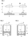
- the figures 1a and 1b show two configurations of a device known from the prior art.
- the device of the picture 1a comprises an optical lens 20 and a support, not shown, intended to receive a printed circuit 10 supporting a light source 12.
- the light source is for example a light-emitting diode, LED, in the form of an electronic chip, and having an emitting face of light 13.
- the support serves to hold the printed circuit at a predetermined distance which is such that the emitting face 13 of the source 12 is located at a distance F from the lens 20, corresponding to the focal length thereof.
- the support maintains the circuit 10 and the source 12 in a plane generally perpendicular to the optical axis of the lens.
- the same device is used by mounting a different type LED 14 on the printed circuit 10.
- the LED 14 is characterized by a greater height with respect to the plane of the printed circuit 10, compared to the LED 12. Consequently, the face emitter 15 is found closer to the lens 20 is not located at the focal distance F of the latter.
- Such devices are commonly used in the prior art, although they necessarily generate deteriorated light performance in the case of Figure 1b .
- the device comprises a printed circuit 110 which is received by a support 100.
- the support is arranged so as to receive the printed circuit in a manner generally perpendicular to the optical axis of an optical lens 120, and this at at least two distinct distances relative to the position of the lens.
- the printed circuit comprises, on the face which is oriented towards the lens 120, a light source 112 which is for example a light-emitting diode, LED, having an emitting surface 113.
- the arrangement is such that the emitting surface is generally perpendicular to the optical axis and that the LED 112 emits light rays in the direction of the lens 120 when powered.
- the printed circuit may in particular comprise other electronic components, implementing for example means for controlling the power supply of the light source shown.
- such means can be offset with respect to the printed circuit and connected to the latter by an electrical connection.
- means for controlling the power supply of the light source make it possible to convert a current of a given intensity, supplied for example by a battery of the motor vehicle equipped by the device, into a charging current of a different intensity. and capable of powering the light source.
- Such means are well known in the art and their operation will not be described in more detail in the context of the present invention.
- the printed circuit 110 only comprises a single light source associated with an optical lens 120, it is obvious that the printed circuit can comprise a plurality of such sources each associated with an optical lens 120.
- the lens 120 defines a focal distance F.
- the distances predetermined by the support 100 are such that at least one mounting distance is provided to receive therein the printed circuit carrying the source 112, so that the emitting face 113 of the source is located at distance F from the optical lens 120.
- the support includes arms which extend generally parallel to the optical axis of the lens 120 from two opposite sides thereof . Both arms include symmetrically arranged notches. A notch of one arm is located in the same plane perpendicular to the optical axis of the lens 120 as the corresponding notch of the other arm. The notches of one arm are oriented towards those of the other. These notches make it possible to support the edges of the printed circuit 110 as illustrated.
- the choice of the location of the notches is made according to the type of LED 112 to be used in the device, each type of LED potentially having a different height on the printed circuit. LEDs known in the art have for example heights on circuit ranging from 0.6 mm to 1.8 mm.
- the notches or support means 102, 104 define two mounting distances of the printed circuit 110 relative to the lens 120. The first distance is adapted to the use of an LED of a first type 112. As illustrated by the picture 3 , the second distance is adapted to the use of an LED of a second type 114 of greater height on the printed circuit 110.
- the support 100 allows the optimal mounting of the two types of LED 112, 114 which results in the placement respective emitting surfaces 113, 115 at the focal length of the lens 120, thereby optimizing the optical properties of the device. It is clear that the example shown can be scaled without departing from the scope of the invention, for example by providing three or more predetermined distances.
- THE Figure 4 And 5 show an embodiment of the device according to the invention.
- THE Figure 4a and 4b illustrate a first configuration of this device.
- a printed circuit 210 populated on its two faces with light-emitting diodes 212, 214 of two different types is illustrated. In general, it suffices for one or the other of the faces of the printed circuit 210 to be populated with light-emitting diodes of the type 212 or 214 respectively.
- the printed circuit 210 has the particularity that it is capable of cooperating with the first support means 202 of the support 200 when the face carrying the diode 212 is oriented towards the lens 220, and when the opposite face carrying the diode 214 is oriented towards the lens 220, it is able to cooperate with the second support means 204.
- the distance predetermined by the first support means 202 is such that, when the printed circuit is received by these means, the emitting surface 213 of the diode 212 is located at the focal distance F with respect to the lens 220. This is illustrated by there figure 4a .
- the distance predetermined by the second support means 204 is such that, when the printed circuit is received by these means, the emitting surface 215 of the diode 213 is located at the focal distance F with respect to the lens 220. This is shown by there figure 5a .
- the support means 202, 204 extend in pairs in the form of arms or ribs on either side of the lens 220, generally parallel to the optical axis thereof.
- the first support means 202 extend over a lesser distance than the second support means 204, thus defining a first distance less than a second distance.
- the printed circuit 210 comprises, on its first face carrying the first type of source 212, notches 217 placed so as to cooperate with the end pieces of the first support means 202.
- the printed circuit 210 further comprises through holes, notches or vias 216, allowing the second support means 204 to pass through the printed circuit when the circuit is received at the first distance. This is illustrated by the figures 4a and 4b .
- notches or holes 216 are such that, when the printed circuit is turned over on itself so as to orient the light source 214 towards the lens 220, the second means 204 cannot pass through the printed circuit 210. Indeed, notches 218 intended to cooperate with the end pieces of the second support means 204 are provided on the second face of the printed circuit. This is illustrated by the figures 5a and 5b . A possible implementation is given by the figure 4 And 5 . It goes without saying that, depending on the geometry of the support means 202, 204, notches or holes are to be provided at places different from those which are illustrated, in order to guarantee the operation described. Such modifications will nevertheless be within the reach of those skilled in the art and remain within the scope of the present invention.
- the support 200 comprising the support means 202, 204 is preferably integral with the optical lens 220.
- the lens can for example be made of glass, other suitable materials being known to those skilled in the art.
- FIG. 6 shows another embodiment of the device according to the invention in a first configuration.
- the principle is identical to that which has just been described for the figure 4 And 5 respectively.
- a printed circuit 310 is supported in a first orientation with respect to a lens 320. In this orientation, a first face of the circuit comprising a first type of LED 312 is oriented towards the lens 320. The distance between the emitting face 313 of the LED and the lens 320 is predetermined by first support means 302.
- the printed circuit further comprises holes arranged so as to allow the passage of second support means 304, when the first face of the printed circuit is oriented towards the lens 320.
- FIG. 7 takes over the device of the figure 6 in another configuration.
- the printed circuit 310 is turned over on itself with respect to the configuration of the figure 6 .
- the second face, opposite the first face is oriented towards the lens 320.
- the second support means 304 do not cross the printed circuit but define the distance between the emitting face 315 of the second type of diode 314 mounted on the second face of the printed circuit 310.
- the distances predetermined by the first and second support means are such that the emitting faces of the first and second types of LEDs can be located at the fixed focal length of the lens 320.
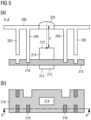
- FIG 8 shows another embodiment of the device according to the invention in a first configuration.
- a printed circuit 410 is supported in a first orientation with respect to a lens 420.
- a first face of the circuit comprising a first type of LED 412 is oriented towards the lens 420.
- the distance between the emitting face 413 of the LED and the lens 420 is predetermined by first support means 402.
- the first and second support means 402, 404 are made in one piece.
- the printed circuit comprises holes arranged so as to allow the passage of the second support means 404, when the first face of the printed circuit is oriented towards the lens 420.
- the first support means 402, wider than the second support means 404 rest on the outline of the holes.
- FIG. 9 takes over the device of the figure 8 in a second configuration.
- the printed circuit 410 is turned over on itself with respect to the configuration of the figure 8 .
- the second face, opposite the first face is oriented towards the lens 420.
- the second support means 404 do not cross the printed circuit but define the distance between the emitting face 415 of the second type of diode 414 mounted on the second face of the printed circuit 410.
- the distances predetermined by the first and second support means are such that the emitting faces of the first and second types of LEDs can be located at the fixed focal length of the lens 420.
- the device is preferably a stop light for the rear window of a motor vehicle.
Description
L'invention a trait au domaine des dispositifs lumineux de signalisation et/ou d'éclairage d'un véhicule automobile. Plus précisément, l'invention traite du domaine des feux arrière stop en position haute de lunette arrière de véhicule automobile.The invention relates to the field of luminous signaling and/or lighting devices for a motor vehicle. More specifically, the invention relates to the field of rear brake lights in the high position of the rear window of a motor vehicle.
Des dispositifs lumineux connus sont décrits dans les documents
Pour des raisons de sécurité, un véhicule automobile est généralement doté d'un feu stop additionnel en position centrale arrière. Ainsi, lorsque le conducteur du véhicule automobile freine, ce feu s'allume et éveille l'attention des usagers routiers qui le suivent. En étant disposé en position surélevée, par exemple en partie supérieure d'une lunette arrière, ce feu stop devient visible par une file d'usagers. De la sorte, davantage d'usagers successifs sont informés du changement de vitesse du conducteur qui freine en amont. Ils peuvent donc mieux anticiper les dangers, les conditions de circulation deviennent plus sûres.For safety reasons, a motor vehicle is generally equipped with an additional brake light in the rear central position. Thus, when the driver of the motor vehicle brakes, this light comes on and draws the attention of road users following him. By being arranged in a raised position, for example in the upper part of a rear window, this stop light becomes visible to a line of users. In this way, more successive users are informed of the change in speed of the driver who brakes upstream. They can therefore better anticipate dangers and traffic conditions become safer.
Pour améliorer sa visibilité tout en préservant le volume utile de l'habitacle du véhicule automobile, le feu stop peut être implanté de manière connue dans l'ouvrant du coffre arrière lorsque ce dernier rend la lunette arrière pivotante. Lorsque la lunette est fixe, le feu stop peut être rattaché au plafond de l'habitacle. Le feu stop s'étend verticalement depuis son support vers le bas. Il éclaire au travers de la lunette arrière du véhicule qui le reçoit, tout en restant discret dans l'habitacle.To improve its visibility while preserving the useful volume of the passenger compartment of the motor vehicle, the brake light can be installed in a known manner in the opening of the rear boot when the latter makes the rear window pivot. When the bezel is fixed, the brake light can be attached to the ceiling of the passenger compartment. The brake light extends vertically from its bracket downwards. It illuminates through the rear window of the vehicle receiving it, while remaining discreet in the passenger compartment.
Pour un type ou modèle de véhicule automobile donné, il est connu de développer un type de feu stop en position central arrière. Un tel dispositif comprend en général une ou plusieurs lentilles optiques associées à une ou plusieurs sources lumineuses, par exemple de type diode électroluminescente, LED. Le montage électronique comprenant les sources lumineuses est supporté en général par un circuit imprimé monté à un emplacement prédéterminé du dispositif. Il n'est en effet pas souhaitable de prévoir une pluralité de dispositifs pour différentes déclinaisons de configurations d'un même modèle de véhicule, notamment pour des raisons d'efficacité de production et de coûts de développement y associés.For a given type or model of motor vehicle, it is known to develop a type of brake light in the central rear position. Such a device generally comprises one or more optical lenses associated with one or more light sources, for example of the light-emitting diode, LED type. The electronic assembly comprising the light sources is generally supported by a printed circuit mounted at a predetermined location of the device. It is in fact not desirable to provide a plurality of devices for different variations of configurations of the same model of vehicle, in particular for reasons of production efficiency and associated development costs.
Pour des raisons de réglementation notamment au niveau de l'intensité du flux perçu du feu stop, il est souvent nécessaire d'utiliser des LEDs de différents types et de puissance différente sur un même modèle de véhicule, en fonction de la configuration du véhicule. En effet, si l'opacité de la glace de la lunette arrière à une influence sur la transmission de la lumière du feu stop, il en est de même pour le rayon de courbure et l'inclinaison de la glace.For regulatory reasons, in particular at the level of the intensity of the perceived flux of the brake light, it is often necessary to use LEDs of different types and of different power on the same model of vehicle, depending on the configuration of the vehicle. Indeed, if the opacity of the glass in the rear screen has an influence on the transmission of the light of the brake light, the same is true for the radius of curvature and the inclination of the glass.
Pourtant, si différents types de LEDs sont utilisés dans une même réalisation du feu stop, il en résulte des pertes d'efficacité. Le dispositif, et notamment la lentille optique, est en général adapté à un type de LED ou de source lumineuse donné. L'utilisation d'un type de source différent, pour lequel la position de la lentille optique n'a pas été optimisée au préalable, engendre en général un comportement non optimal du dispositif.However, if different types of LEDs are used in the same embodiment of the brake light, there is a loss of efficiency. The device, and in particular the optical lens, is generally adapted to a given type of LED or light source. The use of a different type of source, for which the position of the optical lens has not been optimized beforehand, generally generates non-optimal behavior of the device.
L'invention a pour objectif de pallier à au moins un des problèmes posés par l'art antérieur.The object of the invention is to overcome at least one of the problems posed by the prior art.
L'invention a pour objet un dispositif de signalisation et/ou d'éclairage d'un véhicule automobile tel que défini dans la revendication 1.The subject of the invention is a signaling and/or lighting device for a motor vehicle as defined in claim 1.
Des modes de réalisation préférentiels sont définis dans les revendications dépendantes.Preferred embodiments are defined in the dependent claims.
En utilisant les mesures selon l'invention, il devient possible de construire un type de feu stop en position centrale arrière ayant des propriétés optiques optimales pour une pluralité de types de sources de lumière, tout en utilisant la même lentille optique. La ou les lentilles optiques du dispositif définissent une distance focale fixe du dispositif. Lorsqu'une source lumineuse se situe à la distance focale par rapport à la lentille, les propriétés optiques du dispositif sont optimales. Comme des types de sources, notamment des types de LEDs différents sont des composants électroniques ayant des hauteurs différentes, l'invention prévoit un support permettant de monter différents types de LEDs par le biais de leur circuit imprimé à différentes distances prédéterminées par rapport à la lentille optique. Les distances sont avantageusement choisies de façon à ce que chaque distance correspond à un type de LED destiné à être utilisé dans le feu. Ceci veut dire que le montage d'un type de LED donné à la distance prédéterminée y associée a pour conséquence directe que la face émettrice de la LED se trouve à la distance focale de la lentille optique. Avantageusement, le support définissant les distances prédéterminées est venu de matière avec la lentille optique, ce qui assure que les distances sont invariables lors du montage du dispositif, puisqu'aucun alignement d'autres composants par rapport à la lentille n'est nécessaire.By using the measures according to the invention, it becomes possible to construct a type of rear center brake lamp having optimum optical properties for a plurality of types of light sources, while using the same optical lens. The at least one optical lens of the device defines a fixed focal length of the device. When a light source is located at the focal distance relative to the lens, the optical properties of the device are optimal. As different types of sources, in particular types of LEDs, are electronic components having different heights, the invention provides a support making it possible to mount different types of LEDs through their printed circuit at different predetermined distances with respect to the lens. optical. The distances are advantageously chosen so that each distance corresponds to a type of LED intended to be used in the light. This means that the mounting of a given type of LED at the predetermined distance associated with it has the direct consequence that the emitting face of the LED is located at the focal distance of the optical lens. Advantageously, the support defining the predetermined distances is integral with the optical lens, which ensures that the distances are invariable when mounting the device, since no alignment of other components with respect to the lens is necessary.
Des premiers moyens de support du dispositif sont aptes à maintenir un circuit imprimé à une première distance, tandis que des deuxièmes moyens de support sont aptes à maintenir un circuit imprimé à une deuxième distance. Un même circuit imprimé peut présenter sur chacune de ses deux faces des moyens pour coopérer respectivement avec les premiers et les deuxièmes moyens de support du dispositif. Le même circuit imprimé peut donc être monté à deux des distances prédéterminées par le dispositif. L'une et/ou l'autre des faces du circuit imprimé peut alors être peuplée de LEDs dont la hauteur est telle que leur face émettrice se trouve à la distance focale par rapport à la lentille optique. De cette façon, le même circuit imprimé peut être utilisé pour placer deux types de LEDs différents à des positions respectivement optimales et prédéterminées par rapport à la lentille optique. Ceci est réalisé sans engendrer des frais de développement supplémentaires et notamment sans nécessiter le changement d'autres composants du feu stop, comme par exemple la lentille optique.First support means of the device are able to hold a printed circuit at a first distance, while second support means are able to hold a printed circuit at a second distance. The same printed circuit can have on each of its two faces means for cooperating respectively with the first and second support means of the device. The same printed circuit can therefore be mounted at two of the distances predetermined by the device. One and/or the other of the faces of the printed circuit can then be populated with LEDs whose height is such that their emitting face is at the focal distance with respect to the optical lens. In this way, the same printed circuit can be used to place two different types of LEDs at respectively optimal and predetermined positions with respect to the optical lens. This is achieved without incurring additional development costs and in particular without requiring the change of other components of the brake light, such as for example the optical lens.
D'autres caractéristiques et avantages de la présente invention seront mieux compris à l'aide de la description exemplaire et des dessins parmi lesquels:
- les
figures 1a et 1b représentent une vue schématique d'une coupe latérale d'un dispositif connu de l'art antérieur dans deux configurations ; - la
figure 2 représente une vue schématique d'une coupe latérale d'un dispositif, qui n'est pas selon l'invention, dans une première configuration ; - la
figure 3 représente une vue schématique d'une coupe latérale du dispositif illustré par lafigure 2 dans une deuxième configuration ; - la
figure 4a représente une vue schématique d'une coupe latérale d'un dispositif selon un mode de réalisation de l'invention dans une première configuration ; - la
figure 4b représente un détail de la configuration illustrée par lafigure 4a dans une vue d'en haut ; - la
figure 5a représente une vue schématique d'une coupe latérale du dispositif illustré par lafigure 4a dans une deuxième configuration ; - la
figure 5b représente un détail de la configuration illustrée par lafigure 5a dans une vue d'en haut ; - la
figure 6 représente une vue schématique en perspective d'un dispositif selon un mode de réalisation de l'invention dans une première configuration ; - la
figure 7 représente une vue schématique en perspective du dispositif illustré par lafigure 6 dans une deuxième configuration. - la
figure 8 représente une vue schématique en perspective d'un dispositif selon un mode de réalisation de l'invention dans une première configuration ; - la
figure 9 représente une vue schématique en perspective du dispositif illustré par lafigure 8 dans une deuxième configuration.
- THE
figures 1a and 1b represent a schematic view of a side section of a device known from the prior art in two configurations; - there
figure 2 shows a schematic view of a side section of a device, which is not according to the invention, in a first configuration; - there
picture 3 shows a schematic view of a side section of the device illustrated by thepicture 2 in a second configuration; - there
figure 4a shows a schematic view of a side section of a device according to an embodiment of the invention in a first configuration; - there
figure 4b represents a detail of the configuration illustrated by thefigure 4a in a top view; - there
figure 5a shows a schematic view of a side section of the device illustrated by thefigure 4a in a second configuration; - there
figure 5b represents a detail of the configuration illustrated by thefigure 5a in a top view; - there
figure 6 shows a schematic perspective view of a device according to an embodiment of the invention in a first configuration; - there
figure 7 represents a schematic perspective view of the device illustrated by thefigure 6 in a second configuration. - there
figure 8 shows a schematic perspective view of a device according to an embodiment of the invention in a first configuration; - there
figure 9 represents a schematic perspective view of the device illustrated by thefigure 8 in a second configuration.
Dans la description qui suit, des numéros de référence similaires seront utilisés pour décrire des concepts similaires à travers des modes de réalisation différents de l'invention. Ainsi, les numéros 100, 200, 300, 400 décrivent un support dans trois modes de réalisation différents.In the following description, like reference numerals will be used to describe like concepts across different embodiments of the invention. Thus, the
Sauf indication spécifique du contraire, des caractéristiques techniques décrites en détail pour un mode de réalisation donné peuvent être combinées aux caractéristiques techniques décrites dans le contexte d'autres modes de réalisation décrits à titre exemplaire et non limitatif.Unless specifically indicated to the contrary, technical characteristics described in detail for a given embodiment can be combined with the technical characteristics described in the context of other embodiments described by way of example and not limitation.
Les
La
Bien que dans l'exemple montré le circuit imprimé 110 ne comprend qu'une seule source lumineuse associée à une lentille optique 120, il est évident que le circuit imprimé peut comprendre une pluralité de telles sources associées chacune à une lentille optique 120.Although in the example shown the printed
La lentille 120 définit une distance focale F. Les distances prédéterminées par le support 100 sont telles qu'au moins une distance de montage est prévue pour y recevoir le circuit imprimé portant la source 112, de façon à ce que la face émettrice 113 de la source se situe à la distance F par rapport à la lentille optique 120. Dans le mode de réalisation montré, le support comprend des bras qui s'étendent de manière généralement parallèle à l'axe optique de la lentille 120 de deux côtés opposés de celle-ci. Les deux bras comprennent des encoches arrangées symétriquement. Une encoche d'un bras se situe dans le même plan perpendiculaire à l'axe optique de la lentille 120 que l'encoche correspondante de l'autre bras. Les encoches d'un bras sont orientées vers celles de l'autre. Ces encoches permettent de supporter les bords du circuit imprimé 110 tel qu'illustré. Le choix de l'emplacement des encoches est fait en fonction du type de LED 112 à utiliser dans le dispositif, chaque type de LED ayant potentiellement une hauteur différente sur le circuit imprimé. Des LEDs connues dans l'art présentent par exemple des hauteurs sur circuit allant de 0.6 mm à 1.8 mm. Dans l'exemple de la
Les
La distance prédéterminée par les premiers moyens de support 202 est telle que, lorsque le circuit imprimé est reçu par ces moyens, la surface émettrice 213 de la diode 212 se situe à la distance focale F par rapport à la lentille 220. Ceci est illustré par la
Evidemment l'orientation du circuit imprimé est différente dans les deux cas, orientant soit l'une ou l'autre de ses deux faces vers la lentille.Obviously the orientation of the printed circuit is different in the two cases, directing either one or the other of its two faces towards the lens.
Les moyens de support 202, 204 s'étendent en paires sous forme de bras ou de nervures de part et d'autre de la lentille 220, de manière généralement parallèle à l'axe optique de celle-ci. Les premiers moyens de support 202 s'étendent sur une distance moins importante que les deuxièmes moyens de support 204, définissant ainsi une première distance inférieure à une deuxième distance. Le circuit imprimé 210 comprend, sur sa première face portant le premier type de source 212, des encoches 217 placées de façon à coopérer avec les embouts des premiers moyens de support 202. Le circuit imprimé 210 comprend en outre des trous, encoches ou vias traversants 216, permettant aux deuxièmes moyens de support 204 de passer à travers le circuit imprimé lorsque le circuit est reçu à la première distance. Ceci est illustré par les
La disposition des encoches ou trous 216 est telle que, lorsque le circuit imprimé est retourné sur lui-même de façon à orienter la source lumineuse 214 vers la lentille 220, les deuxièmes moyens 204 ne peuvent pas traverser le circuit imprimé 210. En effet, des encoches 218 destinées à coopérer avec les embouts des deuxièmes moyens de support 204 sont prévus sur la deuxième face du circuit imprimé. Ceci est illustré par les
Comme illustré, le support 200 comprenant les moyens de support 202, 204 est de préférence venu de matière avec la lentille optique 220. La lentille peut par exemple être en verre, d'autres matières convenables étant connues de l'homme du métier. En intégrant le support directement à la lentille, les distances prédéterminées par rapport à la lentille ne peuvent plus être altérées par erreur, même lors de l'assemblage du dispositif.As illustrated, the
La
La
La
La
Tandis que d'autres usages du dispositif sont envisageables, le dispositif est de préférence un feu de signalisation stop pour lunette arrière d'un véhicule automobile.While other uses of the device are possible, the device is preferably a stop light for the rear window of a motor vehicle.
Claims (6)
- Signalling and/or lighting device of a motor vehicle, comprising a printed circuit (210, 310, 410) received by a support (200, 300, 400), the printed circuit comprising at least one light source (212, 312, 412), an emitting side (213, 313, 413) of which is oriented towards an optical lens (220, 320, 420) of the device, the emitting side generally being perpendicular to the optical axis of the lens, the support (200, 300, 400) making it possible to receive the printed circuit (210, 310, 410) at at least two predetermined distinct distances with respect to the optical lens (220, 320, 420),- the support (200, 300, 400) comprising first support means (202, 302, 402) and second support means (204, 304, 404), respectively intended to receive the printed circuit (210, 310, 410) at a first distance and at a second distance, which is greater than the first distance, with respect to the optical lens (220, 320, 420), characterized in that:- the printed circuit comprises at least one light source of a first type (212) on a first side, and/or at least one light source of a second type (214) on an opposite second side, the height of the emitting side (215) of a light source of the second type (214) with respect to the plane defined by the printed circuit (210) being greater than the corresponding height of the emitting side (213) of a light source of the first type (212),- a first distance predetermined by the support (200) is such that the emitting side (213) of the light source of the first type (212) is located at the focal distance of the optical lens (220) when the printed circuit (210) is received at the first distance, the first side being oriented towards the lens (220), and in that a second distance predetermined by the support (200), which is greater than the first distance, is such that the emitting side (215) of the light source of the second type (214) is located at the focal distance of the optical lens (220) when the printed circuit (210) is received at the second distance, the second side being oriented towards the lens (220),- the first side of the printed circuit (210) comprises notches or recesses (217) intended to cooperate with the first support means (202), and in that the second side of the printed circuit comprises notches or recesses (216) intended to cooperate with the second support means (204), the arrangement of the support means (202, 204) and of the notches or recesses (216, 217, 218) of the printed circuit is such that, when the printed circuit (210) is received at the first distance, the first side being oriented towards the lens (220), the second support means (204) pass through the printed circuit.
- Device according to Claim 1, characterized in that the support means (202, 204; 302, 304; 402, 404) extend generally parallel to the optical axis of the lens (220, 320, 420) and are configured so as to cooperate with corresponding notches (217, 218) provided on the printed circuit (210, 310, 410).
- Device according to one of the preceding claims, characterized in that the light sources of the first type (212) are intended to emit a different luminous flux from the light sources of the second type (214).
- Device according to one of the preceding claims, characterized in that the optical lens (220, 320, 420) and the support (200, 300, 400) are formed as one piece.
- Device according to one of the preceding claims, characterized in that the light sources comprise a semiconductor element, notably a light-emitting diode, LED.
- Device according to one of the preceding claims, characterized in that the device is a stop light for a rear window of a motor vehicle.
Applications Claiming Priority (1)
| Application Number | Priority Date | Filing Date | Title |
|---|---|---|---|
| FR1555393A FR3037295B1 (en) | 2015-06-12 | 2015-06-12 | MOTOR VEHICLE REAR WINDOW REAR LIGHT ADAPTABLE TO MULTIPLE TYPES OF LIGHT SOURCES |
Publications (2)
| Publication Number | Publication Date |
|---|---|
| EP3104065A1 EP3104065A1 (en) | 2016-12-14 |
| EP3104065B1 true EP3104065B1 (en) | 2023-03-15 |
Family
ID=54066041
Family Applications (1)
| Application Number | Title | Priority Date | Filing Date |
|---|---|---|---|
| EP16173383.7A Active EP3104065B1 (en) | 2015-06-12 | 2016-06-07 | Signaling and/or lighting device of a motor vehicle |
Country Status (3)
| Country | Link |
|---|---|
| US (1) | US10118540B2 (en) |
| EP (1) | EP3104065B1 (en) |
| FR (1) | FR3037295B1 (en) |
Family Cites Families (7)
| Publication number | Priority date | Publication date | Assignee | Title |
|---|---|---|---|---|
| JP3839235B2 (en) * | 2000-09-18 | 2006-11-01 | 株式会社小糸製作所 | Vehicle lighting |
| JP4275363B2 (en) * | 2002-07-11 | 2009-06-10 | 京都電機器株式会社 | Lighting equipment for inspection |
| JP4094366B2 (en) | 2002-07-24 | 2008-06-04 | 株式会社小糸製作所 | Vehicle lighting |
| WO2005028250A1 (en) * | 2003-09-22 | 2005-03-31 | Decoma International Inc. | Vehicular light assembly |
| US20110273892A1 (en) * | 2010-05-07 | 2011-11-10 | Tyco Electronics Corporation | Solid state lighting assembly |
| KR20130032686A (en) * | 2011-09-23 | 2013-04-02 | 현대모비스 주식회사 | A lamp apparatus for vehicles |
| DE102012107834B4 (en) * | 2012-08-24 | 2021-02-04 | SMR Patents S.à.r.l. | Lighting device for inside or outside mirrors of a motor vehicle with a light guide unit which has groove-like recesses for fixing a light unit |
-
2015
- 2015-06-12 FR FR1555393A patent/FR3037295B1/en active Active
-
2016
- 2016-06-07 US US15/175,277 patent/US10118540B2/en active Active
- 2016-06-07 EP EP16173383.7A patent/EP3104065B1/en active Active
Also Published As
| Publication number | Publication date |
|---|---|
| US10118540B2 (en) | 2018-11-06 |
| EP3104065A1 (en) | 2016-12-14 |
| FR3037295B1 (en) | 2018-10-12 |
| FR3037295A1 (en) | 2016-12-16 |
| US20160362043A1 (en) | 2016-12-15 |
Similar Documents
| Publication | Publication Date | Title |
|---|---|---|
| EP2598796B1 (en) | Optical module of an illuminating and/or signalling device of a motor vehicle | |
| EP2607165B1 (en) | Lighting modul comprising at least two light sources arranged substantially perpendicularly | |
| FR2928110A1 (en) | OPTICAL SYSTEM WITH MAIN FUNCTION FOR MOTOR VEHICLE | |
| EP3455549B1 (en) | Rear vehicle signal light comprising several light functions | |
| EP2846081B1 (en) | Lighting and signalling device of a vehicle | |
| EP2888130A1 (en) | Lighting module comprising a control device detachably held on a support | |
| EP2926049B1 (en) | Vehicle signalling device with three-dimensional effect | |
| EP3104065B1 (en) | Signaling and/or lighting device of a motor vehicle | |
| FR3055691B1 (en) | DIFFRACTIVE SCREEN LIGHTING MODULE FOR MOTOR VEHICLE | |
| EP3024697A1 (en) | Lighting system, in particular for a motor vehicle lighting member, comprising a printed circuit board inclined in relation to the lighting direction | |
| FR3025289B1 (en) | LIGHTING AND / OR EXTERNAL SIGNALING PROJECTOR AND CORRESPONDING LIGHTING AND / OR SIGNALING SYSTEM | |
| FR3071036B1 (en) | OPTICAL MODULE FOR LIGHTING DEVICE AND / OR LIGHT SIGNALING DEVICE | |
| EP3508378A1 (en) | Lighting and/or signalling device for a motor vehicle | |
| FR3079597A1 (en) | OPTICAL MODULE FOR MOTOR VEHICLE | |
| EP3867565B1 (en) | Dual-function luminous module for an optical vehicle lighting and/or signalling unit | |
| EP2463155A2 (en) | Improved backlight device | |
| EP3867563B1 (en) | Light module providing two photometric functions having distinct light signatures | |
| EP3221185B1 (en) | Lighting unit for a vehicle and corresponding vehicle | |
| FR3052535A1 (en) | OPTICAL MODULE FOR A LIGHTING DEVICE FOR A MOTOR VEHICLE | |
| EP3054209B1 (en) | Lighting device for a motor vehicle | |
| FR3137435A1 (en) | Light module comprising at least two light sources whose respective optical axes intersect. | |
| JP6475953B2 (en) | Lighting device | |
| FR3062744A1 (en) | ALERT DEVICE AND METHOD FOR ADVISING USERS OF THE ROAD OF AN INCIDENT | |
| WO2017017161A1 (en) | Projection system for a display and head-up display | |
| FR3020120A1 (en) | LIGHT DIFFUSER SCREEN DEVICE FOR DIRECTION CHANGE INDICATOR |
Legal Events
| Date | Code | Title | Description |
|---|---|---|---|
| PUAI | Public reference made under article 153(3) epc to a published international application that has entered the european phase |
Free format text: ORIGINAL CODE: 0009012 |
|
| STAA | Information on the status of an ep patent application or granted ep patent |
Free format text: STATUS: THE APPLICATION HAS BEEN PUBLISHED |
|
| AK | Designated contracting states |
Kind code of ref document: A1 Designated state(s): AL AT BE BG CH CY CZ DE DK EE ES FI FR GB GR HR HU IE IS IT LI LT LU LV MC MK MT NL NO PL PT RO RS SE SI SK SM TR |
|
| AX | Request for extension of the european patent |
Extension state: BA ME |
|
| STAA | Information on the status of an ep patent application or granted ep patent |
Free format text: STATUS: REQUEST FOR EXAMINATION WAS MADE |
|
| 17P | Request for examination filed |
Effective date: 20170609 |
|
| RBV | Designated contracting states (corrected) |
Designated state(s): AL AT BE BG CH CY CZ DE DK EE ES FI FR GB GR HR HU IE IS IT LI LT LU LV MC MK MT NL NO PL PT RO RS SE SI SK SM TR |
|
| STAA | Information on the status of an ep patent application or granted ep patent |
Free format text: STATUS: EXAMINATION IS IN PROGRESS |
|
| 17Q | First examination report despatched |
Effective date: 20210218 |
|
| STAA | Information on the status of an ep patent application or granted ep patent |
Free format text: STATUS: EXAMINATION IS IN PROGRESS |
|
| REG | Reference to a national code |
Ref country code: DE Ref legal event code: R079 Ref document number: 602016078281 Country of ref document: DE Free format text: PREVIOUS MAIN CLASS: F21S0008100000 Ipc: F21S0043140000 |
|
| RIC1 | Information provided on ipc code assigned before grant |
Ipc: F21S 43/27 20180101ALI20211221BHEP Ipc: F21S 43/19 20180101ALI20211221BHEP Ipc: F21S 43/14 20180101AFI20211221BHEP |
|
| GRAP | Despatch of communication of intention to grant a patent |
Free format text: ORIGINAL CODE: EPIDOSNIGR1 |
|
| STAA | Information on the status of an ep patent application or granted ep patent |
Free format text: STATUS: GRANT OF PATENT IS INTENDED |
|
| INTG | Intention to grant announced |
Effective date: 20220302 |
|
| GRAJ | Information related to disapproval of communication of intention to grant by the applicant or resumption of examination proceedings by the epo deleted |
Free format text: ORIGINAL CODE: EPIDOSDIGR1 |
|
| STAA | Information on the status of an ep patent application or granted ep patent |
Free format text: STATUS: EXAMINATION IS IN PROGRESS |
|
| INTC | Intention to grant announced (deleted) | ||
| GRAP | Despatch of communication of intention to grant a patent |
Free format text: ORIGINAL CODE: EPIDOSNIGR1 |
|
| STAA | Information on the status of an ep patent application or granted ep patent |
Free format text: STATUS: GRANT OF PATENT IS INTENDED |
|
| INTG | Intention to grant announced |
Effective date: 20220922 |
|
| GRAS | Grant fee paid |
Free format text: ORIGINAL CODE: EPIDOSNIGR3 |
|
| GRAA | (expected) grant |
Free format text: ORIGINAL CODE: 0009210 |
|
| STAA | Information on the status of an ep patent application or granted ep patent |
Free format text: STATUS: THE PATENT HAS BEEN GRANTED |
|
| AK | Designated contracting states |
Kind code of ref document: B1 Designated state(s): AL AT BE BG CH CY CZ DE DK EE ES FI FR GB GR HR HU IE IS IT LI LT LU LV MC MK MT NL NO PL PT RO RS SE SI SK SM TR |
|
| REG | Reference to a national code |
Ref country code: CH Ref legal event code: EP Ref country code: GB Ref legal event code: FG4D Free format text: NOT ENGLISH |
|
| REG | Reference to a national code |
Ref country code: DE Ref legal event code: R096 Ref document number: 602016078281 Country of ref document: DE |
|
| REG | Reference to a national code |
Ref country code: IE Ref legal event code: FG4D Free format text: LANGUAGE OF EP DOCUMENT: FRENCH |
|
| REG | Reference to a national code |
Ref country code: AT Ref legal event code: REF Ref document number: 1554204 Country of ref document: AT Kind code of ref document: T Effective date: 20230415 |
|
| REG | Reference to a national code |
Ref country code: LT Ref legal event code: MG9D |
|
| P01 | Opt-out of the competence of the unified patent court (upc) registered |
Effective date: 20230603 |
|
| REG | Reference to a national code |
Ref country code: NL Ref legal event code: MP Effective date: 20230315 |
|
| PG25 | Lapsed in a contracting state [announced via postgrant information from national office to epo] |
Ref country code: RS Free format text: LAPSE BECAUSE OF FAILURE TO SUBMIT A TRANSLATION OF THE DESCRIPTION OR TO PAY THE FEE WITHIN THE PRESCRIBED TIME-LIMIT Effective date: 20230315 Ref country code: NO Free format text: LAPSE BECAUSE OF FAILURE TO SUBMIT A TRANSLATION OF THE DESCRIPTION OR TO PAY THE FEE WITHIN THE PRESCRIBED TIME-LIMIT Effective date: 20230615 Ref country code: LV Free format text: LAPSE BECAUSE OF FAILURE TO SUBMIT A TRANSLATION OF THE DESCRIPTION OR TO PAY THE FEE WITHIN THE PRESCRIBED TIME-LIMIT Effective date: 20230315 Ref country code: LT Free format text: LAPSE BECAUSE OF FAILURE TO SUBMIT A TRANSLATION OF THE DESCRIPTION OR TO PAY THE FEE WITHIN THE PRESCRIBED TIME-LIMIT Effective date: 20230315 Ref country code: HR Free format text: LAPSE BECAUSE OF FAILURE TO SUBMIT A TRANSLATION OF THE DESCRIPTION OR TO PAY THE FEE WITHIN THE PRESCRIBED TIME-LIMIT Effective date: 20230315 |
|
| PGFP | Annual fee paid to national office [announced via postgrant information from national office to epo] |
Ref country code: FR Payment date: 20230622 Year of fee payment: 8 Ref country code: DE Payment date: 20230613 Year of fee payment: 8 |
|
| REG | Reference to a national code |
Ref country code: AT Ref legal event code: MK05 Ref document number: 1554204 Country of ref document: AT Kind code of ref document: T Effective date: 20230315 |
|
| PG25 | Lapsed in a contracting state [announced via postgrant information from national office to epo] |
Ref country code: SE Free format text: LAPSE BECAUSE OF FAILURE TO SUBMIT A TRANSLATION OF THE DESCRIPTION OR TO PAY THE FEE WITHIN THE PRESCRIBED TIME-LIMIT Effective date: 20230315 Ref country code: NL Free format text: LAPSE BECAUSE OF FAILURE TO SUBMIT A TRANSLATION OF THE DESCRIPTION OR TO PAY THE FEE WITHIN THE PRESCRIBED TIME-LIMIT Effective date: 20230315 Ref country code: FI Free format text: LAPSE BECAUSE OF FAILURE TO SUBMIT A TRANSLATION OF THE DESCRIPTION OR TO PAY THE FEE WITHIN THE PRESCRIBED TIME-LIMIT Effective date: 20230315 |
|
| PG25 | Lapsed in a contracting state [announced via postgrant information from national office to epo] |
Ref country code: SM Free format text: LAPSE BECAUSE OF FAILURE TO SUBMIT A TRANSLATION OF THE DESCRIPTION OR TO PAY THE FEE WITHIN THE PRESCRIBED TIME-LIMIT Effective date: 20230315 Ref country code: RO Free format text: LAPSE BECAUSE OF FAILURE TO SUBMIT A TRANSLATION OF THE DESCRIPTION OR TO PAY THE FEE WITHIN THE PRESCRIBED TIME-LIMIT Effective date: 20230315 Ref country code: PT Free format text: LAPSE BECAUSE OF FAILURE TO SUBMIT A TRANSLATION OF THE DESCRIPTION OR TO PAY THE FEE WITHIN THE PRESCRIBED TIME-LIMIT Effective date: 20230717 Ref country code: ES Free format text: LAPSE BECAUSE OF FAILURE TO SUBMIT A TRANSLATION OF THE DESCRIPTION OR TO PAY THE FEE WITHIN THE PRESCRIBED TIME-LIMIT Effective date: 20230315 Ref country code: EE Free format text: LAPSE BECAUSE OF FAILURE TO SUBMIT A TRANSLATION OF THE DESCRIPTION OR TO PAY THE FEE WITHIN THE PRESCRIBED TIME-LIMIT Effective date: 20230315 Ref country code: CZ Free format text: LAPSE BECAUSE OF FAILURE TO SUBMIT A TRANSLATION OF THE DESCRIPTION OR TO PAY THE FEE WITHIN THE PRESCRIBED TIME-LIMIT Effective date: 20230315 Ref country code: AT Free format text: LAPSE BECAUSE OF FAILURE TO SUBMIT A TRANSLATION OF THE DESCRIPTION OR TO PAY THE FEE WITHIN THE PRESCRIBED TIME-LIMIT Effective date: 20230315 |
|
| PG25 | Lapsed in a contracting state [announced via postgrant information from national office to epo] |
Ref country code: SK Free format text: LAPSE BECAUSE OF FAILURE TO SUBMIT A TRANSLATION OF THE DESCRIPTION OR TO PAY THE FEE WITHIN THE PRESCRIBED TIME-LIMIT Effective date: 20230315 Ref country code: PL Free format text: LAPSE BECAUSE OF FAILURE TO SUBMIT A TRANSLATION OF THE DESCRIPTION OR TO PAY THE FEE WITHIN THE PRESCRIBED TIME-LIMIT Effective date: 20230315 Ref country code: IS Free format text: LAPSE BECAUSE OF FAILURE TO SUBMIT A TRANSLATION OF THE DESCRIPTION OR TO PAY THE FEE WITHIN THE PRESCRIBED TIME-LIMIT Effective date: 20230715 |
|
| REG | Reference to a national code |
Ref country code: DE Ref legal event code: R097 Ref document number: 602016078281 Country of ref document: DE |
|
| PG25 | Lapsed in a contracting state [announced via postgrant information from national office to epo] |
Ref country code: MC Free format text: LAPSE BECAUSE OF FAILURE TO SUBMIT A TRANSLATION OF THE DESCRIPTION OR TO PAY THE FEE WITHIN THE PRESCRIBED TIME-LIMIT Effective date: 20230315 |
|
| PLBE | No opposition filed within time limit |
Free format text: ORIGINAL CODE: 0009261 |
|
| STAA | Information on the status of an ep patent application or granted ep patent |
Free format text: STATUS: NO OPPOSITION FILED WITHIN TIME LIMIT |
|
| PG25 | Lapsed in a contracting state [announced via postgrant information from national office to epo] |
Ref country code: SI Free format text: LAPSE BECAUSE OF FAILURE TO SUBMIT A TRANSLATION OF THE DESCRIPTION OR TO PAY THE FEE WITHIN THE PRESCRIBED TIME-LIMIT Effective date: 20230315 Ref country code: MC Free format text: LAPSE BECAUSE OF FAILURE TO SUBMIT A TRANSLATION OF THE DESCRIPTION OR TO PAY THE FEE WITHIN THE PRESCRIBED TIME-LIMIT Effective date: 20230315 Ref country code: DK Free format text: LAPSE BECAUSE OF FAILURE TO SUBMIT A TRANSLATION OF THE DESCRIPTION OR TO PAY THE FEE WITHIN THE PRESCRIBED TIME-LIMIT Effective date: 20230315 |
|
| REG | Reference to a national code |
Ref country code: CH Ref legal event code: PL |
|
| 26N | No opposition filed |
Effective date: 20231218 |
|
| REG | Reference to a national code |
Ref country code: BE Ref legal event code: MM Effective date: 20230630 |
|
| GBPC | Gb: european patent ceased through non-payment of renewal fee |
Effective date: 20230615 |
|
| PG25 | Lapsed in a contracting state [announced via postgrant information from national office to epo] |
Ref country code: LU Free format text: LAPSE BECAUSE OF NON-PAYMENT OF DUE FEES Effective date: 20230607 |
|
| REG | Reference to a national code |
Ref country code: IE Ref legal event code: MM4A |
|
| PG25 | Lapsed in a contracting state [announced via postgrant information from national office to epo] |
Ref country code: LU Free format text: LAPSE BECAUSE OF NON-PAYMENT OF DUE FEES Effective date: 20230607 |
|
| PG25 | Lapsed in a contracting state [announced via postgrant information from national office to epo] |
Ref country code: IE Free format text: LAPSE BECAUSE OF NON-PAYMENT OF DUE FEES Effective date: 20230607 |