EP3103750A1 - Yarn winding machine and spinning machine - Google Patents
Yarn winding machine and spinning machine Download PDFInfo
- Publication number
- EP3103750A1 EP3103750A1 EP16172616.1A EP16172616A EP3103750A1 EP 3103750 A1 EP3103750 A1 EP 3103750A1 EP 16172616 A EP16172616 A EP 16172616A EP 3103750 A1 EP3103750 A1 EP 3103750A1
- Authority
- EP
- European Patent Office
- Prior art keywords
- yarn
- winding
- section
- bobbin
- package
- Prior art date
- Legal status (The legal status is an assumption and is not a legal conclusion. Google has not performed a legal analysis and makes no representation as to the accuracy of the status listed.)
- Granted
Links
- 238000004804 winding Methods 0.000 title claims abstract description 183
- 238000009987 spinning Methods 0.000 title claims abstract description 109
- 239000000835 fiber Substances 0.000 claims description 16
- 239000002994 raw material Substances 0.000 claims description 3
- 230000001276 controlling effect Effects 0.000 description 10
- 238000012806 monitoring device Methods 0.000 description 7
- 238000011144 upstream manufacturing Methods 0.000 description 6
- 238000009434 installation Methods 0.000 description 4
- 230000002401 inhibitory effect Effects 0.000 description 3
- 230000005540 biological transmission Effects 0.000 description 2
- 230000007547 defect Effects 0.000 description 2
- 238000001514 detection method Methods 0.000 description 2
- 239000000463 material Substances 0.000 description 2
- 230000003287 optical effect Effects 0.000 description 2
- 230000002159 abnormal effect Effects 0.000 description 1
- 230000003247 decreasing effect Effects 0.000 description 1
- 238000007689 inspection Methods 0.000 description 1
- 238000012423 maintenance Methods 0.000 description 1
- 238000007383 open-end spinning Methods 0.000 description 1
- 230000036961 partial effect Effects 0.000 description 1
- 238000002360 preparation method Methods 0.000 description 1
- 230000001105 regulatory effect Effects 0.000 description 1
- 230000002441 reversible effect Effects 0.000 description 1
- 239000000126 substance Substances 0.000 description 1
Images




Classifications
-
- B—PERFORMING OPERATIONS; TRANSPORTING
- B65—CONVEYING; PACKING; STORING; HANDLING THIN OR FILAMENTARY MATERIAL
- B65H—HANDLING THIN OR FILAMENTARY MATERIAL, e.g. SHEETS, WEBS, CABLES
- B65H54/00—Winding, coiling, or depositing filamentary material
- B65H54/70—Other constructional features of yarn-winding machines
- B65H54/74—Driving arrangements
-
- B—PERFORMING OPERATIONS; TRANSPORTING
- B65—CONVEYING; PACKING; STORING; HANDLING THIN OR FILAMENTARY MATERIAL
- B65H—HANDLING THIN OR FILAMENTARY MATERIAL, e.g. SHEETS, WEBS, CABLES
- B65H54/00—Winding, coiling, or depositing filamentary material
- B65H54/02—Winding and traversing material on to reels, bobbins, tubes, or like package cores or formers
- B65H54/22—Automatic winding machines, i.e. machines with servicing units for automatically performing end-finding, interconnecting of successive lengths of material, controlling and fault-detecting of the running material and replacing or removing of full or empty cores
-
- B—PERFORMING OPERATIONS; TRANSPORTING
- B65—CONVEYING; PACKING; STORING; HANDLING THIN OR FILAMENTARY MATERIAL
- B65H—HANDLING THIN OR FILAMENTARY MATERIAL, e.g. SHEETS, WEBS, CABLES
- B65H54/00—Winding, coiling, or depositing filamentary material
- B65H54/02—Winding and traversing material on to reels, bobbins, tubes, or like package cores or formers
- B65H54/40—Arrangements for rotating packages
- B65H54/52—Drive contact pressure control, e.g. pressing arrangements
-
- B—PERFORMING OPERATIONS; TRANSPORTING
- B65—CONVEYING; PACKING; STORING; HANDLING THIN OR FILAMENTARY MATERIAL
- B65H—HANDLING THIN OR FILAMENTARY MATERIAL, e.g. SHEETS, WEBS, CABLES
- B65H54/00—Winding, coiling, or depositing filamentary material
- B65H54/70—Other constructional features of yarn-winding machines
-
- B—PERFORMING OPERATIONS; TRANSPORTING
- B65—CONVEYING; PACKING; STORING; HANDLING THIN OR FILAMENTARY MATERIAL
- B65H—HANDLING THIN OR FILAMENTARY MATERIAL, e.g. SHEETS, WEBS, CABLES
- B65H63/00—Warning or safety devices, e.g. automatic fault detectors, stop-motions ; Quality control of the package
- B65H63/02—Warning or safety devices, e.g. automatic fault detectors, stop-motions ; Quality control of the package responsive to reduction in material tension, failure of supply, or breakage, of material
- B65H63/024—Warning or safety devices, e.g. automatic fault detectors, stop-motions ; Quality control of the package responsive to reduction in material tension, failure of supply, or breakage, of material responsive to breakage of materials
- B65H63/036—Warning or safety devices, e.g. automatic fault detectors, stop-motions ; Quality control of the package responsive to reduction in material tension, failure of supply, or breakage, of material responsive to breakage of materials characterised by the combination of the detecting or sensing elements with other devices, e.g. stopping devices for material advancing or winding mechanism
- B65H63/0364—Warning or safety devices, e.g. automatic fault detectors, stop-motions ; Quality control of the package responsive to reduction in material tension, failure of supply, or breakage, of material responsive to breakage of materials characterised by the combination of the detecting or sensing elements with other devices, e.g. stopping devices for material advancing or winding mechanism by lifting or raising the package away from the driving roller
-
- B—PERFORMING OPERATIONS; TRANSPORTING
- B65—CONVEYING; PACKING; STORING; HANDLING THIN OR FILAMENTARY MATERIAL
- B65H—HANDLING THIN OR FILAMENTARY MATERIAL, e.g. SHEETS, WEBS, CABLES
- B65H67/00—Replacing or removing cores, receptacles, or completed packages at paying-out, winding, or depositing stations
- B65H67/04—Arrangements for removing completed take-up packages and or replacing by cores, formers, or empty receptacles at winding or depositing stations; Transferring material between adjacent full and empty take-up elements
- B65H67/0405—Arrangements for removing completed take-up packages or for loading an empty core
- B65H67/0411—Arrangements for removing completed take-up packages or for loading an empty core for removing completed take-up packages
-
- B—PERFORMING OPERATIONS; TRANSPORTING
- B65—CONVEYING; PACKING; STORING; HANDLING THIN OR FILAMENTARY MATERIAL
- B65H—HANDLING THIN OR FILAMENTARY MATERIAL, e.g. SHEETS, WEBS, CABLES
- B65H75/00—Storing webs, tapes, or filamentary material, e.g. on reels
- B65H75/02—Cores, formers, supports, or holders for coiled, wound, or folded material, e.g. reels, spindles, bobbins, cop tubes, cans, mandrels or chucks
- B65H75/18—Constructional details
-
- D—TEXTILES; PAPER
- D01—NATURAL OR MAN-MADE THREADS OR FIBRES; SPINNING
- D01H—SPINNING OR TWISTING
- D01H9/00—Arrangements for replacing or removing bobbins, cores, receptacles, or completed packages at paying-out or take-up stations ; Combination of spinning-winding machine
- D01H9/02—Arrangements for replacing or removing bobbins, cores, receptacles, or completed packages at paying-out or take-up stations ; Combination of spinning-winding machine for removing completed take-up packages and replacing by bobbins, cores, or receptacles at take-up stations; Transferring material between adjacent full and empty take-up elements
- D01H9/04—Doffing arrangements integral with spinning or twisting machines
-
- B—PERFORMING OPERATIONS; TRANSPORTING
- B65—CONVEYING; PACKING; STORING; HANDLING THIN OR FILAMENTARY MATERIAL
- B65H—HANDLING THIN OR FILAMENTARY MATERIAL, e.g. SHEETS, WEBS, CABLES
- B65H2405/00—Parts for holding the handled material
- B65H2405/40—Holders, supports for rolls
-
- B—PERFORMING OPERATIONS; TRANSPORTING
- B65—CONVEYING; PACKING; STORING; HANDLING THIN OR FILAMENTARY MATERIAL
- B65H—HANDLING THIN OR FILAMENTARY MATERIAL, e.g. SHEETS, WEBS, CABLES
- B65H2701/00—Handled material; Storage means
- B65H2701/30—Handled filamentary material
- B65H2701/31—Textiles threads or artificial strands of filaments
Definitions
- the present invention relates to a yarn winding machine and a spinning machine.
- Yarn winding machines in which a package into which a yarn is wound by a winding section is supported at a higher level in a height direction compared to a yarn supplying section are known in the art.
- a yarn winding machine in operations requiring access to a package (for example, in yarn end preparation and the like), it may be difficult for an operator to reach the package with his hands, and / or hassles such as needing a step ladder may occur, potentially resulting in lowered workability.
- a yarn winding machine includes a yarn supplying section that supplies a yarn; a winding section that is arranged at a higher level than the yarn supplying section in a height direction and winds the yarn around a winding bobbin to form a package.
- the winding section includes a winding drum that rotates while being in contact with the winding bobbin or the package, and a bobbin supporting section that rotatably supports the winding bobbin.
- the yarn winding machine further includes a movement section that moves the bobbin supporting section from an upward position in the height direction with respect to the winding drum to a downward position on an operator's working passage side, and / or from an upward position toward the operator's working passage.
- the package when a package that is arranged at a higher level than the yarn supplying section in the height direction needs to be accessed, by moving the bobbin supporting section by the movement section, the package can be easily moved, for example, to be easily accessible to the operator. Consequently, it is possible to improve the workability during operations requiring access to the package.
- the movement section includes a pivoting mechanism that pivots the bobbin supporting section so that the bobbin supporting section moves to the downward position in the height direction. According to this configuration, it is possible to simplify the configuration of the movement section.
- the pivoting mechanism pivots the bobbin supporting section around a rotating shaft of the winding drum. According to this configuration, it is possible to achieve the rotation of the winding drum and the pivoting of the bobbin supporting section by using the same shaft.
- the movement section includes a sliding mechanism that slides the bobbin supporting section so that the bobbin supporting section moves to the downward position in the height direction. According to this configuration, labor can be saved by effectively using the weight of at least the package while moving the bobbin supporting section to the downward position in the height direction.
- the movement section includes a both-end supporting section that supports each of one side and other side of the bobbin supporting section in a shaft direction of the package. According to this configuration, the movement section can support the bobbin supporting section by having a high rigidity.
- the movement section includes a driving device that drives the bobbin supporting section so that the bobbin supporting section moves downward in the height direction with respect to the winding drum. According to this configuration, for example, even if the package is heavy, the bobbin supporting section can be operated easily and properly by the driving device.
- the above yarn winding machine can include a driving operating member that is operated by an operator and starts driving of the bobbin supporting section by the driving device; and a controlling section that inhibits, when the driving operating member is operated, a winding operation by the winding section.
- a driving operating member that is operated by an operator and starts driving of the bobbin supporting section by the driving device
- a controlling section that inhibits, when the driving operating member is operated, a winding operation by the winding section.
- the movement section includes a manually operating mechanism that moves the bobbin supporting section when operated by the operator. According to this configuration, the operator can manually move the bobbin supporting section.
- the above yarn winding machine further includes a case storing section that is arranged at a lower level than the yarn supplying section in the height direction, and can store a sliver case that accommodates a sliver, which is raw material of the yarn.
- a case storing section that is arranged at a lower level than the yarn supplying section in the height direction, and can store a sliver case that accommodates a sliver, which is raw material of the yarn.
- a spinning machine includes a drafting device that drafts a fiber bundle; an air spinning device that generates a yarn by applying twists to the fiber bundle drafted by the drafting device; a winding section that is arranged at a higher level than the air spinning device in a height direction, and winds the yarn around a winding bobbin to form a package.
- the winding section includes a bobbin supporting section that rotatably supports the winding bobbin.
- the spinning machine further includes a movement section that moves the bobbin supporting section downward in the height direction and / or toward an operator's working passage.
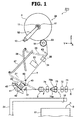
- a spinning machine (a yarn winding machine) 1 includes plural spinning units 2 arranged side-by-side, and a not-shown machine-frame controlling device that centrally controls the plural spinning units 2.
- Each of the spinning units 2 generates a yarn T by spinning a fiber bundle F, and winds the yarn T to form a package P.
- upstream and downstream refer to upstream and downstream in a traveling direction of the fiber bundle F and the yarn T during spinning.
- Each of the spinning units 2 includes a drafting device (a yarn supplying section) 7, an air spinning device (the yarn supplying section) 9, a yarn accumulating device 22, a yarn jointing device 23, a yarn monitoring device 25, and a winding device (a winding section) 26 in this order from upstream to downstream.
- Each device included in the spinning unit 2 is controlled by a not-shown unit controller arranged in the spinning unit 2.
- Each device included in the spinning unit 2 is mounted on a frame 31 (see FIG. 2 ). Alternatively, each device included in the spinning unit 2 can be controlled by the machine-frame controlling device.
- the spinning unit 2 includes a case storing section 18 that can store a sliver case 17 that contains a sliver S, which is raw material of the yarn T.
- the case storing section 18 is formed by a space secured in the frame 31.
- the sliver case 17 is arranged at a lower level than the drafting device 7 and the air spinning device 9 in a height direction.
- the sliver case 17 is accommodated inside the case storing section 18.
- the drafting device 7 stretches (drafts) the sliver S supplied from the sliver case 17 via a sliver guide until a predetermined fiber amount (or thickness) is obtained to form the fiber bundle F.
- the drafting device 7 includes a back roller pair 71, a third roller pair 72, a middle roller pair 73, and a front roller pair 74.
- An apron belt 75b and an apron belt 75a are stretched over a top roller and a bottom roller of the middle roller pair 73, respectively.
- the air spinning device 9 generates the yarn T by applying twists by using a swirling air current to the fiber bundle F drafted by the drafting device 7.
- the air spinning device 9 includes a spinning chamber, a fiber guiding section, a swirling air current generating nozzle, and a hollow guiding shaft.
- the fiber guiding section guides the fiber bundle F supplied from the drafting device 7 located upstream to the spinning chamber.
- the swirling air current generating nozzles are arranged surrounding a traveling path of the fiber bundle F.
- a swirling air current is generated in the spinning chamber by jetting air from the swirling air current generating nozzles.
- the fiber ends of the fibers constituting the fiber bundle F are reversed and whirled by this swirling air current.
- the hollow guiding shaft guides the yarn T from the inside of the spinning chamber to the outside of the air spinning device 9.
- a first guide 61 that guides the yarn T is arranged downstream of the air spinning device 9.
- the first guide 61 guides the yarn T to the yarn accumulating device 22.
- the first guide 61 is movable so that it can pull the yarn T to the yarn accumulating device 22 when performing yarn jointing and the like.
- the yarn accumulating device 22 is arranged downstream of the first guide 61.
- the yarn accumulating device 22 includes a yarn accumulating roller 41, an electric motor 42 that drives the yarn accumulating roller 41 to rotate, a yarn hooking member 43, and a residual yarn sucking device 45.
- the yarn T is temporarily accumulated by being wound around the outer circumferential surface of the yarn accumulating roller 41.
- the yarn hooking member 43 is mounted on a downstream end portion of the yarn accumulating roller 41.
- the yarn hooking member 43 is supported in a rotatable manner relatively to the yarn accumulating roller 41.
- a permanent magnet is attached to one of the yarn hooking member 43 and the yarn accumulating roller 41, and a magnetic hysteresis member is attached to the other one of the yarn hooking member 43 and the yarn accumulating roller 41.
- the yarn accumulating device 22 operates such that the yarn T is unwound when the yarn tension on the downstream is increased, and the yarn T is prevented from being unwound when the yarn tension is decreased (when the yarn T is about to have a slack). With this operation, the yarn accumulating device 22 can remove the slack of the yarn T and apply an appropriate tension on the yarn T. Furthermore, because the yarn hooking member 43 operates to absorb a variation of the tension applied on the yarn T between the yarn accumulating device 22 and the winding device 26, the variation of the tension is prevented from affecting the yarn T between the air spinning device 9 and the yarn accumulating device 22.
- the residual yarn sucking device 45 is arranged in an upstream end portion area of the yarn accumulating roller 41.
- the residual yarn sucking device 45 is connected to a not-shown blower, and can generate suction airflow.
- a second guide 62 that regulates the movement of the yarn T unwound from the yarn accumulating roller 41 is arranged downstream of the yarn accumulating roller 41.
- the yarn jointing device 23 is arranged downstream of the second guide 62.
- the yarn jointing device 23 joints a yarn T from the air spinning device 9 and a yarn T from the package P when the yarn T becomes discontinuous between the air spinning device 9 and the package P due to some reason.
- the yarn jointing device 23 is a splicer device that twists and joints the yarn ends by using the swirling air current generated by compressed air.
- the yarn jointing device 23, however, is not limited to the splicer device, and can be, for example, a mechanical knotter, and the like.
- the spinning unit 2 includes a first catching and guiding device 27 and a second catching and guiding device 28 that guide the yarn T to the yarn jointing device 23.
- the first catching and guiding device 27 is pivotable vertically around a base end portion thereof as a pivoting center.
- the first catching and guiding device 27 is hollow.
- the first catching and guiding device 27 is connected to the blower, and can generate the suction airflow.
- the first catching and guiding device 27 can catch an end of the yarn T from the air spinning device 9 by pivoting downward.
- the first catching and guiding device 27, after catching the yarn T from the air spinning device 9, guides the yarn T from the air spinning device 9 to the yarn jointing device 23 by pivoting upward.
- the second catching and guiding device 28 is pivotable vertically around a base end portion thereof as a pivoting center.
- the second catching and guiding device 28 also is hollow.
- the second catching and guiding device 28 is connected to the blower, and can generate the suction airflow.
- the second catching and guiding device 28 can catch an end of the yarn T from the package P by pivoting upward.
- the second catching and guiding device 28, after catching the yarn T from the package P, guides the yarn T from the package P to the yarn jointing device 23 by pivoting downward.
- the yarn jointing device 23 By driving the yarn jointing device 23 while being in a state in which the yarn T from the air spinning device 9 and the yarn T from the package P have been guided in the yarn jointing device 23, the yarn T from the air spinning device 9 and the yarn T from the package P are jointed, thereby causing the yarn T to be in a continuous state between the air spinning device 9 and the package P. With this action, the winding of the yarn T around the package P can be resumed.
- the yarn monitoring device 25 monitors a thickness of the traveling yarn T with a not-shown optical transmission type sensor.
- the yarn monitoring device 25 transmits, upon detecting a yarn defect (a part in which the thickness of the yarn T and the like is abnormal) in the yarn T, a yarn-defect detection signal to the unit controller.
- the unit controller drives a cutter 24 included in the yarn monitoring device 25, or stops the drafting device 7 to stop the supply of the sliver S, to cut the yarn T.
- the sensor with which the yarn monitoring device 25 monitors the thickness of the yarn T is not limited to the optical transmission type sensor, and can, for example, be a capacitance type sensor.
- the yarn monitoring device 25 can monitor a foreign substance contained in the yarn T as the yarn defect. As long as the cutter 24 is arranged between the yarn accumulating device 22 and the winding device 26, the cutter 24 can be arranged separately from the yarn monitoring device 25.
- the winding device 26 winds the yarn T generated by the air spinning device 9 around a winding bobbin 51 thereby forming the package P.
- the winding device 26 includes a cradle 52 and a winding drum 53. A yarn path from the yarn accumulating device 22 to the winding device 26 is guided by a downstream guide 63.
- the cradle 52 rotatably supports the winding bobbin 51 around which the yarn T is to be wound.
- a bobbin supporting section 11 that rotatably and removably supports each end portion of the winding bobbin 51 is arranged at each end portion of the cradle 52.
- the bobbin supporting section 11 is a bobbin holder that is rotatably supported via bearings at each end portion of the cradle 52.
- a pivoting shaft 12 is arranged at a base end portion of the cradle 52.
- the cradle 52 is pivotable around the pivoting shaft 12.
- the cradle 52 By pivoting around the pivoting shaft 12, the cradle 52 absorbs increase in a diameter of the package P due to the winding of the yarn T around the winding bobbin 51. With this configuration, even when a diameter of the package P increases with the winding of the yarn T around the winding bobbin 51, the winding of the yarn T can be continued properly.
- the winding drum 53 rotates while being in contact with an outer circumferential surface of the winding bobbin 51 or the package P because of a driving force transmitted from a winding-drum driving motor 54 (see FIG. 3 ).
- a not-shown traverse groove is formed on an outer circumferential surface of the winding drum 53, and the yarn T can be traversed to a predetermined width by using this traverse groove.
- the winding device 26 can form the package P by winding the yarn T around the winding bobbin 51 while traversing the yarn T. In this manner, because a separate winding-drum driving motor 54 is arranged for each spinning unit 2 in the spinning machine 1, the winding drum 53 of each spinning unit 2 can be rotated individually.
- the winding device 26 is arranged at a higher level than the drafting device 7 and the air spinning device 9 in the height direction (vertical direction with respect to an installation surface (floor) where the spinning machine 1 has been installed) during the operation of winding the yarn T (hereinafter, simply referred to as "during the winding operation").
- the package P, the cradle 52, and the bobbin supporting section 11 and the bearings thereof are arranged at a higher level than the drafting device 7 and the air spinning device 9 in the height direction (for example, above the operator's head).
- the yarn accumulating device 22 that is arranged between the air spinning device 9 and the winding device 26 changes the traveling direction of the yarn T.
- a surrounding configuration of the package P in the spinning unit 2 is explained below in detail with reference to FIGS. 2 and 3 .
- the height direction is explained as a Z direction
- the shaft direction of the package P (the winding bobbin 51) as an X direction
- the direction perpendicular to the X direction and Z direction as a Y direction.
- the winding drum 53 is rotatably supported by stays 32 that are arranged on an upper surface 31a of the frame 31 in the standing manner.
- the two stays 32 are arranged opposite to each other at both end portions in the X direction on the upper surface 31a.
- the winding drum 53 is arranged such that a rotating shaft 14 thereof is arranged along the X direction, and the rotating shaft 14 is inserted into the stays 32 via bearings 33.
- a winding drum pulley 34 is fixed to one end portion of the rotating shaft 14.
- the winding drum pulley 34 is linked via a belt 36 to a drum motor pulley 35 that is fixed to a rotating shaft 15 of the winding-drum driving motor 54.
- the winding drum pulley 34 and the drum motor pulley 35 are rotatable in synchronization with each other, and the driving force of the winding-drum driving motor 54 is transmittable to the winding drum 53.
- the spinning unit 2 includes a movement section 80, an operation button (a driving operating member) 95, and a winding controlling section (a controlling section) 97.
- the movement section 80 moves the bobbin supporting section 11 downward in the Z direction. Specifically, the movement section 80 moves the bobbin supporting section 11, with respect to the winding drum 53, from an upward position in the Z direction to a downward position on an operator's working passage side that is explained later.
- the movement section 80 can move the bobbin supporting section 11 between a higher position compared to the winding drum 53 and a lower position on the operator's working passage side compared to the winding drum 53.
- the movement section 80 can move (lower) at least the package P downward in the Z direction.
- the movement section 80 can move the cradle 52 so that the package P moves downward on the operator's working passage side in the Z direction, with respect to the winding drum 53.
- the movement section 80 includes a pivoting mechanism 81 that pivots the cradle 52 around the rotating shaft 14 of the winding drum 53, and a motor (a driving device) 82 that drives the pivoting mechanism 81.
- the pivoting mechanism 81 includes a pair of supporting plates 83.
- the X direction is a thickness direction
- each of the supporting plates 83 includes a main surface along the Z direction and the Y direction.
- the supporting plates 83 are arranged in a pair, opposite to each other at the both end portions in the X direction on the upper surface 31a of the frame 31.
- a through-hole 85 is formed on one side of each of the two supporting plates 83 in the Y direction.
- the rotating shaft 14 of the winding drum 53 is rotatably inserted into the through-holes 85 via bearings 84.
- the supporting plates 83 are pivotably supported around the rotating shaft 14.
- An edge among the edges of the supporting plate 83 that is positioned at a downward side during the winding operation has a shape that follows the upper surface 31a of the frame 31.
- the edges of the supporting plates 83 include flanges 83y that bent outside in the X direction. The flanges 83y come into contact with the upper surface 31a of the frame 31 during the winding operation.
- a through-hole 87 is formed at the center thereof in the Y direction.
- the rotating shaft 15 of the winding-drum driving motor 54 is rotatably inserted into the through-hole 87 via a bearing 86.
- a main body 54a of the winding-drum driving motor 54 is fixed to the supporting plate 83p. With this configuration, the supporting plate 83p supports the winding-drum driving motor 54 by making the rotating shaft 15 rotatable.
- a through-hole 89 is formed in the Y direction on other side of each of the two supporting plates 83.
- the pivoting shaft 12 of the cradle 52 is pivotably inserted into the through-holes 89 via bearings 88.
- the pair of the supporting plates 83 pivotably provides both-end support to the both end portions of the pivoting shaft 12.
- Each of the two supporting plates 83 supports one side and the other side of the bobbin supporting section 11 in the X direction, respectively.
- the pair of the supporting plates 83 forms a both-end supporting section.
- the supporting plate 83p includes a pulley member 90 that is arranged in the periphery of the through-hole 85.
- the pulley member 90 has a circular shape, and is linked via a belt 92 to a motor pulley 91 that is explained later. With this configuration, the motor pulley 91 and the pulley member 90 are rotatable in synchronization with each other, and the driving force of the motor 82 is transmittable to the supporting plate 83p.
- the pulley member 90 has a larger inner diameter than the outer diameter of the rotating shaft 14 so that the pulley member 90 does not come into contact with the rotating shaft 14 of the winding drum 53.
- the motor 82 is a driving device that drives the cradle 52 so that the bobbin supporting section 11 moves to the downward position in the Z direction with respect to the winding drum 53.
- the motor pulley 91 is fixed to a tip end part of a rotating shaft 16 of the motor 82.
- the motor pulley 91 is linked to the pulley member 90 of the supporting plate 83p via the belt 92.
- the driving force to rotate the pulley member 90 around the rotating shaft 14 is transmitted to the pulley member 90.
- the supporting plate 83p pivots around the rotating shaft 14. Consequently, the cradle 52 that is supported by the supporting plate 83p, the package P that is supported by the cradle 52, and the winding-drum driving motor 54 held by the supporting plate 83p pivot in an integrated manner around the rotating shaft 14.
- the operation button 95 By operating the operation button 95, the driving of the cradle 52 by the motor 82 is started.
- the operation button 95 is electrically connected to the motor 82.
- the operation button 95 outputs, when operated by the operator, a driving start signal to the motor 82 to rotate the rotating shaft 16 of the motor 82, and starts pivoting the supporting plate 83p and thereby the cradle 52.
- the operation button 95 is electrically connected to the winding controlling section 97.
- the operation button 95 outputs, when operated by the operator, a winding inhibiting signal to the winding controlling section 97.
- the winding controlling section 97 inhibits the winding operation by the winding device 26.
- the winding controlling section 97 controls the winding-drum driving motor 54, if the rotating shaft 15 of the winding-drum driving motor 54 is rotating, to stop the rotation of the rotating shaft 15, or if the rotating shaft 15 of the winding-drum driving motor 54 is not rotating, to maintain the stop state.
- the package P is supported by the cradle 52 and contacts the winding drum 53.
- the pair of the supporting plates 83 provides the both-end support to the both end portions of the pivoting shaft 12 of the cradle 52.
- Each of the two supporting plates 83 supports one side and the other side of the bobbin supporting section 11 in the X direction, respectively.
- the bobbin supporting section 11 is arranged at the upward position in the Z direction with respect to the winding drum 53.
- the supporting plates 83 while being in contact with the upper surface 31a of the frame 31, are pivotably supported by the rotating shaft 14 of the winding drum 53.
- the supporting plates 83 are pressed against the upper surface 31a of the frame 31 by the weight of the package P and the cradle 52, and are in a stable state (a non-pivoting state without being aware of the disturbance force).
- the operation button 95 is operated by the operator, and the rotating shaft 16 of the motor 82 starts rotating in one direction. Simultaneously, the rotation of the rotating shaft 15 of the winding-drum driving motor 54 is inhibited thereby inhibiting the winding operation.
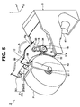
- the supporting plates 83 pivot the flanges 83y in a separating direction from the upper surface 31a in an A direction around the rotating shaft 14. Following the pivoting of the supporting plate 83, the cradle 52, the bobbin supporting section 11, and the package P pivot in the A direction.
- the "front side” explained in the present embodiment is a front side (the left side shown in FIGS. 4 to 6 ) of the spinning unit 2, and is the operator's working passage side where the operator walks.
- the operator's working passage side is a side where a large space is secured around the spinning unit 2 on one or the other side of the spinning unit 2 in the Y direction.
- an inlet (upstream) of the drafting device 7 is arranged on the operator's working passage side, resulting in easy access to the drafting device 7 for the operator.
- the first catching and guiding device 27 and the second catching and guiding device 28 are arranged on the opposite side of the operator's working passage.
- the pivoting shaft 12 of the cradle 52 is arranged on the opposite side of the operator's working passage with respect to the winding drum 53.
- the rotating shaft 16 of the motor 82 is continued to be rotated in the one direction.
- the supporting plates 83 pivot in an A direction
- the cradle 52, the bobbin supporting section 11, and the package P pivot in the A direction.
- the package P achieves the state of being suspended from the rotating shaft 14 via the cradle 52.
- the package P, the cradle 52, the bobbin supporting section 11 of the cradle 52 and the bearings thereof are positioned at a lower position in the Z direction compared to the winding drum 53, and at separate positions from the winding drum 53 toward the front side in the Y direction (nearer to the operator's working passage than the winding drum 53).
- the rotation of the rotating shaft 16 of the motor 82 is stopped. With the operation explained above, the package P moves downward in the Z direction with respect to the winding drum 53 (see FIGS. 4 and 6 ).
- the winding device 26 returns to the state during the winding operation shown in FIG. 4 after passing through the state shown in FIG. 5 from the state shown in FIG. 6 .
- the package P moves upward in the Z direction with respect to the winding drum 53 such that the package P returns to the position assumed during the winding operation.
- the package P that is positioned at a higher level than the drafting device 7 and the air spinning device 9 during the winding operation can be moved by the movement section 80 to the downward position in the Z direction and toward the operator's working passage. With this action, the package P can be easily lowered and can be drawn toward the operator's working passage to make the package P accessible to the operator.
- the movement section 80 includes the pivoting mechanism 81 that is provided with the supporting plates 83.
- the pivoting mechanism 81 pivots the cradle 52 along the A direction so that the package P is moved downward in the Z direction. According to this configuration, it is possible to simplify the configuration of the movement section 80.
- the supporting plates 83 of the pivoting mechanism 81 pivot the cradle 52 along the A direction around the rotating shaft 14 of the winding drum 53. According to this configuration, it is possible to achieve the rotation of the winding drum 53 and the pivoting of the cradle 52 in the A direction by using the same shaft.
- each of the two supporting plates 83 supports each end portion of the pivoting shaft 12 of the cradle 52.
- the movement section 80 can provide both-end support to the cradle 52, can support the cradle 52 by having high rigidity, and can prevent the damage of the winding device 26 due to lowering of the package P.
- the spinning machine 1 includes the motor 82.
- the cradle 52 is operated by the driving force of the motor 82, without requiring a human power, to lower the package P. According to this configuration, even if the package P and the cradle 52 are heavy, the cradle 52 can be operated easily and properly by the motor 82.
- the winding operation is not performed by only the winding device 26 in the spinning unit 2 for which the operation button 95 is operated so that the winding operation by the winding devices 26 in the other spinning units 2 can be continued.
- the spinning machine 1 further includes the case storing section 18 that can store the sliver case 17 that is arranged at a lower level than the drafting device 7 and the air spinning device 9 in the Z direction. According to this configuration, even if the height (distance between the installation surface of the spinning machine 1 and the upper side of the winding device 26) of the entire spinning machine 1 is higher for the operator due to the height of the sliver case 17, the operator can easily move the package P, for example, so that the package P is accessible to the operator by moving the bobbin supporting section 11 through the movement section 80.
- the cradle 52 and surrounding sections thereof can be collectively lowered by the action of the movement section 80.
- the spinning machine 1 can be configured so that the winding-drum driving motor 54 is not lowered.
- the spinning machine 1 can include a not-shown stopper) to regulate the operation of the movement section 80 during the winding operation, in other words, the pivoting of the supporting plates 83 around the rotating shaft 14.
- the spinning machine 1 can exert redundant force on the movement section 80 by applying a standby current to the motor 82 to regulate the operation of the movement section 80.
- a change in the state of the winding device 26 from the state shown in FIG. 4 as the movement section 80 is unintentionally operated by, for example, vibrations and the like, can be regulated.
- the stopper for example, a latching mechanism can be employed.
- the configuration of the spinning unit 2 is not limited to the configuration where it includes the pivoting mechanism 81 that pivots the package P, the bobbin supporting section 11, and the cradle 52.
- the spinning unit 2 can include a sliding mechanism 93 that slides the cradle 52 so that the bobbin supporting section 11 moves to a downward position in the Z direction, for example, as shown in FIGS. 7A and 7B .
- the spinning machine 1 can include a movement section that moves the bobbin supporting section 11 to the downward position in the Z direction and / or toward the operator's working passage.
- the upper surface 31a of the frame 31 has an inclined surface that is inclined with respect to a horizontal surface (the installation surface of the spinning machine 1).
- the sliding mechanism 93 supports the cradle 52, and is movable in a straight line along the upper surface 31a.
- An air cylinder 94 is arranged as a driving device that drives the sliding mechanism 93.
- the air cylinder 94 starts the driving of the sliding mechanism 93.
- the cradle 52 slides, by using the sliding mechanism 93, on the upper surface 31a so that the bobbin supporting section 11 moves downward in the Z direction on the operator's working passage side (see FIG. 7B ).
- the pivoting mechanism 81 (the supporting plates 83) pivots around the rotating shaft 14 of the winding drum 53
- the pivoting mechanism 81 can be caused to pivot around other shaft.
- a shaft, different from the rotating shaft 14, can be arranged, and the pivoting mechanism 81 can pivot around this shaft.
- the spinning unit 2 includes the motor 82 as a driving device, but the driving device is not limited to the motor 82.
- the spinning unit 2 can include any other actuator as a driving device. As long as the device can drive the cradle 52 so that the package P moves downward in the Z direction, other known driving means can be employed.
- the movement section 80 of the spinning unit 2 includes a driving device.
- the movement section 80 can include a manually operating mechanism with which the operator can manually operate the cradle 52.
- a manually operating mechanism a configuration including one or more gears and an operation lever can be used.
- the one or plural gears can be linked to the pulley member 90 of the supporting plate 83p, and the supporting plate 83p is pivoted by the operator by operating these gears through the operation lever.
- the manually operating mechanism the operator can manually move the cradle 52.
- the package P can be moved downward in the Z direction by rotating the cradle 52 toward the operator's working passage around of the pivoting shaft 12.
- the above embodiments need not include a two-stage pivoting mechanism, that is, a mechanism in which the supporting plates 83 pivotably support the cradle 52 with the pivoting shaft 12, and the rotating shaft 14 of the winding drum 53 pivotably supports the supporting plates 83.
- the pivoting shaft 12 constitutes the pivoting mechanism.
- the pair of the supporting plates 83 provides the both-end support to the pivoting shaft 12 of the cradle 52.
- the supporting plate 83p is sufficiently rigid, one end portion of the pivoting shaft 12 of the cradle 52 can be supported by the supporting plate 83p.
- the yarn winding machine (the spinning machine) of the present invention can include a both-end supporting section that supports both end portions of the cradle in the X direction in which the bobbin supporting section is arranged, or can include a one-end supporting section that supports one or the other end portion of the cradle in the X direction in which the bobbin supporting section is arranged.
- the yarn accumulating device 22 includes a function that pulls the yarn T from the air spinning device 9; however, a delivery roller and a nip roller can be used to pull the yarn T from the air spinning device 9.
- a slack tube that absorbs the slack of the yarn T by using the suction airflow, or a mechanical compensator, and the like can be provided.
- the bobbin supporting section 11 can move from the position during the winding operation to the opposite side of the operator's working passage side, and can guide the package P to a not-shown package loading section (such as conveyor) that is installed on the back side of the spinning unit 2 in the Y direction.
- a not-shown package loading section such as conveyor
- the uppermost end position of the winding drum 53 may be at a higher position than the uppermost end position of the package P.
- the yarn T can be wound into a cheese-shaped package P or a cone-shaped package P.
- the material and shape of various components explained above are not limited to those mentioned here, and it is possible to adopt various materials and shapes.
- the application of the yarn winding machine of the present invention is not limited to the spinning machine 1, and it can be applied to other yarn winding machines such as an automatic winder or an open-end spinning frame.
- the movement section 80 moves the bobbin supporting section 11 with respect to the winding drum 53 from the upward position toward the operator's working passage (front side) (see FIG. 5 ), and then moves the bobbin supporting section 11 to the downward position with respect to the winding drum 53 (see FIG. 6 ).
- the movement section only moves the bobbin supporting section from the upward position with respect to the winding drum to the downward position on the operator's working passage side.
Landscapes
- Engineering & Computer Science (AREA)
- Textile Engineering (AREA)
- Mechanical Engineering (AREA)
- Quality & Reliability (AREA)
- Spinning Or Twisting Of Yarns (AREA)
- Replacing, Conveying, And Pick-Finding For Filamentary Materials (AREA)
Abstract
Description
- The present invention relates to a yarn winding machine and a spinning machine.
- Automatic winders, as explained in
Patent Document 1 below, for example, in which a supply yarn replacing device, a yarn jointing device, and a winding device are mounted on a frame, are known in the art. In the automatic winder disclosed in Patent Document 1 (Japanese Patent Application Laid-open No. 2015-118258 - Yarn winding machines in which a package into which a yarn is wound by a winding section is supported at a higher level in a height direction compared to a yarn supplying section are known in the art. In such a yarn winding machine, in operations requiring access to a package (for example, in yarn end preparation and the like), it may be difficult for an operator to reach the package with his hands, and / or hassles such as needing a step ladder may occur, potentially resulting in lowered workability.
- It is an object of the present invention to provide a yarn winding machine and a spinning machine capable of improving workability in operations requiring access to a package.
- According to an aspect of the present invention, a yarn winding machine includes a yarn supplying section that supplies a yarn; a winding section that is arranged at a higher level than the yarn supplying section in a height direction and winds the yarn around a winding bobbin to form a package. The winding section includes a winding drum that rotates while being in contact with the winding bobbin or the package, and a bobbin supporting section that rotatably supports the winding bobbin. The yarn winding machine further includes a movement section that moves the bobbin supporting section from an upward position in the height direction with respect to the winding drum to a downward position on an operator's working passage side, and / or from an upward position toward the operator's working passage.
- In the above yarn winding machine, when a package that is arranged at a higher level than the yarn supplying section in the height direction needs to be accessed, by moving the bobbin supporting section by the movement section, the package can be easily moved, for example, to be easily accessible to the operator. Consequently, it is possible to improve the workability during operations requiring access to the package.
- In the above yarn winding machine, the movement section includes a pivoting mechanism that pivots the bobbin supporting section so that the bobbin supporting section moves to the downward position in the height direction. According to this configuration, it is possible to simplify the configuration of the movement section.
- In the above yarn winding machine, the pivoting mechanism pivots the bobbin supporting section around a rotating shaft of the winding drum. According to this configuration, it is possible to achieve the rotation of the winding drum and the pivoting of the bobbin supporting section by using the same shaft.
- In the above yarn winding machine, the movement section includes a sliding mechanism that slides the bobbin supporting section so that the bobbin supporting section moves to the downward position in the height direction. According to this configuration, labor can be saved by effectively using the weight of at least the package while moving the bobbin supporting section to the downward position in the height direction.
- In the above yarn winding machine, the movement section includes a both-end supporting section that supports each of one side and other side of the bobbin supporting section in a shaft direction of the package. According to this configuration, the movement section can support the bobbin supporting section by having a high rigidity.
- In the above yarn winding machine, the movement section includes a driving device that drives the bobbin supporting section so that the bobbin supporting section moves downward in the height direction with respect to the winding drum. According to this configuration, for example, even if the package is heavy, the bobbin supporting section can be operated easily and properly by the driving device.
- The above yarn winding machine can include a driving operating member that is operated by an operator and starts driving of the bobbin supporting section by the driving device; and a controlling section that inhibits, when the driving operating member is operated, a winding operation by the winding section. According to this configuration, for example, when plural yarn winding machines are arranged side-by-side, the winding operation is not performed by only the winding device in the spinning unit for which the driving operating member is operated, and the winding operation by the winding devices in the other spinning units can be continued.
- In the above yarn winding machine, the movement section includes a manually operating mechanism that moves the bobbin supporting section when operated by the operator. According to this configuration, the operator can manually move the bobbin supporting section.
- The above yarn winding machine further includes a case storing section that is arranged at a lower level than the yarn supplying section in the height direction, and can store a sliver case that accommodates a sliver, which is raw material of the yarn. According to this configuration, even if the height (distance between the installation surface of the yarn winding machine and the upper side of the winding device) of the entire yarn winding machine is higher for the operator due to the height of the sliver case, by moving the bobbin supporting section through the movement section, the operator can easily move the package, for example, so that the package is accessible to the operator.
- According to another aspect of the present invention, a spinning machine includes a drafting device that drafts a fiber bundle; an air spinning device that generates a yarn by applying twists to the fiber bundle drafted by the drafting device; a winding section that is arranged at a higher level than the air spinning device in a height direction, and winds the yarn around a winding bobbin to form a package. The winding section includes a bobbin supporting section that rotatably supports the winding bobbin. The spinning machine further includes a movement section that moves the bobbin supporting section downward in the height direction and / or toward an operator's working passage.
- In this spinning machine, when a package that is arranged at a higher level than a yarn supplying section in the height direction needs to be accessed, by moving the bobbin supporting section by the movement section, the package can be easily moved, for example, to be easily accessible to the operator. Consequently, it is possible to improve the workability during operations requiring access to a package.
- According to the present invention, it is possible to provide a yarn winding machine and a spinning machine capable of improving workability during operations requiring access to a package.
-
-
FIG. 1 is a side view of a schematic configuration of a spinning unit that constitutes a spinning machine according to an embodiment. -
FIG. 2 is a perspective view of main sections of the spinning unit. -
FIG. 3 is a partial cross-sectional view along a line III-III shown inFIG. 2 . -
FIG. 4 is a perspective view showing a state during a winding operation performed by the spinning unit. -
FIG. 5 is a perspective view explaining pivoting of a cradle in the spinning unit. -
FIG. 6 is another perspective view explaining the pivoting of the cradle in the spinning unit. -
FIG. 7 is a view explaining sliding of the cradle in the spinning unit. - Exemplary embodiments of the present invention are explained below with reference to the accompanying drawings. Identical elements or corresponding elements are indicated by the same reference symbols in the drawings and redundant explanation thereof is omitted.
- As shown in
FIG. 1 , a spinning machine (a yarn winding machine) 1 includesplural spinning units 2 arranged side-by-side, and a not-shown machine-frame controlling device that centrally controls theplural spinning units 2. Each of thespinning units 2 generates a yarn T by spinning a fiber bundle F, and winds the yarn T to form a package P. In the explanation below, "upstream" and "downstream" refer to upstream and downstream in a traveling direction of the fiber bundle F and the yarn T during spinning. - Each of the
spinning units 2 includes a drafting device (a yarn supplying section) 7, an air spinning device (the yarn supplying section) 9, ayarn accumulating device 22, ayarn jointing device 23, ayarn monitoring device 25, and a winding device (a winding section) 26 in this order from upstream to downstream. Each device included in thespinning unit 2 is controlled by a not-shown unit controller arranged in thespinning unit 2. Each device included in thespinning unit 2 is mounted on a frame 31 (seeFIG. 2 ). Alternatively, each device included in thespinning unit 2 can be controlled by the machine-frame controlling device. Thespinning unit 2 includes acase storing section 18 that can store asliver case 17 that contains a sliver S, which is raw material of the yarn T. Thecase storing section 18 is formed by a space secured in theframe 31. Thesliver case 17 is arranged at a lower level than thedrafting device 7 and the air spinning device 9 in a height direction. Thesliver case 17 is accommodated inside thecase storing section 18. - The
drafting device 7 stretches (drafts) the sliver S supplied from thesliver case 17 via a sliver guide until a predetermined fiber amount (or thickness) is obtained to form the fiber bundle F. Thedrafting device 7 includes aback roller pair 71, athird roller pair 72, amiddle roller pair 73, and afront roller pair 74. Anapron belt 75b and anapron belt 75a are stretched over a top roller and a bottom roller of themiddle roller pair 73, respectively. - The air spinning device 9 generates the yarn T by applying twists by using a swirling air current to the fiber bundle F drafted by the
drafting device 7. In more detail (however, not shown in drawings), the air spinning device 9 includes a spinning chamber, a fiber guiding section, a swirling air current generating nozzle, and a hollow guiding shaft. The fiber guiding section guides the fiber bundle F supplied from thedrafting device 7 located upstream to the spinning chamber. The swirling air current generating nozzles are arranged surrounding a traveling path of the fiber bundle F. A swirling air current is generated in the spinning chamber by jetting air from the swirling air current generating nozzles. The fiber ends of the fibers constituting the fiber bundle F are reversed and whirled by this swirling air current. The hollow guiding shaft guides the yarn T from the inside of the spinning chamber to the outside of the air spinning device 9. - A
first guide 61 that guides the yarn T is arranged downstream of the air spinning device 9. Thefirst guide 61 guides the yarn T to theyarn accumulating device 22. Thefirst guide 61 is movable so that it can pull the yarn T to theyarn accumulating device 22 when performing yarn jointing and the like. - The
yarn accumulating device 22 is arranged downstream of thefirst guide 61. Theyarn accumulating device 22 includes ayarn accumulating roller 41, anelectric motor 42 that drives theyarn accumulating roller 41 to rotate, ayarn hooking member 43, and a residualyarn sucking device 45. The yarn T is temporarily accumulated by being wound around the outer circumferential surface of theyarn accumulating roller 41. - The
yarn hooking member 43 is mounted on a downstream end portion of theyarn accumulating roller 41. Theyarn hooking member 43 is supported in a rotatable manner relatively to theyarn accumulating roller 41. A permanent magnet is attached to one of theyarn hooking member 43 and theyarn accumulating roller 41, and a magnetic hysteresis member is attached to the other one of theyarn hooking member 43 and theyarn accumulating roller 41. These magnetic means generate a torque against a relative rotation of theyarn hooking member 43 with respect to theyarn accumulating roller 41. Only when a force overcoming the torque is applied (when a yarn tension of a predetermined amount or larger is applied) on theyarn hooking member 43, theyarn hooking member 43 is rotated relatively to theyarn accumulating roller 41 so that the yarn T wound around theyarn accumulating roller 41 can be unwound. On the other hand, when such a force is not applied to theyarn hooking member 43, theyarn accumulating roller 41 and theyarn hooking member 43 are integrally rotated so that the yarn T is accumulated around theyarn accumulating roller 41. - In this manner, the
yarn accumulating device 22 operates such that the yarn T is unwound when the yarn tension on the downstream is increased, and the yarn T is prevented from being unwound when the yarn tension is decreased (when the yarn T is about to have a slack). With this operation, theyarn accumulating device 22 can remove the slack of the yarn T and apply an appropriate tension on the yarn T. Furthermore, because theyarn hooking member 43 operates to absorb a variation of the tension applied on the yarn T between theyarn accumulating device 22 and the windingdevice 26, the variation of the tension is prevented from affecting the yarn T between the air spinning device 9 and theyarn accumulating device 22. - The residual
yarn sucking device 45 is arranged in an upstream end portion area of theyarn accumulating roller 41. The residualyarn sucking device 45 is connected to a not-shown blower, and can generate suction airflow. By rotating theyarn accumulating roller 41 in the reverse direction while generating the suction airflow in the residualyarn sucking device 45, the yarn T remained in theyarn accumulating roller 41 after the yarn T is cut and the like can be removed. - A
second guide 62 that regulates the movement of the yarn T unwound from theyarn accumulating roller 41 is arranged downstream of theyarn accumulating roller 41. Theyarn jointing device 23 is arranged downstream of thesecond guide 62. Theyarn jointing device 23 joints a yarn T from the air spinning device 9 and a yarn T from the package P when the yarn T becomes discontinuous between the air spinning device 9 and the package P due to some reason. Theyarn jointing device 23 is a splicer device that twists and joints the yarn ends by using the swirling air current generated by compressed air. Theyarn jointing device 23, however, is not limited to the splicer device, and can be, for example, a mechanical knotter, and the like. - The
spinning unit 2 includes a first catching and guidingdevice 27 and a second catching and guidingdevice 28 that guide the yarn T to theyarn jointing device 23. - The first catching and guiding
device 27 is pivotable vertically around a base end portion thereof as a pivoting center. The first catching and guidingdevice 27 is hollow. The first catching and guidingdevice 27 is connected to the blower, and can generate the suction airflow. The first catching and guidingdevice 27 can catch an end of the yarn T from the air spinning device 9 by pivoting downward. The first catching and guidingdevice 27, after catching the yarn T from the air spinning device 9, guides the yarn T from the air spinning device 9 to theyarn jointing device 23 by pivoting upward. - The second catching and guiding
device 28 is pivotable vertically around a base end portion thereof as a pivoting center. The second catching and guidingdevice 28 also is hollow. The second catching and guidingdevice 28 is connected to the blower, and can generate the suction airflow. The second catching and guidingdevice 28 can catch an end of the yarn T from the package P by pivoting upward. The second catching and guidingdevice 28, after catching the yarn T from the package P, guides the yarn T from the package P to theyarn jointing device 23 by pivoting downward. - By driving the
yarn jointing device 23 while being in a state in which the yarn T from the air spinning device 9 and the yarn T from the package P have been guided in theyarn jointing device 23, the yarn T from the air spinning device 9 and the yarn T from the package P are jointed, thereby causing the yarn T to be in a continuous state between the air spinning device 9 and the package P. With this action, the winding of the yarn T around the package P can be resumed. - The
yarn monitoring device 25 monitors a thickness of the traveling yarn T with a not-shown optical transmission type sensor. Theyarn monitoring device 25 transmits, upon detecting a yarn defect (a part in which the thickness of the yarn T and the like is abnormal) in the yarn T, a yarn-defect detection signal to the unit controller. Upon receiving the yarn-defect detection signal, the unit controller drives acutter 24 included in theyarn monitoring device 25, or stops thedrafting device 7 to stop the supply of the sliver S, to cut the yarn T. The sensor with which theyarn monitoring device 25 monitors the thickness of the yarn T is not limited to the optical transmission type sensor, and can, for example, be a capacitance type sensor. Theyarn monitoring device 25 can monitor a foreign substance contained in the yarn T as the yarn defect. As long as thecutter 24 is arranged between theyarn accumulating device 22 and the windingdevice 26, thecutter 24 can be arranged separately from theyarn monitoring device 25. - The winding
device 26 winds the yarn T generated by the air spinning device 9 around a windingbobbin 51 thereby forming the package P. The windingdevice 26 includes acradle 52 and a windingdrum 53. A yarn path from theyarn accumulating device 22 to the windingdevice 26 is guided by adownstream guide 63. - The
cradle 52 rotatably supports the windingbobbin 51 around which the yarn T is to be wound. Specifically, abobbin supporting section 11 that rotatably and removably supports each end portion of the windingbobbin 51 is arranged at each end portion of thecradle 52. Thebobbin supporting section 11 is a bobbin holder that is rotatably supported via bearings at each end portion of thecradle 52. A pivotingshaft 12 is arranged at a base end portion of thecradle 52. Thecradle 52 is pivotable around the pivotingshaft 12. By pivoting around the pivotingshaft 12, thecradle 52 absorbs increase in a diameter of the package P due to the winding of the yarn T around the windingbobbin 51. With this configuration, even when a diameter of the package P increases with the winding of the yarn T around the windingbobbin 51, the winding of the yarn T can be continued properly. - The winding
drum 53 rotates while being in contact with an outer circumferential surface of the windingbobbin 51 or the package P because of a driving force transmitted from a winding-drum driving motor 54 (seeFIG. 3 ). A not-shown traverse groove is formed on an outer circumferential surface of the windingdrum 53, and the yarn T can be traversed to a predetermined width by using this traverse groove. With this configuration, the windingdevice 26 can form the package P by winding the yarn T around the windingbobbin 51 while traversing the yarn T. In this manner, because a separate winding-drum driving motor 54 is arranged for eachspinning unit 2 in the spinningmachine 1, the windingdrum 53 of eachspinning unit 2 can be rotated individually. - In the
spinning unit 2 having the configuration explained above, the windingdevice 26 is arranged at a higher level than thedrafting device 7 and the air spinning device 9 in the height direction (vertical direction with respect to an installation surface (floor) where the spinningmachine 1 has been installed) during the operation of winding the yarn T (hereinafter, simply referred to as "during the winding operation"). Specifically, during the winding operation, the package P, thecradle 52, and thebobbin supporting section 11 and the bearings thereof are arranged at a higher level than thedrafting device 7 and the air spinning device 9 in the height direction (for example, above the operator's head). Moreover, in eachspinning unit 2, theyarn accumulating device 22 that is arranged between the air spinning device 9 and the windingdevice 26 changes the traveling direction of the yarn T. - A surrounding configuration of the package P in the
spinning unit 2 is explained below in detail with reference toFIGS. 2 and3 . In the explanation, the height direction is explained as a Z direction, the shaft direction of the package P (the winding bobbin 51) as an X direction, and the direction perpendicular to the X direction and Z direction as a Y direction. - As shown in
FIGS. 2 and3 , in thespinning unit 2, the windingdrum 53 is rotatably supported bystays 32 that are arranged on anupper surface 31a of theframe 31 in the standing manner. Specifically, the two stays 32 are arranged opposite to each other at both end portions in the X direction on theupper surface 31a. The windingdrum 53 is arranged such that arotating shaft 14 thereof is arranged along the X direction, and therotating shaft 14 is inserted into thestays 32 viabearings 33. - A winding
drum pulley 34 is fixed to one end portion of therotating shaft 14. The windingdrum pulley 34 is linked via abelt 36 to adrum motor pulley 35 that is fixed to arotating shaft 15 of the winding-drum driving motor 54. With this configuration, the windingdrum pulley 34 and thedrum motor pulley 35 are rotatable in synchronization with each other, and the driving force of the winding-drum driving motor 54 is transmittable to the windingdrum 53. - The
spinning unit 2 includes amovement section 80, an operation button (a driving operating member) 95, and a winding controlling section (a controlling section) 97. Themovement section 80 moves thebobbin supporting section 11 downward in the Z direction. Specifically, themovement section 80 moves thebobbin supporting section 11, with respect to the windingdrum 53, from an upward position in the Z direction to a downward position on an operator's working passage side that is explained later. Themovement section 80 can move thebobbin supporting section 11 between a higher position compared to the windingdrum 53 and a lower position on the operator's working passage side compared to the windingdrum 53. Themovement section 80 can move (lower) at least the package P downward in the Z direction. Themovement section 80 can move thecradle 52 so that the package P moves downward on the operator's working passage side in the Z direction, with respect to the windingdrum 53. Themovement section 80 includes apivoting mechanism 81 that pivots thecradle 52 around the rotatingshaft 14 of the windingdrum 53, and a motor (a driving device) 82 that drives thepivoting mechanism 81. - The
pivoting mechanism 81 includes a pair of supportingplates 83. For the supportingplate 83, the X direction is a thickness direction, and each of the supportingplates 83 includes a main surface along the Z direction and the Y direction. The supportingplates 83 are arranged in a pair, opposite to each other at the both end portions in the X direction on theupper surface 31a of theframe 31. - A through-
hole 85 is formed on one side of each of the two supportingplates 83 in the Y direction. The rotatingshaft 14 of the windingdrum 53 is rotatably inserted into the through-holes 85 viabearings 84. With this configuration, the supportingplates 83 are pivotably supported around the rotatingshaft 14. An edge among the edges of the supportingplate 83 that is positioned at a downward side during the winding operation has a shape that follows theupper surface 31a of theframe 31. The edges of the supportingplates 83 includeflanges 83y that bent outside in the X direction. Theflanges 83y come into contact with theupper surface 31a of theframe 31 during the winding operation. - In a supporting
plate 83p that is adjacent to the windingdrum pulley 34 between the two supportingplates 83, a through-hole 87 is formed at the center thereof in the Y direction. The rotatingshaft 15 of the winding-drum driving motor 54 is rotatably inserted into the through-hole 87 via abearing 86. Amain body 54a of the winding-drum driving motor 54 is fixed to the supportingplate 83p. With this configuration, the supportingplate 83p supports the winding-drum driving motor 54 by making therotating shaft 15 rotatable. - A through-
hole 89 is formed in the Y direction on other side of each of the two supportingplates 83. The pivotingshaft 12 of thecradle 52 is pivotably inserted into the through-holes 89 viabearings 88. With this configuration, the pair of the supportingplates 83 pivotably provides both-end support to the both end portions of the pivotingshaft 12. Each of the two supportingplates 83 supports one side and the other side of thebobbin supporting section 11 in the X direction, respectively. The pair of the supportingplates 83 forms a both-end supporting section. - The supporting
plate 83p includes apulley member 90 that is arranged in the periphery of the through-hole 85. Thepulley member 90 has a circular shape, and is linked via abelt 92 to amotor pulley 91 that is explained later. With this configuration, themotor pulley 91 and thepulley member 90 are rotatable in synchronization with each other, and the driving force of themotor 82 is transmittable to the supportingplate 83p. Thepulley member 90 has a larger inner diameter than the outer diameter of therotating shaft 14 so that thepulley member 90 does not come into contact with the rotatingshaft 14 of the windingdrum 53. - The
motor 82 is a driving device that drives thecradle 52 so that thebobbin supporting section 11 moves to the downward position in the Z direction with respect to the windingdrum 53. Themotor pulley 91 is fixed to a tip end part of arotating shaft 16 of themotor 82. Themotor pulley 91 is linked to thepulley member 90 of the supportingplate 83p via thebelt 92. By rotating therotating shaft 16 of themotor 82 to rotate themotor pulley 91, the driving force to rotate thepulley member 90 around the rotatingshaft 14 is transmitted to thepulley member 90. With this configuration, the supportingplate 83p pivots around the rotatingshaft 14. Consequently, thecradle 52 that is supported by the supportingplate 83p, the package P that is supported by thecradle 52, and the winding-drum driving motor 54 held by the supportingplate 83p pivot in an integrated manner around the rotatingshaft 14. - By operating the
operation button 95, the driving of thecradle 52 by themotor 82 is started. Theoperation button 95 is electrically connected to themotor 82. Theoperation button 95 outputs, when operated by the operator, a driving start signal to themotor 82 to rotate therotating shaft 16 of themotor 82, and starts pivoting the supportingplate 83p and thereby thecradle 52. Moreover, theoperation button 95 is electrically connected to the winding controllingsection 97. Theoperation button 95 outputs, when operated by the operator, a winding inhibiting signal to the winding controllingsection 97. - When the
operation button 95 is operated by the operator, the winding controllingsection 97 inhibits the winding operation by the windingdevice 26. When the winding inhibiting signal is output from theoperation button 95, the winding controllingsection 97 controls the winding-drum driving motor 54, if therotating shaft 15 of the winding-drum driving motor 54 is rotating, to stop the rotation of therotating shaft 15, or if therotating shaft 15 of the winding-drum driving motor 54 is not rotating, to maintain the stop state. - In the
spinning unit 2 explained above, during the winding operation, as shown inFIG. 4 , the package P is supported by thecradle 52 and contacts the windingdrum 53. The pair of the supportingplates 83 provides the both-end support to the both end portions of the pivotingshaft 12 of thecradle 52. Each of the two supportingplates 83 supports one side and the other side of thebobbin supporting section 11 in the X direction, respectively. Thebobbin supporting section 11 is arranged at the upward position in the Z direction with respect to the windingdrum 53. The supportingplates 83, while being in contact with theupper surface 31a of theframe 31, are pivotably supported by the rotatingshaft 14 of the windingdrum 53. In this manner, during the winding operation, the supportingplates 83 are pressed against theupper surface 31a of theframe 31 by the weight of the package P and thecradle 52, and are in a stable state (a non-pivoting state without being aware of the disturbance force). - In the state of winding operation as shown in
FIG. 4 , when lowering the package P, theoperation button 95 is operated by the operator, and therotating shaft 16 of themotor 82 starts rotating in one direction. Simultaneously, the rotation of therotating shaft 15 of the winding-drum driving motor 54 is inhibited thereby inhibiting the winding operation. As shown inFIG. 5 , the supportingplates 83 pivot theflanges 83y in a separating direction from theupper surface 31a in an A direction around the rotatingshaft 14. Following the pivoting of the supportingplate 83, thecradle 52, thebobbin supporting section 11, and the package P pivot in the A direction. Consequently, while being in contact with the windingdrum 53, the package P is moved over the windingdrum 53 and protrudes to the front side in the Y direction, and the pivotingshaft 12 of thecradle 52 is positioned at a higher level than thebobbin supporting section 11. The "front side" explained in the present embodiment is a front side (the left side shown inFIGS. 4 to 6 ) of thespinning unit 2, and is the operator's working passage side where the operator walks. The operator's working passage side is a side where a large space is secured around thespinning unit 2 on one or the other side of thespinning unit 2 in the Y direction. In the present embodiment, an inlet (upstream) of thedrafting device 7 is arranged on the operator's working passage side, resulting in easy access to thedrafting device 7 for the operator. In thespinning unit 2, for the yarn path during the winding operation of the package P, the first catching and guidingdevice 27 and the second catching and guidingdevice 28 are arranged on the opposite side of the operator's working passage. Moreover, the pivotingshaft 12 of thecradle 52 is arranged on the opposite side of the operator's working passage with respect to the windingdrum 53. - The rotating
shaft 16 of themotor 82 is continued to be rotated in the one direction. As shown inFIG. 6 , the supportingplates 83 pivot in an A direction, and thecradle 52, thebobbin supporting section 11, and the package P pivot in the A direction. By this action, the package P achieves the state of being suspended from the rotatingshaft 14 via thecradle 52. In this state, the package P, thecradle 52, thebobbin supporting section 11 of thecradle 52 and the bearings thereof are positioned at a lower position in the Z direction compared to the windingdrum 53, and at separate positions from the windingdrum 53 toward the front side in the Y direction (nearer to the operator's working passage than the winding drum 53). In this state, the rotation of therotating shaft 16 of themotor 82 is stopped. With the operation explained above, the package P moves downward in the Z direction with respect to the winding drum 53 (seeFIGS. 4 and6 ). - When the
operation button 95 is operated again by the operator to rotate therotating shaft 16 of themotor 82 in the other direction that is an opposite direction of the one direction, the windingdevice 26 returns to the state during the winding operation shown inFIG. 4 after passing through the state shown inFIG. 5 from the state shown inFIG. 6 . In other words, the package P moves upward in the Z direction with respect to the windingdrum 53 such that the package P returns to the position assumed during the winding operation. - In the spinning
machine 1 according to the present embodiment, when it is necessary to access to and / or touch the package P during the operations and the like, the package P that is positioned at a higher level than thedrafting device 7 and the air spinning device 9 during the winding operation can be moved by themovement section 80 to the downward position in the Z direction and toward the operator's working passage. With this action, the package P can be easily lowered and can be drawn toward the operator's working passage to make the package P accessible to the operator. - Consequently, it is possible to improve the workability during the operations requiring access to the package P. The hassle of carrying a step ladder and the like from a storage room, installing or removing the step ladder can be avoided and a decrease in the working efficiency and the operational efficiency of the
spinning unit 2 can be inhibited. The operator can easily access the package P that is at the higher position during the winding operation at a low cost, i.e., without requiring a step ladder and the like. - In the spinning
machine 1, themovement section 80 includes thepivoting mechanism 81 that is provided with the supportingplates 83. Thepivoting mechanism 81 pivots thecradle 52 along the A direction so that the package P is moved downward in the Z direction. According to this configuration, it is possible to simplify the configuration of themovement section 80. - In the spinning
machine 1, the supportingplates 83 of thepivoting mechanism 81 pivot thecradle 52 along the A direction around the rotatingshaft 14 of the windingdrum 53. According to this configuration, it is possible to achieve the rotation of the windingdrum 53 and the pivoting of thecradle 52 in the A direction by using the same shaft. - In the spinning
machine 1, each of the two supportingplates 83 supports each end portion of the pivotingshaft 12 of thecradle 52. According to this configuration, themovement section 80 can provide both-end support to thecradle 52, can support thecradle 52 by having high rigidity, and can prevent the damage of the windingdevice 26 due to lowering of the package P. - The spinning
machine 1 includes themotor 82. Thecradle 52 is operated by the driving force of themotor 82, without requiring a human power, to lower the package P. According to this configuration, even if the package P and thecradle 52 are heavy, thecradle 52 can be operated easily and properly by themotor 82. - In the spinning
machine 1, when theoperation button 95 is operated by the operator, driving by themotor 82 starts and the winding operation by the windingdevice 26 is inhibited by the winding controllingsection 97. According to this configuration, in the spinningmachine 1 in which theplural spinning units 2 are arranged side-by-side, the winding operation is not performed by only the windingdevice 26 in thespinning unit 2 for which theoperation button 95 is operated so that the winding operation by the windingdevices 26 in theother spinning units 2 can be continued. - The spinning
machine 1 further includes thecase storing section 18 that can store thesliver case 17 that is arranged at a lower level than thedrafting device 7 and the air spinning device 9 in the Z direction. According to this configuration, even if the height (distance between the installation surface of the spinningmachine 1 and the upper side of the winding device 26) of theentire spinning machine 1 is higher for the operator due to the height of thesliver case 17, the operator can easily move the package P, for example, so that the package P is accessible to the operator by moving thebobbin supporting section 11 through themovement section 80. - In the spinning
machine 1, thecradle 52 and surrounding sections thereof (the package P, thecradle 52, and the winding-drum driving motor 54) can be collectively lowered by the action of themovement section 80. In the spinningmachine 1, as long as the package P and thecradle 52 can be lowered, the spinningmachine 1 can be configured so that the winding-drum driving motor 54 is not lowered. - The spinning
machine 1 can include a not-shown stopper) to regulate the operation of themovement section 80 during the winding operation, in other words, the pivoting of the supportingplates 83 around the rotatingshaft 14. The spinningmachine 1 can exert redundant force on themovement section 80 by applying a standby current to themotor 82 to regulate the operation of themovement section 80. In these cases, a change in the state of the windingdevice 26 from the state shown inFIG. 4 as themovement section 80 is unintentionally operated by, for example, vibrations and the like, can be regulated. As the stopper, for example, a latching mechanism can be employed. - The embodiments of the present invention are explained above. The present invention, however, is not limited to the above embodiments.
- In the above embodiments, the configuration of the
spinning unit 2 is not limited to the configuration where it includes thepivoting mechanism 81 that pivots the package P, thebobbin supporting section 11, and thecradle 52. Thespinning unit 2 can include a slidingmechanism 93 that slides thecradle 52 so that thebobbin supporting section 11 moves to a downward position in the Z direction, for example, as shown inFIGS. 7A and 7B . In brief, the spinningmachine 1 can include a movement section that moves thebobbin supporting section 11 to the downward position in the Z direction and / or toward the operator's working passage. - In the examples shown in the drawings, the
upper surface 31a of theframe 31 has an inclined surface that is inclined with respect to a horizontal surface (the installation surface of the spinning machine 1). The slidingmechanism 93 supports thecradle 52, and is movable in a straight line along theupper surface 31a. Anair cylinder 94 is arranged as a driving device that drives the slidingmechanism 93. In a state during the winding operation shown inFIG. 7A , when theoperation button 95 is operated, theair cylinder 94 starts the driving of the slidingmechanism 93. Thecradle 52 slides, by using the slidingmechanism 93, on theupper surface 31a so that thebobbin supporting section 11 moves downward in the Z direction on the operator's working passage side (seeFIG. 7B ). With this configuration, labor can be saved by effectively using the weight of the package P and thecradle 52 while moving thebobbin supporting section 11 to a downward position in the Z direction on the operator's working passage side. - In the above embodiments, though the pivoting mechanism 81 (the supporting plates 83) pivots around the rotating
shaft 14 of the windingdrum 53, thepivoting mechanism 81 can be caused to pivot around other shaft. For example, a shaft, different from the rotatingshaft 14, can be arranged, and thepivoting mechanism 81 can pivot around this shaft. - In the above embodiments, the
spinning unit 2 includes themotor 82 as a driving device, but the driving device is not limited to themotor 82. Thespinning unit 2 can include any other actuator as a driving device. As long as the device can drive thecradle 52 so that the package P moves downward in the Z direction, other known driving means can be employed. - In the above embodiments, the
movement section 80 of thespinning unit 2 includes a driving device. Alternatively, in addition to or instead of the driving device, themovement section 80 can include a manually operating mechanism with which the operator can manually operate thecradle 52. For example, as the manually operating mechanism, a configuration including one or more gears and an operation lever can be used. For example, in the configuration shown inFIG. 3 , the one or plural gears can be linked to thepulley member 90 of the supportingplate 83p, and the supportingplate 83p is pivoted by the operator by operating these gears through the operation lever. With the manually operating mechanism, the operator can manually move thecradle 52. - In the above embodiments, for example, when the pivoting
shaft 12 of the base end portion of thecradle 52 is arranged on the operator's working passage side, the package P can be moved downward in the Z direction by rotating thecradle 52 toward the operator's working passage around of the pivotingshaft 12. In this case, the above embodiments need not include a two-stage pivoting mechanism, that is, a mechanism in which the supportingplates 83 pivotably support thecradle 52 with the pivotingshaft 12, and therotating shaft 14 of the windingdrum 53 pivotably supports the supportingplates 83. In this case, the pivotingshaft 12 constitutes the pivoting mechanism. - In the above embodiments, the pair of the supporting
plates 83 provides the both-end support to the pivotingshaft 12 of thecradle 52. However, if the supportingplate 83p is sufficiently rigid, one end portion of the pivotingshaft 12 of thecradle 52 can be supported by the supportingplate 83p. The yarn winding machine (the spinning machine) of the present invention can include a both-end supporting section that supports both end portions of the cradle in the X direction in which the bobbin supporting section is arranged, or can include a one-end supporting section that supports one or the other end portion of the cradle in the X direction in which the bobbin supporting section is arranged. - In the above embodiments, the
yarn accumulating device 22 includes a function that pulls the yarn T from the air spinning device 9; however, a delivery roller and a nip roller can be used to pull the yarn T from the air spinning device 9. When pulling the yarn T from the air spinning device 9 by using the delivery roller and the nip roller, instead of theyarn accumulating device 22, a slack tube that absorbs the slack of the yarn T by using the suction airflow, or a mechanical compensator, and the like can be provided. In the above embodiments, for example, when the package P is fully wound, thebobbin supporting section 11 can move from the position during the winding operation to the opposite side of the operator's working passage side, and can guide the package P to a not-shown package loading section (such as conveyor) that is installed on the back side of thespinning unit 2 in the Y direction. - In the above embodiments, when the diameter of the package P increases by winding of the yarn T, and when the
bobbin supporting section 11 is moved to the downward position by themovement section 80, the uppermost end position of the windingdrum 53 may be at a higher position than the uppermost end position of the package P. In the above embodiments, the yarn T can be wound into a cheese-shaped package P or a cone-shaped package P. The material and shape of various components explained above are not limited to those mentioned here, and it is possible to adopt various materials and shapes. The application of the yarn winding machine of the present invention is not limited to the spinningmachine 1, and it can be applied to other yarn winding machines such as an automatic winder or an open-end spinning frame. - In the above embodiment, the
movement section 80 moves thebobbin supporting section 11 with respect to the windingdrum 53 from the upward position toward the operator's working passage (front side) (seeFIG. 5 ), and then moves thebobbin supporting section 11 to the downward position with respect to the winding drum 53 (seeFIG. 6 ). In the yarn winding machine (spinning machine) of the present invention, however, there are situations in which the movement section only moves the bobbin supporting section from the upward position with respect to the winding drum to the downward position on the operator's working passage side. Moreover, there are situations in which the movement section only moves the bobbin supporting section from the upward position with respect to the winding drum toward the operator's working passage (front side) (for example, move thebobbin supporting section 11 to a state between theFIG. 4 andFIG. 5 ).
Claims (10)
- A yarn winding machine (1) comprising:a yarn supplying section (7,9) that supplies a yarn;a winding section (26) that is arranged at a higher level than the yarn supplying section in a height direction, and winds the yarn around a winding bobbin to form a package, the winding section includinga winding drum (53) that rotates while being in contact with the winding bobbin or the package, anda bobbin supporting section (11) that rotatably supports the winding bobbin; anda movement section (80) that moves the bobbin supporting section from an upward position in the height direction with respect to the winding drum to a downward position on an operator's working passage side, and / or from an upward position toward the operator's working passage.
- The yarn winding machine as claimed in Claim 1, wherein
the movement section includes a pivoting mechanism (81) that pivots the bobbin supporting section so that the bobbin supporting section moves to the downward position in the height direction. - The yarn winding machine as claimed in Claim 2, wherein the pivoting mechanism pivots the bobbin supporting section around a rotating shaft of the winding drum.
- The yarn winding machine as claimed in any one of Claims 1 to 3, wherein the movement section includes a sliding mechanism (93) that slides the bobbin supporting section so that the bobbin supporting section moves to the downward position in the height direction.
- The yarn winding machine as claimed in any one of Claims 1 to 4, wherein the movement section includes a both-end supporting section (83) that supports each of one side and other side of the bobbin supporting section in a shaft direction of the package.
- The yarn winding machine as claimed in any one of Claims 1 to 5, wherein the movement section includes a driving device (82) that drives the bobbin supporting section so that the bobbin supporting section moves downward in the height direction with respect to the winding drum.
- The yarn winding machine as claimed in Claim 6, comprising:a driving operating member (95) that is operated by an operator and starts driving of the bobbin supporting section by the driving device; anda controlling section (97) that inhibits, when the driving operating member is operated, a winding operation by the winding section.
- The yarn winding machine as claimed in any one of Claims 1 to 7, wherein the movement section includes a manually operating mechanism that moves the bobbin supporting section when operated by the operator.
- The yarn winding machine as claimed in any one of Claims 1 to 8 further comprising a case storing section (18) that is arranged at a lower level than the yarn supplying section in the height direction, and can store a sliver case that accommodates a sliver, which is raw material of the yarn.
- A spinning machine comprising:a drafting device (7) that drafts a fiber bundle;an air spinning device (9) that generates a yarn by applying twists to the fiber bundle drafted by the drafting device;a winding section (26) that is arranged at a higher level than the air spinning device in a height direction, and winds the yarn around a winding bobbin to form a package, the winding section including a bobbin supporting section (11) that rotatably supports the winding bobbin; anda movement section (80) that moves the bobbin supporting section downward in the height direction and / or toward an operator's working passage.
Applications Claiming Priority (1)
| Application Number | Priority Date | Filing Date | Title |
|---|---|---|---|
| JP2015118258A JP2017001836A (en) | 2015-06-11 | 2015-06-11 | Yarn winder and spinning machine |
Publications (2)
| Publication Number | Publication Date |
|---|---|
| EP3103750A1 true EP3103750A1 (en) | 2016-12-14 |
| EP3103750B1 EP3103750B1 (en) | 2019-03-06 |
Family
ID=56097043
Family Applications (1)
| Application Number | Title | Priority Date | Filing Date |
|---|---|---|---|
| EP16172616.1A Not-in-force EP3103750B1 (en) | 2015-06-11 | 2016-06-02 | Yarn winding machine and spinning machine |
Country Status (3)
| Country | Link |
|---|---|
| EP (1) | EP3103750B1 (en) |
| JP (1) | JP2017001836A (en) |
| CN (1) | CN106241495B (en) |
Cited By (2)
| Publication number | Priority date | Publication date | Assignee | Title |
|---|---|---|---|---|
| EP3326946A1 (en) * | 2016-11-29 | 2018-05-30 | Murata Machinery, Ltd. | Yarn winding machine and spinning machine |
| CN113321053A (en) * | 2021-06-22 | 2021-08-31 | 江苏黛恒家居科技有限公司 | Automatic unwinding device of non-woven fabrics yarn screening formula |
Families Citing this family (2)
| Publication number | Priority date | Publication date | Assignee | Title |
|---|---|---|---|---|
| CN109137166A (en) * | 2018-11-16 | 2019-01-04 | 卓郎(江苏)纺织机械有限公司 | Textile machine with Automatic doffing devices |
| CN115431867B (en) * | 2021-06-01 | 2024-08-06 | 广州市嘉诚国际物流股份有限公司 | Steel coil fixing device for truck transportation |
Citations (6)
| Publication number | Priority date | Publication date | Assignee | Title |
|---|---|---|---|---|
| EP0104415A1 (en) * | 1982-08-27 | 1984-04-04 | Maschinenfabrik Rieter Ag | Spinning machine with nozzles |
| US5853137A (en) * | 1996-12-07 | 1998-12-29 | W. Schlafhorst Ag & Co. | Cheese-producing textile machine |
| EP1810944A1 (en) * | 2006-01-18 | 2007-07-25 | Maschinenfabrik Rieter Ag | Device for transporting bobbins for spinning machines |
| US20090094958A1 (en) * | 2005-05-13 | 2009-04-16 | Oerlikon Textile Gmbh & Co. Kg | Joining method on a jet spinning machine, spinning device and jet spinning machine |
| EP2366817A1 (en) * | 2008-11-28 | 2011-09-21 | Murata Machinery, Ltd. | Spinning machinery |
| JP2015118258A (en) | 2013-12-18 | 2015-06-25 | キヤノン株式会社 | Fixing device |
Family Cites Families (6)
| Publication number | Priority date | Publication date | Assignee | Title |
|---|---|---|---|---|
| CH570337A5 (en) * | 1974-02-06 | 1975-12-15 | Heberlein & Co Ag | |
| JP3161382B2 (en) * | 1997-10-03 | 2001-04-25 | 村田機械株式会社 | Automatic doffing device for spinning machines |
| JP2000001265A (en) * | 1998-06-16 | 2000-01-07 | Toray Ind Inc | Doffing device for swing arm type winder |
| IT1319229B1 (en) * | 2000-10-20 | 2003-09-26 | Savio Macchine Tessili Spa | PERFECTED ROLL-HOLDER DEVICE FOR WINDING OF YARN WITH REGULATED CONPRESSION, PARTICULARLY FOR DOUBLE TORSION TWISTING. |
| DE10206288A1 (en) * | 2002-02-15 | 2003-08-28 | Schlafhorst & Co W | Textile machine work-station for cross-wound bobbin, has support roller and bobbin swivel arm lifted during break repair |
| JP2014234256A (en) * | 2013-05-31 | 2014-12-15 | 村田機械株式会社 | Yarn winding machine |
-
2015
- 2015-06-11 JP JP2015118258A patent/JP2017001836A/en active Pending
-
2016
- 2016-06-02 EP EP16172616.1A patent/EP3103750B1/en not_active Not-in-force
- 2016-06-08 CN CN201610402614.1A patent/CN106241495B/en active Active
Patent Citations (6)
| Publication number | Priority date | Publication date | Assignee | Title |
|---|---|---|---|---|
| EP0104415A1 (en) * | 1982-08-27 | 1984-04-04 | Maschinenfabrik Rieter Ag | Spinning machine with nozzles |
| US5853137A (en) * | 1996-12-07 | 1998-12-29 | W. Schlafhorst Ag & Co. | Cheese-producing textile machine |
| US20090094958A1 (en) * | 2005-05-13 | 2009-04-16 | Oerlikon Textile Gmbh & Co. Kg | Joining method on a jet spinning machine, spinning device and jet spinning machine |
| EP1810944A1 (en) * | 2006-01-18 | 2007-07-25 | Maschinenfabrik Rieter Ag | Device for transporting bobbins for spinning machines |
| EP2366817A1 (en) * | 2008-11-28 | 2011-09-21 | Murata Machinery, Ltd. | Spinning machinery |
| JP2015118258A (en) | 2013-12-18 | 2015-06-25 | キヤノン株式会社 | Fixing device |
Cited By (2)
| Publication number | Priority date | Publication date | Assignee | Title |
|---|---|---|---|---|
| EP3326946A1 (en) * | 2016-11-29 | 2018-05-30 | Murata Machinery, Ltd. | Yarn winding machine and spinning machine |
| CN113321053A (en) * | 2021-06-22 | 2021-08-31 | 江苏黛恒家居科技有限公司 | Automatic unwinding device of non-woven fabrics yarn screening formula |
Also Published As
| Publication number | Publication date |
|---|---|
| EP3103750B1 (en) | 2019-03-06 |
| CN106241495B (en) | 2019-07-12 |
| CN106241495A (en) | 2016-12-21 |
| JP2017001836A (en) | 2017-01-05 |
Similar Documents
| Publication | Publication Date | Title |
|---|---|---|
| EP2441720B1 (en) | Method of operating a yarn winding apparatus | |
| JP2011162351A (en) | Doffing apparatus | |
| EP2573217B1 (en) | Spinning unit, spinning machine and yarn processing method | |
| EP3103750B1 (en) | Yarn winding machine and spinning machine | |
| EP3269851B1 (en) | Spinning machine | |
| JP2010047360A (en) | Textile machine | |
| EP2075358A2 (en) | Spinning machine | |
| EP2749515A2 (en) | Yarn pooling device and spinning unit | |
| JP2016016957A (en) | Yarn winder and yarn winding method | |
| JP2015183338A (en) | yarn winding machine | |
| EP2573019B1 (en) | Spinning unit with a yarn pooling device, and spinning machine | |
| JP2014009404A (en) | Cleaning device, draft machine and spinning machine of draft roller | |
| EP2573225B1 (en) | Spinning unit and spinning machine | |
| EP3095742A1 (en) | Yarn winding machine | |
| JP4529977B2 (en) | Core yarn spinning machine | |
| JP2013067889A (en) | Working truck and spinning machine | |
| EP2441719B1 (en) | Bobbin installation device and yarn winding apparatus including the same | |
| JP2018204121A (en) | Roller unit, draft machine and spinning machine | |
| EP3447015A1 (en) | Yarn guide, yarn accumulating device, and yarn winding machine | |
| EP3360830A1 (en) | Yarn winding machine | |
| EP2975164B1 (en) | Spinning machine comprising a core yarn supplying unit. | |
| JP2013057152A (en) | Yarn winder | |
| JP2023183564A (en) | spinning machine | |
| JP2019081631A (en) | Yarn winder and yarn hooking method | |
| JP2013067463A (en) | Yarn winder |
Legal Events
| Date | Code | Title | Description |
|---|---|---|---|
| PUAI | Public reference made under article 153(3) epc to a published international application that has entered the european phase |
Free format text: ORIGINAL CODE: 0009012 |
|
| STAA | Information on the status of an ep patent application or granted ep patent |
Free format text: STATUS: THE APPLICATION HAS BEEN PUBLISHED |
|
| AK | Designated contracting states |
Kind code of ref document: A1 Designated state(s): AL AT BE BG CH CY CZ DE DK EE ES FI FR GB GR HR HU IE IS IT LI LT LU LV MC MK MT NL NO PL PT RO RS SE SI SK SM TR |
|
| AX | Request for extension of the european patent |
Extension state: BA ME |
|
| STAA | Information on the status of an ep patent application or granted ep patent |
Free format text: STATUS: REQUEST FOR EXAMINATION WAS MADE |
|
| 17P | Request for examination filed |
Effective date: 20170404 |
|
| RBV | Designated contracting states (corrected) |
Designated state(s): AL AT BE BG CH CY CZ DE DK EE ES FI FR GB GR HR HU IE IS IT LI LT LU LV MC MK MT NL NO PL PT RO RS SE SI SK SM TR |
|
| GRAP | Despatch of communication of intention to grant a patent |
Free format text: ORIGINAL CODE: EPIDOSNIGR1 |
|
| STAA | Information on the status of an ep patent application or granted ep patent |
Free format text: STATUS: GRANT OF PATENT IS INTENDED |
|
| INTG | Intention to grant announced |
Effective date: 20181002 |
|
| GRAS | Grant fee paid |
Free format text: ORIGINAL CODE: EPIDOSNIGR3 |
|
| GRAA | (expected) grant |
Free format text: ORIGINAL CODE: 0009210 |
|
| STAA | Information on the status of an ep patent application or granted ep patent |
Free format text: STATUS: THE PATENT HAS BEEN GRANTED |
|
| AK | Designated contracting states |
Kind code of ref document: B1 Designated state(s): AL AT BE BG CH CY CZ DE DK EE ES FI FR GB GR HR HU IE IS IT LI LT LU LV MC MK MT NL NO PL PT RO RS SE SI SK SM TR |
|
| REG | Reference to a national code |
Ref country code: GB Ref legal event code: FG4D |
|
| REG | Reference to a national code |
Ref country code: CH Ref legal event code: EP Ref country code: CH Ref legal event code: NV Representative=s name: VALIPAT S.A. GEVERS SA, CH Ref country code: AT Ref legal event code: REF Ref document number: 1104256 Country of ref document: AT Kind code of ref document: T Effective date: 20190315 |
|
| REG | Reference to a national code |
Ref country code: DE Ref legal event code: R096 Ref document number: 602016010583 Country of ref document: DE |
|
| REG | Reference to a national code |
Ref country code: CH Ref legal event code: PCAR Free format text: NEW ADDRESS: RUE DES NOYERS 11, 2000 NEUCHATEL (CH) |
|
| REG | Reference to a national code |
Ref country code: IE Ref legal event code: FG4D |
|
| REG | Reference to a national code |
Ref country code: NL Ref legal event code: MP Effective date: 20190306 |
|
| REG | Reference to a national code |
Ref country code: LT Ref legal event code: MG4D |
|
| PG25 | Lapsed in a contracting state [announced via postgrant information from national office to epo] |
Ref country code: FI Free format text: LAPSE BECAUSE OF FAILURE TO SUBMIT A TRANSLATION OF THE DESCRIPTION OR TO PAY THE FEE WITHIN THE PRESCRIBED TIME-LIMIT Effective date: 20190306 Ref country code: LT Free format text: LAPSE BECAUSE OF FAILURE TO SUBMIT A TRANSLATION OF THE DESCRIPTION OR TO PAY THE FEE WITHIN THE PRESCRIBED TIME-LIMIT Effective date: 20190306 Ref country code: SE Free format text: LAPSE BECAUSE OF FAILURE TO SUBMIT A TRANSLATION OF THE DESCRIPTION OR TO PAY THE FEE WITHIN THE PRESCRIBED TIME-LIMIT Effective date: 20190306 Ref country code: NO Free format text: LAPSE BECAUSE OF FAILURE TO SUBMIT A TRANSLATION OF THE DESCRIPTION OR TO PAY THE FEE WITHIN THE PRESCRIBED TIME-LIMIT Effective date: 20190606 |
|
| PG25 | Lapsed in a contracting state [announced via postgrant information from national office to epo] |
Ref country code: RS Free format text: LAPSE BECAUSE OF FAILURE TO SUBMIT A TRANSLATION OF THE DESCRIPTION OR TO PAY THE FEE WITHIN THE PRESCRIBED TIME-LIMIT Effective date: 20190306 Ref country code: NL Free format text: LAPSE BECAUSE OF FAILURE TO SUBMIT A TRANSLATION OF THE DESCRIPTION OR TO PAY THE FEE WITHIN THE PRESCRIBED TIME-LIMIT Effective date: 20190306 Ref country code: LV Free format text: LAPSE BECAUSE OF FAILURE TO SUBMIT A TRANSLATION OF THE DESCRIPTION OR TO PAY THE FEE WITHIN THE PRESCRIBED TIME-LIMIT Effective date: 20190306 Ref country code: GR Free format text: LAPSE BECAUSE OF FAILURE TO SUBMIT A TRANSLATION OF THE DESCRIPTION OR TO PAY THE FEE WITHIN THE PRESCRIBED TIME-LIMIT Effective date: 20190607 Ref country code: HR Free format text: LAPSE BECAUSE OF FAILURE TO SUBMIT A TRANSLATION OF THE DESCRIPTION OR TO PAY THE FEE WITHIN THE PRESCRIBED TIME-LIMIT Effective date: 20190306 Ref country code: BG Free format text: LAPSE BECAUSE OF FAILURE TO SUBMIT A TRANSLATION OF THE DESCRIPTION OR TO PAY THE FEE WITHIN THE PRESCRIBED TIME-LIMIT Effective date: 20190606 |
|
| REG | Reference to a national code |
Ref country code: AT Ref legal event code: MK05 Ref document number: 1104256 Country of ref document: AT Kind code of ref document: T Effective date: 20190306 |
|
| PG25 | Lapsed in a contracting state [announced via postgrant information from national office to epo] |
Ref country code: EE Free format text: LAPSE BECAUSE OF FAILURE TO SUBMIT A TRANSLATION OF THE DESCRIPTION OR TO PAY THE FEE WITHIN THE PRESCRIBED TIME-LIMIT Effective date: 20190306 Ref country code: IT Free format text: LAPSE BECAUSE OF FAILURE TO SUBMIT A TRANSLATION OF THE DESCRIPTION OR TO PAY THE FEE WITHIN THE PRESCRIBED TIME-LIMIT Effective date: 20190306 Ref country code: RO Free format text: LAPSE BECAUSE OF FAILURE TO SUBMIT A TRANSLATION OF THE DESCRIPTION OR TO PAY THE FEE WITHIN THE PRESCRIBED TIME-LIMIT Effective date: 20190306 Ref country code: ES Free format text: LAPSE BECAUSE OF FAILURE TO SUBMIT A TRANSLATION OF THE DESCRIPTION OR TO PAY THE FEE WITHIN THE PRESCRIBED TIME-LIMIT Effective date: 20190306 Ref country code: SK Free format text: LAPSE BECAUSE OF FAILURE TO SUBMIT A TRANSLATION OF THE DESCRIPTION OR TO PAY THE FEE WITHIN THE PRESCRIBED TIME-LIMIT Effective date: 20190306 Ref country code: PT Free format text: LAPSE BECAUSE OF FAILURE TO SUBMIT A TRANSLATION OF THE DESCRIPTION OR TO PAY THE FEE WITHIN THE PRESCRIBED TIME-LIMIT Effective date: 20190706 Ref country code: AL Free format text: LAPSE BECAUSE OF FAILURE TO SUBMIT A TRANSLATION OF THE DESCRIPTION OR TO PAY THE FEE WITHIN THE PRESCRIBED TIME-LIMIT Effective date: 20190306 |
|
| PG25 | Lapsed in a contracting state [announced via postgrant information from national office to epo] |
Ref country code: PL Free format text: LAPSE BECAUSE OF FAILURE TO SUBMIT A TRANSLATION OF THE DESCRIPTION OR TO PAY THE FEE WITHIN THE PRESCRIBED TIME-LIMIT Effective date: 20190306 Ref country code: SM Free format text: LAPSE BECAUSE OF FAILURE TO SUBMIT A TRANSLATION OF THE DESCRIPTION OR TO PAY THE FEE WITHIN THE PRESCRIBED TIME-LIMIT Effective date: 20190306 |
|
| REG | Reference to a national code |
Ref country code: DE Ref legal event code: R097 Ref document number: 602016010583 Country of ref document: DE |
|
| PG25 | Lapsed in a contracting state [announced via postgrant information from national office to epo] |
Ref country code: AT Free format text: LAPSE BECAUSE OF FAILURE TO SUBMIT A TRANSLATION OF THE DESCRIPTION OR TO PAY THE FEE WITHIN THE PRESCRIBED TIME-LIMIT Effective date: 20190306 Ref country code: IS Free format text: LAPSE BECAUSE OF FAILURE TO SUBMIT A TRANSLATION OF THE DESCRIPTION OR TO PAY THE FEE WITHIN THE PRESCRIBED TIME-LIMIT Effective date: 20190706 |
|
| PLBE | No opposition filed within time limit |
Free format text: ORIGINAL CODE: 0009261 |
|
| STAA | Information on the status of an ep patent application or granted ep patent |
Free format text: STATUS: NO OPPOSITION FILED WITHIN TIME LIMIT |
|
| PG25 | Lapsed in a contracting state [announced via postgrant information from national office to epo] |
Ref country code: MC Free format text: LAPSE BECAUSE OF FAILURE TO SUBMIT A TRANSLATION OF THE DESCRIPTION OR TO PAY THE FEE WITHIN THE PRESCRIBED TIME-LIMIT Effective date: 20190306 Ref country code: DK Free format text: LAPSE BECAUSE OF FAILURE TO SUBMIT A TRANSLATION OF THE DESCRIPTION OR TO PAY THE FEE WITHIN THE PRESCRIBED TIME-LIMIT Effective date: 20190306 |
|
| 26N | No opposition filed |
Effective date: 20191209 |
|
| PG25 | Lapsed in a contracting state [announced via postgrant information from national office to epo] |
Ref country code: SI Free format text: LAPSE BECAUSE OF FAILURE TO SUBMIT A TRANSLATION OF THE DESCRIPTION OR TO PAY THE FEE WITHIN THE PRESCRIBED TIME-LIMIT Effective date: 20190306 |
|
| REG | Reference to a national code |
Ref country code: BE Ref legal event code: MM Effective date: 20190630 |
|
| PG25 | Lapsed in a contracting state [announced via postgrant information from national office to epo] |
Ref country code: TR Free format text: LAPSE BECAUSE OF FAILURE TO SUBMIT A TRANSLATION OF THE DESCRIPTION OR TO PAY THE FEE WITHIN THE PRESCRIBED TIME-LIMIT Effective date: 20190306 |
|
| PG25 | Lapsed in a contracting state [announced via postgrant information from national office to epo] |
Ref country code: IE Free format text: LAPSE BECAUSE OF NON-PAYMENT OF DUE FEES Effective date: 20190602 |
|
| PG25 | Lapsed in a contracting state [announced via postgrant information from national office to epo] |
Ref country code: LU Free format text: LAPSE BECAUSE OF NON-PAYMENT OF DUE FEES Effective date: 20190602 Ref country code: BE Free format text: LAPSE BECAUSE OF NON-PAYMENT OF DUE FEES Effective date: 20190630 |
|
| PG25 | Lapsed in a contracting state [announced via postgrant information from national office to epo] |
Ref country code: FR Free format text: LAPSE BECAUSE OF NON-PAYMENT OF DUE FEES Effective date: 20190630 |
|
| PGFP | Annual fee paid to national office [announced via postgrant information from national office to epo] |
Ref country code: DE Payment date: 20200618 Year of fee payment: 5 Ref country code: CZ Payment date: 20200601 Year of fee payment: 5 Ref country code: CH Payment date: 20200618 Year of fee payment: 5 |
|
| GBPC | Gb: european patent ceased through non-payment of renewal fee |
Effective date: 20200602 |
|
| PG25 | Lapsed in a contracting state [announced via postgrant information from national office to epo] |
Ref country code: GB Free format text: LAPSE BECAUSE OF NON-PAYMENT OF DUE FEES Effective date: 20200602 |
|
| PG25 | Lapsed in a contracting state [announced via postgrant information from national office to epo] |
Ref country code: CY Free format text: LAPSE BECAUSE OF FAILURE TO SUBMIT A TRANSLATION OF THE DESCRIPTION OR TO PAY THE FEE WITHIN THE PRESCRIBED TIME-LIMIT Effective date: 20190306 |
|
| PG25 | Lapsed in a contracting state [announced via postgrant information from national office to epo] |
Ref country code: HU Free format text: LAPSE BECAUSE OF FAILURE TO SUBMIT A TRANSLATION OF THE DESCRIPTION OR TO PAY THE FEE WITHIN THE PRESCRIBED TIME-LIMIT; INVALID AB INITIO Effective date: 20160602 Ref country code: MT Free format text: LAPSE BECAUSE OF FAILURE TO SUBMIT A TRANSLATION OF THE DESCRIPTION OR TO PAY THE FEE WITHIN THE PRESCRIBED TIME-LIMIT Effective date: 20190306 |
|
| REG | Reference to a national code |
Ref country code: DE Ref legal event code: R119 Ref document number: 602016010583 Country of ref document: DE |
|
| PG25 | Lapsed in a contracting state [announced via postgrant information from national office to epo] |
Ref country code: CZ Free format text: LAPSE BECAUSE OF NON-PAYMENT OF DUE FEES Effective date: 20210602 |
|
| REG | Reference to a national code |
Ref country code: CH Ref legal event code: PL |
|
| PG25 | Lapsed in a contracting state [announced via postgrant information from national office to epo] |
Ref country code: LI Free format text: LAPSE BECAUSE OF NON-PAYMENT OF DUE FEES Effective date: 20210630 Ref country code: DE Free format text: LAPSE BECAUSE OF NON-PAYMENT OF DUE FEES Effective date: 20220101 Ref country code: CH Free format text: LAPSE BECAUSE OF NON-PAYMENT OF DUE FEES Effective date: 20210630 |
|
| PG25 | Lapsed in a contracting state [announced via postgrant information from national office to epo] |
Ref country code: MK Free format text: LAPSE BECAUSE OF FAILURE TO SUBMIT A TRANSLATION OF THE DESCRIPTION OR TO PAY THE FEE WITHIN THE PRESCRIBED TIME-LIMIT Effective date: 20190306 |