EP3360830A1 - Yarn winding machine - Google Patents
Yarn winding machine Download PDFInfo
- Publication number
- EP3360830A1 EP3360830A1 EP18151941.4A EP18151941A EP3360830A1 EP 3360830 A1 EP3360830 A1 EP 3360830A1 EP 18151941 A EP18151941 A EP 18151941A EP 3360830 A1 EP3360830 A1 EP 3360830A1
- Authority
- EP
- European Patent Office
- Prior art keywords
- service
- cart
- yarn
- certain
- yarn joining
- Prior art date
- Legal status (The legal status is an assumption and is not a legal conclusion. Google has not performed a legal analysis and makes no representation as to the accuracy of the status listed.)
- Withdrawn
Links
Images


Classifications
-
- B—PERFORMING OPERATIONS; TRANSPORTING
- B65—CONVEYING; PACKING; STORING; HANDLING THIN OR FILAMENTARY MATERIAL
- B65H—HANDLING THIN OR FILAMENTARY MATERIAL, e.g. SHEETS, WEBS, CABLES
- B65H54/00—Winding, coiling, or depositing filamentary material
- B65H54/02—Winding and traversing material on to reels, bobbins, tubes, or like package cores or formers
- B65H54/22—Automatic winding machines, i.e. machines with servicing units for automatically performing end-finding, interconnecting of successive lengths of material, controlling and fault-detecting of the running material and replacing or removing of full or empty cores
- B65H54/26—Automatic winding machines, i.e. machines with servicing units for automatically performing end-finding, interconnecting of successive lengths of material, controlling and fault-detecting of the running material and replacing or removing of full or empty cores having one or more servicing units moving along a plurality of fixed winding units
-
- D—TEXTILES; PAPER
- D01—NATURAL OR MAN-MADE THREADS OR FIBRES; SPINNING
- D01H—SPINNING OR TWISTING
- D01H15/00—Piecing arrangements ; Automatic end-finding, e.g. by suction and reverse package rotation; Devices for temporarily storing yarn during piecing
- D01H15/013—Carriages travelling along the machines
-
- B—PERFORMING OPERATIONS; TRANSPORTING
- B65—CONVEYING; PACKING; STORING; HANDLING THIN OR FILAMENTARY MATERIAL
- B65H—HANDLING THIN OR FILAMENTARY MATERIAL, e.g. SHEETS, WEBS, CABLES
- B65H54/00—Winding, coiling, or depositing filamentary material
- B65H54/70—Other constructional features of yarn-winding machines
- B65H54/707—Suction generating system
-
- B—PERFORMING OPERATIONS; TRANSPORTING
- B65—CONVEYING; PACKING; STORING; HANDLING THIN OR FILAMENTARY MATERIAL
- B65H—HANDLING THIN OR FILAMENTARY MATERIAL, e.g. SHEETS, WEBS, CABLES
- B65H2701/00—Handled material; Storage means
- B65H2701/30—Handled filamentary material
- B65H2701/31—Textiles threads or artificial strands of filaments
Definitions
- the present invention relates to a yarn winding machine.
- Japanese Patent Application Laid-Open No. 2014-9052 discloses a yarn winding machine (spinning frame) in which a plurality of winding units (spinning units) is arranged in an arrangement direction, and a service cart (yarn joining cart) is arranged so as to be movable in the arrangement direction.
- the yarn winding machine is provided with a discharge duct. Inside of the discharge duct is in a negative pressure state because of an action of a suction device.
- the discharge duct is provided with a plurality of openings in the arrangement direction. Each of the openings is normally closed by a shutter.
- the shutter When the service cart moves to a certain winding unit to provide a service, the shutter is operated to open the corresponding opening whereby a connection tube provided in the service cart is connected to the opening.
- the service cart can provide the service, such as a yarn joining operation, by using the negative pressure (suction force).
- the service cart After the service cart has provided the service to a certain winding unit at a position (hereinafter, "service position") at which the connection tube has been connected to the corresponding opening, until a new service request is received from another winding unit, the service cart will remain on standby at the service position.
- suction members such as a suction mouth and a suction pipe connected to the connection tube are open to the atmosphere, while the service cart is stopping at the service position, air flows in these suction members even if no service is being provided.
- the suction device connected to the discharge duct unnecessarily consumes electric power.
- An object of the present invention is to reduce the electric power consumption of the suction device that supplies a negative pressure to the service cart.
- a yarn winding machine includes a plurality of winding units arranged in an arrangement direction; a discharge duct extending along the arrangement direction and in which a plurality of openings are formed along the arrangement direction; a plurality of shutters adapted to respectively open or close the openings; a service cart including a connection tube adapted to be connected to the discharge duct via one of the openings, the service cart being movable in the arrangement direction; and a suction device connected to the discharge duct.
- the service cart is able to stop at a service position and a standby position.
- the service position is a position at which the connection tube is connected to one of the openings and at which the service cart can perform a service in one of the winding units.
- the standby position is a position between two adjacent service positions and at which the connection tube is not connected to the opening.
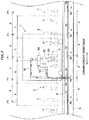
- a spinning frame 1 (yarn winding machine) shown in FIG. 1 includes a plurality of spinning units 2 (winding units) that is arranged side-by-side along a predetermined arrangement direction (horizontal direction in FIG. 1 ), a yarn joining cart 3 (service cart) that is movable in the arrangement direction, a blower box 4 arranged on one side in the arrangement direction, and a motor box 5 arranged on the other side in the arrangement direction.
- Each of the spinning units 2 spins, by using a spinning device 20, a fiber bundle T conveyed from a drafting device 10 and forms a spun yarn Y.
- a winding device 40 winds the spun yarn Y on a bobbin B thereby forming a package P.
- the yarn joining cart 3 moves to that spinning unit 2 and performs yarn joining.
- a suction device 6 that supplies a negative pressure to the spinning unit 2 and the yarn joining cart 3, and the like are arranged in the blower box 4.
- a not-shown driving source that is shared among all the spinning units 2, and the like are arranged in the motor box 5. However, a separate driving source can be arranged for each of the spinning units 2.
- the side on which a yarn path is present when seen from the yarn joining cart 3 is defined as a front side (left side in FIGS. 2 to 4 ) while the opposite side of this side is defined as a back side (right side in FIGS. 2 to 4 ).
- the spinning unit 2 includes the drafting device 10, the spinning device 20, a yarn accumulating device 30, and the winding device 40 as main structural components, and these structural components are arranged in this order from an upstream side to a downstream side in a traveling direction (hereinafter, "yarn traveling direction") of the fiber bundle T or the yarn Y.
- the drafting device 10 is arranged near a top edge of a frame 7 of the spinning frame 1.
- the drafting device 10 includes four drafting rollers 11 to 14, that is, a back roller 11, a third roller 12, a middle roller 13, and a front roller 14, arranged in this order from the upstream side.
- An apron belt 15 made of rubber is stretched over the middle roller 13.
- Each of the drafting rollers 11 to 14 is rotationally driven at a predetermined rotational speed.
- the drafting device 10 also includes opposed rollers 11a to 14a that are arranged so as to oppose a corresponding roller among the drafting rollers 11 to 14.
- a sliver S is a raw material of the fiber bundle T.
- the drafting device 10 transports the sliver S by sandwiching between the rotating drafting rollers 11 to 14 and the opposed rollers 11a to 14a, which oppose the drafting rollers, and pulling (drafting) so that the sliver S has a predetermined width thereby forming the fiber bundle T.
- the spinning device 20 is arranged immediate downstream of the front roller 14.
- the spinning device 20 spins the fiber bundle T by twisting the fiber bundle T supplied thereto from the drafting device 10 thereby forming the yarn Y.
- an air device that twists the fiber bundle T by using a swirling air current is used as the spinning device 20; however, a device of some other type can be used.
- the yarn accumulating device 30 is arranged between the spinning device 20 and the winding device 40 in the yarn traveling direction.
- the yarn accumulating device 30 includes an accumulating roller 31, a yarn hooking member 32, and a motor 33.
- the accumulating roller 31 is configured so that the yarn Y of a predetermined amount can be wound around an outer peripheral surface thereof thereby temporarily accumulating the yarn Y.
- the accumulating roller 31 is rotationally driven by the motor 33.
- the yarn hooking member 32 capable of hooking the yarn Y is attached to a downstream end of the accumulating roller 31.
- the yarn Y is accumulated on the accumulating roller 31 when the yarn hooking member 32 that has hooked the yarn Y rotates integrally with the accumulating roller 31.
- the yarn accumulating device 30 has the following functions: to apply a tension to the yarn Y to pull the yarn Y from the spinning device 20, to prevent slackening of the yarn Y by temporarily accumulating the yarn Y fed out from the spinning device 20 when the yarn joining cart 3 performs the yarn joining operation, and to prevent variations in the tension of the yarn Y on the winding device 40 side from being conveyed to the spinning device 20 side.
- a pair of pulling rollers such as delivery rollers, can be arranged between the spinning device 20 and the yarn accumulating device 30, and the yarn Y can be pulled from the spinning device 20 by using those pulling rollers. When this configuration is adopted, the yarn accumulating device 30 can be omitted.
- a guide member 34 that guides the yarn Y pulled from the yarn accumulating device 30 to the downstream side is provided downstream of the yarn accumulating device 30.
- the guide member 34 guides the yarn Y pulled from the accumulating roller 31 such that the yarn Y passes on a line that extends from a rotation axis of the accumulating roller 31.
- a yarn monitoring device 21 that monitors a quality of the yarn Y is arranged between the spinning device 20 and the yarn accumulating device 30 in the yarn traveling direction.
- the yarn monitoring device 21 monitors a thickness of the traveling yarn Y with a not-shown optical sensor.
- the yarn monitoring device 21 detects a yarn defect (a portion in which the yarn Y has an abnormal thickness and the like) of the yarn Y.
- the sensor of the yarn monitoring device 21 is not limited to the optical sensor; it can be, for example, an electrostatic capacitance sensor.
- the yarn monitoring device 21 can also detect a foreign substance included in the yarn Y as the yarn defect.
- the spinning unit 2 stops the supply of the air to the spinning device 20 to stop the formation of the yarn Y thereby cutting the yarn Y.
- a cutter can be arranged near the yarn monitoring device 21 and the yarn Y can be cut with the cutter.
- the winding device 40 is arranged downstream of the yarn accumulating device 30.
- the winding device 40 winds the yarn Y on the bobbin B while traversing the yarn Y thereby forming the package P.
- the winding device 40 includes a cradle arm 41, a winding drum 42, and a traversing device 43.
- the cradle arm 41 is pivotably supported on a support shaft 44.
- the cradle arm 41 rotatably supports the bobbin B (the package P) on which the yarn Y is wound.
- the winding drum 42 is rotationally driven in a predetermined direction at a constant rotational speed.
- the cradle arm 41 can cause the outer peripheral surface of the bobbin B (the package P) to contact with or separate from the winding drum 42.
- the bobbin B (the package P) can be caused to rotate in a winding direction whereby the yarn Y is wound on the outer peripheral surface of the bobbin B (the package P).
- the traversing device 43 includes a traversing guide 45 that can guide the yarn Y.
- the traversing guide 45 is configured so as to perform, by a not-shown driving source, a reciprocating movement in a direction parallel to an axial direction of the winding drum 42. By reciprocatively driving the traversing guide 45 while rotating the winding drum 42, it is possible to wind the yarn Y on the package P while traversing the yarn Y.
- a traversing groove can be formed on the winding drum 42 so that the spinning unit 2 can traverse the yarn Y by using only the winding drum 42 without the traversing device 43.
- the yarn joining cart 3 is explained below. As shown in FIG. 1 , a rail 8 that extends in the arrangement direction is arranged in the spinning frame 1.
- the yarn joining cart 3 has wheels 50 that move on the rail 8 and a motor 51 (see FIG. 5 ) that drives the wheels 50. Accordingly, the yarn joining cart 3 can travel freely in the arrangement direction of the spinning units 2. When a yarn breakage or a yarn cut occurs in a certain spinning unit 2, the yarn joining cart 3 moves to that spinning unit 2, and performs the yarn joining of the yarn Y that has become discontinuous between the spinning device 20 and the winding device 40.
- the yarn joining cart 3 includes a yarn joining device 52, a suction pipe 53 (suction member), a suction mouth 54 (suction member), and the like.
- the yarn joining device 52 performs the yarn joining of the yarn (upper yarn) Y from the spinning device 20 guided by the suction pipe 53 and the yarn (lower yarn) Y from the winding device 40 guided by the suction mouth 54.
- a splicer that applies a twist to yarn ends of the upper yarn Y and the lower yarn Y by a swirling air current thereby forming a joint is used as the yarn joining device 52.
- the yarn joining device 52 is not limited to the splicer and, for example, can be a knotter that joins the upper yarn Y and the lower yarn Y.
- the yarn joining cart 3 can be a piecer that guides the lower yarn Y to the spinning device 20 and connects the yarns Y by restarting the spinning in the spinning device 20.
- the suction pipe 53 is configured so as to be pivotable vertically about an axis 53a. As shown in FIG. 3 , when the suction pipe 53 is pivoted upward such that a tip of the suction pipe 53 is positioned near the downstream of the spinning device 20, the suction pipe 53 can suck and hold the upper yarn Y spun by the spinning device 20. Furthermore, as shown in FIG. 4 , when the suction pipe 53 is pivoted downward with the upper yarn Y spun by the spinning device 20 sucked and held thereby, the suction pipe 53 can guide the upper yarn Y to the yarn joining device 52.
- the suction mouth 54 is configured so as to be pivotable vertically around an axis 54a. As shown in FIG. 3 , when the suction mouth 54 is pivoted downward such that a tip of the suction mouth 54 is positioned near the outer peripheral surface of the package P, the suction mouth 54 can suck and hold the lower yarn Y pulled from the package P. Furthermore, as shown in FIG. 4 , when the suction mouth 54 is pivoted upward with the lower yarn Y pulled from the package P sucked and held thereby, the suction mouth 54 can guide the lower yarn Y to the yarn joining device 52.
- the yarn joining cart 3 includes a reverse rotation roller 55 that rotates the package P in a pulling direction that is a reverse direction of the winding direction.
- the reverse rotation roller 55 is attached to a linking mechanism 56.
- the reverse rotation roller 55 is rotationally driven by a reverse rotation motor 57 (see FIG. 5 ) in a reverse direction of the rotation direction of the winding drum 42.
- the linking mechanism 56 is expanded and contracted by an air cylinder 58. When the linking mechanism 56 is expanded by the air cylinder 58, as shown in FIG. 3 , the reverse rotation roller 55 contacts the package P that has been separated from the winding drum 42 thereby rotating the package P in the pulling direction. While rotating the package P in the pulling direction, the yarn end of the lower yarn Y that has been wound on the package P can be sucked with the suction mouth 54, and the yarn end can be guided to the yarn joining device 52.
- the spinning frame 1 includes a central control section 1a.
- the central control section 1a is configured so as to exchange electric signals between the spinning units 2 and the yarn joining cart 3.
- the central control section 1a is capable of centrally managing and controlling the spinning units 2 and the yarn joining cart 3.
- Each of the spinning units 2 includes a unit control section 2a that controls operations of the components of the spinning unit 2 and that can communicate with the central control section 1a.
- one unit control section 2a can be arranged for a predetermined number of the spinning units 2.
- the yarn joining cart 3 includes a cart control section 3a that controls operations of the components of the yarn joining cart 3 and that can communicate with the central control section 1a.
- one yarn joining cart 3 can perform the yarn joining operation with respect to 40 spinning units 2 arranged in a service region R, by moving in the service region R.
- a unit number among the numbers Y1 to Y40 is assigned to each of the spinning units 2.
- the number of the spinning units 2 arranged in the service region R can be equal to or more than 1 and equal to or less than 39, or equal to or more than 41 and equal to or less than 100.
- the unit control section 2a of each of the spinning units 2 can transmit a yarn joining request signal containing information about its own unit number to the central control section 1a.
- the central control section 1a transmits to the cart control section 3a the yarn joining request signal received from the spinning unit 2. Accordingly, the yarn joining cart 3 starts the yarn joining operation.
- the yarn joining request signal can be transmitted directly from the unit control section 2a to the cart control section 3a.
- each hollow triangle P1 shown in FIG. 6 represents a service position at which the yarn joining cart 3 performs the yarn joining operation in the corresponding spinning unit 2.
- a plurality of service positions P1 are arranged in the spinning frame 1.
- Each solid triangle P2 represents a standby position at which the yarn joining cart 3 stands by in a stop state without traveling and does not perform the yarn joining operation in any of the spinning units 2.
- Each of the standby positions P2 is set at the center of two adjacent service positions P1 in the arrangement direction.
- a position of the yarn joining cart 3 will be shown at a center of the yarn joining cart 3 in the arrangement direction (for example, FIG. 6 shows a state in which the yarn joining cart 3 has stopped at the service position P1 of the spinning unit 2 having the unit number Y16).
- the spinning frame 1 includes a discharge duct 9 extending along the arrangement direction.
- One end of the discharge duct 9 is connected to the suction device 6.
- a pipe-shaped connection tube 59 that projects downward from a lower side of a frame of the yarn joining cart 3 is provided in the yarn joining cart 3.
- a bottom end of the connection tube 59 is separated from a top surface of the discharge duct 9 by a small distance.
- the bottom end of the connection tube 59 may be touching the top surface of the discharge duct 9.
- the connection tube 59 can be connected to an opening 9a formed on the top surface of the discharge duct 9.
- connection tube 59 of the yarn joining cart 3 is connected to the suction pipe 53 via a suction tube 61, and the connection tube 59 is connected to the suction mouth 54 via a suction tube 62.
- a plurality of openings 9a is formed on the top surface of the discharge duct 9 in the arrangement direction at a pitch p that is the same as an arrangement pitch p of the spinning units 2.
- the yarn joining cart 3 moves to the service position P1 corresponding to the spinning unit 2 and stops (an example in which the yarn joining operation is performed in the central spinning unit 2 is shown in FIG. 7 ).
- the yarn joining cart 3 is positioned at the service position P1
- the yarn joining device 52 is positioned at a position at which the yarn joining device 52 overlaps, when seeing from the front, with a yarn path in the spinning unit 2 in which the yarn joining operation is to be performed, and the connection tube 59 is connected to the opening 9a provided corresponding to this spinning unit 2. Accordingly, the yarn joining operation by the yarn joining cart 3 can be performed.
- the service positions P1 are arranged in the arrangement direction at the pitch p that is the same as the arrangement pitch p of the spinning units 2 so that the yarn joining cart 3 can perform the yarn joining operation in each of the spinning units 2.
- the yarn joining cart 3 moves to the standby position P2 and stops.
- the standby position P2 is located at the center of two adjacent service positions P1 in the arrangement direction.
- the standby positions P2 are arranged in the arrangement direction at the pitch p that is the same as the arrangement pitch p of the spinning units 2.
- the connection tube 59 is positioned at a position (a central location between the two adjacent openings 9a) that does not match with the opening 9a. Therefore, when the yarn joining cart 3 is positioned at the standby position P2, the yarn joining operation cannot be performed in the spinning unit 2 as the connection tube 59 is not connected to the discharge duct 9.
- a plurality of shutters 70 is arranged on the top surface of the discharge duct 9 such that each of the shutters 70 opens / closes a corresponding one of the openings 9a.
- each of the shutters 70 according to the present embodiment is a thin, cross-shaped member having a contour obtained by combining a plurality of circular members.
- the shutter 70 includes a central part 70a and four plates 70b that project outward in a radial direction from the central part 70a.
- the four plates 70b are arranged at an equal interval of 90 degrees in a circumferential direction.
- the opening 9a is closed when any of the plates 70b covers the opening 9a.
- an open part 70c that is concave.
- the opening 9a is opened when the open part 70c overlaps with the opening 9a.
- the central part 70a is attached to the top surface of discharge duct 9 via a support shaft 71.
- the shutter 70 is rotatable about the support shaft 71.
- the opening 9a is closed by the shutter 70.
- the yarn joining cart 3 is being moved to the service position P1 (moving the connection tube 59 to a position of the opening 9a), as shown in FIG. 9B , the lower end of the connection tube 59 contacts a border of the plate 70b, rotates the shutter 70, and enters into the open part 70c.
- the connection tube 59 is exactly above the opening 9a and positioned in the open part 70c. Accordingly, the connection tube 59 can be connected to the discharge duct 9 via the opening 9a.
- the shutter 70 is configured such that, when the yarn joining cart 3 moves to the service position P1, the connection tube 59 contacts the shutter 70 and the shutter 70 is rotated to an open position at which the opening 9a is opened, and when the yarn joining cart 3 leaves the service position P1, the connection tube 59 contacts the shutter 70 and the shutter 70 is rotated to a closed position at which the shutter 70 closes the opening 9a.
- the yarn joining cart 3 that has finished the yarn joining operation at the service position P1 is controlled to wait at the same service position P1 until the next yarn joining request signal is received.
- the suction device 6 unnecessarily consumes electric power.
- the yarn joining cart 3 is stopped at the standby position P2, and the openings 9a are closed by the shutters 70. As a result, the power consumption can be reduced.
- the cart control section 3a Upon receiving the yarn joining request signal from a certain spinning unit 2, the cart control section 3a moves the yarn joining cart 3 to the service position P1 provided corresponding to the certain spinning unit 2 in which the yarn joining operation is to be performed. Then, as shown in FIG. 4 , the yarn joining device 52 performs the yarn joining of the upper yarn Y guided to the yarn joining device 52 by the suction pipe 53 and the lower yarn Y guided to the yarn joining device 52 by the suction mouth 54.
- the cart control section 3a When not receiving a yarn joining request signal from some other spinning unit 2 after the completion of the yarn joining operation, the cart control section 3a does not move the yarn joining cart 3 to the standby position P2 immediately after the completion of the yarn joining operation, instead, the cart control section 3a causes the yarn joining cart 3 to wait at the service position P1 for a predetermined standby time (for example, between 30 seconds and 60 seconds).
- the cart control section 3a moves the yarn joining cart 3 from the current service position P1 to the standby position P2 that is adjacent to the current service position P1. For example, as shown in FIG. 6 , when the standby position P2 adjacent to the current service position P1 exists on either side in the arrangement direction, the yarn joining cart 3 can be moved to the standby position P2 that is adjacent but that is toward the center (right side in FIG. 6 ) of the service region R of the yarn joining cart 3.
- the cart control section 3a causes the yarn joining cart 3 to wait at the standby position P2 until a yarn joining request signal is received next. When a yarn joining request signal is received newly, the cart control section 3a moves the yarn joining cart 3 to the service position P1 provided corresponding to the spinning unit 2 to perform the yarn joining operation, and causes the yarn joining cart 3 to perform the yarn joining operation.
- the cart control section 3a When a yarn joining request signal has already been received from some other spinning unit 2 before completion of the yarn joining operation, the cart control section 3a does not stop the yarn joining cart 3 at any of the standby positions P2 after the completion of the yarn joining operation but directly moves the yarn joining cart 3 to the service position P1 provided corresponding to the spinning unit 2 that sent the yarn joining request signal.
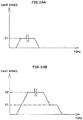
- two speed patterns are prepared for moving the yarn joining cart 3.
- a first speed pattern shown in FIG. 10A after increasing a moving speed of the yarn joining cart 3 by a certain acceleration to a maximum speed V1 (first maximum speed), the speed V1 is maintained.
- the moving speed of the yarn joining cart 3 is reduced by a certain deceleration to stop the yarn joining cart 3.
- a second speed pattern shown in FIG. 10B after increasing the moving speed of the yarn joining cart 3 by a certain acceleration to a maximum speed V2 (second maximum speed) that is higher than the speed V1, the speed V2 is maintained.
- the moving speed of the yarn joining cart 3 is first reduced by a certain deceleration so that the speed reaches the speed V1, the speed V1 is maintained for a certain time, thereafter, the speed is reduced by a certain deceleration to stop the yarn joining cart 3.
- the speed of the yarn joining cart 3 may be reduced from the speed V2 directly to zero.
- the cart control section 3a determines which speed pattern is to be used.
- the time for which the maximum speed V1 is to be maintained in the first speed pattern, or the time for which the maximum speed V2 is to be maintained in the second speed pattern is calculated depending on an actual moving distance.
- the same acceleration and the same deceleration are used in both the first speed pattern and the second speed pattern.
- the acceleration and the deceleration can be set different in the first speed pattern and the second speed pattern.
- the low-speed first speed pattern is used when moving the yarn joining cart 3 from a certain service position P1 to the service position P1 that is adjacent to the certain service position P1 (when the moving distance is p).
- the high-speed second speed pattern is used when moving the yarn joining cart 3 from a certain service position P1 to the service position P1 that is two or more service positions away from the certain service position P1 (when the moving distance is px2 or more).
- the low-speed first speed pattern is used when moving the yarn joining cart 3 from a certain service position P1 to the standby position P2 adjacent to the certain service position P1 (when the moving distance is p/2).
- the cart control section 3a can calculate a required time for the movement based on a moving distance and a rotation number (rpm) of the motor 51, and the like. Specifically, first, the cart control section 3a calculates the moving distance of the yarn joining cart 3. Then, the cart control section 3a selects the first speed pattern when the moving distance is shorter than or equal to p, and selects the second speed pattern when the moving distances is longer than p. After selecting the appropriate speed pattern, the cart control section 3a calculates, based on the moving distance, the time for which the maximum speed V1 or V2 is to be maintained, and calculates the required time for the movement by adding thus calculated time to a fixed acceleration time and a fixed deceleration time.
- rpm rotation number
- the cart control section 3a can store a table that contains a correspondence of required times and moving distances beforehand, and acquire the required time from this table as needed.
- the cart control section 3a determines whether the required time has elapsed after the start of the movement of the yarn joining cart 3, and stops the yarn joining cart 3 when the required time has elapsed thereby positioning the yarn joining cart 3 at a desired position.
- the yarn joining cart 3 (service cart) is configured such that the yarn joining cart 3 can stop at the service position P1 at which the connection tube 59 can be connected to the opening 9a formed in the discharge duct 9 and at which a service can be provided to the spinning unit 2 (winding unit), and can stop at the standby position P2 that is located between the two adjacent service positions P1 and at which the connection tube 59 cannot be connected to the opening 9a. Therefore, by stopping the yarn joining cart 3 at the standby position P2 when not performing the yarn joining operation in the spinning unit 2, the opening 9a to which the connection tube 59 is not connected can be closed with the shutter 70. Accordingly, the power consumption of the suction device 6 can be reduced.
- one approach could be to provide some kind of opening and shutting valve to the connection tube 59.
- the number of parts will increase leading to increased costs and increased man-hours in the maintenance.
- the present embodiment has no such drawback.
- the yarn joining cart 3 moves to and stops at the standby position P2. As a result, the power consumption of the suction device 6 after the completion of the yarn joining operation can be reduced.
- the yarn joining cart 3 moves to the standby position P2 that is adjacent to the service position P1. As a result, the yarn joining cart 3 can quickly move to the standby position P2.
- the yarn joining cart 3 can perform the yarn joining operation in a plurality of the spinning units 2 arranged in the predetermined service region R. After completion of the yarn joining operation in the spinning unit 2 at the service position P1, the yarn joining cart 3 moves to the standby position P2 that is nearer to the center of the service region R than the service position P1. As a result, the distance between the yarn joining cart 3 and most of the spinning units 2 can be reduced. Accordingly, when there is a service request from one of those spinning units 2 next, the time taken by the yarn joining cart 3 for the movement can be shortened.
- the cart control section 3a (control section) that can control the operation of the yarn joining cart 3.
- a work efficiency and the like of the yarn joining cart 3 can be improved by causing the cart control section 3a to make various kinds of decisions and determinations.
- the cart control section 3a determines whether the required time for the movement has elapsed, and stops the yarn joining cart 3 if the required time has elapsed. Accordingly, the yarn joining cart 3 can be stopped at the standby position P2 without providing a sensor and the like in the yarn joining cart 3 to recognize the standby position P2.
- the cart control section 3a can control the movement of the yarn joining cart 3 in accordance with the first speed pattern in which the yarn joining cart 3 can be moved from a certain service position P1 to another service position P1 adjacent to the certain service position P1 and the second speed pattern in which the maximum speed is faster than the maximum speed in the first speed pattern and in which the yarn joining cart 3 can be moved from the certain service position P1 to another service position P1 that is positioned two or more service positions P1 away from the certain service position P1.
- the cart control section 3a moves the yarn joining cart 3 by using the first speed pattern.
- the yarn joining cart 3 can be accurately stopped at the standby position P2.
- the cart control section 3a when the cart control section 3a receives a yarn joining request signal (service request signal) from a certain spinning unit 2 while the yarn joining cart 3 is stopping at the standby position P2, the yarn joining cart 3 is moved from the standby position P2 to the service position P1 at which the yarn joining cart 3 can perform the yarn joining operation in the spinning unit 2 that sent the yarn joining request signal.
- the yarn joining operation can be quickly started in the spinning unit 2 that sent the yarn joining request signal.
- the cart control section 3a when a yarn joining request signal has been received from some other spinning unit 2 before completion of the yarn joining operation in a certain spinning unit 2 at the service position P1, the cart control section 3a does not stop the yarn joining cart 3 at any of the standby positions P2 after completion of the yarn joining operation but directly moves the yarn joining cart 3 to the service position P1 for performing the yarn joining operation provided corresponding to the spinning unit 2 that sent the yarn joining request signal.
- the service request signal has been received before completion of the yarn joining operation, by directly moving the yarn joining cart 3 from the current service position P1 to the next service position P1 without stopping at the standby position P2, the yarn joining operation can be started quickly.
- the yarn joining cart 3 includes the yarn joining device 52 that performs the yarn joining operation. Moreover, the cart control section 3a moves the yarn joining cart 3 to the standby position P2 after completion of the yarn joining operation in the spinning unit 2 at the service position P1. As a result, the power consumption of the suction device 6 after completion of the yarn joining operation can be reduced.
- the cart control section 3a moves the yarn joining cart 3 to the standby position P2 after a predetermined standby time has elapsed after the completion of the yarn joining operation in the spinning unit 2 at the service position P1.
- a yarn breakage is easy to occur immediately after the completion of the yarn joining operation. Therefore, by stopping the yarn joining cart 3 at the same service position P1 just for the predetermined standby time after the completion of the yarn joining operation, the yarn joining operation can be performed immediately in case a yarn breakage occurs.
- the shutter 70 when the yarn joining cart 3 moves to the service position P1, by contact with the connection tube 59, the shutter 70 is switched to the open position at which the opening 9a is open, and when the yarn joining cart 3 leaves the service position P1, by contact with the connection tube 59, the shutter 70 is switched to the closed position at which the shutter closes the opening 9a.
- no special mechanism and electric parts are required to operate the shutter 70.
- one yarn joining cart 3 performs the yarn joining operation in all the spinning units 2; however, a plurality of the yarn joining carts 3 can be arranged to perform the yarn joining operation.
- An example in which the yarn joining operation is performed in 40 spinning units 2 (unit numbers Y1 to Y40) with two yarn joining carts 3 (3A, 3B) is explained below by referring to FIG. 11 .
- FIG. 11 for simplicity, it is shown that the yarn joining carts 3A and 3B travel on different rails; however, in a real situation, both the yarn joining carts 3A and 3B travel on a common rail.
- a service region RA is a region in which the yarn joining cart 3A can travel.
- the spinning units 2 having the unit numbers Y1 to Y24 are arranged in the service region RA.
- a service region RB is a region in which the yarn joining cart 3B can travel.
- the spinning units 2 having the unit numbers Y17 to Y40 are arranged in the service region RB.
- a service region RC is a region of overlap of the service region RA and the service region RB. That is, the service region RC is the region in which both the yarn joining carts 3A and 3B can travel, and the spinning units 2 having the unit numbers Y17 to Y24 are arranged in the service region RC.
- the central control section 1a transmits the yarn joining request signal to the yarn joining cart 3 that can perform the yarn joining operation in that spinning unit 2. Specifically, when the yarn joining request signal is sent from one of the spinning units 2 having the unit numbers Y1 to Y16, the yarn joining request signal is transmitted to the yarn joining cart 3A. In contrast, when the yarn joining request signal is sent from one of the spinning units 2 having the unit numbers Y25 to Y40, the yarn joining request signal is transmitted to the yarn joining cart 3B.
- the yarn joining request signal is sent from one of the spinning units 2 having the unit numbers Y17 to Y24, for example, the yarn joining request signal is transmitted to the yarn joining cart 3A (or 3B) positioned nearer the spinning unit 2 that sent the yarn joining request signal.
- the cart control section 3a of the yarn joining cart 3A (or 3B) that received the yarn joining request signal moves the yarn joining cart 3A (or 3B) to the service position P1 provided corresponding to the spinning unit 2 for the yarn joining operation.
- the cart control section 3a moves the yarn joining cart 3 from the service position P1 to the standby position P2 that is adjacent to the service position P1.
- the yarn joining cart 3 is not immediately moved to the standby position P2 after the completion of the yarn joining operation, instead, the yarn joining cart 3 can be caused to wait at the service position P1 for the predetermined standby time.
- the yarn joining cart 3 after finishing the yarn joining operation at the service position P1, the yarn joining cart 3 is moved to the standby position P2 that is adjacent to the current service position P1.
- the yarn joining cart 3 may be moved to some other standby position P2 that is not adjacent to the current service position P1.
- the yarn joining cart 3 can be moved to the standby position P2 that is nearest to the center of the service region R.
- the yarn joining cart 3 when the standby position P2 adjacent to the current service position P1 exists on either side in the arrangement direction, the yarn joining cart 3 is moved after the completion of the yarn joining operation at the service position P1 to the standby position P2 that is adjacent but toward the center of the service region R of the yarn joining cart 3.
- the yarn joining cart 3 can be moved to the standby position P2 that is adjacent but located in the opposite direction of the center of the service region R.
- the cart control section 3a can determine the standby position P2 at which the yarn joining cart 3 is to be stopped based on a service occurrence frequency in each of the spinning units 2. With this arrangement, the yarn joining cart 3 can be caused to wait at the standby position P2 near the spinning unit 2 having a high service occurrence frequency, whereby the work efficiency can be improved. For example, after completion of the yarn joining operation in the spinning unit 2 at the service position P1, the cart control section 3a can move the yarn joining cart 3 to the standby position P2 that is adjacent to the service position P1 for providing the service to the spinning unit 2 having the highest service occurrence frequency. With this arrangement, the yarn joining cart 3 can be caused to wait at the standby position P2 near the spinning unit 2 having the highest service occurrence frequency, whereby the work efficiency can be further improved.
- the yarn joining cart 3 is moved based on the required time acquired beforehand by the cart control section 3a.
- a position indicator that indicates the service position P1 and / or the standby position P2 can be provided in the spinning frame 1, and a detecting section that detects the position indicator can be provided in the yarn joining cart 3.
- a position indicating member 80 is arranged above the yarn joining cart 3 along the arrangement direction.
- the position indicating member 80 includes a plurality of service position indicators 81 that indicates the positions of the service positions P1 and a plurality of standby position indicators 82 that indicates the positions of the standby positions P2.
- a detecting section 63 including a proximity sensor and the like adapted to detect the service position indicators 81 and the standby position indicators 82 is arranged at an upper end of the yarn joining cart 3.
- the cart control section 3a can control the movement of the yarn joining cart 3 based on a detection signal output from the detecting section 63. Accordingly, the yarn joining cart 3 can be accurately stopped at the desired service position P1 and / or the standby position P2.
- the standby position P2 is set at the center of the two adjacent service positions P1.
- the standby position P2 can be anywhere and not limited to the center of the two adjacent service positions P1.
- the specific structure of the shutter 70 is not limited to the one explained in the above embodiment.
- an electric opening and shutting valve may be adopted as the shutter 70.
- the movement of the yarn joining cart 3 is controlled based on the two speed patterns; however, the speed pattern to be used can be only one or can be three or more.
- the device to which the present invention can be applied is not limited to the spinning frame 1.
- the doffing cart can be caused to wait at a standby position between a service position and another service position.
- a yarn winding machine includes a plurality of winding units arranged in an arrangement direction; a discharge duct extending along the arrangement direction and in which a plurality of openings are formed along the arrangement direction; a plurality of shutters adapted to respectively open or close the openings; a service cart including a connection tube adapted to be connected to the discharge duct via one of the openings, the service cart being movable in the arrangement direction; and a suction device connected to the discharge duct.
- the service cart is able to stop at a service position and a standby position.
- the service position is a position at which the connection tube is connected to one of the openings and at which the service cart can perform a service in one of the winding units.
- the standby position is a position between two adjacent service positions and at which the connection tube is not connected to the opening.
- the service cart can move from a certain service position at which the service cart performs the service in a certain winding unit to the standby position after completion of the service in the certain winding unit.
- the service cart can move from a certain service position at which the service cart performs the service in a certain winding unit to the standby position adjacent to the certain service position after completion of the service in the certain winding unit.
- the service cart can quickly move to the standby position.
- the service cart can perform the service in a plurality of the winding units within a predetermined service region, and after completion of the service in a certain winding unit at a certain service position, the service cart can move to the standby position positioned nearer to a center of the service region than the certain service position.
- the distance between the service cart and most of the winding units can be reduced. Accordingly, when there is a service request from one of those winding units next, the time taken by the service cart for the movement can be shortened.
- the above yarn winding machine can further include a control section adapted to control operation of the service cart.
- a work efficiency and the like of the service cart can be improved by causing the control section to make various kinds of decisions and determinations.
- control section can determine the standby position for stopping the service cart in accordance with a service occurrence frequency of each of the winding units.
- the service cart can be caused to wait, for example, at the standby position near the winding unit having the highest service occurrence frequency, whereby the work efficiency can be improved.
- control section can control the service cart to move to the standby position adjacent to a different service position for performing service in a different winding unit having the highest service occurrence frequency.
- the control section when moving the service cart from a certain service position to the standby position, the control section can determine whether a required time for such movement has elapsed, and when the required time has elapsed, the control section can control the service cart to stop.
- the service cart can be stopped at the standby position without providing a sensor and the like in the service cart to recognize the standby position.
- the control section can control movement of the service cart in accordance with a first speed pattern and a second speed pattern.
- the first speed pattern can be a speed pattern in which the service cart moves from a certain service position to a different service position adjacent to the certain service position at a speed that is equal to or lower than a first maximum speed
- the second speed pattern can be a speed pattern in which the service cart moves from a certain service position to a different service position positioned at least two service positions away from the certain service position at a speed that is equal to or lower than a second maximum speed that is higher than the first maximum speed.
- the service cart can be accurately stopped at the standby position.
- the control section upon receiving a service request signal from a certain winding unit while the service cart is stopping at the standby position, the control section can control the service cart to move from the standby position to a certain service position at which the service can be performed in the certain winding unit that has issued the service request signal.
- the service can be quickly started in the winding unit that issued the service request signal.
- the control section upon completion of the service in a certain winding unit at a certain service position, when the control section has already received a new service request signal from a different winding unit different from the certain winding unit, the control section can control the service cart to move to a different service position at which the service can be performed in the different winding unit without stopping at the standby position after completion of the service in the certain winding unit.
- the service cart can include a yarn joining device adapted to perform a yarn joining operation. After completion of the yarn joining operation in a certain winding unit at a certain service position, the control section can move the service cart to the standby position.
- control section can move the service cart to the standby position.
- connection tube when the service cart moves to a certain service position, the connection tube can contact a corresponding shutter and the shutter can be switched to an open position to open the opening, and when the service cart moves away from the certain service position, the connection tube can contact the shutter and the shutter can be switched to a closed position to close the opening.
- the above yarn winding machine can further include a standby position indicator adapted to indicate the standby position.
- the service cart can include a detecting section adapted to detect the standby position indicator.
- the service cart can be accurately stopped at the standby position.
- the winding units are arranged at a predetermined arrangement pitch in the arrangement direction, and a distance between the service position and the standby position adjacent to the service position is shorter than the arrangement pitch.
Abstract
A service cart (3) is configured such that the service cart (3) can stop at a service position (P1) at which a connection tube (59) can be connected to an opening (9a) formed in a discharge duct (9) and at which a service can be performed in a winding unit (2), and can stop at a standby position (P2) that is located between two adjacent service positions (P1) and at which the connection tube (59) cannot be connected to the opening (9a).
Description
- The present invention relates to a yarn winding machine.
- For example, Japanese Patent Application Laid-Open No.
2014-9052 - Conventionally, after the service cart has provided the service to a certain winding unit at a position (hereinafter, "service position") at which the connection tube has been connected to the corresponding opening, until a new service request is received from another winding unit, the service cart will remain on standby at the service position. However, for example, because suction members such as a suction mouth and a suction pipe connected to the connection tube are open to the atmosphere, while the service cart is stopping at the service position, air flows in these suction members even if no service is being provided. Thus, the suction device connected to the discharge duct unnecessarily consumes electric power.
- An object of the present invention is to reduce the electric power consumption of the suction device that supplies a negative pressure to the service cart.
- This object is achieved by a yarn winding machine according to the independent claim.
- A yarn winding machine according to one aspect of the present invention includes a plurality of winding units arranged in an arrangement direction; a discharge duct extending along the arrangement direction and in which a plurality of openings are formed along the arrangement direction; a plurality of shutters adapted to respectively open or close the openings; a service cart including a connection tube adapted to be connected to the discharge duct via one of the openings, the service cart being movable in the arrangement direction; and a suction device connected to the discharge duct. The service cart is able to stop at a service position and a standby position. The service position is a position at which the connection tube is connected to one of the openings and at which the service cart can perform a service in one of the winding units. The standby position is a position between two adjacent service positions and at which the connection tube is not connected to the opening.
-
-
FIG. 1 is a front view indicating an overall configuration of a spinning frame according to an embodiment of the present invention. -
FIG. 2 is a side view of a spinning unit and a yarn joining cart. -
FIG. 3 is a side view indicating a state in which a yarn has been held by suction by a suction member of the yarn joining cart. -
FIG. 4 is a side view indicating a state in which the yarn is being guided to a yarn joining device by the suction member of the yarn joining cart. -
FIG. 5 is a block diagram of an electrical configuration of the spinning frame. -
FIG. 6 is a schematic diagram of a service region of the yarn joining cart. -
FIG. 7 is a front view of a state in which the yarn joining cart is at a service position. -
FIG. 8 is a front view of a state in which the yarn joining cart is at a standby position. -
FIGS. 9A, 9B, and 9C are top views of a shutter. -
FIGS. 10A and 10B show graphs of a speed pattern of the yarn joining cart. -
FIG. 11 is a schematic diagram of a service region when two yarn joining carts are provided. -
FIG. 12 is a front view of an example of a position indicating member. - Exemplary embodiments of a spinning frame according to the present invention are explained in detail below with reference to the accompanying drawings. A spinning frame 1 (yarn winding machine) shown in
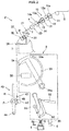
FIG. 1 includes a plurality of spinning units 2 (winding units) that is arranged side-by-side along a predetermined arrangement direction (horizontal direction inFIG. 1 ), a yarn joining cart 3 (service cart) that is movable in the arrangement direction, ablower box 4 arranged on one side in the arrangement direction, and amotor box 5 arranged on the other side in the arrangement direction. - Each of the
spinning units 2 spins, by using aspinning device 20, a fiber bundle T conveyed from adrafting device 10 and forms a spun yarn Y. Awinding device 40 winds the spun yarn Y on a bobbin B thereby forming a package P. When a yarn breakage or a yarn cut occurs in acertain spinning unit 2, theyarn joining cart 3 moves to thatspinning unit 2 and performs yarn joining. Asuction device 6 that supplies a negative pressure to thespinning unit 2 and theyarn joining cart 3, and the like are arranged in theblower box 4. A not-shown driving source that is shared among all thespinning units 2, and the like are arranged in themotor box 5. However, a separate driving source can be arranged for each of thespinning units 2. - In the present specification, the side on which a yarn path is present when seen from the
yarn joining cart 3 is defined as a front side (left side inFIGS. 2 to 4 ) while the opposite side of this side is defined as a back side (right side inFIGS. 2 to 4 ). - The
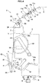
spinning unit 2 includes thedrafting device 10, thespinning device 20, ayarn accumulating device 30, and thewinding device 40 as main structural components, and these structural components are arranged in this order from an upstream side to a downstream side in a traveling direction (hereinafter, "yarn traveling direction") of the fiber bundle T or the yarn Y. - The
drafting device 10 is arranged near a top edge of aframe 7 of the spinning frame 1. Thedrafting device 10 includes fourdrafting rollers 11 to 14, that is, aback roller 11, athird roller 12, amiddle roller 13, and afront roller 14, arranged in this order from the upstream side. Anapron belt 15 made of rubber is stretched over themiddle roller 13. Each of thedrafting rollers 11 to 14 is rotationally driven at a predetermined rotational speed. Thedrafting device 10 also includesopposed rollers 11a to 14a that are arranged so as to oppose a corresponding roller among thedrafting rollers 11 to 14. A sliver S is a raw material of the fiber bundle T. Thedrafting device 10 transports the sliver S by sandwiching between the rotatingdrafting rollers 11 to 14 and theopposed rollers 11a to 14a, which oppose the drafting rollers, and pulling (drafting) so that the sliver S has a predetermined width thereby forming the fiber bundle T. - The
spinning device 20 is arranged immediate downstream of thefront roller 14. Thespinning device 20 spins the fiber bundle T by twisting the fiber bundle T supplied thereto from thedrafting device 10 thereby forming the yarn Y. In the present embodiment, an air device that twists the fiber bundle T by using a swirling air current is used as thespinning device 20; however, a device of some other type can be used. - The
yarn accumulating device 30 is arranged between thespinning device 20 and thewinding device 40 in the yarn traveling direction. Theyarn accumulating device 30 includes an accumulatingroller 31, ayarn hooking member 32, and amotor 33. The accumulatingroller 31 is configured so that the yarn Y of a predetermined amount can be wound around an outer peripheral surface thereof thereby temporarily accumulating the yarn Y. The accumulatingroller 31 is rotationally driven by themotor 33. Theyarn hooking member 32 capable of hooking the yarn Y is attached to a downstream end of the accumulatingroller 31. The yarn Y is accumulated on the accumulatingroller 31 when theyarn hooking member 32 that has hooked the yarn Y rotates integrally with the accumulatingroller 31. Theyarn accumulating device 30 has the following functions: to apply a tension to the yarn Y to pull the yarn Y from thespinning device 20, to prevent slackening of the yarn Y by temporarily accumulating the yarn Y fed out from thespinning device 20 when theyarn joining cart 3 performs the yarn joining operation, and to prevent variations in the tension of the yarn Y on thewinding device 40 side from being conveyed to thespinning device 20 side. A pair of pulling rollers, such as delivery rollers, can be arranged between thespinning device 20 and theyarn accumulating device 30, and the yarn Y can be pulled from thespinning device 20 by using those pulling rollers. When this configuration is adopted, theyarn accumulating device 30 can be omitted. - A
guide member 34 that guides the yarn Y pulled from theyarn accumulating device 30 to the downstream side is provided downstream of theyarn accumulating device 30. Theguide member 34 guides the yarn Y pulled from the accumulatingroller 31 such that the yarn Y passes on a line that extends from a rotation axis of the accumulatingroller 31. - A
yarn monitoring device 21 that monitors a quality of the yarn Y is arranged between the spinningdevice 20 and theyarn accumulating device 30 in the yarn traveling direction. Theyarn monitoring device 21 monitors a thickness of the traveling yarn Y with a not-shown optical sensor. Theyarn monitoring device 21 detects a yarn defect (a portion in which the yarn Y has an abnormal thickness and the like) of the yarn Y. The sensor of theyarn monitoring device 21 is not limited to the optical sensor; it can be, for example, an electrostatic capacitance sensor. Moreover, theyarn monitoring device 21 can also detect a foreign substance included in the yarn Y as the yarn defect. - When a yarn defect is detected in the yarn Y by the
yarn monitoring device 21, thespinning unit 2 stops the supply of the air to thespinning device 20 to stop the formation of the yarn Y thereby cutting the yarn Y. A cutter can be arranged near theyarn monitoring device 21 and the yarn Y can be cut with the cutter. - The winding
device 40 is arranged downstream of theyarn accumulating device 30. The windingdevice 40 winds the yarn Y on the bobbin B while traversing the yarn Y thereby forming the package P. The windingdevice 40 includes acradle arm 41, a windingdrum 42, and atraversing device 43. - The
cradle arm 41 is pivotably supported on asupport shaft 44. Thecradle arm 41 rotatably supports the bobbin B (the package P) on which the yarn Y is wound. The windingdrum 42 is rotationally driven in a predetermined direction at a constant rotational speed. By pivoting about thesupport shaft 44, thecradle arm 41 can cause the outer peripheral surface of the bobbin B (the package P) to contact with or separate from the windingdrum 42. When the outer peripheral surface of the bobbin B (the package P) is made to contact the rotationally driven windingdrum 42, the bobbin B (the package P) can be caused to rotate in a winding direction whereby the yarn Y is wound on the outer peripheral surface of the bobbin B (the package P). - The traversing
device 43 includes a traversingguide 45 that can guide the yarn Y. The traversingguide 45 is configured so as to perform, by a not-shown driving source, a reciprocating movement in a direction parallel to an axial direction of the windingdrum 42. By reciprocatively driving the traversingguide 45 while rotating the windingdrum 42, it is possible to wind the yarn Y on the package P while traversing the yarn Y. A traversing groove can be formed on the windingdrum 42 so that thespinning unit 2 can traverse the yarn Y by using only the windingdrum 42 without the traversingdevice 43. - The
yarn joining cart 3 is explained below. As shown inFIG. 1 , arail 8 that extends in the arrangement direction is arranged in the spinning frame 1. Theyarn joining cart 3 haswheels 50 that move on therail 8 and a motor 51 (seeFIG. 5 ) that drives thewheels 50. Accordingly, theyarn joining cart 3 can travel freely in the arrangement direction of thespinning units 2. When a yarn breakage or a yarn cut occurs in acertain spinning unit 2, theyarn joining cart 3 moves to thatspinning unit 2, and performs the yarn joining of the yarn Y that has become discontinuous between the spinningdevice 20 and the windingdevice 40. - As shown in
FIGS. 2 to 4 , theyarn joining cart 3 includes ayarn joining device 52, a suction pipe 53 (suction member), a suction mouth 54 (suction member), and the like. When the yarn Y has become discontinuous between the spinningdevice 20 and the windingdevice 40, as shown inFIG. 4 , theyarn joining device 52 performs the yarn joining of the yarn (upper yarn) Y from thespinning device 20 guided by thesuction pipe 53 and the yarn (lower yarn) Y from the windingdevice 40 guided by thesuction mouth 54. In the present embodiment, a splicer that applies a twist to yarn ends of the upper yarn Y and the lower yarn Y by a swirling air current thereby forming a joint is used as theyarn joining device 52. However, theyarn joining device 52 is not limited to the splicer and, for example, can be a knotter that joins the upper yarn Y and the lower yarn Y. Theyarn joining cart 3 can be a piecer that guides the lower yarn Y to thespinning device 20 and connects the yarns Y by restarting the spinning in thespinning device 20. - The
suction pipe 53 is configured so as to be pivotable vertically about anaxis 53a. As shown inFIG. 3 , when thesuction pipe 53 is pivoted upward such that a tip of thesuction pipe 53 is positioned near the downstream of thespinning device 20, thesuction pipe 53 can suck and hold the upper yarn Y spun by thespinning device 20. Furthermore, as shown inFIG. 4 , when thesuction pipe 53 is pivoted downward with the upper yarn Y spun by thespinning device 20 sucked and held thereby, thesuction pipe 53 can guide the upper yarn Y to theyarn joining device 52. - The
suction mouth 54 is configured so as to be pivotable vertically around anaxis 54a. As shown inFIG. 3 , when thesuction mouth 54 is pivoted downward such that a tip of thesuction mouth 54 is positioned near the outer peripheral surface of the package P, thesuction mouth 54 can suck and hold the lower yarn Y pulled from the package P. Furthermore, as shown inFIG. 4 , when thesuction mouth 54 is pivoted upward with the lower yarn Y pulled from the package P sucked and held thereby, thesuction mouth 54 can guide the lower yarn Y to theyarn joining device 52. - The
yarn joining cart 3 includes areverse rotation roller 55 that rotates the package P in a pulling direction that is a reverse direction of the winding direction. Thereverse rotation roller 55 is attached to alinking mechanism 56. Thereverse rotation roller 55 is rotationally driven by a reverse rotation motor 57 (seeFIG. 5 ) in a reverse direction of the rotation direction of the windingdrum 42. The linkingmechanism 56 is expanded and contracted by anair cylinder 58. When the linkingmechanism 56 is expanded by theair cylinder 58, as shown inFIG. 3 , thereverse rotation roller 55 contacts the package P that has been separated from the windingdrum 42 thereby rotating the package P in the pulling direction. While rotating the package P in the pulling direction, the yarn end of the lower yarn Y that has been wound on the package P can be sucked with thesuction mouth 54, and the yarn end can be guided to theyarn joining device 52. - An electrical configuration of the spinning frame 1 is explained below by referring to
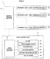
FIG. 5 . The spinning frame 1 according to the present embodiment includes acentral control section 1a. Thecentral control section 1a is configured so as to exchange electric signals between the spinningunits 2 and theyarn joining cart 3. Thecentral control section 1a is capable of centrally managing and controlling thespinning units 2 and theyarn joining cart 3. Each of thespinning units 2 includes aunit control section 2a that controls operations of the components of thespinning unit 2 and that can communicate with thecentral control section 1a. However, oneunit control section 2a can be arranged for a predetermined number of thespinning units 2. Theyarn joining cart 3 includes acart control section 3a that controls operations of the components of theyarn joining cart 3 and that can communicate with thecentral control section 1a. - In the present embodiment, as shown in
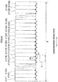
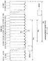
FIG. 6 , oneyarn joining cart 3 can perform the yarn joining operation with respect to 40spinning units 2 arranged in a service region R, by moving in the service region R. A unit number among the numbers Y1 to Y40 is assigned to each of thespinning units 2. The number of thespinning units 2 arranged in the service region R can be equal to or more than 1 and equal to or less than 39, or equal to or more than 41 and equal to or less than 100. Theunit control section 2a of each of thespinning units 2 can transmit a yarn joining request signal containing information about its own unit number to thecentral control section 1a. Thecentral control section 1a transmits to thecart control section 3a the yarn joining request signal received from thespinning unit 2. Accordingly, theyarn joining cart 3 starts the yarn joining operation. The yarn joining request signal can be transmitted directly from theunit control section 2a to thecart control section 3a. - Although the detailed explanation will be given later, each hollow triangle P1 shown in
FIG. 6 represents a service position at which theyarn joining cart 3 performs the yarn joining operation in thecorresponding spinning unit 2. A plurality of service positions P1 are arranged in the spinning frame 1. Each solid triangle P2 represents a standby position at which theyarn joining cart 3 stands by in a stop state without traveling and does not perform the yarn joining operation in any of thespinning units 2. Each of the standby positions P2 is set at the center of two adjacent service positions P1 in the arrangement direction. In each of the drawings, a position of theyarn joining cart 3 will be shown at a center of theyarn joining cart 3 in the arrangement direction (for example,FIG. 6 shows a state in which theyarn joining cart 3 has stopped at the service position P1 of thespinning unit 2 having the unit number Y16). - As shown in
FIG. 1 , the spinning frame 1 includes adischarge duct 9 extending along the arrangement direction. One end of thedischarge duct 9 is connected to thesuction device 6. As shown inFIGS. 2 to 4 , a pipe-shapedconnection tube 59 that projects downward from a lower side of a frame of theyarn joining cart 3 is provided in theyarn joining cart 3. In the present embodiment, a bottom end of theconnection tube 59 is separated from a top surface of thedischarge duct 9 by a small distance. However, the bottom end of theconnection tube 59 may be touching the top surface of thedischarge duct 9. Theconnection tube 59 can be connected to anopening 9a formed on the top surface of thedischarge duct 9. - The
connection tube 59 of theyarn joining cart 3 is connected to thesuction pipe 53 via asuction tube 61, and theconnection tube 59 is connected to thesuction mouth 54 via asuction tube 62. A plurality ofopenings 9a is formed on the top surface of thedischarge duct 9 in the arrangement direction at a pitch p that is the same as an arrangement pitch p of thespinning units 2. When theyarn joining cart 3 is positioned at the service position P1, theconnection tube 59 is connected to thedischarge duct 9 via one of theopenings 9a. As a result, as shown by arrows inFIG. 7 , an airflow that flows from thesuction pipe 53 and thesuction mouth 54 to thesuction device 6 via thesuction tubes connection tube 59, and thedischarge duct 9 is generated. Accordingly, a negative pressure (suction force) can be generated at the tips of thesuction pipe 53 and thesuction mouth 54. - When performing the yarn joining operation with the
yarn joining cart 3 in acertain spinning unit 2, as shown inFIG. 7 , theyarn joining cart 3 moves to the service position P1 corresponding to thespinning unit 2 and stops (an example in which the yarn joining operation is performed in thecentral spinning unit 2 is shown inFIG. 7 ). When theyarn joining cart 3 is positioned at the service position P1, theyarn joining device 52 is positioned at a position at which theyarn joining device 52 overlaps, when seeing from the front, with a yarn path in thespinning unit 2 in which the yarn joining operation is to be performed, and theconnection tube 59 is connected to theopening 9a provided corresponding to thisspinning unit 2. Accordingly, the yarn joining operation by theyarn joining cart 3 can be performed. The service positions P1 are arranged in the arrangement direction at the pitch p that is the same as the arrangement pitch p of thespinning units 2 so that theyarn joining cart 3 can perform the yarn joining operation in each of thespinning units 2. - When not performing the yarn joining operation, as shown in
FIG. 8 , theyarn joining cart 3 moves to the standby position P2 and stops. The standby position P2 is located at the center of two adjacent service positions P1 in the arrangement direction. In the same manner as the service position P1, the standby positions P2 are arranged in the arrangement direction at the pitch p that is the same as the arrangement pitch p of thespinning units 2. When theyarn joining cart 3 is positioned at the standby position P2, theconnection tube 59 is positioned at a position (a central location between the twoadjacent openings 9a) that does not match with theopening 9a. Therefore, when theyarn joining cart 3 is positioned at the standby position P2, the yarn joining operation cannot be performed in thespinning unit 2 as theconnection tube 59 is not connected to thedischarge duct 9. - A plurality of
shutters 70 is arranged on the top surface of thedischarge duct 9 such that each of theshutters 70 opens / closes a corresponding one of theopenings 9a. As shown inFIGS. 9A to 9C , each of theshutters 70 according to the present embodiment is a thin, cross-shaped member having a contour obtained by combining a plurality of circular members. Theshutter 70 includes acentral part 70a and fourplates 70b that project outward in a radial direction from thecentral part 70a. The fourplates 70b are arranged at an equal interval of 90 degrees in a circumferential direction. Theopening 9a is closed when any of theplates 70b covers theopening 9a. Between twoadjacent plates 70b in the circumferential direction is formed anopen part 70c that is concave. Theopening 9a is opened when theopen part 70c overlaps with theopening 9a. Thecentral part 70a is attached to the top surface ofdischarge duct 9 via asupport shaft 71. Theshutter 70 is rotatable about thesupport shaft 71. - As shown in
FIG. 9A , when theplate 70b covers theopening 9a, as theplate 70b firmly contacts the top surface of thedischarge duct 9 around theopening 9a because of the negative pressure in thedischarge duct 9, theopening 9a is closed by theshutter 70. When theyarn joining cart 3 is being moved to the service position P1 (moving theconnection tube 59 to a position of theopening 9a), as shown inFIG. 9B , the lower end of theconnection tube 59 contacts a border of theplate 70b, rotates theshutter 70, and enters into theopen part 70c. When theyarn joining cart 3 arrives at the service position P1, as shown inFIG. 9C , theconnection tube 59 is exactly above theopening 9a and positioned in theopen part 70c. Accordingly, theconnection tube 59 can be connected to thedischarge duct 9 via theopening 9a. - When the
yarn joining cart 3 leaves the service position P1, the lower end of theconnection tube 59 contacts the border of theplate 70b thereby rotating theshutter 70. As a result, as shown inFIG. 9A , theopening 9a is closed by theshutter 70 again. That is, theshutter 70 according to the present embodiment is configured such that, when theyarn joining cart 3 moves to the service position P1, theconnection tube 59 contacts theshutter 70 and theshutter 70 is rotated to an open position at which theopening 9a is opened, and when theyarn joining cart 3 leaves the service position P1, theconnection tube 59 contacts theshutter 70 and theshutter 70 is rotated to a closed position at which theshutter 70 closes theopening 9a. - Conventionally, the
yarn joining cart 3 that has finished the yarn joining operation at the service position P1 is controlled to wait at the same service position P1 until the next yarn joining request signal is received. However, as shown inFIG. 7 , when theyarn joining cart 3 is positioned at the service position P1, the airflow is generated from thesuction pipe 53 and thesuction mouth 54 that are opened to the atmosphere to thedischarge duct 9. Therefore, thesuction device 6 unnecessarily consumes electric power. In contrast, in the present embodiment, when not performing the yarn joining operation, theyarn joining cart 3 is stopped at the standby position P2, and theopenings 9a are closed by theshutters 70. As a result, the power consumption can be reduced. - Upon receiving the yarn joining request signal from a
certain spinning unit 2, thecart control section 3a moves theyarn joining cart 3 to the service position P1 provided corresponding to thecertain spinning unit 2 in which the yarn joining operation is to be performed. Then, as shown inFIG. 4 , theyarn joining device 52 performs the yarn joining of the upper yarn Y guided to theyarn joining device 52 by thesuction pipe 53 and the lower yarn Y guided to theyarn joining device 52 by thesuction mouth 54. - In the
spinning unit 2 in which the yarn joining operation has been just performed, a yarn breakage is easy to occur within about one minute after the completion of the yarn joining operation until traveling of the yarn Y becomes stable. When not receiving a yarn joining request signal from someother spinning unit 2 after the completion of the yarn joining operation, thecart control section 3a does not move theyarn joining cart 3 to the standby position P2 immediately after the completion of the yarn joining operation, instead, thecart control section 3a causes theyarn joining cart 3 to wait at the service position P1 for a predetermined standby time (for example, between 30 seconds and 60 seconds). - When the standby time has elapsed, the
cart control section 3a moves theyarn joining cart 3 from the current service position P1 to the standby position P2 that is adjacent to the current service position P1. For example, as shown inFIG. 6 , when the standby position P2 adjacent to the current service position P1 exists on either side in the arrangement direction, theyarn joining cart 3 can be moved to the standby position P2 that is adjacent but that is toward the center (right side inFIG. 6 ) of the service region R of theyarn joining cart 3. Thecart control section 3a causes theyarn joining cart 3 to wait at the standby position P2 until a yarn joining request signal is received next. When a yarn joining request signal is received newly, thecart control section 3a moves theyarn joining cart 3 to the service position P1 provided corresponding to thespinning unit 2 to perform the yarn joining operation, and causes theyarn joining cart 3 to perform the yarn joining operation. - When a yarn joining request signal has already been received from some
other spinning unit 2 before completion of the yarn joining operation, thecart control section 3a does not stop theyarn joining cart 3 at any of the standby positions P2 after the completion of the yarn joining operation but directly moves theyarn joining cart 3 to the service position P1 provided corresponding to thespinning unit 2 that sent the yarn joining request signal. - In the present embodiment, two speed patterns are prepared for moving the
yarn joining cart 3. In a first speed pattern shown inFIG. 10A , after increasing a moving speed of theyarn joining cart 3 by a certain acceleration to a maximum speed V1 (first maximum speed), the speed V1 is maintained. Moreover, when theyarn joining cart 3 approaches a stop position, the moving speed of theyarn joining cart 3 is reduced by a certain deceleration to stop theyarn joining cart 3. In a second speed pattern shown inFIG. 10B , after increasing the moving speed of theyarn joining cart 3 by a certain acceleration to a maximum speed V2 (second maximum speed) that is higher than the speed V1, the speed V2 is maintained. Moreover, when theyarn joining cart 3 approaches the stop position, the moving speed of theyarn joining cart 3 is first reduced by a certain deceleration so that the speed reaches the speed V1, the speed V1 is maintained for a certain time, thereafter, the speed is reduced by a certain deceleration to stop theyarn joining cart 3. In the second speed pattern, the speed of theyarn joining cart 3 may be reduced from the speed V2 directly to zero. - Upon moving the
yarn joining cart 3, thecart control section 3a determines which speed pattern is to be used. The time for which the maximum speed V1 is to be maintained in the first speed pattern, or the time for which the maximum speed V2 is to be maintained in the second speed pattern is calculated depending on an actual moving distance. In the present embodiment, the same acceleration and the same deceleration are used in both the first speed pattern and the second speed pattern. However, the acceleration and the deceleration can be set different in the first speed pattern and the second speed pattern. - The low-speed first speed pattern is used when moving the
yarn joining cart 3 from a certain service position P1 to the service position P1 that is adjacent to the certain service position P1 (when the moving distance is p). The high-speed second speed pattern is used when moving theyarn joining cart 3 from a certain service position P1 to the service position P1 that is two or more service positions away from the certain service position P1 (when the moving distance is px2 or more). Moreover, the low-speed first speed pattern is used when moving theyarn joining cart 3 from a certain service position P1 to the standby position P2 adjacent to the certain service position P1 (when the moving distance is p/2). - When moving the
yarn joining cart 3, thecart control section 3a can calculate a required time for the movement based on a moving distance and a rotation number (rpm) of themotor 51, and the like. Specifically, first, thecart control section 3a calculates the moving distance of theyarn joining cart 3. Then, thecart control section 3a selects the first speed pattern when the moving distance is shorter than or equal to p, and selects the second speed pattern when the moving distances is longer than p. After selecting the appropriate speed pattern, thecart control section 3a calculates, based on the moving distance, the time for which the maximum speed V1 or V2 is to be maintained, and calculates the required time for the movement by adding thus calculated time to a fixed acceleration time and a fixed deceleration time. Instead of calculating the required time each time, thecart control section 3a can store a table that contains a correspondence of required times and moving distances beforehand, and acquire the required time from this table as needed. Thecart control section 3a determines whether the required time has elapsed after the start of the movement of theyarn joining cart 3, and stops theyarn joining cart 3 when the required time has elapsed thereby positioning theyarn joining cart 3 at a desired position. - In the present embodiment, the yarn joining cart 3 (service cart) is configured such that the
yarn joining cart 3 can stop at the service position P1 at which theconnection tube 59 can be connected to theopening 9a formed in thedischarge duct 9 and at which a service can be provided to the spinning unit 2 (winding unit), and can stop at the standby position P2 that is located between the two adjacent service positions P1 and at which theconnection tube 59 cannot be connected to theopening 9a. Therefore, by stopping theyarn joining cart 3 at the standby position P2 when not performing the yarn joining operation in thespinning unit 2, theopening 9a to which theconnection tube 59 is not connected can be closed with theshutter 70. Accordingly, the power consumption of thesuction device 6 can be reduced. To reduce the power consumption of thesuction device 6, one approach could be to provide some kind of opening and shutting valve to theconnection tube 59. However, the number of parts will increase leading to increased costs and increased man-hours in the maintenance. However, the present embodiment has no such drawback. - In the present embodiment, after completion of the yarn joining operation in the
spinning unit 2 at the service position P1, theyarn joining cart 3 moves to and stops at the standby position P2. As a result, the power consumption of thesuction device 6 after the completion of the yarn joining operation can be reduced. - In the present embodiment, after completion of the yarn joining operation in the
spinning unit 2 at the service position P1, theyarn joining cart 3 moves to the standby position P2 that is adjacent to the service position P1. As a result, theyarn joining cart 3 can quickly move to the standby position P2. - In the present embodiment, the
yarn joining cart 3 can perform the yarn joining operation in a plurality of thespinning units 2 arranged in the predetermined service region R. After completion of the yarn joining operation in thespinning unit 2 at the service position P1, theyarn joining cart 3 moves to the standby position P2 that is nearer to the center of the service region R than the service position P1. As a result, the distance between theyarn joining cart 3 and most of thespinning units 2 can be reduced. Accordingly, when there is a service request from one of those spinningunits 2 next, the time taken by theyarn joining cart 3 for the movement can be shortened. - In the present embodiment, there is provided the
cart control section 3a (control section) that can control the operation of theyarn joining cart 3. A work efficiency and the like of theyarn joining cart 3 can be improved by causing thecart control section 3a to make various kinds of decisions and determinations. - In the present embodiment, when moving the
yarn joining cart 3 from the service position P1 to the standby position P2, thecart control section 3a determines whether the required time for the movement has elapsed, and stops theyarn joining cart 3 if the required time has elapsed. Accordingly, theyarn joining cart 3 can be stopped at the standby position P2 without providing a sensor and the like in theyarn joining cart 3 to recognize the standby position P2. - In the present embodiment, the
cart control section 3a can control the movement of theyarn joining cart 3 in accordance with the first speed pattern in which theyarn joining cart 3 can be moved from a certain service position P1 to another service position P1 adjacent to the certain service position P1 and the second speed pattern in which the maximum speed is faster than the maximum speed in the first speed pattern and in which theyarn joining cart 3 can be moved from the certain service position P1 to another service position P1 that is positioned two or more service positions P1 away from the certain service position P1. When moving theyarn joining cart 3 from the certain service position P1 to the standby position P2 adjacent to the certain service position P1, thecart control section 3a moves theyarn joining cart 3 by using the first speed pattern. By using the low-speed first speed pattern when moving theyarn joining cart 3 to the adjacent standby position P2, theyarn joining cart 3 can be accurately stopped at the standby position P2. - In the present embodiment, when the
cart control section 3a receives a yarn joining request signal (service request signal) from acertain spinning unit 2 while theyarn joining cart 3 is stopping at the standby position P2, theyarn joining cart 3 is moved from the standby position P2 to the service position P1 at which theyarn joining cart 3 can perform the yarn joining operation in thespinning unit 2 that sent the yarn joining request signal. With this arrangement, the yarn joining operation can be quickly started in thespinning unit 2 that sent the yarn joining request signal. - In the present embodiment, when a yarn joining request signal has been received from some
other spinning unit 2 before completion of the yarn joining operation in acertain spinning unit 2 at the service position P1, thecart control section 3a does not stop theyarn joining cart 3 at any of the standby positions P2 after completion of the yarn joining operation but directly moves theyarn joining cart 3 to the service position P1 for performing the yarn joining operation provided corresponding to thespinning unit 2 that sent the yarn joining request signal. Thus, when the service request signal has been received before completion of the yarn joining operation, by directly moving theyarn joining cart 3 from the current service position P1 to the next service position P1 without stopping at the standby position P2, the yarn joining operation can be started quickly. - In the present embodiment, the
yarn joining cart 3 includes theyarn joining device 52 that performs the yarn joining operation. Moreover, thecart control section 3a moves theyarn joining cart 3 to the standby position P2 after completion of the yarn joining operation in thespinning unit 2 at the service position P1. As a result, the power consumption of thesuction device 6 after completion of the yarn joining operation can be reduced. - In the present embodiment, the
cart control section 3a moves theyarn joining cart 3 to the standby position P2 after a predetermined standby time has elapsed after the completion of the yarn joining operation in thespinning unit 2 at the service position P1. Generally, in thespinning unit 2 in which the yarn joining operation has been just performed, a yarn breakage is easy to occur immediately after the completion of the yarn joining operation. Therefore, by stopping theyarn joining cart 3 at the same service position P1 just for the predetermined standby time after the completion of the yarn joining operation, the yarn joining operation can be performed immediately in case a yarn breakage occurs. - In the present embodiment, when the
yarn joining cart 3 moves to the service position P1, by contact with theconnection tube 59, theshutter 70 is switched to the open position at which theopening 9a is open, and when theyarn joining cart 3 leaves the service position P1, by contact with theconnection tube 59, theshutter 70 is switched to the closed position at which the shutter closes theopening 9a. As a result, no special mechanism and electric parts are required to operate theshutter 70. - The embodiments of the present invention are explained above; however, the present invention is not necessarily limited to these embodiments. As explained below, the present invention can be implemented by making various changes in a range that does not deviate from the gist of the present invention.
- For example, in the above embodiment, it is assumed that one
yarn joining cart 3 performs the yarn joining operation in all thespinning units 2; however, a plurality of theyarn joining carts 3 can be arranged to perform the yarn joining operation. An example in which the yarn joining operation is performed in 40 spinning units 2 (unit numbers Y1 to Y40) with two yarn joining carts 3 (3A, 3B) is explained below by referring toFIG. 11 . InFIG. 11 , for simplicity, it is shown that theyarn joining carts yarn joining carts - A service region RA is a region in which the
yarn joining cart 3A can travel. The spinningunits 2 having the unit numbers Y1 to Y24 are arranged in the service region RA. A service region RB is a region in which theyarn joining cart 3B can travel. The spinningunits 2 having the unit numbers Y17 to Y40 are arranged in the service region RB. A service region RC is a region of overlap of the service region RA and the service region RB. That is, the service region RC is the region in which both theyarn joining carts spinning units 2 having the unit numbers Y17 to Y24 are arranged in the service region RC. - When a yarn joining request signal is received from a
certain spinning unit 2, thecentral control section 1a transmits the yarn joining request signal to theyarn joining cart 3 that can perform the yarn joining operation in thatspinning unit 2. Specifically, when the yarn joining request signal is sent from one of thespinning units 2 having the unit numbers Y1 to Y16, the yarn joining request signal is transmitted to theyarn joining cart 3A. In contrast, when the yarn joining request signal is sent from one of thespinning units 2 having the unit numbers Y25 to Y40, the yarn joining request signal is transmitted to theyarn joining cart 3B. If the yarn joining request signal is sent from one of thespinning units 2 having the unit numbers Y17 to Y24, for example, the yarn joining request signal is transmitted to theyarn joining cart 3A (or 3B) positioned nearer thespinning unit 2 that sent the yarn joining request signal. - The
cart control section 3a of theyarn joining cart 3A (or 3B) that received the yarn joining request signal moves theyarn joining cart 3A (or 3B) to the service position P1 provided corresponding to thespinning unit 2 for the yarn joining operation. After completion of the yarn joining operation, thecart control section 3a moves theyarn joining cart 3 from the service position P1 to the standby position P2 that is adjacent to the service position P1. At this time, in the same manner as in the above embodiment, theyarn joining cart 3 is not immediately moved to the standby position P2 after the completion of the yarn joining operation, instead, theyarn joining cart 3 can be caused to wait at the service position P1 for the predetermined standby time. - However, even if there is a plurality of the
yarn joining carts yarn joining cart 3A and the service region RB of theyarn joining cart 3B partially overlap in the manner explained above. - In the above embodiment, after finishing the yarn joining operation at the service position P1, the
yarn joining cart 3 is moved to the standby position P2 that is adjacent to the current service position P1. However, theyarn joining cart 3 may be moved to some other standby position P2 that is not adjacent to the current service position P1. For example, theyarn joining cart 3 can be moved to the standby position P2 that is nearest to the center of the service region R. - In the above embodiment, when the standby position P2 adjacent to the current service position P1 exists on either side in the arrangement direction, the
yarn joining cart 3 is moved after the completion of the yarn joining operation at the service position P1 to the standby position P2 that is adjacent but toward the center of the service region R of theyarn joining cart 3. However, theyarn joining cart 3 can be moved to the standby position P2 that is adjacent but located in the opposite direction of the center of the service region R. - Alternatively, the
cart control section 3a can determine the standby position P2 at which theyarn joining cart 3 is to be stopped based on a service occurrence frequency in each of thespinning units 2. With this arrangement, theyarn joining cart 3 can be caused to wait at the standby position P2 near thespinning unit 2 having a high service occurrence frequency, whereby the work efficiency can be improved. For example, after completion of the yarn joining operation in thespinning unit 2 at the service position P1, thecart control section 3a can move theyarn joining cart 3 to the standby position P2 that is adjacent to the service position P1 for providing the service to thespinning unit 2 having the highest service occurrence frequency. With this arrangement, theyarn joining cart 3 can be caused to wait at the standby position P2 near thespinning unit 2 having the highest service occurrence frequency, whereby the work efficiency can be further improved. - In the above embodiment, the
yarn joining cart 3 is moved based on the required time acquired beforehand by thecart control section 3a. However, a position indicator that indicates the service position P1 and / or the standby position P2 can be provided in the spinning frame 1, and a detecting section that detects the position indicator can be provided in theyarn joining cart 3. In the example shown inFIG. 12 , aposition indicating member 80 is arranged above theyarn joining cart 3 along the arrangement direction. Theposition indicating member 80 includes a plurality ofservice position indicators 81 that indicates the positions of the service positions P1 and a plurality ofstandby position indicators 82 that indicates the positions of the standby positions P2. A detectingsection 63 including a proximity sensor and the like adapted to detect theservice position indicators 81 and thestandby position indicators 82 is arranged at an upper end of theyarn joining cart 3. Thecart control section 3a can control the movement of theyarn joining cart 3 based on a detection signal output from the detectingsection 63. Accordingly, theyarn joining cart 3 can be accurately stopped at the desired service position P1 and / or the standby position P2. - In the above embodiment, the standby position P2 is set at the center of the two adjacent service positions P1. However, as long as the
connection tube 59 of theyarn joining cart 3 does not hinder theshutter 70 from closing theopening 9a, the standby position P2 can be anywhere and not limited to the center of the two adjacent service positions P1. - The specific structure of the
shutter 70 is not limited to the one explained in the above embodiment. For example, an electric opening and shutting valve may be adopted as theshutter 70. - In the above embodiment, the movement of the
yarn joining cart 3 is controlled based on the two speed patterns; however, the speed pattern to be used can be only one or can be three or more. - In the above embodiment, a case of causing the
yarn joining cart 3 of the spinning frame 1 to wait at the standby position P2 is explained; however, the device to which the present invention can be applied is not limited to the spinning frame 1. For example, if a suction mouth and the like of a doffing cart of an automatic winder is connected to a discharge duct in the same manner as in the above embodiment, the doffing cart can be caused to wait at a standby position between a service position and another service position. - A yarn winding machine according to one aspect of the present invention includes a plurality of winding units arranged in an arrangement direction; a discharge duct extending along the arrangement direction and in which a plurality of openings are formed along the arrangement direction; a plurality of shutters adapted to respectively open or close the openings; a service cart including a connection tube adapted to be connected to the discharge duct via one of the openings, the service cart being movable in the arrangement direction; and a suction device connected to the discharge duct. The service cart is able to stop at a service position and a standby position. The service position is a position at which the connection tube is connected to one of the openings and at which the service cart can perform a service in one of the winding units. The standby position is a position between two adjacent service positions and at which the connection tube is not connected to the opening.
- According to the above yarn winding machine, when the service is not performed in the winding unit, because the service cart can stop at the standby position and the opening to which the connection tube is not connected can be closed with the shutter, the power consumption of the suction device can be reduced.
- In the above yarn winding machine, the service cart can move from a certain service position at which the service cart performs the service in a certain winding unit to the standby position after completion of the service in the certain winding unit.
- As a result, the power consumption of the suction device after the completion of the service can be reduced.
- In the above yarn winding machine, the service cart can move from a certain service position at which the service cart performs the service in a certain winding unit to the standby position adjacent to the certain service position after completion of the service in the certain winding unit.
- As a result, the service cart can quickly move to the standby position.
- In the above yarn winding machine, the service cart can perform the service in a plurality of the winding units within a predetermined service region, and after completion of the service in a certain winding unit at a certain service position, the service cart can move to the standby position positioned nearer to a center of the service region than the certain service position.
- As a result, the distance between the service cart and most of the winding units can be reduced. Accordingly, when there is a service request from one of those winding units next, the time taken by the service cart for the movement can be shortened.
- The above yarn winding machine can further include a control section adapted to control operation of the service cart.
- A work efficiency and the like of the service cart can be improved by causing the control section to make various kinds of decisions and determinations.
- In the above yarn winding machine, the control section can determine the standby position for stopping the service cart in accordance with a service occurrence frequency of each of the winding units.
- As a result, the service cart can be caused to wait, for example, at the standby position near the winding unit having the highest service occurrence frequency, whereby the work efficiency can be improved.
- In the above yarn winding machine, after completion of the service in a certain winding unit at a certain service position, the control section can control the service cart to move to the standby position adjacent to a different service position for performing service in a different winding unit having the highest service occurrence frequency.
- As a result, the work efficiency can be further improved.
- In the above winding machine, when moving the service cart from a certain service position to the standby position, the control section can determine whether a required time for such movement has elapsed, and when the required time has elapsed, the control section can control the service cart to stop.
- Accordingly, the service cart can be stopped at the standby position without providing a sensor and the like in the service cart to recognize the standby position.
- In the above yarn winding machine, the control section can control movement of the service cart in accordance with a first speed pattern and a second speed pattern. The first speed pattern can be a speed pattern in which the service cart moves from a certain service position to a different service position adjacent to the certain service position at a speed that is equal to or lower than a first maximum speed, and the second speed pattern can be a speed pattern in which the service cart moves from a certain service position to a different service position positioned at least two service positions away from the certain service position at a speed that is equal to or lower than a second maximum speed that is higher than the first maximum speed. When moving the service cart from a certain service position to the standby position adjacent to the certain service position, the control section can control the service cart to move by using the first speed pattern.
- As a result, the service cart can be accurately stopped at the standby position.
- In the above yarn winding machine, upon receiving a service request signal from a certain winding unit while the service cart is stopping at the standby position, the control section can control the service cart to move from the standby position to a certain service position at which the service can be performed in the certain winding unit that has issued the service request signal.
- As a result, the service can be quickly started in the winding unit that issued the service request signal.
- In the above yarn winding machine, upon completion of the service in a certain winding unit at a certain service position, when the control section has already received a new service request signal from a different winding unit different from the certain winding unit, the control section can control the service cart to move to a different service position at which the service can be performed in the different winding unit without stopping at the standby position after completion of the service in the certain winding unit.
- Thus, when the service request signal has already been received from the different winding unit before completion of the service in the certain winding unit, by directly moving the service cart from the certain service position to the different service position without stopping at the standby position, the service can be started quickly in the different winding unit.
- In the above yarn winding machine, the service cart can include a yarn joining device adapted to perform a yarn joining operation. After completion of the yarn joining operation in a certain winding unit at a certain service position, the control section can move the service cart to the standby position.
- As a result, the power consumption of the suction device after completion of the yarn joining operation can be reduced.
- In the above yarn winding machine, upon elapse of a predetermined standby time after completion of the yarn joining operation in a certain winding unit at a certain service position, the control section can move the service cart to the standby position.
- Generally, in the winding unit in which the yarn joining operation has been just performed, a yarn breakage is easy to occur immediately after the completion of the yarn joining operation. Therefore, by stopping the service cart at the same service position just for the predetermined standby time after the completion of the yarn joining operation, the yarn joining operation can be performed immediately in case a yarn breakage occurs.
- In the above yarn winding machine, when the service cart moves to a certain service position, the connection tube can contact a corresponding shutter and the shutter can be switched to an open position to open the opening, and when the service cart moves away from the certain service position, the connection tube can contact the shutter and the shutter can be switched to a closed position to close the opening.
- As a result, no special mechanism and electric parts can be required to operate the shutter.
- The above yarn winding machine can further include a standby position indicator adapted to indicate the standby position. The service cart can include a detecting section adapted to detect the standby position indicator.
- In this arrangement, by controlling the movement of the service cart based on a detection signal output from the detecting section, the service cart can be accurately stopped at the standby position.
- In the above yarn winding machine, the winding units are arranged at a predetermined arrangement pitch in the arrangement direction, and a distance between the service position and the standby position adjacent to the service position is shorter than the arrangement pitch.
- In the above explanation, the meaning of "a plurality of" also includes "a predetermined number of".
Claims (16)
- A yarn winding machine (1) comprising:a plurality of winding units (2) arranged in an arrangement direction;a discharge duct (9) extending along the arrangement direction and in which a plurality of openings (9a) are formed along the arrangement direction;a plurality of shutters (70) adapted to respectively open or close the openings (9a);a service cart (3; 3A, 3B) including a connection tube (59) adapted to be connected to the discharge duct (9) via one of the openings (9a), the service cart (3; 3A, 3B) being movable in the arrangement direction; anda suction device (6) connected to the discharge duct (9), characterized in thatthe service cart (3; 3A, 3B) is able to stop at a service position (P1) and a standby position (P2), the service position (P1) being a position at which the connection tube (59) is connected to one of the openings (9a) and at which the service cart (3; 3A, 3B) performs a service in one of the winding units (2), and the standby position (P2) being a position between two adjacent service positions (P1) and at which the connection tube (59) is not connected to the opening (9a) .
- The yarn winding machine (1) as claimed in Claim 1,
wherein the service cart (3; 3A, 3B) is adapted to move from a certain service position (P1) at which the service cart (3; 3A, 3B) performs the service in a certain winding unit (2) to the standby position (P2) after completion of the service in the certain winding unit (2). - The yarn winding machine (1) as claimed in Claim 2,
wherein the standby position (P2) is adjacent to the certain service position (P1). - The yarn winding machine (1) as claimed in Claim 2 or 3,
wherein
the service cart (3; 3A, 3B) is adapted to perform the service in a plurality of the winding units (2) within a predetermined service region (R; RA, RB, RC), and
after completion of the service in a certain winding unit (2) at a certain service position (P1), the service cart (3; 3A, 3B) moves to the standby position (P2) positioned nearer to a center of the service region (R; RA, RB, RC) than the certain service position (P1). - The yarn winding machine (1) as claimed in any one of Claims 1 to 4, comprising a control section (3a) adapted to control operation of the service cart (3; 3A, 3B).
- The yarn winding machine (1) as claimed in Claim 5,
wherein the control section (3a) is adapted to determine the standby position (P2) for stopping the service cart (3; 3A, 3B) in accordance with a service occurrence frequency of each of the winding units (2). - The yarn winding machine (1) as claimed in Claim 6,
wherein after completion of the service in a certain winding unit (2) at a certain service position (P1), the control section (3a) is adapted to control the service cart (3; 3A, 3B) to move to the standby position (P2) adjacent to a different service position (P1) for performing service in a different winding unit (2) having the highest service occurrence frequency. - The yarn winding machine (1) as claimed in any one of Claims 5 to 7, wherein when moving the service cart (3; 3A, 3B) from a certain service position (P1) to the standby position (P2), the control section (3a) is adapted to determine whether a required time for such movement has elapsed, and when the required time has elapsed, the control section (3a) is adapted to control the service cart (3; 3A, 3B) to stop.
- The yarn winding machine (1) as claimed in any one of Claims 5 to 8, wherein
the control section (3a) is adapted to control movement of the service cart (3; 3A, 3B) in accordance with a first speed pattern and a second speed pattern,the first speed pattern being a speed pattern in which the service cart (3; 3A, 3B) moves from a certain service position (P1) to a different service position (P1) adjacent to the certain service position (P1) at a speed that is equal to or lower than a first maximum speed, andthe second speed pattern being a speed pattern in which the service cart (3; 3A, 3B) moves from a certain service position (P1) to a different service position (P1) positioned at least two service positions (P1) away from the certain service position (P1) at a speed that is equal to or lower than a second maximum speed that is higher than the first maximum speed, andwhen moving the service cart (3; 3A, 3B) from a certain service position (P1) to the standby position (P2) adjacent to the certain service position (P1), the control section (3a) is adapted to control the service cart (3; 3A, 3B) to move by using the first speed pattern. - The yarn winding machine (1) as claimed in any one of Claims 5 to 9, wherein upon receiving a service request signal from a certain winding unit (2) while the service cart (3; 3A, 3B) is stopping at the standby position (P2), the control section (3a) is adapted to control the service cart (3; 3A, 3B) to move from the standby position (P2) to a certain service position (P1) at which the service is to be performed in the certain winding unit (2) that has issued the service request signal.
- The yarn winding machine (1) as claimed in any one of Claims 5 to 10, wherein upon completion of the service in a certain winding unit (2) at a certain service position (P1), when the control section (3a) has already received a new service request signal from a different winding unit (2) different from the certain winding unit (2), the control section (3a) is adapted to control the service cart (3; 3A, 3B) to move to a different service position (P1) at which the service is to be performed in the different winding unit (2) without stopping at the standby position (P2) after completion of the service in the certain winding unit (2).
- The yarn winding machine (1) as claimed in any one of Claims 5 to 11, wherein the service cart (3; 3A, 3B) includes a yarn joining device (52) adapted to perform a yarn joining operation,
wherein after completion of the yarn joining operation in a certain winding unit (2) at a certain service position (P1), the control section (3a) is adapted to move the service cart (3; 3A, 3B) to the standby position (P2). - The yarn winding machine (1) as claimed in Claim 12,
wherein upon elapse of a standby time after completion of the yarn joining operation in a certain winding unit (2) at a certain service position (P1), the control section (3a) is adapted to move the service cart (3; 3A, 3B) to the standby position (P2). - The yarn winding machine (1) as claimed in any one of Claims 1 to 13, wherein when the service cart (3; 3A, 3B) moves to a certain service position (P1), the connection tube (59) contacts a corresponding shutter (70) and the shutter (70) is switched to an open position to open the opening (9a), and
when the service cart (3; 3A, 3B) moves away from the certain service position (P1), the connection tube (59) contacts the shutter (70) and the shutter (70) is switched to a closed position to close the opening (9a). - The yarn winding machine (1) as claimed in any one of Claims 1 to 14, further comprising a standby position indicator (82) adapted to indicate the standby position (P2),
wherein the service cart (3; 3A, 3B) includes a detecting section (63) adapted to detect the standby position indicator (82) . - The yarn winding machine (1) as claimed in any one of Claims 1 to 15, wherein the winding units (2) are arranged at a predetermined arrangement pitch in the arrangement direction, and a distance between the service position (P1) and the standby position (P2) adjacent to the service position (P1) is shorter than the arrangement pitch.
Applications Claiming Priority (1)
| Application Number | Priority Date | Filing Date | Title |
|---|---|---|---|
| JP2017022789A JP2018127741A (en) | 2017-02-10 | 2017-02-10 | Yarn winder |
Publications (1)
| Publication Number | Publication Date |
|---|---|
| EP3360830A1 true EP3360830A1 (en) | 2018-08-15 |
Family
ID=60997386
Family Applications (1)
| Application Number | Title | Priority Date | Filing Date |
|---|---|---|---|
| EP18151941.4A Withdrawn EP3360830A1 (en) | 2017-02-10 | 2018-01-16 | Yarn winding machine |
Country Status (3)
| Country | Link |
|---|---|
| EP (1) | EP3360830A1 (en) |
| JP (1) | JP2018127741A (en) |
| CN (1) | CN108411414A (en) |
Citations (2)
| Publication number | Priority date | Publication date | Assignee | Title |
|---|---|---|---|---|
| JP2014009052A (en) | 2012-06-28 | 2014-01-20 | Murata Mach Ltd | Textile machine |
| EP2848565A1 (en) * | 2013-09-17 | 2015-03-18 | Murata Machinery, Ltd. | Yarn winding machine |
-
2017
- 2017-02-10 JP JP2017022789A patent/JP2018127741A/en active Pending
-
2018
- 2018-01-16 EP EP18151941.4A patent/EP3360830A1/en not_active Withdrawn
- 2018-01-24 CN CN201810066777.6A patent/CN108411414A/en active Pending
Patent Citations (2)
| Publication number | Priority date | Publication date | Assignee | Title |
|---|---|---|---|---|
| JP2014009052A (en) | 2012-06-28 | 2014-01-20 | Murata Mach Ltd | Textile machine |
| EP2848565A1 (en) * | 2013-09-17 | 2015-03-18 | Murata Machinery, Ltd. | Yarn winding machine |
Also Published As
| Publication number | Publication date |
|---|---|
| JP2018127741A (en) | 2018-08-16 |
| CN108411414A (en) | 2018-08-17 |
Similar Documents
| Publication | Publication Date | Title |
|---|---|---|
| EP2573017B1 (en) | Yarn winding unit, yarn winding apparatus and spinning machine | |
| EP2727870A2 (en) | Yarn winding machine and yarn winding method | |
| JP2011162351A (en) | Doffing apparatus | |
| EP3072840B1 (en) | Yarn winding machine and yarn winding method | |
| EP2573235A2 (en) | Spinning machine | |
| EP2671982A1 (en) | Spinning machine | |
| EP3438333A1 (en) | Air spinning machine | |
| EP3025995B1 (en) | Yarn winding machine | |
| US10907278B2 (en) | Method for automatically piecing a thread at a workstation of a textile machine, and textile machine | |
| EP2573225B1 (en) | Spinning unit and spinning machine | |
| EP2573019B1 (en) | Spinning unit with a yarn pooling device, and spinning machine | |
| EP2749515A2 (en) | Yarn pooling device and spinning unit | |
| JPWO2006030661A1 (en) | Core yarn spinning machine, core yarn core yarn presence / absence determination method, and service method in core yarn spinning machine | |
| EP2749517B1 (en) | Spinning machine | |
| EP2862826A1 (en) | Yarn winding machine | |
| CN110158207B (en) | Air spinning machine and air spinning method | |
| JP2014009052A (en) | Textile machine | |
| EP3360830A1 (en) | Yarn winding machine | |
| JP2017053052A (en) | Yarn winding machine | |
| EP2853510B1 (en) | Service vehicle of textile machine | |
| EP3363757B1 (en) | Yarn processing machine | |
| EP3095742A1 (en) | Yarn winding machine | |
| CN109385702B (en) | Rotor spinning machine and display control method | |
| CN108286093B (en) | Spinning machine | |
| JP2017089090A (en) | Method for preparing workstation for resuming spinning process on air-jet spinning machine, and air-jet spinning machine for performing the method |
Legal Events
| Date | Code | Title | Description |
|---|---|---|---|
| PUAI | Public reference made under article 153(3) epc to a published international application that has entered the european phase |
Free format text: ORIGINAL CODE: 0009012 |
|
| AK | Designated contracting states |
Kind code of ref document: A1 Designated state(s): AL AT BE BG CH CY CZ DE DK EE ES FI FR GB GR HR HU IE IS IT LI LT LU LV MC MK MT NL NO PL PT RO RS SE SI SK SM TR |
|
| AX | Request for extension of the european patent |
Extension state: BA ME |
|
| STAA | Information on the status of an ep patent application or granted ep patent |
Free format text: STATUS: THE APPLICATION HAS BEEN WITHDRAWN |
|
| 18W | Application withdrawn |
Effective date: 20181213 |