EP3103279B1 - Dispositif de communication du type machine (mtc), noeud de desserte et différents procédés pour mettre en oeuvre une fonction de réduction de pile de liaison montante - Google Patents
Dispositif de communication du type machine (mtc), noeud de desserte et différents procédés pour mettre en oeuvre une fonction de réduction de pile de liaison montante Download PDFInfo
- Publication number
- EP3103279B1 EP3103279B1 EP15709358.4A EP15709358A EP3103279B1 EP 3103279 B1 EP3103279 B1 EP 3103279B1 EP 15709358 A EP15709358 A EP 15709358A EP 3103279 B1 EP3103279 B1 EP 3103279B1
- Authority
- EP
- European Patent Office
- Prior art keywords
- serving node
- pdu
- mtc device
- usr
- udp
- Prior art date
- Legal status (The legal status is an assumption and is not a legal conclusion. Google has not performed a legal analysis and makes no representation as to the accuracy of the status listed.)
- Active
Links
- 238000000034 method Methods 0.000 title claims description 53
- 230000009467 reduction Effects 0.000 title claims description 10
- 238000004891 communication Methods 0.000 claims description 24
- 230000015654 memory Effects 0.000 claims description 23
- 230000003213 activating effect Effects 0.000 claims description 11
- 230000000717 retained effect Effects 0.000 claims description 6
- 230000003068 static effect Effects 0.000 description 12
- 238000007906 compression Methods 0.000 description 7
- 230000006835 compression Effects 0.000 description 7
- 238000010586 diagram Methods 0.000 description 7
- 230000011664 signaling Effects 0.000 description 7
- 230000004913 activation Effects 0.000 description 6
- 230000005540 biological transmission Effects 0.000 description 5
- 238000005457 optimization Methods 0.000 description 5
- 230000001419 dependent effect Effects 0.000 description 4
- 230000008859 change Effects 0.000 description 3
- 230000004048 modification Effects 0.000 description 3
- 238000012986 modification Methods 0.000 description 3
- 238000012545 processing Methods 0.000 description 3
- 238000007792 addition Methods 0.000 description 2
- 230000006837 decompression Effects 0.000 description 2
- 235000008694 Humulus lupulus Nutrition 0.000 description 1
- 230000003466 anti-cipated effect Effects 0.000 description 1
- 230000009286 beneficial effect Effects 0.000 description 1
- 230000008901 benefit Effects 0.000 description 1
- 230000001413 cellular effect Effects 0.000 description 1
- 125000004122 cyclic group Chemical group 0.000 description 1
- 238000013144 data compression Methods 0.000 description 1
- 230000006870 function Effects 0.000 description 1
- 230000007774 longterm Effects 0.000 description 1
- 238000007726 management method Methods 0.000 description 1
- 238000010295 mobile communication Methods 0.000 description 1
- 230000002085 persistent effect Effects 0.000 description 1
- 230000008569 process Effects 0.000 description 1
- 230000008707 rearrangement Effects 0.000 description 1
- 230000001172 regenerating effect Effects 0.000 description 1
- 230000004044 response Effects 0.000 description 1
- 239000007787 solid Substances 0.000 description 1
- 238000006467 substitution reaction Methods 0.000 description 1
- 238000012795 verification Methods 0.000 description 1
Images


Classifications
-
- H—ELECTRICITY
- H04—ELECTRIC COMMUNICATION TECHNIQUE
- H04W—WIRELESS COMMUNICATION NETWORKS
- H04W28/00—Network traffic management; Network resource management
- H04W28/02—Traffic management, e.g. flow control or congestion control
- H04W28/06—Optimizing the usage of the radio link, e.g. header compression, information sizing, discarding information
-
- H—ELECTRICITY
- H04—ELECTRIC COMMUNICATION TECHNIQUE
- H04W—WIRELESS COMMUNICATION NETWORKS
- H04W28/00—Network traffic management; Network resource management
- H04W28/02—Traffic management, e.g. flow control or congestion control
- H04W28/0215—Traffic management, e.g. flow control or congestion control based on user or device properties, e.g. MTC-capable devices
Definitions
- the present disclosure relates to a machine type communications (MTC) device, a serving node (e.g. SGSN), and various methods for implementing an uplink stack reduction (USR) feature.
- MTC machine type communications
- SGSN serving node
- USR uplink stack reduction
- the USR feature reduces the ratio of UDP/IP overhead to MTC data packet payload in MTC communications which will serve to substantially minimize the amount of radio interface bandwidth consumed and therefore significantly improve the Packet Data Channel (PDCH) utilization within the telecommunication network.
- PDCH Packet Data Channel
- Machine Type Communications involve the transmission of MTC data packets which are anticipated to contain a small amount of application payload (e.g. 100 octets) which, when sent from a MTC device, will also typically be sent to the same MTC application server located in an IP network. It is also expected that such MTC data packets will be made within the context of UDP/IP datagrams where UDP adds 6 to 8 octets of overhead (see FIG. 8 ) to each MTC data packet and IPv6 adds 40 octets of overhead (see FIG. 9 ) to each MTC data packet.
- UDP adds 6 to 8 octets of overhead
- IPv6 adds 40 octets of overhead
- U.S. Patent Publication No. 2012/0182934 A1 discloses an intermediate node in a wireless communication system that transmits application layer messages between first and second nodes. To do so, the intermediate node receives a request to activate a packet data protocol (PDP) context for the first node.
- the request as generated by the first node, indicates the first node is capable of using a first protocol stack that excludes one or more particular layers (UDP/IP layers) included in a second protocol stack used by the second node.
- the intermediate node activates a PDP context for the first node in accordance with the request.
- PDP packet data protocol
- the intermediate node thereafter forwards application layer messages supported by the activated PDP context between the first node and the second node, forwarding application layer messages destined for the first node in accordance with the first protocol stack and forwarding application layer messages destined for the second node in accordance with the second protocol stack.
- U.S. Patent Publication No. 2011/0274042 A1 discloses methods and techniques for reducing both signaling and data traffic related to machine-type communication devices (MTC) in a GPRS communication network.
- MTC machine-type communication devices
- Optimized MTC messages (without UDP/IP layers) from an MTC device are transmitted using Single-Block Packet Access procedures and restored by SGSNs based on a PDP context established during the mobile station's GPRS attach procedure.
- U.S. Patent Publication No. 2009/109924 A1 discloses a packet communication system having a wireless terminal, a plurality of wireless access networks, and a packet communication device connected to the respective wireless access networks. Also disclosed is a unit controlling handover processing for handover of the wireless terminal to a different wireless access network. Also disclosed is a unit checking whether a handover destination wireless access network supports a header compression or decompression method used in a first packet communication performed through a handover source wireless access network, at a time of the handover. Also disclosed is a unit controlling an execution point for processing corresponding to the header compression or decompression method to be specified at the packet communication device for a second packet communication performed through the handover destination wireless access network, when the above network does not support the method.
- a MTC device, a serving node (e.g. SGSN), and various methods for implementing an uplink stack reduction (USR) feature which reduces the ratio of UDP/IP overhead to MTC data packet payload in MTC communications are described in the independent claims.
- Advantageous embodiments of the MTC device, the serving node (e.g. SGSN), and the various methods are further described in the dependent claims.
- the present disclosure provides a MTC device configured to implement an USR feature with a serving node (e.g. SGSN).
- the MTC device comprises a processor, and at least one memory that stores processor-executable instructions, wherein the processor interfaces with the at least one memory to execute the processor-executable instructions, whereby the MTC device is operable to perform a receive operation, a first send operation, an enable operation, a store operation, and a second send operation.
- the MTC device receives a message from the serving node when activating a PDP context with the serving node, wherein the message comprises an indication which indicates that the serving node supports the USR feature.
- the MTC device sends a SN-PDU having a payload which comprises UDP/IP layers to the serving node, wherein the SN-PDU is associated with the PDP context with the serving node.
- the MTC device enables the USR feature for the PDP context with the serving node.
- the MTC device stores status information indicating the USR feature is enabled for the PDP context with the serving node.
- the MTC device sends a subsequent SN-PDU having a payload which excludes UDP/IP layers to the serving node, wherein the subsequent SN-PDU is associated with the PDP context with the serving node.
- the MTC device by implementing the USR feature reduces the ratio of UDP/IP overhead to MTC data packet payload in MTC communications which will serve to substantially minimize the amount of radio interface bandwidth consumed and therefore significantly improve the PDCH utilization within the telecommunication network.
- the present disclosure provides a method in a MTC device for implementing an USR feature with a serving node (e.g. SGSN).
- the method comprises a receiving operation, a first sending operation, an enabling operation, a storing operation, and a second sending operation.
- the MTC device receives a message from the serving node when activating a PDP context with the serving node, wherein the message comprises an indication which indicates that the serving node supports the USR feature.
- the MTC device sends a SN-PDU having a payload which comprises UDP/IP layers to the serving node, wherein the SN-PDU is associated with the PDP context with the serving node.
- the MTC device In the enabling operation, the MTC device enables the USR feature for the PDP context with the serving node. In the storing operation, the MTC device stores status information indicating the USR feature is enabled for the PDP context with the serving node. In the second sending operation, the MTC device sends a subsequent SN-PDU having a payload which excludes UDP/IP layers to the serving node, wherein the subsequent SN-PDU is associated with the PDP context with the serving node.
- the method in the MTC device for implementing the USR feature reduces the ratio of UDP/IP overhead to MTC data packet payload in MTC communications which will serve to substantially minimize the amount of radio interface bandwidth consumed and therefore significantly improve the PDCH utilization within the telecommunication network
- the present disclosure provides a serving node (e.g., SGSN) configured to implement an USR feature with a MTC device.
- the serving node comprises at least one processor, and at least one memory that stores processor-executable instructions, wherein the at least one processor interfaces with the at least one memory to execute the processor-executable instructions, whereby the serving node is operable to perform a send operation, a first receive operation, an enable and store operation, a second receive operation, and a re-generate operation.
- the serving node sends a message to the MTC device when activating a PDP context with the MTC device, wherein the message comprises an indication which indicates that the serving node supports the USR feature.
- the serving node receives a SN-PDU having a payload which comprises UDP/IP layers from the MTC device, wherein the SN-PDU is associated with the PDP context with the MTC device.
- the serving node upon receipt of the SN-PDU enables the USR feature for the PDP context with the MTC device and stores information about the UDP/IP layers within the received SN-PDU.
- the serving node receives from the MTC device a subsequent SN-PDU having an indicator indicating that UDP/IP layers are excluded from a payload therein, wherein the subsequent SN-PDU is associated with the PDP context with the MTC device.
- the serving node upon receipt of the subsequent SN-PDU, re-generates UDP/IP layers associated with the subsequent SN-PDU using the stored information to create a N-PDU comprising the re-generated UDP/IP layers and the payload of the subsequent SN-PDU.
- the serving node by implementing the USR feature reduces the ratio of UDP/IP overhead to MTC data packet payload in MTC communications which will serve to substantially minimize the amount of radio interface bandwidth consumed and therefore significantly improve the PDCH utilization within the telecommunication network
- the present disclosure provides a method in a serving node (e.g., SGSN) configured to implement an USR feature with a MTC device.
- the method comprises a sending operation, a first receiving operation, an enabling and storing operation, a second receiving operation, and a re-generating operation.
- the serving node sends a message to the MTC device when activating a PDP context with the MTC device, wherein the message comprises an indication which indicates that the serving node supports the USR feature.
- the serving node receives a SN-PDU having a payload which comprises UDP/IP layers from the MTC device, wherein the SN-PDU is associated with the PDP context with the MTC device.
- the serving node upon receipt of the SN-PDU enables the USR feature for the PDP context with the MTC device and stores information about the UDP/IP layers within the received SN-PDU.
- the serving node receives from the MTC device a subsequent SN-PDU having an indicator indicating that UDP/IP layers are excluded from a payload therein, wherein the subsequent SN-PDU is associated with the PDP context with the MTC device.
- the serving node upon receipt of the subsequent SN-PDU, re-generates UDP/IP layers associated with the subsequent SN-PDU using the stored information to create a N-PDU comprising the re-generated UDP/IP layers and the payload of the subsequent SN-PDU.
- the method in the serving node by implementing the USR feature reduces the ratio of UDP/IP overhead to MTC data packet payload in MTC communications which will serve to substantially minimize the amount of radio interface bandwidth consumed and therefore significantly improve the PDCH utilization within the telecommunication network.
- the present disclosure describes one possible optimization for reducing the ratio of UDP/IP overhead to MTC data packet payload in MTC communications which will serve to substantially minimize the amount of radio interface bandwidth consumed and therefore significantly improve the PDCH utilization within the wireless telecommunication network.
- This optimization which is referred to herein as the Uplink Stack Reduction (USR) feature takes advantage of the high degree that MTC data packets which have fields comprising UDP/IP layers will remain the same when considering the successive MTC data packets which are sent from a given MTC device to the same MTC application server located in an IP network. This consistency in the content of the UDP/IP layers allows for using the USR feature wherein a serving node (e.g.
- the SGSN retains knowledge of the UDP/IP layers whenever present in the SN-PDU payload corresponding to a given PDP context. This allows the MTC device to exclude UDP/IP layers from the protocol stack of the SN-PDU payload when transmitting subsequent uplink SN-PDUs for that PDP context to the serving node (e.g. SGSN) since the applicable UDP/IP layers will already be known by the serving node (e.g. SGSN).
- the USR feature is described herein based on a wireless telecommunication system which utilizes the GSM radio interface it should be appreciated that the USR feature may be applied in the context of other radio interfaces based on other standards such as, for example, LTE and UMTS.
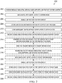
- FIGURES 1A-1B there is a diagram illustrating the signaling between a MTC device 102 (e.g., MS 102), a serving node 104 (e.g. SGSN 104) and a target serving node 106 (e.g. target SGSN 106) to implement the USR feature in accordance with an embodiment of the present disclosure.
- a MTC device 102 e.g., MS 102
- a serving node 104 e.g. SGSN 104
- target serving node 106 e.g. target SGSN 106
- the three main components namely the MTC device 102 (e.g., MS 102), the serving node 104 (e.g. SGSN 104), and the target serving node 106 (e.g. target SGSN 106) are shown interacting with one another when implementing the new USR feature as follows:
- the MTC device 102 receives the message 108 from the SGSN 104 when activating a PDP context with the SGSN 104, where the message 108 comprises an indication 109 which indicates that the SGSN 104 supports the USR feature (step 1 of FIGS. 1A-1B ).
- the message 108 is a PDP context related NAS message 108 which comprises a packet flow identifier information element which contains the indication which indicates that the SGSN 104 supports the USR feature (see FIGS. 6-7 ).
- the MTC device 102 sends the SN-PDU 110 having a payload which includes UDP/IP layers to the SGSN 104, where the SN-PDU 110 is associated with the PDP context with the SGSN 104 (step 2 of FIGS. 1A-1B ).
- the MTC device 102 enables the USR feature for the PDP context with the SGSN 104 (step 3 of FIGS. 1A-1B ).
- the MTC device 102 stores status information indicating the USR feature is enabled for the PDP context with the SGSN 104 (step 3 of FIGS. 1A-1B ).
- the MTC device 102 sends a subsequent SN-PDU 112 1 having a payload which excludes UDP/IP layers to the SGSN 104, where the subsequent SN-PDU 112 1 is associated with the PDP context with the SGSN 104 (step 5 of FIGS. 1A-1B -note: the MTC device 102 can send multiple subsequent SN-PDUs 112 2 , 112 3 ...112 x ).
- the MTC device 102 may receive the disable indicator 114 from the SGSN 104, where the disable indicator 114 comprises an indication which indicates that the USR feature is disabled for the PDP context with the SGSN 104 (step 9 of FIGS. 1A-1B ).
- the MTC device 102 may perform a cell re-selection based cell change to a new cell in a new Routing Area supported by the target serving node 106 (e.g., target SGSN 106) in which case it would perform a RAU procedure and implement the USR feature per steps 214, 216, 218, 220, 222, 224, 226 and 228 described next.
- the MTC device 102 upon deciding to perform a RAU procedure with the target SGSN 106 due to entering a new Routing Area would consider the USR feature to be disabled for the PDP context with the target SGSN 106 (step 10 of FIGS. 1A-1B ).
- the MTC device 102 sends the RAU request message 116 to the target SGSN 106 (step 11 of FIGS. 1A-1B ).
- the MTC device 102 receives the RAU accept message 118 from the target SGSN 106, where the RAU accept message 118 comprises an indication which indicates that the target SGSN 106 supports the USR feature (step 12 of FIGS. 1A-1B ).
- the MTC device 102 sends the SN-PDU 120 having a payload which includes UDP/IP layers to the target SGSN 106, where the SN-PDU 120 is associated with the PDP context with the target SGSN 106 (step 13 of FIGS. 1A-1B ).
- the MTC device 102 enables the USR feature for the PDP context with the target SGSN 106 (step 14 of FIGS. 1A-1B ).
- the MTC device 102 stores status information indicating the USR feature is enabled for the PDP context with the target SGSN 106 (step 14 of FIGS. 1A-1B ).
- the MTC device 102 sends a subsequent SN-PDU 122 1 having a payload which excludes UDP/IP layers to the target SGSN 106, where the subsequent SN-PDU 122 1 is associated with the PDP context with the target SGSN 106 (step 16 of FIGS.
- the MTC device 102 can send multiple subsequent SN-PDUs 122 2 , 122 3 ...122 x ).
- the MTC device 102 may receive the disable indicator 124 from the target SGSN 106, where the disable indicator 124 comprises an indication which indicates that the USR feature is disabled for the PDP context with the target SGSN 106 (step 20 of FIGS. 1A-1B ).
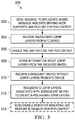
- the SGSN 104 sends the message 108 to the MTC device 102 when activating a PDP context with the MTC device 102, where the message 108 comprises an indication 109 which indicates that the SGSN 104 supports the USR feature (step 1 of FIGS. 1A-1B ).
- the message 108 is a PDP context related NAS message 108 which comprises a packet flow identifier information element which contains the indication which indicates that the SGSN 104 supports the USR feature (see FIGS. 6-7 ).
- the SGSN 104 receives the SN-PDU 110 having a payload which includes UDP/IP layers from the MTC device 102, where the SN-PDU 110 is associated with the PDP context with the MTC device 102 (step 3 of FIGS. 1A-1B ).
- the SGSN 104 upon receipt of the SN-PDU 110 enables the USR feature for the PDP context with the MTC device 102.
- the SGSN 104 stores information about the UDP/IP layers within the received SN-PDU 110. In one example, the SGSN 104 stores the information about the UDP/IP layers from the received SN-PDU 110 for as long as the PDP context with the MTC device 102 is retained.
- the SGSN 104 receives the subsequent SN-PDU 112 1 having a payload which excludes UDP/IP layers from the MTC device 102, where the subsequent SN-PDU 112 1 is associated with the PDP context with the MTC device 102 (step 5 of FIGS. 1A-1B ).
- the SGSN 104 upon receipt of the subsequent SN-PDU 112 1 re-generates UDP/IP layers associated with the subsequent SN-PDU 112 1 using the stored information from step 308 to create a N-PDU comprising the re-generated UDP/IP layers and the payload from the subsequent SN-PDU 112 1 (step 8 of FIGS. 1A-1B --note the SGSN 104 can receive multiple subsequent SN-PDUs 112 2 , 112 3 ...112 x and create multiple N-PDUs).
- the SGSN 104 may send the disable indicator 114 to the MTC device 102, where the disable indicator 114 comprises an indication which indicates that the USR feature is disabled for the PDP context with the SGSN 104 (step 9 of FIGS. 1A-1B ).
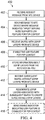
- the target serving node 106 e.g. target SGSN 106 for implementing the USR feature in accordance with an embodiment of the present disclosure.
- the target SGSN 106 receives the RAU request message 116 from the MTC device 102 (step 11 of FIGS. 1A-1B ).
- the target SGSN 106 sends the RAU accept message 118 to the MTC device 102, where the RAU accept message 118 comprises an indication 109 which indicates that the target SGSN 106 supports the USR feature (step 12 of FIGS. 1A-1B ).
- the target SGSN 106 receives the SN-PDU 120 having a payload which includes UDP/IP layers from the MTC device 102, where the SN-PDU 120 is associated with the PDP context with the MTC device 102 (step 14 of FIGS. 1A-1B ).
- the target SGSN 106 upon receipt of the SN-PDU 120 enables the USR feature for the PDP context with the MTC device 102.
- the target SGSN 106 stores information about the UDP/IP layers within the received SN-PDU 120.
- the target SGSN 106 stores the information about the UDP/IP layers from the received SN-PDU 120 for as long as the PDP context with the MTC device 102 is retained.
- the target SGSN 106 receives the subsequent SN-PDU 122 1 having a payload which excludes UDP/IP layers from the MTC device 102, where the subsequent SN-PDU 122 1 is associated with the PDP context with the MTC device 102 (step 16 of FIGS. 1A-1B ).
- the target SGSN 106 upon receipt of the subsequent SN-PDU 122 1 re-generates UDP/IP layers associated with the subsequent SN-PDU 122 1 using the stored information from step 410 to create a N-PDU comprising the re-generated UDP/IP layers and the payload from the subsequent SN-PDU 122 1 (step 17 of FIGS. 1A-1B --note the target SGSN 106 can receive multiple subsequent SN-PDUs 122 2 , 122 3 ...122 x and create multiple N-PDUs).
- the target SGSN 106 may send the disable indicator 124 to the MTC device 102, where the disable indicator 124 comprises an indication which indicates that the USR feature is disabled for the PDP context with the target SGSN 106 (step 19 of FIGS. 1A-1B ).
- the MTC device 102 comprises a memory 502, a processor 504 for executing instructions stored in the memory 502 and an input/output device 506 for communication with other nodes and devices such as the SGSN 104 and target SGSN 106 connected to a packet transport network 508.
- the serving node 104 e.g.
- the SGSN 1014 comprises a memory 510, a processor 512 suitable for executing instructions stored in the memory 510 as well as an input/output device 514 which is also connected to the packet transport network 508.
- the target serving node 106 (e.g. target SGSN 106) comprises a memory 516, a processor 518 suitable for executing instructions stored in the memory 516 as well as an input/output device 520 which is also connected to the packet transport network 508.
- the present arrangement of the MTC device 102 (e.g., MS 102), the serving node 104 (e.g. SGSN 104) and the target serving node 106 (e.g. target SGSN 106) are suitable for executing the various methods 200, 300 and 400 described herein with respect to FIGURES 1-4 .
- the MTC device 102 e.g., MS 102
- the serving node 104 e.g. SGSN 104
- the target serving node 106 e.g. target SGSN 106
- a typical network would comprise multiple MTC devices 102 and multiple serving nodes 104 and 106 (e.g. SGSN 104 and 106) as well as a plethora of other network nodes which may or may not be in the path of packets sent between the MTC device 102 and the serving nodes 104 and 106 (e.g. SGSN 104 and 106).
- a Radio Base Station is in radio connection with the MTC device 102, receiving packets from the MTC device 102 and forwarding them possibly through other network node(s) to one of the serving nodes 104 and 106 (e.g. SGSNs 104 and 106).
- the serving nodes 104 and 106 e.g. SGSNs 104 and 106.
- memories 502, 510 and 516 available, such as solid states drives, hard drives, RAM, ROM, EPROM, EEPROM etc. which could be used in implementing embodiments disclosed herein.
- the memory 502 used for the MTC device 102 would typically be different from the memories 510 and 516 used for the serving nodes 104 and 106 (e.g. SGSNs 104 and 106), however there is absolutely nothing preventing them for utilizing the same kind of memory.
- the processors 504, 512 and 518 indicated in the schematic view can be implemented in many different forms, such as an off-the-shelf microcontroller, an ASIC, FPGA etc.
- the PDP Context activation procedure can be used to inform the MTC device 102 when the SGSN 104 supports the USR feature for a given PDP Context.
- the MTC device 102 that supports USR will then realize that after sending an uplink SN-PDU 110 to such a SGSN 104 wherein the UDP/IP layers were included in the SN-PDU 110's PDU payload, that it can exclude the UDP/IP layers in all subsequent SN-PDUs 112 1 , 112 2 ...112 x sent to that SGSN 104 for that PDP Context.
- the SGSN 104 indicates it supports USR on a PDP Context basis by including the Packet Flow Identifier IE 109 within the PDP Context related NAS message 108 which can be modified to be as shown in FIGS. 6-7 .
- the MTC device 102 For the case where the USR feature is enabled for a given PDP Context, the MTC device 102 includes the UDP/IP layers present within at least the first uplink SN-PDU 110 sent to the SGSN 104 after PDP Context activation/modification. Thereafter, the MTC device 102 can omit the UDP/IP layers when sending subsequent SN-PDUs 112 1 , 112 2 ...112 x corresponding to that PDP Context to the SGSN 104.
- 3GPP TS 24.008 V12.4.0 specifies the procedures used at the radio interface core network within the 3rd generation mobile telecommunications system and the digital cellular telecommunications system.
- the following additions to the 3GPP TS 24.008 are necessary to implement at least some embodiments disclosed herein. It should also be noted that while the present embodiments are described in the context of GSM it may also be applied in the context of other radio interfaces, for example LTE and UMTS.
- UDP is a minimal message-oriented Transport Layer protocol that is documented in IETF RFC 768.
- UDP provides no guarantees to the upper layer protocol for message delivery and the UDP protocol layer retains no state of UDP messages once sent. For this reason, UDP is sometimes referred to as "Unreliable Datagram Protocol".
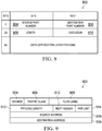
- UDP provides application multiplexing (via port numbers) and integrity verification (via checksum) of the header and payload (see FIGURE 8 ). If transmission reliability is desired, it must be implemented in the user's application or at a lower layer in the protocol stack.
- the UDP header 802 consists of four fields 804, 806, 808 and 810 each of which is 2 bytes (16 bits).
- Source Port Number field 804 This field 804 identifies the sender's port when meaningful and should be assumed to be the port to reply to if needed. If it is not used, then it should be zero. If the source host is the client, then the port number is likely to be an ephemeral port number. If the source host is the server, then the port number is likely to be a well-known port number. This field 804 is expected to be static based on the assumptions provided above and is optional for IPv6.
- Destination Port Number field 806 This field 806 identifies the receiver's port and is required. Similar to source port number, if the client is the destination host then the port number will likely be an ephemeral port number and if the destination host is the server then the port number will likely be a well-known port number. This field 806 is expected to be static based on the assumptions provided above.
- Length field 808 This field 808 specifies the length in bytes of the entire UDP datagram: header and data. The minimum length is 8 bytes since that is the length of the header. The field size sets a theoretical limit of 65,535 bytes (8 byte header + 65,527 bytes of data) for a UDP datagram. The practical limit for the data length which is imposed by the underlying IPv4 protocol is 65,507 bytes (65,535 - 8 byte UDP header - 20 byte IP header). This field 808 will vary as the length of the application payload varies.
- Checksum field 810 This field 810 is used for error-checking of the header and data. If no checksum is generated by the transmitter, then the field uses the value all-zeros. This field 810 is not optional for IPv6. The field 810 could either be made static (i.e., set to all-zeros) or set according header and data content. The field 810 can be set to all-zeros for the case of GSM since the LLC PDUs sent from a UE (e.g., MS, MTC device) to the SGSN already support a checksum field (i.e. the integrity of the application layer payload sent by the MS will be ensured using legacy LLC operation via CRC-24).
- a UE e.g., MS, MTC device
- IPv6 data packet comprises of two main parts, the header and the payload.
- the IPv6 header 902 contains the following fields: Version field 904: This 4-bit field 904 contains the number "6". It indicates the version of the IPv6 protocol. This field 904 is the same size as the IPv4 version field that contains the number "4". However, this field 904 has a limited use because IPv4 and IPv6 packets are not distinguished based on the value in the version field but by the protocol type present in the layer 2 envelope. This field 904 will be static for very long periods of time.
- Traffic Class field 906 This 8-bit field 906 can assume different values to enable the source node to differentiate between the packets generated by it by associating different delivery priorities to them. This field 906 is subsequently used by the originating node and the routers to identify the data packets that belong to the same traffic class and distinguish between packets with different priorities. This field 906 is expected to be static based on the assumptions provided above.
- Flow Label field 908 This 20-bit field 908 can be used by a source to label a set of packets belonging to the same flow.
- This field 908 is expected to be set to "0" based on the assumptions provided above.
- This 16-bit field 910 contains the length of the data field in octets/bits following the IPv6 packet header (i.e. this will reflect the UDP header length + the application layer payload length).
- the 16-bit Payload length field 910 puts an upper limit on the maximum packet payload to 64 kilobytes. In case a higher packet payload is required, a jumbo payload extension header is provided in the IPv6 protocol.
- a jumbo payload (jumbogram) is indicated by the value zero in the Payload Length field 910. Jumbograms are frequently used in supercomputer communications using the IPv6 protocol to transmit heavy data payload. This field 910 will vary as the length of the application payload varies.
- Next Header field 912 This 8-bit field 912 identifies the type of header immediately following the IPv6 header and located at the beginning of the data field (payload) of the IPv6 packet.
- This field 912 usually specifies the transport layer protocol used by a packet's payload.
- the two most common kinds of Next Headers are TCP and UDP, but many other headers are also possible.
- the format adopted for this field 912 is the one proposed for IPv4 by RFC 1700.
- the Next Header field 912 is similar to the IPv4 Protocol field. This field 912 is expected to be static (i.e., set to indicate UDP) based on the assumptions provided above.
- Hop Limit field 914 This 8-bit field 914 is decremented by one, by each node (typically a router) that forwards a packet. If the Hop Limit field 914 is decremented to zero, the packet is discarded, The main function of this field 914 is to identify and to discard packets that are stuck in an indefinite loop due to any routing information errors, The 8-bit field 914 also puts an upper limit on the maximum number of links between two IPv6 nodes. In this way, an IPv6 data packet is allowed a maximum of 255 hops before it is eventually discarded. An IPv6 data packet can pass through a maximum of 254 routers before being discarded. This field 914 is expected to be static based on the assumptions provided above.
- Source Address field 916 and Destination Address field 918 are each 16-octets.
- the present disclosure describes an example where the SGSN 104 indicates USR support for a PDP context in a NAS message 108 sent to the MTC device 102.
- the MTC device 102 stores the information and sends a first SN-PDP message 110 including UDP/P layers.
- the SGSN 104 enables USR for the PDP-context and stores necessary information for the PDP-context.
- the SGSN 104 Upon receiving such SN-PDP messages 112 1 , 112 2 ...112 x , the SGSN 104 re-generates the UDP/IP layers for the PDP-context using the stored information.
- the optimization associated with the USR feature where the MTC device 102 eliminates the repeated inclusion of UDP/IP protocol overhead (46 or 48 octets) for such MTC data packets sent over the radio interface is beneficial due to the fact that MTC devices 102 are expected to commonly transmit small MTC data packets (e.g.
- the radio interface bandwidth savings that can be realized using embodiments of the USR feature disclosed herein is expected to significantly improve the PS domain traffic capacity (PDCH utilization) of any wireless network supporting the MTC use case as well as contribute to MTC device power savings in that few radio blocks will need to be transmitted.
- PDCH utilization PS domain traffic capacity
Landscapes
- Engineering & Computer Science (AREA)
- Computer Networks & Wireless Communication (AREA)
- Signal Processing (AREA)
- Mobile Radio Communication Systems (AREA)
Claims (24)
- Dispositif de communication de type machine, MTC, (102) configuré pour mettre en oeuvre une caractéristique de réduction de pile de liaison montante, USR, avec un noeud de desserte (104), le dispositif MTC comprenant :un processeur (504) ; etau moins une mémoire (502) qui mémorise des instructions exécutables par processeur, dans lequel le processeur est en interface avec l'au moins une mémoire pour exécuter les instructions exécutables par processeur, de telle manière que ledit dispositif MTC soit utilisable pour effectuer :la réception (202) d'un message (108, 118) en provenance du noeud de desserte lors de l'activation d'un contexte de protocole de données en paquets, PDP, avec le noeud de desserte, dans lequel le message comprend une indication (109) qui indique que le noeud de desserte prend en charge la caractéristique USR ;l'envoi (204), au noeud de desserte, d'une unité de données de protocole de sous-réseau, SN-PDU, (110) ayant une charge utile comprenant des couches de protocole de datagrammes d'utilisateur/protocole Internet, UDP/IP, dans lequel la SN-PDU est associée au contexte PDP avec le noeud de desserte ;l'activation (206) de la caractéristique USR pour le contexte PDP avec le noeud de desserte ;la mémorisation (208) d'informations de statut indiquant que la caractéristique USR est activée pour le contexte PDP avec le noeud de desserte ; etl'envoi (210), au noeud de desserte, d'une SN-PDU suivante (1121) ayant une charge utile excluant des couches UDP/IP, dans lequel la SN-PDU suivante est associée au contexte PDP avec le noeud de desserte, dans lequel la SN-PDU suivante comprend en outre un en-tête avec un champ qui indique que les couches UDP/IP ont été exclues de celui-ci.
- Dispositif MTC selon la revendication 1, dans lequel le dispositif MTC est en outre utilisable pour effectuer :
la réception (212) d'une indication de désactivation (114, 124) en provenance du noeud de desserte, dans lequel l'indication de désactivation comprend une indication qui indique que la caractéristique USR est désactivée pour le contexte PDP avec le noeud de desserte. - Dispositif MTC selon la revendication 1, dans lequel le champ est un champ d'identifiant de point d'accès de desserte de réseau, NSAPI, réglé à une valeur spécifique qui indique que les couches UDP/IP ont été exclues de celui-ci.
- Dispositif MTC selon la revendication 1, dans lequel le message (108, 118) est l'un de :un message de couche sans accès, NAS, lié au contexte PDP (108) comprenant un élément d'information d'identifiant de flux de paquets qui contient l'indication indiquant que le noeud de desserte prend en charge la caractéristique USR ; ouun message d'acceptation de mise à jour de zone d'acheminement, RAU, (118).
- Dispositif MTC selon la revendication 1, dans lequel le dispositif MTC est en outre utilisable pour mettre en oeuvre la caractéristique USR avec un noeud de desserte cible (106) lors du changement d'une cellule du noeud de desserte à une nouvelle cellule du noeud de desserte cible, comme suit :lors de la décision d'effectuer une procédure de mise à jour de zone d'acheminement, RAU, avec le noeud de desserte cible parce que la nouvelle cellule du noeud de desserte cible appartient à une zone d'acheminement qui est différente de celle de la cellule du noeud de desserte, la prise en compte (214) de la caractéristique USR à désactiver pour un contexte PDP avec le noeud de desserte cible ;l'envoi (216) d'un message de demande RAU (116) au noeud de desserte cible ;la réception (218) d'un message d'acceptation RAU (118) en provenance du noeud de desserte cible, dans lequel le message d'acceptation RAU comprend une indication indiquant que le noeud de desserte cible prend en charge la caractéristique USR ;l'envoi (220), au noeud de desserte cible, d'une SN-PDU (120) ayant une charge utile comprenant des couches UDP/IP, dans lequel la SN-PDU est associée au contexte PDP avec le noeud de desserte cible ;l'activation (222) de la caractéristique USR pour le contexte PDP avec le noeud de desserte cible ;la mémorisation (224) d'informations de statut indiquant que la caractéristique USR est activée pour le contexte PDP avec le noeud de desserte cible ; etl'envoi (226), au noeud de desserte cible, d'une SN-PDU suivante (1221) ayant une charge utile qui exclut des couches UDP/IP, dans lequel la SN-PDU suivante est associée au contexte PDP avec le noeud de desserte cible.
- Dispositif MTC selon la revendication 1, dans lequel le dispositif MTC est une station mobile et le noeud de desserte est un noeud de prise en charge de GPRS de desserte, SGSN.
- Procédé (200) dans un dispositif de communication de type machine, MTC, (102) pour mettre en oeuvre une caractéristique de réduction de pile de liaison montante, USR, avec un noeud de desserte (104), le procédé comprenant :la réception (202) d'un message (108, 118) en provenance du noeud de desserte lors de l'activation d'un contexte de protocole de données en paquets, PDP, avec le noeud de desserte, dans lequel le message comprend une indication (109) qui indique que le noeud de desserte prend en charge la caractéristique USR ;l'envoi (204), au noeud de desserte, d'une unité de données de protocole de sous-réseau, SN-PDU, (110) ayant une charge utile comprenant des couches de protocole de datagrammes d'utilisateur/protocole Internet, UDP/IP, dans lequel la SN-PDU est associée au contexte PDP avec le noeud de desserte ;l'activation (206) de la caractéristique USR pour le contexte PDP avec le noeud de desserte ;la mémorisation (208) d'informations de statut indiquant que la caractéristique USR est activée pour le contexte PDP avec le noeud de desserte ; etl'envoi (210), au noeud de desserte, d'une SN-PDU suivante (1121) ayant une charge utile excluant des couches UDP/IP, dans lequel la SN-PDU suivante est associée au contexte PDP avec le noeud de desserte, dans lequel la SN-PDU suivante comprend en outre un en-tête avec un champ qui indique que les couches UDP/IP ont été exclues de celui-ci.
- Procédé selon la revendication 7, comprenant en outre :
la réception (212) d'une indication de désactivation (114, 124) en provenance du noeud de desserte, dans lequel l'indication de désactivation comprend une indication qui indique que la caractéristique USR est désactivée pour le contexte PDP avec le noeud de desserte. - Procédé selon la revendication 7, dans lequel le champ est un champ d'identifiant de point d'accès de desserte de réseau, NSAPI, réglé à une valeur spécifique qui indique que les couches UDP/IP ont été exclues de celui-ci.
- Procédé selon la revendication 7, dans lequel le message (108, 118) est l'un de :un message de couche sans accès, NAS, lié au contexte PDP (108) comprenant un élément d'information d'identifiant de flux de paquets qui contient l'indication indiquant que le noeud de desserte prend en charge la caractéristique USR ; ouun message d'acceptation de mise à jour de zone d'acheminement, RAU, (118).
- Procédé selon la revendication 7, comprenant en outre :lors de la décision d'effectuer une procédure de mise à jour de zone d'acheminement, RAU, avec un noeud de desserte cible (106) après le changement d'une cellule du noeud de desserte à une nouvelle cellule du noeud de desserte cible, dans lequel la nouvelle cellule du noeud de desserte cible appartient à une zone d'acheminement qui est différente de celle de la cellule du noeud de desserte, la prise en compte (214) de la caractéristique USR à désactiver pour un contexte PDP avec le noeud de desserte cible ;l'envoi (216) d'un message de demande RAU (116) au noeud de desserte cible ;la réception (218) d'un message d'acceptation RAU (118) en provenance du noeud de desserte cible, dans lequel le message d'acceptation RAU comprend une indication indiquant que le noeud de desserte cible prend en charge la caractéristique USR ;l'envoi (220), au noeud de desserte cible, d'une SN-PDU (120) ayant une charge utile comprenant des couches UDP/IP, dans lequel la SN-PDU est associée au contexte PDP avec le noeud de desserte cible ;l'activation (222) de la caractéristique USR pour le contexte PDP avec le noeud de desserte cible ;la mémorisation (224) d'informations de statut indiquant que la caractéristique USR est activée pour le contexte PDP avec le noeud de desserte cible ; etl'envoi (226), au noeud de desserte cible, d'une SN-PDU suivante (1221) ayant une charge utile qui exclut des couches UDP/IP, dans lequel la SN-PDU suivante est associée au contexte PDP avec le noeud de desserte cible.
- Procédé selon la revendication 7, dans lequel le dispositif MTC est une station mobile et le noeud de desserte est un noeud de prise en charge de GPRS de desserte, SGSN.
- Noeud de desserte (104, 106) configuré pour mettre en oeuvre une caractéristique de réduction de pile de liaison montante, USR, avec un dispositif de communication de type machine, MTC, (102), le noeud de desserte comprenant :un processeur (512, 518) ; etau moins une mémoire (510, 516) qui mémorise des instructions exécutables par processeur, dans lequel le processeur est en interface avec l'au moins une mémoire pour exécuter les instructions exécutables par processeur, de telle manière que ledit noeud de desserte soit utilisable pour effectuer :l'envoi (302, 404) d'un message (108, 116) au dispositif MTC lors de l'activation d'un contexte de protocole de données en paquets, PDP, avec le dispositif MTC, dans lequel le message comprend une indication (109) qui indique que le noeud de desserte prend en charge la caractéristique USR ;la réception (304, 406), en provenance du dispositif MTC, d'une unité de données de protocole de sous-réseau, SN-PDU, (110, 120) ayant une charge utile comprenant des couches de protocole de datagrammes d'utilisateur/protocole Internet, UDP/IP, dans lequel la SN-PDU est associée au contexte PDP avec le dispositif MTC ;lors de la réception de la SN-PDU, l'activation (306, 408) de la caractéristique USR pour le contexte PDP avec le dispositif MTC et la mémorisation (308, 410) d'informations relatives aux couches UDP/IP à l'intérieur de la SN-PDU reçue ;la réception (310, 412), en provenance du dispositif MTC, d'une SN-PDU suivante (1121, 1221) ayant une charge utile excluant des couches UDP/IP, dans lequel la SN-PDU suivante est associée au contexte PDP avec le dispositif MTC, dans lequel la SN-PDU suivante comprend en outre un en-tête avec un champ qui indique que les couches UDP/IP ont été exclues de celui-ci ; etlors de la réception de la SN-PDU suivante, la régénération (312, 414) des couches UDP/IP associées à la SN-PDU en utilisant les informations mémorisées pour créer une unité de données de protocole de réseau, N-PDU, comprenant les couches UDP/IP régénérées et la charge utile de la SN-PDU suivante.
- Noeud de desserte selon la revendication 13, dans lequel le noeud de desserte est en outre utilisable pour effectuer :
l'envoi (314, 416) d'un indicateur de désactivation (114, 124) au dispositif MTC, dans lequel l'indicateur de désactivation comprend une indication qui indique que la caractéristique USR est désactivée pour le contexte PDP avec le dispositif MTC. - Noeud de desserte selon la revendication 13, dans lequel l'opération de mémorisation comprend en outre :
la mémorisation d'informations relatives aux couches UDP/IP provenant de la SN-PDU reçue pendant la durée de conservation du contexte PDP avec le dispositif MTC. - Noeud de desserte selon la revendication 13, dans lequel le champ est un champ d'identifiant de point d'accès de desserte de réseau, NSAPI, réglé à une valeur spécifique qui indique que les couches UDP/IP ont été exclues de celui-ci.
- Noeud de desserte selon la revendication 13, dans lequel le message (108, 116) est l'un de :un message de couche sans accès, NAS, lié au contexte PDP (108) comprenant un élément d'information d'identifiant de flux de paquets qui contient l'indication indiquant que le noeud de desserte prend en charge la caractéristique USR ; ouun message d'acceptation de mise à jour de zone d'acheminement, RAU, (116).
- Noeud de desserte selon la revendication 13, dans lequel le dispositif MTC est une station mobile et le noeud de desserte est un noeud de prise en charge de GPRS de desserte, SGSN.
- Procédé (300, 400) dans un noeud de desserte (104, 106) pour mettre en oeuvre une caractéristique de réduction de pile de liaison montante, USR, avec un dispositif de communication de type machine, MTC, (102), le procédé comprenant :l'envoi (302, 404) d'un message (108, 116) au dispositif MTC lors de l'activation d'un contexte de protocole de données en paquets, PDP, avec le dispositif MTC, dans lequel le message comprend une indication (109) qui indique que le noeud de desserte prend en charge la caractéristique USR ;la réception (304, 406), en provenance du dispositif MTC, d'une unité de données de protocole de sous-réseau, SN-PDU, (110, 120) ayant une charge utile comprenant des couches de protocole de datagrammes d'utilisateur/protocole Internet, UDP/IP, dans lequel la SN-PDU est associée au contexte PDP avec le dispositif MTC ;lors de la réception de la SN-PDU, l'activation (306, 408) de la caractéristique USR pour le contexte PDP avec le dispositif MTC et la mémorisation (308, 410) d'informations relatives aux couches UDP/IP à l'intérieur de la SN-PDU reçue ;la réception (310, 412), en provenance du dispositif MTC, d'une SN-PDU suivante (1121, 1221) ayant une charge utile excluant des couches UDP/IP, dans lequel la SN-PDU suivante est associée au contexte PDP avec le dispositif MTC, dans lequel la SN-PDU suivante comprend en outre un en-tête avec un champ qui indique que les couches UDP/IP ont été exclues de celui-ci ; etlors de la réception de la SN-PDU suivante, la régénération (312, 414) des couches UDP/IP associées à la SN-PDU en utilisant les informations mémorisées pour créer une unité de données de protocole de réseau, N-PDU, comprenant les couches UDP/IP régénérées et la charge utile de la SN-PDU suivante.
- Procédé selon la revendication 19, comprenant en outre :
l'envoi (314, 416) d'un indicateur de désactivation (114, 124) au dispositif MTC, dans lequel l'indicateur de désactivation comprend une indication qui indique que la caractéristique USR est désactivée pour le contexte PDP avec le dispositif MTC. - Procédé selon la revendication 19, dans lequel l'opération de mémorisation comprend en outre :
la mémorisation d'informations relatives aux couches UDP/IP provenant de la SN-PDU reçue pendant la durée de conservation du contexte PDP avec le dispositif MTC. - Procédé selon la revendication 19, dans lequel le champ est un champ d'identifiant de point d'accès de desserte de réseau, NSAPI, réglé à une valeur spécifique qui indique que les couches UDP/IP ont été exclues de celui-ci.
- Procédé selon la revendication 19, dans lequel le message (108, 116) est l'un de :un message de couche sans accès, NAS, lié au contexte PDP (108) comprenant un élément d'information d'identifiant de flux de paquets qui contient l'indication indiquant que le noeud de desserte prend en charge la caractéristique USR ; ouun message d'acceptation de mise à jour de zone d'acheminement, RAU, (116).
- Procédé selon la revendication 19, dans lequel le dispositif MTC est une station mobile et le noeud de desserte est un noeud de prise en charge de GPRS de desserte, SGSN.
Applications Claiming Priority (3)
| Application Number | Priority Date | Filing Date | Title |
|---|---|---|---|
| US201461937283P | 2014-02-07 | 2014-02-07 | |
| US14/611,894 US20150230122A1 (en) | 2014-02-07 | 2015-02-02 | Mtc device, serving node, and various methods for implementing an uplink stack reduction feature |
| PCT/IB2015/050815 WO2015118445A1 (fr) | 2014-02-07 | 2015-02-03 | Dispositif de communication du type machine (mtc), nœud de desserte et différents procédés pour mettre en œuvre une fonction de réduction de pile de liaison montante |
Publications (2)
| Publication Number | Publication Date |
|---|---|
| EP3103279A1 EP3103279A1 (fr) | 2016-12-14 |
| EP3103279B1 true EP3103279B1 (fr) | 2018-05-02 |
Family
ID=53776150
Family Applications (1)
| Application Number | Title | Priority Date | Filing Date |
|---|---|---|---|
| EP15709358.4A Active EP3103279B1 (fr) | 2014-02-07 | 2015-02-03 | Dispositif de communication du type machine (mtc), noeud de desserte et différents procédés pour mettre en oeuvre une fonction de réduction de pile de liaison montante |
Country Status (4)
| Country | Link |
|---|---|
| US (1) | US20150230122A1 (fr) |
| EP (1) | EP3103279B1 (fr) |
| BR (1) | BR112016017994A2 (fr) |
| WO (1) | WO2015118445A1 (fr) |
Families Citing this family (1)
| Publication number | Priority date | Publication date | Assignee | Title |
|---|---|---|---|---|
| WO2017047423A1 (fr) * | 2015-09-17 | 2017-03-23 | ソニー株式会社 | Dispositif d'émission, dispositif de réception et procédé de traitement de données |
Family Cites Families (6)
| Publication number | Priority date | Publication date | Assignee | Title |
|---|---|---|---|---|
| GB0600601D0 (en) * | 2006-01-12 | 2006-02-22 | Vodafone Plc | Telecommunications networks and devices |
| JP4882959B2 (ja) * | 2007-10-26 | 2012-02-22 | 富士通株式会社 | パケット通信方法並びにパケット通信システム、管理装置、無線端末及びパケット通信装置 |
| US9769287B2 (en) * | 2010-05-10 | 2017-09-19 | Telefonaktiebolaget Lm Ericsson (Publ) | Reducing protocol overhead in single-block packet access procedures |
| US20120182934A1 (en) * | 2011-01-18 | 2012-07-19 | John Diachina | Application layer communication via an intermediate node |
| CN102843679A (zh) * | 2011-06-24 | 2012-12-26 | 中怡(苏州)科技有限公司 | 无线数据流的传输方法与系统 |
| WO2014133589A1 (fr) * | 2013-03-01 | 2014-09-04 | Intel Corporation | Décharge de trafic de réseau local sans-fil (wlan) |
-
2015
- 2015-02-02 US US14/611,894 patent/US20150230122A1/en not_active Abandoned
- 2015-02-03 BR BR112016017994A patent/BR112016017994A2/pt not_active IP Right Cessation
- 2015-02-03 EP EP15709358.4A patent/EP3103279B1/fr active Active
- 2015-02-03 WO PCT/IB2015/050815 patent/WO2015118445A1/fr active Application Filing
Non-Patent Citations (1)
| Title |
|---|
| None * |
Also Published As
| Publication number | Publication date |
|---|---|
| WO2015118445A1 (fr) | 2015-08-13 |
| BR112016017994A2 (pt) | 2017-08-08 |
| EP3103279A1 (fr) | 2016-12-14 |
| US20150230122A1 (en) | 2015-08-13 |
Similar Documents
| Publication | Publication Date | Title |
|---|---|---|
| US11032740B2 (en) | Method for performing a re-establishment of a PDCP entity associated with UM RLC entity in wireless communication system and a device therefor | |
| US10680967B2 (en) | Method for handling state variables of a PDCP entity in wireless communication system and a device therefor | |
| JP4906844B2 (ja) | 無線移動通信システムで下位階層データブロックを生成する方法 | |
| US8355331B2 (en) | Method for transmitting PDCP status report | |
| US7729334B2 (en) | Apparatus and method for transmitting data blocks based on priority | |
| TWI387285B (zh) | 在無線裝置與網路間傳輸資料單元之序列的無線通訊方法 | |
| US20160234851A1 (en) | Data transmission apparatus and method | |
| WO2021000827A1 (fr) | Procédé et appareil d'établissement de liaison de transmission de données, et support de stockage lisible par ordinateur | |
| KR20200004802A (ko) | 통신 디바이스, 인프라스트럭처 장비, 무선 통신 네트워크 및 방법들 | |
| JP2014525196A (ja) | シグナリング無線ベアラを介したショートパケットデータメッセージの送信 | |
| US20190230682A1 (en) | Data transmission method, apparatus, and system | |
| KR101473010B1 (ko) | 패킷망을 이용하여 서킷서비스를 제공하는 방법 | |
| US20170366374A1 (en) | Gateway apparatus and control method thereof | |
| US20120182934A1 (en) | Application layer communication via an intermediate node | |
| JP5965061B2 (ja) | データ伝送方法、ネットワーク要素デバイスおよび通信システム | |
| WO2019098148A1 (fr) | Dispositif terminal, dispositif station de base, et procédé | |
| JP2023176001A (ja) | 端末装置、通信方法、および基地局装置 | |
| EP3103279B1 (fr) | Dispositif de communication du type machine (mtc), noeud de desserte et différents procédés pour mettre en oeuvre une fonction de réduction de pile de liaison montante | |
| US20150230121A1 (en) | Mtc device, serving node, and various methods for implementing a downlink stack reduction feature | |
| WO2020031664A1 (fr) | Dispositif terminal, dispositif de station de base, procédé et circuit intégré | |
| EP4109962B1 (fr) | Procédé de transmission de rapport d'état pdcp |
Legal Events
| Date | Code | Title | Description |
|---|---|---|---|
| PUAI | Public reference made under article 153(3) epc to a published international application that has entered the european phase |
Free format text: ORIGINAL CODE: 0009012 |
|
| STAA | Information on the status of an ep patent application or granted ep patent |
Free format text: STATUS: REQUEST FOR EXAMINATION WAS MADE |
|
| 17P | Request for examination filed |
Effective date: 20160809 |
|
| AK | Designated contracting states |
Kind code of ref document: A1 Designated state(s): AL AT BE BG CH CY CZ DE DK EE ES FI FR GB GR HR HU IE IS IT LI LT LU LV MC MK MT NL NO PL PT RO RS SE SI SK SM TR |
|
| AX | Request for extension of the european patent |
Extension state: BA ME |
|
| DAX | Request for extension of the european patent (deleted) | ||
| RIC1 | Information provided on ipc code assigned before grant |
Ipc: H04W 28/02 20090101ALI20170713BHEP Ipc: H04W 28/06 20090101AFI20170713BHEP |
|
| GRAP | Despatch of communication of intention to grant a patent |
Free format text: ORIGINAL CODE: EPIDOSNIGR1 |
|
| STAA | Information on the status of an ep patent application or granted ep patent |
Free format text: STATUS: GRANT OF PATENT IS INTENDED |
|
| INTG | Intention to grant announced |
Effective date: 20170918 |
|
| GRAS | Grant fee paid |
Free format text: ORIGINAL CODE: EPIDOSNIGR3 |
|
| GRAA | (expected) grant |
Free format text: ORIGINAL CODE: 0009210 |
|
| STAA | Information on the status of an ep patent application or granted ep patent |
Free format text: STATUS: THE PATENT HAS BEEN GRANTED |
|
| AK | Designated contracting states |
Kind code of ref document: B1 Designated state(s): AL AT BE BG CH CY CZ DE DK EE ES FI FR GB GR HR HU IE IS IT LI LT LU LV MC MK MT NL NO PL PT RO RS SE SI SK SM TR |
|
| REG | Reference to a national code |
Ref country code: GB Ref legal event code: FG4D |
|
| REG | Reference to a national code |
Ref country code: CH Ref legal event code: EP Ref country code: AT Ref legal event code: REF Ref document number: 996537 Country of ref document: AT Kind code of ref document: T Effective date: 20180515 |
|
| REG | Reference to a national code |
Ref country code: DE Ref legal event code: R096 Ref document number: 602015010680 Country of ref document: DE Ref country code: IE Ref legal event code: FG4D |
|
| REG | Reference to a national code |
Ref country code: DE Ref legal event code: R096 Ref document number: 602015010680 Country of ref document: DE |
|
| REG | Reference to a national code |
Ref country code: NL Ref legal event code: MP Effective date: 20180502 |
|
| REG | Reference to a national code |
Ref country code: LT Ref legal event code: MG4D |
|
| PG25 | Lapsed in a contracting state [announced via postgrant information from national office to epo] |
Ref country code: ES Free format text: LAPSE BECAUSE OF FAILURE TO SUBMIT A TRANSLATION OF THE DESCRIPTION OR TO PAY THE FEE WITHIN THE PRESCRIBED TIME-LIMIT Effective date: 20180502 Ref country code: SE Free format text: LAPSE BECAUSE OF FAILURE TO SUBMIT A TRANSLATION OF THE DESCRIPTION OR TO PAY THE FEE WITHIN THE PRESCRIBED TIME-LIMIT Effective date: 20180502 Ref country code: NO Free format text: LAPSE BECAUSE OF FAILURE TO SUBMIT A TRANSLATION OF THE DESCRIPTION OR TO PAY THE FEE WITHIN THE PRESCRIBED TIME-LIMIT Effective date: 20180802 Ref country code: FI Free format text: LAPSE BECAUSE OF FAILURE TO SUBMIT A TRANSLATION OF THE DESCRIPTION OR TO PAY THE FEE WITHIN THE PRESCRIBED TIME-LIMIT Effective date: 20180502 Ref country code: LT Free format text: LAPSE BECAUSE OF FAILURE TO SUBMIT A TRANSLATION OF THE DESCRIPTION OR TO PAY THE FEE WITHIN THE PRESCRIBED TIME-LIMIT Effective date: 20180502 Ref country code: BG Free format text: LAPSE BECAUSE OF FAILURE TO SUBMIT A TRANSLATION OF THE DESCRIPTION OR TO PAY THE FEE WITHIN THE PRESCRIBED TIME-LIMIT Effective date: 20180802 |
|
| PG25 | Lapsed in a contracting state [announced via postgrant information from national office to epo] |
Ref country code: RS Free format text: LAPSE BECAUSE OF FAILURE TO SUBMIT A TRANSLATION OF THE DESCRIPTION OR TO PAY THE FEE WITHIN THE PRESCRIBED TIME-LIMIT Effective date: 20180502 Ref country code: NL Free format text: LAPSE BECAUSE OF FAILURE TO SUBMIT A TRANSLATION OF THE DESCRIPTION OR TO PAY THE FEE WITHIN THE PRESCRIBED TIME-LIMIT Effective date: 20180502 Ref country code: LV Free format text: LAPSE BECAUSE OF FAILURE TO SUBMIT A TRANSLATION OF THE DESCRIPTION OR TO PAY THE FEE WITHIN THE PRESCRIBED TIME-LIMIT Effective date: 20180502 Ref country code: HR Free format text: LAPSE BECAUSE OF FAILURE TO SUBMIT A TRANSLATION OF THE DESCRIPTION OR TO PAY THE FEE WITHIN THE PRESCRIBED TIME-LIMIT Effective date: 20180502 Ref country code: GR Free format text: LAPSE BECAUSE OF FAILURE TO SUBMIT A TRANSLATION OF THE DESCRIPTION OR TO PAY THE FEE WITHIN THE PRESCRIBED TIME-LIMIT Effective date: 20180803 |
|
| REG | Reference to a national code |
Ref country code: AT Ref legal event code: MK05 Ref document number: 996537 Country of ref document: AT Kind code of ref document: T Effective date: 20180502 |
|
| PG25 | Lapsed in a contracting state [announced via postgrant information from national office to epo] |
Ref country code: CZ Free format text: LAPSE BECAUSE OF FAILURE TO SUBMIT A TRANSLATION OF THE DESCRIPTION OR TO PAY THE FEE WITHIN THE PRESCRIBED TIME-LIMIT Effective date: 20180502 Ref country code: RO Free format text: LAPSE BECAUSE OF FAILURE TO SUBMIT A TRANSLATION OF THE DESCRIPTION OR TO PAY THE FEE WITHIN THE PRESCRIBED TIME-LIMIT Effective date: 20180502 Ref country code: SK Free format text: LAPSE BECAUSE OF FAILURE TO SUBMIT A TRANSLATION OF THE DESCRIPTION OR TO PAY THE FEE WITHIN THE PRESCRIBED TIME-LIMIT Effective date: 20180502 Ref country code: DK Free format text: LAPSE BECAUSE OF FAILURE TO SUBMIT A TRANSLATION OF THE DESCRIPTION OR TO PAY THE FEE WITHIN THE PRESCRIBED TIME-LIMIT Effective date: 20180502 Ref country code: AT Free format text: LAPSE BECAUSE OF FAILURE TO SUBMIT A TRANSLATION OF THE DESCRIPTION OR TO PAY THE FEE WITHIN THE PRESCRIBED TIME-LIMIT Effective date: 20180502 Ref country code: PL Free format text: LAPSE BECAUSE OF FAILURE TO SUBMIT A TRANSLATION OF THE DESCRIPTION OR TO PAY THE FEE WITHIN THE PRESCRIBED TIME-LIMIT Effective date: 20180502 Ref country code: EE Free format text: LAPSE BECAUSE OF FAILURE TO SUBMIT A TRANSLATION OF THE DESCRIPTION OR TO PAY THE FEE WITHIN THE PRESCRIBED TIME-LIMIT Effective date: 20180502 |
|
| REG | Reference to a national code |
Ref country code: DE Ref legal event code: R097 Ref document number: 602015010680 Country of ref document: DE |
|
| PG25 | Lapsed in a contracting state [announced via postgrant information from national office to epo] |
Ref country code: IT Free format text: LAPSE BECAUSE OF FAILURE TO SUBMIT A TRANSLATION OF THE DESCRIPTION OR TO PAY THE FEE WITHIN THE PRESCRIBED TIME-LIMIT Effective date: 20180502 Ref country code: SM Free format text: LAPSE BECAUSE OF FAILURE TO SUBMIT A TRANSLATION OF THE DESCRIPTION OR TO PAY THE FEE WITHIN THE PRESCRIBED TIME-LIMIT Effective date: 20180502 |
|
| PLBE | No opposition filed within time limit |
Free format text: ORIGINAL CODE: 0009261 |
|
| STAA | Information on the status of an ep patent application or granted ep patent |
Free format text: STATUS: NO OPPOSITION FILED WITHIN TIME LIMIT |
|
| 26N | No opposition filed |
Effective date: 20190205 |
|
| PG25 | Lapsed in a contracting state [announced via postgrant information from national office to epo] |
Ref country code: SI Free format text: LAPSE BECAUSE OF FAILURE TO SUBMIT A TRANSLATION OF THE DESCRIPTION OR TO PAY THE FEE WITHIN THE PRESCRIBED TIME-LIMIT Effective date: 20180502 |
|
| REG | Reference to a national code |
Ref country code: CH Ref legal event code: PL |
|
| PG25 | Lapsed in a contracting state [announced via postgrant information from national office to epo] |
Ref country code: LU Free format text: LAPSE BECAUSE OF NON-PAYMENT OF DUE FEES Effective date: 20190203 Ref country code: MC Free format text: LAPSE BECAUSE OF FAILURE TO SUBMIT A TRANSLATION OF THE DESCRIPTION OR TO PAY THE FEE WITHIN THE PRESCRIBED TIME-LIMIT Effective date: 20180502 |
|
| REG | Reference to a national code |
Ref country code: BE Ref legal event code: MM Effective date: 20190228 |
|
| REG | Reference to a national code |
Ref country code: IE Ref legal event code: MM4A |
|
| PG25 | Lapsed in a contracting state [announced via postgrant information from national office to epo] |
Ref country code: AL Free format text: LAPSE BECAUSE OF FAILURE TO SUBMIT A TRANSLATION OF THE DESCRIPTION OR TO PAY THE FEE WITHIN THE PRESCRIBED TIME-LIMIT Effective date: 20180502 |
|
| PG25 | Lapsed in a contracting state [announced via postgrant information from national office to epo] |
Ref country code: LI Free format text: LAPSE BECAUSE OF NON-PAYMENT OF DUE FEES Effective date: 20190228 Ref country code: CH Free format text: LAPSE BECAUSE OF NON-PAYMENT OF DUE FEES Effective date: 20190228 |
|
| PG25 | Lapsed in a contracting state [announced via postgrant information from national office to epo] |
Ref country code: IE Free format text: LAPSE BECAUSE OF NON-PAYMENT OF DUE FEES Effective date: 20190203 |
|
| PG25 | Lapsed in a contracting state [announced via postgrant information from national office to epo] |
Ref country code: BE Free format text: LAPSE BECAUSE OF NON-PAYMENT OF DUE FEES Effective date: 20190228 |
|
| PG25 | Lapsed in a contracting state [announced via postgrant information from national office to epo] |
Ref country code: TR Free format text: LAPSE BECAUSE OF FAILURE TO SUBMIT A TRANSLATION OF THE DESCRIPTION OR TO PAY THE FEE WITHIN THE PRESCRIBED TIME-LIMIT Effective date: 20180502 |
|
| PG25 | Lapsed in a contracting state [announced via postgrant information from national office to epo] |
Ref country code: MT Free format text: LAPSE BECAUSE OF NON-PAYMENT OF DUE FEES Effective date: 20190203 Ref country code: PT Free format text: LAPSE BECAUSE OF FAILURE TO SUBMIT A TRANSLATION OF THE DESCRIPTION OR TO PAY THE FEE WITHIN THE PRESCRIBED TIME-LIMIT Effective date: 20180903 |
|
| PG25 | Lapsed in a contracting state [announced via postgrant information from national office to epo] |
Ref country code: CY Free format text: LAPSE BECAUSE OF FAILURE TO SUBMIT A TRANSLATION OF THE DESCRIPTION OR TO PAY THE FEE WITHIN THE PRESCRIBED TIME-LIMIT Effective date: 20180502 |
|
| PGFP | Annual fee paid to national office [announced via postgrant information from national office to epo] |
Ref country code: GB Payment date: 20210225 Year of fee payment: 7 |
|
| PG25 | Lapsed in a contracting state [announced via postgrant information from national office to epo] |
Ref country code: IS Free format text: LAPSE BECAUSE OF FAILURE TO SUBMIT A TRANSLATION OF THE DESCRIPTION OR TO PAY THE FEE WITHIN THE PRESCRIBED TIME-LIMIT Effective date: 20180902 |
|
| PG25 | Lapsed in a contracting state [announced via postgrant information from national office to epo] |
Ref country code: HU Free format text: LAPSE BECAUSE OF FAILURE TO SUBMIT A TRANSLATION OF THE DESCRIPTION OR TO PAY THE FEE WITHIN THE PRESCRIBED TIME-LIMIT; INVALID AB INITIO Effective date: 20150203 |
|
| PGFP | Annual fee paid to national office [announced via postgrant information from national office to epo] |
Ref country code: FR Payment date: 20220223 Year of fee payment: 8 |
|
| PG25 | Lapsed in a contracting state [announced via postgrant information from national office to epo] |
Ref country code: MK Free format text: LAPSE BECAUSE OF FAILURE TO SUBMIT A TRANSLATION OF THE DESCRIPTION OR TO PAY THE FEE WITHIN THE PRESCRIBED TIME-LIMIT Effective date: 20180502 |
|
| GBPC | Gb: european patent ceased through non-payment of renewal fee |
Effective date: 20220203 |
|
| PG25 | Lapsed in a contracting state [announced via postgrant information from national office to epo] |
Ref country code: GB Free format text: LAPSE BECAUSE OF NON-PAYMENT OF DUE FEES Effective date: 20220203 |
|
| PGFP | Annual fee paid to national office [announced via postgrant information from national office to epo] |
Ref country code: DE Payment date: 20230223 Year of fee payment: 9 |
|
| PG25 | Lapsed in a contracting state [announced via postgrant information from national office to epo] |
Ref country code: FR Free format text: LAPSE BECAUSE OF NON-PAYMENT OF DUE FEES Effective date: 20230228 |