EP3102883B1 - Refroidissement par film d'air d'une paroi de chambre de combustion d'un moteur à turbine - Google Patents
Refroidissement par film d'air d'une paroi de chambre de combustion d'un moteur à turbine Download PDFInfo
- Publication number
- EP3102883B1 EP3102883B1 EP15743044.8A EP15743044A EP3102883B1 EP 3102883 B1 EP3102883 B1 EP 3102883B1 EP 15743044 A EP15743044 A EP 15743044A EP 3102883 B1 EP3102883 B1 EP 3102883B1
- Authority
- EP
- European Patent Office
- Prior art keywords
- aperture
- panel
- shell
- heat shield
- cooling
- Prior art date
- Legal status (The legal status is an assumption and is not a legal conclusion. Google has not performed a legal analysis and makes no representation as to the accuracy of the status listed.)
- Active
Links
- 238000001816 cooling Methods 0.000 title claims description 79
- 238000010791 quenching Methods 0.000 claims description 35
- 238000002485 combustion reaction Methods 0.000 claims description 18
- 238000011144 upstream manufacturing Methods 0.000 description 11
- 239000000446 fuel Substances 0.000 description 7
- 238000003491 array Methods 0.000 description 6
- 239000000203 mixture Substances 0.000 description 3
- 230000000712 assembly Effects 0.000 description 1
- 238000000429 assembly Methods 0.000 description 1
- 230000004888 barrier function Effects 0.000 description 1
- 150000001875 compounds Chemical class 0.000 description 1
- 230000008646 thermal stress Effects 0.000 description 1
Images


Classifications
-
- F—MECHANICAL ENGINEERING; LIGHTING; HEATING; WEAPONS; BLASTING
- F23—COMBUSTION APPARATUS; COMBUSTION PROCESSES
- F23R—GENERATING COMBUSTION PRODUCTS OF HIGH PRESSURE OR HIGH VELOCITY, e.g. GAS-TURBINE COMBUSTION CHAMBERS
- F23R3/00—Continuous combustion chambers using liquid or gaseous fuel
- F23R3/002—Wall structures
-
- F—MECHANICAL ENGINEERING; LIGHTING; HEATING; WEAPONS; BLASTING
- F02—COMBUSTION ENGINES; HOT-GAS OR COMBUSTION-PRODUCT ENGINE PLANTS
- F02C—GAS-TURBINE PLANTS; AIR INTAKES FOR JET-PROPULSION PLANTS; CONTROLLING FUEL SUPPLY IN AIR-BREATHING JET-PROPULSION PLANTS
- F02C7/00—Features, components parts, details or accessories, not provided for in, or of interest apart form groups F02C1/00 - F02C6/00; Air intakes for jet-propulsion plants
- F02C7/12—Cooling of plants
- F02C7/16—Cooling of plants characterised by cooling medium
- F02C7/18—Cooling of plants characterised by cooling medium the medium being gaseous, e.g. air
-
- F—MECHANICAL ENGINEERING; LIGHTING; HEATING; WEAPONS; BLASTING
- F23—COMBUSTION APPARATUS; COMBUSTION PROCESSES
- F23R—GENERATING COMBUSTION PRODUCTS OF HIGH PRESSURE OR HIGH VELOCITY, e.g. GAS-TURBINE COMBUSTION CHAMBERS
- F23R3/00—Continuous combustion chambers using liquid or gaseous fuel
- F23R3/02—Continuous combustion chambers using liquid or gaseous fuel characterised by the air-flow or gas-flow configuration
- F23R3/04—Air inlet arrangements
- F23R3/06—Arrangement of apertures along the flame tube
-
- F—MECHANICAL ENGINEERING; LIGHTING; HEATING; WEAPONS; BLASTING
- F05—INDEXING SCHEMES RELATING TO ENGINES OR PUMPS IN VARIOUS SUBCLASSES OF CLASSES F01-F04
- F05D—INDEXING SCHEME FOR ASPECTS RELATING TO NON-POSITIVE-DISPLACEMENT MACHINES OR ENGINES, GAS-TURBINES OR JET-PROPULSION PLANTS
- F05D2220/00—Application
- F05D2220/30—Application in turbines
- F05D2220/32—Application in turbines in gas turbines
-
- F—MECHANICAL ENGINEERING; LIGHTING; HEATING; WEAPONS; BLASTING
- F05—INDEXING SCHEMES RELATING TO ENGINES OR PUMPS IN VARIOUS SUBCLASSES OF CLASSES F01-F04
- F05D—INDEXING SCHEME FOR ASPECTS RELATING TO NON-POSITIVE-DISPLACEMENT MACHINES OR ENGINES, GAS-TURBINES OR JET-PROPULSION PLANTS
- F05D2240/00—Components
- F05D2240/35—Combustors or associated equipment
-
- F—MECHANICAL ENGINEERING; LIGHTING; HEATING; WEAPONS; BLASTING
- F05—INDEXING SCHEMES RELATING TO ENGINES OR PUMPS IN VARIOUS SUBCLASSES OF CLASSES F01-F04
- F05D—INDEXING SCHEME FOR ASPECTS RELATING TO NON-POSITIVE-DISPLACEMENT MACHINES OR ENGINES, GAS-TURBINES OR JET-PROPULSION PLANTS
- F05D2260/00—Function
- F05D2260/20—Heat transfer, e.g. cooling
- F05D2260/201—Heat transfer, e.g. cooling by impingement of a fluid
-
- F—MECHANICAL ENGINEERING; LIGHTING; HEATING; WEAPONS; BLASTING
- F05—INDEXING SCHEMES RELATING TO ENGINES OR PUMPS IN VARIOUS SUBCLASSES OF CLASSES F01-F04
- F05D—INDEXING SCHEME FOR ASPECTS RELATING TO NON-POSITIVE-DISPLACEMENT MACHINES OR ENGINES, GAS-TURBINES OR JET-PROPULSION PLANTS
- F05D2260/00—Function
- F05D2260/20—Heat transfer, e.g. cooling
- F05D2260/202—Heat transfer, e.g. cooling by film cooling
-
- F—MECHANICAL ENGINEERING; LIGHTING; HEATING; WEAPONS; BLASTING
- F05—INDEXING SCHEMES RELATING TO ENGINES OR PUMPS IN VARIOUS SUBCLASSES OF CLASSES F01-F04
- F05D—INDEXING SCHEME FOR ASPECTS RELATING TO NON-POSITIVE-DISPLACEMENT MACHINES OR ENGINES, GAS-TURBINES OR JET-PROPULSION PLANTS
- F05D2260/00—Function
- F05D2260/20—Heat transfer, e.g. cooling
- F05D2260/221—Improvement of heat transfer
-
- F—MECHANICAL ENGINEERING; LIGHTING; HEATING; WEAPONS; BLASTING
- F23—COMBUSTION APPARATUS; COMBUSTION PROCESSES
- F23R—GENERATING COMBUSTION PRODUCTS OF HIGH PRESSURE OR HIGH VELOCITY, e.g. GAS-TURBINE COMBUSTION CHAMBERS
- F23R2900/00—Special features of, or arrangements for continuous combustion chambers; Combustion processes therefor
- F23R2900/03042—Film cooled combustion chamber walls or domes
-
- F—MECHANICAL ENGINEERING; LIGHTING; HEATING; WEAPONS; BLASTING
- F23—COMBUSTION APPARATUS; COMBUSTION PROCESSES
- F23R—GENERATING COMBUSTION PRODUCTS OF HIGH PRESSURE OR HIGH VELOCITY, e.g. GAS-TURBINE COMBUSTION CHAMBERS
- F23R2900/00—Special features of, or arrangements for continuous combustion chambers; Combustion processes therefor
- F23R2900/03044—Impingement cooled combustion chamber walls or subassemblies
Definitions
- This disclosure relates generally to a turbine engine and, more particularly, to a combustor for a turbine engine.
- a floating wall combustor for a turbine engine typically includes a bulkhead, an inner combustor wall and an outer combustor wall.
- the bulkhead extends radially between the inner and the outer combustor walls.
- Each combustor wall includes a shell and a heat shield, which defines a respective radial side of a combustion chamber. Cooling cavities extend radially between the heat shield and the shell. These cooling cavities may fluidly couple impingement apertures defined in the shell with effusion apertures defined in the heat shield.
- Each combustor wall may also include a plurality of quench aperture grommets located between the shell and the heat shield. Each of these quench aperture grommets defines a respective quench aperture radially through the combustor wall.
- the quench aperture grommets as well as adjacent portions of the heat shield are typically subject to relatively high temperatures during turbine engine operation, which can induce relatively high thermal stresses within the grommets and the heat shield.
- an assembly is provided for a turbine engine, as claimed in claim 1.
- the combustor wall defines a quench aperture through the shell and the heat shield.
- the heat shield is configured to direct cooling air from the second cavity through the second outlet and towards the quench aperture.
- the heat shield may define a third outlet fluidly coupled with the second cavity.
- the heat shield may be configured to direct additional cooling air from the second cavity through the third outlet and towards the quench aperture.
- the second and the third outlets may be staggered from one another; e.g., circumferentially staggered.
- the second and the third outlets may be aligned with one another; e.g., circumferentially aligned.
- the heat shield defines an elongated aperture therethrough. This aperture at least partially forms the second outlet.
- the heat shield may define a plurality of apertures therethrough. These apertures may at least partially form the second outlet.
- the heat shield includes a plurality of heat shield panels. One of the heat shield panels defines the first and the second outlets.
- the first cavity may be adjacent to and upstream of the second cavity.
- FIG. 1 is a side cutaway illustration of a geared turbine engine 20.
- This turbine engine 20 extends along an axial centerline 22 between a forward and upstream airflow inlet 24 and an aft and downstream core airflow exhaust 26.
- the turbine engine 20 includes a fan section 28, a compressor section 29, a combustor section 30 and a turbine section 31.
- the compressor section 29 includes a low pressure compressor (LPC) section 29A and a high pressure compressor (HPC) section 29B.
- the turbine section 31 includes a high pressure turbine (HPT) section 31A and a low pressure turbine (LPT) section 31B.
- the engine sections 28-31 are arranged sequentially along the centerline 22 within an engine housing 32.
- Each of the engine sections 28, 29A, 29B, 31A and 31B includes a respective rotor 38-42.
- Each of the rotors 38-42 includes a plurality of rotor blades arranged circumferentially around and connected to one or more respective rotor disks.
- the rotor blades may be formed integral with or mechanically fastened, welded, brazed, adhered and/or otherwise attached to the respective rotor disk(s).
- the fan rotor 38 is connected to a gear train 44 through a fan shaft 46.
- the gear train 44 and the LPC rotor 39 are connected to and driven by the LPT rotor 42 through a low speed shaft 47.
- the HPC rotor 40 is connected to and driven by the HPT rotor 41 through a high speed shaft 48.
- the shafts 46-48 are rotatably supported by a plurality of bearings 50.
- Each of the bearings 50 is connected to the engine housing 32 by at least one stationary structure such as, for example, an annular support strut.
- the air within the core gas path 52 may be referred to as "core air”.
- the air within the bypass gas path 54 may be referred to as "bypass air”.
- the core air is directed through the engine sections 29-31 and exits the turbine engine 20 through the core airflow exhaust 26.
- fuel is injected into a combustion chamber 56 and mixed with the core air. This fuel-core air mixture is ignited to power the turbine engine 20 and provide forward engine thrust.
- the bypass air is directed through the bypass gas path 54 and out of the turbine engine 20 through a bypass nozzle 58 to provide additional forward engine thrust. Alternatively, the bypass air may be directed out of the turbine engine 20 through a thrust reverser to provide reverse engine thrust.
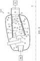
- FIG. 2 illustrates an assembly 60 of the turbine engine 20.
- the turbine engine assembly 60 includes a combustor 62 disposed within an annular plenum 64 of the combustor section 30. This plenum 64 receives compressed core air from the HPC section 29B, and provides the received core air to the combustor 62 as described below in further detail.
- the turbine engine assembly 60 also includes one or more fuel injector assemblies 66.
- Each fuel injector assembly 66 may include a fuel injector 68 mated with a swirler 70.
- the fuel injector 68 injects the fuel into the combustion chamber 56.
- the swirler 70 directs some of the core air from the plenum 64 into the combustion chamber 56 in a manner that facilitates mixing the core air with the injected fuel.
- One or more igniters (not shown) ignite the fuel-core air mixture.
- Quench apertures 72 (see also FIG. 3 ) in walls 74 and 76 of the combustor 62 direct additional core air into the combustion chamber 56 to quench the ignited fuel-core air mixture to become, for example, stoichiometrically lean.
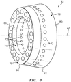
- the combustor 62 may be configured as an annular floating wall combustor as illustrated in FIG. 3 .
- the combustor 62 of FIG. 2 and 3 for example, includes an annular combustor bulkhead 78, the tubular combustor inner wall 74, and the tubular combustor outer wall 76.
- the bulkhead 78 extends vertically (e.g., radially) between and is connected to the inner wall 74 and the outer wall 76.
- the inner wall 74 and the outer wall 76 each extends longitudinally (e.g., axially) along the centerline 22 from the bulkhead 78 towards the HPT section 31A, thereby defining the combustion chamber 56.
- Each of the combustor walls 74 and 76 may be a multi-walled structure; e.g., a hollow dual-walled structure.
- Each combustor wall 74, 76 of FIG. 2 includes a tubular combustor shell 80 and a tubular combustor heat shield 82 with one or more cooling cavities 84-86 (e.g., impingement cavities) between the shell 80 and the heat shield 82.
- Each combustor wall 74, 76 may also include one or more annular quench aperture bodies 88 (e.g., quench aperture grommets). These quench aperture bodies 88 are disposed circumferentially around the centerline 22. Each quench aperture body 88 partially or completely defines a respective one of the quench apertures 72.
- the shell 80 extends circumferentially around the centerline 22.
- the shell 80 extends longitudinally along the centerline 22 between an upstream and forward end 90 and a downstream and aft end 92.
- the shell 80 is connected to the bulkhead 78 at the forward end 90.
- the shell 80 may be connected to a stator vane assembly 94 or the HPT section 31A at the aft end 92.
- the shell 80 has an exterior surface 96, an interior surface 98, one or more aperture surfaces 100 (see FIG. 5 ), one or more aperture surfaces 102 (see FIG. 6 ), and one or more aperture surfaces 104 (see FIG. 6 ). At least a portion of the shell 80 extends vertically between the shell exterior surface 96 and the shell interior surface 98.
- the shell exterior surface 96 which may also be referred to as a plenum surface, defines a portion of a boundary of the plenum 64.
- the shell interior surface 98 which may also be referred to as a cavity surface, defines a portion of a boundary of one or more of the cooling cavities 84-86 (see also FIG. 2 ).
- the aperture surfaces 100 may be arranged in one or more arrays disposed along the centerline 22.
- the aperture surfaces 100 in each array may be arranged circumferentially around the centerline 22.
- Each of the aperture surfaces 100 defines a cooling aperture 106 (see also FIG. 4 ).
- This cooling aperture 106 extends vertically through the shell 80 from the shell exterior surface 96 to the shell interior surface 98.
- the cooling aperture 106 may be configured as an impingement aperture.
- Each aperture surface 100 of FIG. 5 for example, is configured to direct a jet of cooling air to impinge (e.g., substantially perpendicularly) against the heat shield 82.
- the aperture surfaces 102 may be arranged in one or more arrays disposed along the centerline 22.
- the aperture surfaces 102 in each array may be arranged circumferentially around the centerline 22.
- Each of the aperture surfaces 102 defines a cooling aperture 108 (see also FIG. 4 ).
- This cooling aperture 108 extends vertically through the shell 80 from the shell exterior surface 96 to the shell interior surface 98.
- the cooling aperture 108 may be configured as an impingement aperture.
- Each aperture surface 102 of FIG. 6 for example, is configured to direct a jet of cooling air to impinge (e.g., substantially perpendicularly) against the heat shield 82.
- the aperture surfaces 104 may be arranged circumferentially around the centerline 22 in an array. Each aperture surface 104 defines an aperture 110. This aperture 110 extends vertically through the shell 80 from the shell exterior surface 96 to the shell interior surface 98.
- the aperture surface 104 of FIG. 6 is configured such that the aperture 110 may be aligned with an aperture 112 defined by a respective one of the quench aperture bodies 88, where the apertures 110 and 112 may collectively form a respective one of the quench apertures 72.
- the aperture surface 104 may be configured such that the aperture 110 receives a respective one of the quench aperture bodies 88.
- the heat shield 82 extends circumferentially around the centerline 22.
- the heat shield 82 extends longitudinally along the centerline 22 between an upstream and forward end and a downstream and aft end.
- the forward end is located at an interface between the combustor wall 74, 76 and the bulkhead 78.
- the aft end may be located at an interface between the combustor wall 74, 76 and the stator vane assembly 94 and/or the HPT section 31A.
- the heat shield 82 includes a plurality of panel arrays 114 and 116 sequentially arranged along the centerline 22. Each of these panel arrays 114 and 116 respectively includes a plurality of panels 118 and 120. The panels 118, 120 in each array 114, 116 are disposed circumferentially around the centerline 22 and generally form a hoop.
- the heat shield 82 may also or alternatively be configured from a plurality of tubular panels sequentially arranged along the centerline 22; e.g., one or more of the panel arrays 114 and/or 116 may each be replaced with a tubular body.
- each of the panels 118 has one or more interior surfaces 122 and 124 and an exterior surface 126. At least a portion of the panel 118 extends vertically between the interior surfaces 122 and 124 and the exterior surface 126.
- Each interior surface 122 which may also be referred to as a cavity surface, defines a portion of a boundary of a respective one of the cooling cavities 84.
- Each interior surface 124 which may also be referred to as a cavity surface, defines a portion of a boundary of a respective one of the cooling cavities 85.
- the exterior surface 126 which may also be referred to as a chamber surface, defines a portion of a border of the combustion chamber 56.
- Each panel 118 includes a panel base 128 and one or more panel rails 130-134.
- the panel base 128 and the panel rails 130 and 132-134 may collectively define the interior surface 122.
- the panel base 128 and the panel rails 131-134 may collectively define the interior surface 124.
- the panel base 128 may define the exterior surface 126.
- the panel base 128 may be configured as a generally curved (e.g., arcuate) plate.
- the panel base 128 extends longitudinally between a longitudinal forward end 136 and a longitudinal aft end 138.
- the panel base 128 extends laterally (e.g., circumferentially) between opposing lateral ends 140 and 142.
- the panel rails may include one or more longitudinal end rails 130 and 131 and one more lateral end rails 132 and 133.
- the panel rails also include at least one longitudinal intermediate rail 134.
- Each of the panel rails 130-134 of the inner wall 74 extends vertically in from the respective panel base 128; see FIG. 2 .
- Each of the panel rails 130-134 of the outer wall 76 extends vertically out from the respective panel base 128; see FIG. 2 .
- the end and intermediate rails 130, 131 and 134 extend laterally between and are connected to the end rails 132 and 133.
- the end rail 130 is arranged at (e.g., on, adjacent or proximate) the forward end 136.
- the end rail 131 is arranged at the aft end 138.
- the intermediate rail 134 is disposed longitudinally (e.g., approximately midway) between the end rails 130 and 131.
- the end rail 132 is arranged at the lateral end 140.
- the end rail 133 is arranged at the lateral end 142.
- Each of the panels 118 also includes one or more aperture surfaces 144, one or more aperture surfaces 146 and one or more aperture surfaces 148.
- the aperture surfaces 144 may be arranged in one or more arrays disposed along the centerline 22.
- the aperture surfaces 144 in each array may be disposed partially about the centerline 22.
- Each of the aperture surfaces 144 defines a cooling aperture 150 (see also FIG. 4 ).
- This cooling aperture 150 extends vertically through the panel base 128 from an inlet in the panel interior surface 122 to an outlet in the panel exterior surface 126.
- the cooling aperture 150 may be configured as an effusion aperture.
- Each aperture surface 144 may extend along a centerline that is acutely angled (e.g., between about 20° and 45°) relative to one or more of the surfaces 122 and 126.
- the aperture surfaces 146 may be disposed partially about the centerline 22 in an array.
- Each of the aperture surfaces 146 defines a cooling aperture 152 (see also FIG. 4 ); e.g., a laterally elongated slot.
- This cooling aperture 152 extends vertically through the panel base 128 from an inlet 154 in the panel interior surface 124 to an outlet 156 (e.g., a laterally elongated outlet) in the panel exterior surface 126.
- the cooling aperture 152 may be configured as an effusion aperture.
- Each aperture surface 146 may be longitudinally forward and upstream of and approximately laterally aligned with a respective one of the quench apertures 72 as illustrated in FIG. 7 .
- Each aperture surface 146 may extend along a centerline that is acutely angled (e.g., between about 20° and 45°) relative to one or more of the surfaces 124 and 126.
- the aperture surfaces 148 may be disposed partially about the centerline 22 in an array.
- Each of the aperture surfaces 148 defines a cooling aperture 158 (see also FIG. 4 ); e.g., a laterally elongated slot.
- This cooling aperture 158 extends vertically through the panel base 128 from an inlet 160 in the panel interior surface 124 to an outlet 162 (e.g., a laterally elongated outlet) in the panel exterior surface 126.
- the cooling aperture 158 may be configured as an effusion aperture.
- Each aperture surface 148 may be longitudinally forward and upstream of and laterally offset from a respective on of the aperture surfaces 146 and, thus, a respective one of the quench apertures 72 as illustrated in FIG. 7 . In this manner, the film of cooling air discharged from the outlet 162 may be superimposed with the film of cooling air discharged from the respective outlet 156 and flow towards the respective quench aperture 72 where, for example, the core air moves circumferentially within the combustion chamber 56.
- Each aperture surface 148 may extend along a centerline that is acutely angled (e.g., between about 20° and 45°) relative to one or more of the surfaces 124 and 126.
- Each of the quench aperture bodies 88 may be formed integral with (or attached to) a respective one of the panel bases 128.
- One or more of the quench aperture bodies 88 are located laterally within and extend vertically through a respective one of the cooling cavities 85.
- One or more of the quench aperture bodies 88 may be arranged laterally between the lateral end rails 132 and 133 of a respective one of the panels 118.
- One or more of the quench aperture bodies 88 may be arranged longitudinally between the end and intermediate rails 131 and 134 of a respective one of the panels 118.
- Each quench aperture body 88 extends vertically from the panel base 128 to a distal end surface 164.
- the quench aperture body 88 extends laterally between a body outer surface 166 and a body inner surface 168, which at least partially defines a respective one of the quench apertures 72 in the combustor wall 74, 76.
- the body inner surface 168 may be aligned with a respective one of the aperture surfaces 104 and defines the aperture 112, which extends vertically through the panel 118 from the end surface 164 to the exterior surface 126.
- the heat shield 82 of the inner wall 74 circumscribes the shell 80 of the inner wall 74, and defines an inner side of the combustion chamber 56.
- the heat shield 82 of the outer wall 76 is arranged radially within the shell 80 of the outer wall 76, and defines an outer side of the combustion chamber 56 that is opposite the inner side.
- the heat shield 82 is attached to the respective shell 80 thereby forming the cooling cavities 84-86 in each combustor wall 74, 76.
- the panels 118 and 120 may be respectively fastened to the shells by a plurality of mechanical attachments. These mechanical attachments are not shown in the drawings for ease of illustration. However, various mechanical attachments are known in the art and the present invention is not limited to any particular type or configuration thereof.
- the heat shield 82 may also or alternatively be bonded to the shell 80.
- each of the cooling cavities 84 fluidly couples one or more of the cooling apertures 106 with one or more of the cooling apertures 150 and their outlets.
- Each cooling cavity 84 for example, is defined and extends longitudinally between the end and intermediate rails 130 and 134 a respective one of the panels 118.
- Each cooling cavity 84 is defined and extends laterally between the end rails 132 and 133 of a respective one of the panels 118.
- each cooling cavity 84 extends vertically between the interior surface 98 and the interior surface 122 of a respective one of the panels 118, thereby defining a vertical height 170 of the cooling cavity 84.
- This height 170 may change (e.g., increase) as the heat shield 82 extends longitudinally approximately from the end rail 130 to the intermediate rail 134.
- the height 170 adjacent the end rail 130 may be less than (e.g., between about 1/2 to 1/16) the height 170 adjacent the intermediate rail 143.
- Each cooling cavity 84 therefore may have a vertically tapered geometry.
- the cooling cavity tapered geometry may be defined by respective opposing portions of the shell 80 and the heat shield 82. These shell and heat shield portions, for example, may vertically converge towards one another as the combustor wall 74, 76 extends in a forward and upstream direction.
- the thickness of the shell 80 more particularly, may increase as the combustor wall 74, 76 extends in the forward and upstream direction.
- each of the cooling cavities 85 fluidly couples one or more of the cooling apertures 108 with one or more of the cooling apertures 152 and 158 and their outlets 156 and 162.
- Each cooling cavity 85 for example, is defined and extends longitudinally between the intermediate and end rails 131 and 134 a respective one of the panels 118.
- Each cooling cavity 85 is defined and extends laterally between the end rails 132 and 133 of a respective one of the panels 118.
- Each cooling cavity 85 extends vertically between the interior surface 98 and the interior surface 124 of a respective one of the panels 118, thereby defining a vertical height 172 (see FIG. 6 ) of the cooling cavity 85. This height 172 may be substantially constant as the heat shield 82 extends longitudinally between the end and intermediate rails 131 and 134.
- the shell 80 directs core air from the plenum 64 into each cooling cavity 84 through the respective cooling apertures 106.
- This core air e.g., cooling air
- impinges against and thereby impingement cools respective portions of the heat shield panels 118 proximate the intermediate rail 134.
- the cooling air within each cooling cavity 84 is accelerated towards the cooling apertures 150 and the end rail 134 by the converging interior surfaces 98 and 122.
- the heat shield 82 subsequently directs (e.g., effuses) the accelerated cooling air out of the combustor wall 74, 76 through the cooling apertures 150 and into the combustion chamber 56 to film cool downstream portions of the respective heat shield panel 118.
- Downstream portions of the heat shield panels 118 may be subject to higher core air temperatures within the combustion chamber 56 than upstream portions of the heat shield panels 118.
- the combustor wall 74, 76 may accommodate this temperature differential, however, since the shell 80 directs the core air to impinge against the heat shield 82 proximate the intermediate rail 134. Portions of each heat shield panel 118 proximate the intermediate rail 134 therefore receives additional cooling as compared to portions of the heat shield panel 118 proximate the end rail 130.
- the combustor wall 74, 76 may utilize less of the core air within the plenum 64 for cooling and thereby increase engine efficiency.
- the shell 80 also directs core air from the plenum 64 into each cooling cavity 85 through the respective cooling apertures 108.
- This core air e.g., cooling air
- the heat shield 82 subsequently directs (e.g., effuses) the cooling air out of the combustor wall 74, 76 through the cooling apertures 152 and 158 and into the combustion chamber 56 to film cool downstream portions of the heat shield 82; e.g., the respective heat shield panel 118.
- the cooling air discharged from each cooling aperture 154, 158 may form an air blanket against the exterior surface 126 that flows along a longitudinal path towards a respective one of the quench apertures 72.
- This air blanket may provide a thermal barrier between portions of the heat shield 82 adjacent and/or proximate the quench aperture 72 and the relatively hot core air within the combustion chamber 56.
- the air blanket may also convectively cool the respective portion(s) of the heat shield 82.
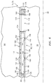
- one or more of the combustor walls 74 and 76 may each be configured to provide one or more of the cavities 85 with a tapered geometry.
- the vertical height 172 may change (e.g., decrease) as the heat shield 82 extends longitudinally approximately from the intermediate rail 134 to the end rail 131.
- the height 172 at the quench aperture body 88 may be less than (e.g., between about 1/2 to 1/16) the height 172 adjacent the intermediate rail 134.
- the cooling cavity 85 tapered geometry may be defined by respective opposing portions of the shell 80 and the heat shield 82. These shell and heat shield portions, for example, may vertically converge towards one another as the combustor wall 74, 76 extends in an aft and downstream direction. The thickness of the shell 80, for example, may increase as the combustor wall 74, 76 extends in the aft and downstream direction.
- one or more of the combustor walls 74 and 76 may each be configured to provide one or more of the cavities 84 with a non-tapered geometry as illustrated in FIG. 9 .
- the vertical height 170 may be substantially constant as the heat shield 82 extends between the longitudinal end and intermediate rails 130 and 134.
- the thickness of the shell 80 may be substantially constant.
- one or more of the outlets 156, 162 may each be collectively formed by a plurality of respective aperture surfaces 174, 176 and cooling apertures 178, 180 defined thereby. More particularly, respective cooling aperture outlets 182 formed by a subset of the aperture surfaces 174 may collectively form the respective elongated outlet 156. Similarly, cooling aperture outlets 184 formed by a subset of the aperture surfaces 176 may collectively form the respective elongated outlet 162.
- One or more of the combustor walls 74 and 76 may each have different configurations other than those described above.
- the heat shield 82 may also or alternatively have a changing thickness to provide one or more of the cavities 84 and/or 85 with its tapered geometry.
- the shell 80 and/or the heat shield 82 may each include a curved and/or compound concavity to provide one or more of the cavities 84 and/or 85 with its tapered geometry.
- One or more cavities may be defined longitudinally between the cavities 84 and 85.
- One or more of the cooling apertures may have cross-sectionals other than those described above and illustrated in the figures.
- one or more of the cooling apertures may each have a circular or non-circular cross-section.
- non-circular cross-section examples include, but are not limited to, an oval cross-section, an elliptical cross-section, a pear-shaped cross-section, a teardrop cross-section, a polygonal (e.g., rectangular) cross-section, or any other symmetric or asymmetric shaped cross-section with, for example, its major axis aligned (e.g., parallel) with the centerline 22.
- the turbine engine assembly 60 may be included in various turbine engines other than the one described above.
- the turbine engine assembly 60 for example, may be included in a geared turbine engine where a gear train connects one or more shafts to one or more rotors in a fan section, a compressor section and/or any other engine section.
- the turbine engine assembly 60 may be included in a turbine engine configured without a gear train.
- the turbine engine assembly 60 may be included in a geared or non-geared turbine engine configured with a single spool, with two spools (e.g., see FIG. 1 ), or with more than two spools.
- the turbine engine may be configured as a turbofan engine, a turbojet engine, a propfan engine, or any other type of turbine engine. The present invention therefore is not limited to any particular types or configurations of turbine engines.
- the term “at” may be used above to locate a respective component / element relative to another component / element or location. Unless stated otherwise, the term “at” may encompass the terms “on”, “adjacent” and “proximate”. For example, a component described above as being located at an end of another component may be located on, adjacent or proximate the end of the other component.
Landscapes
- Engineering & Computer Science (AREA)
- Chemical & Material Sciences (AREA)
- Combustion & Propulsion (AREA)
- Mechanical Engineering (AREA)
- General Engineering & Computer Science (AREA)
- Turbine Rotor Nozzle Sealing (AREA)
Claims (4)
- Ensemble pour un moteur à turbine, l'ensemble comprenant :une paroi de chambre de combustion (74, 76) comportant une coque (80) et un écran thermique (82) comportant des panneaux (118, 120) d'écran thermique et l'un des panneaux (118) d'écran thermique définit une première sortie (150) et une deuxième sortie allongée (156), et dans lequel la paroi de chambre de combustion définit une ouverture de trempe (72) à travers la coque (80) et le panneau (118), caractérisé par la paroi de chambre de combustion (74, 76) définissant des première et seconde cavités (84, 85) entre la coque (80) et le panneau (118) ;dans lequel la première sortie (150) est couplée fluidiquement à la première cavité (84), et la seconde sortie (156) est couplée fluidiquement à la seconde cavité (85) ;dans lequel la paroi de chambre de combustion (74, 76) définit la première cavité (84) avec une géométrie effilée, dans lequel la coque (80) et le panneau (118) convergent l'un vers l'autre définissant ainsi au moins partiellement la première cavité (84) avec la géométrie effilée,dans lequel la deuxième sortie (156) est définie par une ou plusieurs surfaces d'ouverture (146) configurées pour acheminer un film d'air de refroidissement dans la chambre de combustion (56) afin de refroidir par film une partie aval du panneau adjacent à l'ouverture de trempe (72),dans lequel les première et seconde cavités (84, 85) sont séparées fluidiquement par un rail (134), et la paroi de chambre de combustion (72, 74) est configurée pour accélérer l'air à l'intérieur de la première cavité (84) à l'écart du rail (134) par la coque (80) convergente et le panneau (118), dans lequel la coque (80) comprend une ou plusieurs ouvertures (106) à travers celle-ci et configurées pour projeter l'air contre des parties du panneau (118) à proximité du rail (134).
- Ensemble selon la revendication 1, dans lequel le panneau (118) définit une troisième sortie (162) couplée fluidiquement à la seconde cavité (85), et est configuré pour acheminer de l'air de refroidissement supplémentaire de la seconde cavité (85) à travers la troisième sortie (162) et vers l'ouverture de trempe (72).
- Ensemble selon la revendication 2, dans lequel les deuxième et troisième sorties (156, 162) sont décalées.
- Ensemble selon la revendication 1, 2 ou 3, dans lequel le panneau (118) définit une pluralité d'ouvertures (180) à travers celui-ci qui forme au moins partiellement la deuxième sortie allongée (156).
Applications Claiming Priority (2)
| Application Number | Priority Date | Filing Date | Title |
|---|---|---|---|
| US201461935146P | 2014-02-03 | 2014-02-03 | |
| PCT/US2015/014277 WO2015117137A1 (fr) | 2014-02-03 | 2015-02-03 | Refroidissement par film d'air d'une paroi de chambre de combustion d'un moteur à turbine |
Publications (3)
| Publication Number | Publication Date |
|---|---|
| EP3102883A1 EP3102883A1 (fr) | 2016-12-14 |
| EP3102883A4 EP3102883A4 (fr) | 2017-03-01 |
| EP3102883B1 true EP3102883B1 (fr) | 2020-04-01 |
Family
ID=53757837
Family Applications (1)
| Application Number | Title | Priority Date | Filing Date |
|---|---|---|---|
| EP15743044.8A Active EP3102883B1 (fr) | 2014-02-03 | 2015-02-03 | Refroidissement par film d'air d'une paroi de chambre de combustion d'un moteur à turbine |
Country Status (3)
| Country | Link |
|---|---|
| US (2) | US10533745B2 (fr) |
| EP (1) | EP3102883B1 (fr) |
| WO (1) | WO2015117137A1 (fr) |
Families Citing this family (8)
| Publication number | Priority date | Publication date | Assignee | Title |
|---|---|---|---|---|
| WO2015085081A1 (fr) * | 2013-12-06 | 2015-06-11 | United Technologies Corporation | Refroidissement de bouclier thermique de chambre de combustion à proximité d'une ouverture de refroidissement rapide |
| AU2016390428C1 (en) * | 2016-01-29 | 2022-07-28 | Skinprotect Corporation Sdn Bhd | Elastomeric articles, compositions, and methods for their production |
| RU2761262C2 (ru) * | 2017-12-26 | 2021-12-06 | Ансальдо Энергия Свитзерленд Аг | Трубчатая камера сгорания для газовой турбины и газовая турбина, содержащая такую трубчатую камеру сгорания |
| US20190219266A1 (en) * | 2018-01-12 | 2019-07-18 | United Technologies Corporation | Apparatus and method for mitigating particulate accumulation on a component of a gas turbine |
| US10816213B2 (en) | 2018-03-01 | 2020-10-27 | General Electric Company | Combustor assembly with structural cowl and decoupled chamber |
| US11029031B2 (en) | 2018-08-02 | 2021-06-08 | Raytheon Technologies Corporation | Tapered panel rail |
| EP4006306B1 (fr) * | 2020-11-27 | 2024-05-15 | Ansaldo Energia Switzerland AG | Conduit de transition pour une chambre de combustion de turbine à gaz |
| CN116772238A (zh) | 2022-03-08 | 2023-09-19 | 通用电气公司 | 圆顶-导流器接头冷却布置 |
Family Cites Families (58)
| Publication number | Priority date | Publication date | Assignee | Title |
|---|---|---|---|---|
| DE1957147A1 (de) * | 1968-11-15 | 1970-06-04 | Rolls Royce | Flammrohr fuer Verbrennungsanlagen von Gasturbinentriebwerken |
| US3572031A (en) * | 1969-07-11 | 1971-03-23 | United Aircraft Corp | Variable area cooling passages for gas turbine burners |
| US4292810A (en) * | 1979-02-01 | 1981-10-06 | Westinghouse Electric Corp. | Gas turbine combustion chamber |
| US4265085A (en) | 1979-05-30 | 1981-05-05 | United Technologies Corporation | Radially staged low emission can-annular combustor |
| US4242871A (en) * | 1979-09-18 | 1981-01-06 | United Technologies Corporation | Louver burner liner |
| US4302941A (en) * | 1980-04-02 | 1981-12-01 | United Technologies Corporation | Combuster liner construction for gas turbine engine |
| US4567730A (en) * | 1983-10-03 | 1986-02-04 | General Electric Company | Shielded combustor |
| US4628694A (en) | 1983-12-19 | 1986-12-16 | General Electric Company | Fabricated liner article and method |
| JPH0660740B2 (ja) * | 1985-04-05 | 1994-08-10 | 工業技術院長 | ガスタービンの燃焼器 |
| FR2599821B1 (fr) | 1986-06-04 | 1988-09-02 | Snecma | Chambre de combustion pour turbomachines a orifices de melange assurant le positionnement de la paroi chaude sur la paroi froide |
| US5083422A (en) * | 1988-03-25 | 1992-01-28 | General Electric Company | Method of breach cooling |
| US5307637A (en) * | 1992-07-09 | 1994-05-03 | General Electric Company | Angled multi-hole film cooled single wall combustor dome plate |
| US5261223A (en) * | 1992-10-07 | 1993-11-16 | General Electric Company | Multi-hole film cooled combustor liner with rectangular film restarting holes |
| US5687572A (en) * | 1992-11-02 | 1997-11-18 | Alliedsignal Inc. | Thin wall combustor with backside impingement cooling |
| JP3415663B2 (ja) * | 1992-12-28 | 2003-06-09 | アルストム | 冷却面を衝撃式に冷却するための装置 |
| US5461866A (en) | 1994-12-15 | 1995-10-31 | United Technologies Corporation | Gas turbine engine combustion liner float wall cooling arrangement |
| GB2298267B (en) * | 1995-02-23 | 1999-01-13 | Rolls Royce Plc | An arrangement of heat resistant tiles for a gas turbine engine combustor |
| US5758503A (en) | 1995-05-03 | 1998-06-02 | United Technologies Corporation | Gas turbine combustor |
| FR2735561B1 (fr) * | 1995-06-14 | 1997-07-18 | Snecma | Chambre de combustion comportant une paroi annulaire multiperforee |
| DE19612840A1 (de) | 1996-03-30 | 1997-10-02 | Abb Research Ltd | Vorrichtung und Verfahren zur Kühlung einer einseitig von Heissgas umgebenen Wand |
| US5758504A (en) * | 1996-08-05 | 1998-06-02 | Solar Turbines Incorporated | Impingement/effusion cooled combustor liner |
| GB2326706A (en) * | 1997-06-25 | 1998-12-30 | Europ Gas Turbines Ltd | Heat transfer structure |
| GB2328011A (en) * | 1997-08-05 | 1999-02-10 | Europ Gas Turbines Ltd | Combustor for gas or liquid fuelled turbine |
| DE59903399D1 (de) * | 1998-03-19 | 2002-12-19 | Siemens Ag | Wandsegment für einen brennraum sowie brennraum |
| CA2288557C (fr) * | 1998-11-12 | 2007-02-06 | Mitsubishi Heavy Industries, Ltd. | Montage de refroidissement de chambre de combustion a turbine a gaz |
| GB9926257D0 (en) * | 1999-11-06 | 2000-01-12 | Rolls Royce Plc | Wall elements for gas turbine engine combustors |
| FR2804405B1 (fr) | 2000-01-28 | 2002-05-10 | Schmalbach Lubeca | Procede et appareil de stockage de preformes plastiques dans un container, procede et installation de fabrication et de stockage de preformes plastiques |
| GB2373319B (en) * | 2001-03-12 | 2005-03-30 | Rolls Royce Plc | Combustion apparatus |
| US7093439B2 (en) * | 2002-05-16 | 2006-08-22 | United Technologies Corporation | Heat shield panels for use in a combustor for a gas turbine engine |
| EP1482246A1 (fr) * | 2003-05-30 | 2004-12-01 | Siemens Aktiengesellschaft | Chambre de combustion |
| US7146815B2 (en) | 2003-07-31 | 2006-12-12 | United Technologies Corporation | Combustor |
| EP1650503A1 (fr) | 2004-10-25 | 2006-04-26 | Siemens Aktiengesellschaft | Méthode de refroidissement d'un bouclier thermique et bouclier thermique |
| GB0601418D0 (en) * | 2006-01-25 | 2006-03-08 | Rolls Royce Plc | Wall elements for gas turbine engine combustors |
| EP1813869A3 (fr) * | 2006-01-25 | 2013-08-14 | Rolls-Royce plc | Éléments de paroi de chambre de combustion de turbine à gaz |
| DE102006026969A1 (de) * | 2006-06-09 | 2007-12-13 | Rolls-Royce Deutschland Ltd & Co Kg | Gasturbinenbrennkammerwand für eine mager-brennende Gasturbinenbrennkammer |
| GB2441342B (en) * | 2006-09-01 | 2009-03-18 | Rolls Royce Plc | Wall elements with apertures for gas turbine engine components |
| DE102007018061A1 (de) * | 2007-04-17 | 2008-10-23 | Rolls-Royce Deutschland Ltd & Co Kg | Gasturbinenbrennkammerwand |
| US20100095680A1 (en) * | 2008-10-22 | 2010-04-22 | Honeywell International Inc. | Dual wall structure for use in a combustor of a gas turbine engine |
| US20100095679A1 (en) * | 2008-10-22 | 2010-04-22 | Honeywell International Inc. | Dual wall structure for use in a combustor of a gas turbine engine |
| US8266914B2 (en) * | 2008-10-22 | 2012-09-18 | Pratt & Whitney Canada Corp. | Heat shield sealing for gas turbine engine combustor |
| US8910481B2 (en) | 2009-05-15 | 2014-12-16 | United Technologies Corporation | Advanced quench pattern combustor |
| US8739546B2 (en) | 2009-08-31 | 2014-06-03 | United Technologies Corporation | Gas turbine combustor with quench wake control |
| US8443610B2 (en) | 2009-11-25 | 2013-05-21 | United Technologies Corporation | Low emission gas turbine combustor |
| US9068751B2 (en) | 2010-01-29 | 2015-06-30 | United Technologies Corporation | Gas turbine combustor with staged combustion |
| US9057523B2 (en) * | 2011-07-29 | 2015-06-16 | United Technologies Corporation | Microcircuit cooling for gas turbine engine combustor |
| US8978385B2 (en) | 2011-07-29 | 2015-03-17 | United Technologies Corporation | Distributed cooling for gas turbine engine combustor |
| US9322554B2 (en) | 2011-07-29 | 2016-04-26 | United Technologies Corporation | Temperature mixing enhancement with locally co-swirling quench jet pattern for gas turbine engine combustor |
| GB201116608D0 (en) * | 2011-09-27 | 2011-11-09 | Rolls Royce Plc | A method of operating a combustion chamber |
| US8572983B2 (en) * | 2012-02-15 | 2013-11-05 | United Technologies Corporation | Gas turbine engine component with impingement and diffusive cooling |
| US9052111B2 (en) * | 2012-06-22 | 2015-06-09 | United Technologies Corporation | Turbine engine combustor wall with non-uniform distribution of effusion apertures |
| US9010122B2 (en) * | 2012-07-27 | 2015-04-21 | United Technologies Corporation | Turbine engine combustor and stator vane assembly |
| US9194585B2 (en) * | 2012-10-04 | 2015-11-24 | United Technologies Corporation | Cooling for combustor liners with accelerating channels |
| US9188336B2 (en) * | 2012-10-31 | 2015-11-17 | General Electric Company | Assemblies and apparatus related to combustor cooling in turbine engines |
| WO2014112992A1 (fr) * | 2013-01-16 | 2014-07-24 | United Technologies Corporation | Ensemble zone de trempe refroidi par chambre de combustion |
| WO2014113007A1 (fr) * | 2013-01-17 | 2014-07-24 | United Technologies Corporation | Ensemble revêtement pour chambre de combustion de turbine à gaz équipé d'un profil hyperbolique convergent |
| EP2954261B1 (fr) * | 2013-02-08 | 2020-03-04 | United Technologies Corporation | Chambre de combustion de turbine à gaz |
| US9939154B2 (en) * | 2013-02-14 | 2018-04-10 | United Technologies Corporation | Combustor liners with U-shaped cooling channels |
| US9909761B2 (en) * | 2014-04-09 | 2018-03-06 | United Technologies Corporation | Combustor wall assembly for a turbine engine |
-
2015
- 2015-02-03 WO PCT/US2015/014277 patent/WO2015117137A1/fr active Application Filing
- 2015-02-03 US US15/113,558 patent/US10533745B2/en active Active
- 2015-02-03 EP EP15743044.8A patent/EP3102883B1/fr active Active
-
2019
- 2019-12-04 US US16/703,211 patent/US11320146B2/en active Active
Non-Patent Citations (1)
| Title |
|---|
| None * |
Also Published As
| Publication number | Publication date |
|---|---|
| EP3102883A1 (fr) | 2016-12-14 |
| EP3102883A4 (fr) | 2017-03-01 |
| US10533745B2 (en) | 2020-01-14 |
| US20200109857A1 (en) | 2020-04-09 |
| US20170009988A1 (en) | 2017-01-12 |
| US11320146B2 (en) | 2022-05-03 |
| WO2015117137A1 (fr) | 2015-08-06 |
Similar Documents
| Publication | Publication Date | Title |
|---|---|---|
| US11320146B2 (en) | Film cooling a combustor wall of a turbine engine | |
| EP3077641B1 (fr) | Refroidissement d'un corps à ouverture pour un allumeur d'une paroi de chambre de combustion | |
| EP3102884B1 (fr) | Chemise thermique étagée pour une chambre de combustion de moteur à turbine | |
| EP3077727B1 (fr) | Un ensemble pour un moteur à turbine | |
| US10317079B2 (en) | Cooling an aperture body of a combustor wall | |
| EP3066389B1 (fr) | Bouclier thermique pour chambre de combustion de moteur à turbine doté d'un ou de plusieurs éléments de refroidissement | |
| US10502422B2 (en) | Cooling a quench aperture body of a combustor wall | |
| EP3018418B1 (fr) | Paroi d'une chambre de combustion avec corps d'ouverture comprenant un circuit de refroidissement | |
| US11193672B2 (en) | Combustor quench aperture cooling | |
| EP3591292B1 (fr) | Corps à ouverture de refroidissement rapide pour une chambre de combustion de moteur à turbine | |
| EP3077726B1 (fr) | Refroidissement de bouclier thermique de chambre de combustion à proximité d'une ouverture de refroidissement rapide |
Legal Events
| Date | Code | Title | Description |
|---|---|---|---|
| PUAI | Public reference made under article 153(3) epc to a published international application that has entered the european phase |
Free format text: ORIGINAL CODE: 0009012 |
|
| STAA | Information on the status of an ep patent application or granted ep patent |
Free format text: STATUS: REQUEST FOR EXAMINATION WAS MADE |
|
| 17P | Request for examination filed |
Effective date: 20160905 |
|
| AK | Designated contracting states |
Kind code of ref document: A1 Designated state(s): AL AT BE BG CH CY CZ DE DK EE ES FI FR GB GR HR HU IE IS IT LI LT LU LV MC MK MT NL NO PL PT RO RS SE SI SK SM TR |
|
| AX | Request for extension of the european patent |
Extension state: BA ME |
|
| A4 | Supplementary search report drawn up and despatched |
Effective date: 20170131 |
|
| RIC1 | Information provided on ipc code assigned before grant |
Ipc: F23M 5/08 20060101ALI20170125BHEP Ipc: F02C 7/12 20060101ALI20170125BHEP Ipc: F23M 5/00 20060101AFI20170125BHEP Ipc: F02C 7/24 20060101ALI20170125BHEP Ipc: F23R 3/42 20060101ALI20170125BHEP |
|
| DAX | Request for extension of the european patent (deleted) | ||
| STAA | Information on the status of an ep patent application or granted ep patent |
Free format text: STATUS: EXAMINATION IS IN PROGRESS |
|
| 17Q | First examination report despatched |
Effective date: 20180719 |
|
| GRAP | Despatch of communication of intention to grant a patent |
Free format text: ORIGINAL CODE: EPIDOSNIGR1 |
|
| STAA | Information on the status of an ep patent application or granted ep patent |
Free format text: STATUS: GRANT OF PATENT IS INTENDED |
|
| INTG | Intention to grant announced |
Effective date: 20191010 |
|
| GRAS | Grant fee paid |
Free format text: ORIGINAL CODE: EPIDOSNIGR3 |
|
| GRAA | (expected) grant |
Free format text: ORIGINAL CODE: 0009210 |
|
| STAA | Information on the status of an ep patent application or granted ep patent |
Free format text: STATUS: THE PATENT HAS BEEN GRANTED |
|
| AK | Designated contracting states |
Kind code of ref document: B1 Designated state(s): AL AT BE BG CH CY CZ DE DK EE ES FI FR GB GR HR HU IE IS IT LI LT LU LV MC MK MT NL NO PL PT RO RS SE SI SK SM TR |
|
| REG | Reference to a national code |
Ref country code: GB Ref legal event code: FG4D |
|
| REG | Reference to a national code |
Ref country code: AT Ref legal event code: REF Ref document number: 1251819 Country of ref document: AT Kind code of ref document: T Effective date: 20200415 Ref country code: CH Ref legal event code: EP |
|
| REG | Reference to a national code |
Ref country code: DE Ref legal event code: R096 Ref document number: 602015049840 Country of ref document: DE |
|
| REG | Reference to a national code |
Ref country code: IE Ref legal event code: FG4D |
|
| PG25 | Lapsed in a contracting state [announced via postgrant information from national office to epo] |
Ref country code: BG Free format text: LAPSE BECAUSE OF FAILURE TO SUBMIT A TRANSLATION OF THE DESCRIPTION OR TO PAY THE FEE WITHIN THE PRESCRIBED TIME-LIMIT Effective date: 20200701 |
|
| REG | Reference to a national code |
Ref country code: NL Ref legal event code: MP Effective date: 20200401 |
|
| REG | Reference to a national code |
Ref country code: LT Ref legal event code: MG4D |
|
| PG25 | Lapsed in a contracting state [announced via postgrant information from national office to epo] |
Ref country code: CZ Free format text: LAPSE BECAUSE OF FAILURE TO SUBMIT A TRANSLATION OF THE DESCRIPTION OR TO PAY THE FEE WITHIN THE PRESCRIBED TIME-LIMIT Effective date: 20200401 Ref country code: PT Free format text: LAPSE BECAUSE OF FAILURE TO SUBMIT A TRANSLATION OF THE DESCRIPTION OR TO PAY THE FEE WITHIN THE PRESCRIBED TIME-LIMIT Effective date: 20200817 Ref country code: NO Free format text: LAPSE BECAUSE OF FAILURE TO SUBMIT A TRANSLATION OF THE DESCRIPTION OR TO PAY THE FEE WITHIN THE PRESCRIBED TIME-LIMIT Effective date: 20200701 Ref country code: GR Free format text: LAPSE BECAUSE OF FAILURE TO SUBMIT A TRANSLATION OF THE DESCRIPTION OR TO PAY THE FEE WITHIN THE PRESCRIBED TIME-LIMIT Effective date: 20200702 Ref country code: FI Free format text: LAPSE BECAUSE OF FAILURE TO SUBMIT A TRANSLATION OF THE DESCRIPTION OR TO PAY THE FEE WITHIN THE PRESCRIBED TIME-LIMIT Effective date: 20200401 Ref country code: IS Free format text: LAPSE BECAUSE OF FAILURE TO SUBMIT A TRANSLATION OF THE DESCRIPTION OR TO PAY THE FEE WITHIN THE PRESCRIBED TIME-LIMIT Effective date: 20200801 Ref country code: LT Free format text: LAPSE BECAUSE OF FAILURE TO SUBMIT A TRANSLATION OF THE DESCRIPTION OR TO PAY THE FEE WITHIN THE PRESCRIBED TIME-LIMIT Effective date: 20200401 Ref country code: NL Free format text: LAPSE BECAUSE OF FAILURE TO SUBMIT A TRANSLATION OF THE DESCRIPTION OR TO PAY THE FEE WITHIN THE PRESCRIBED TIME-LIMIT Effective date: 20200401 Ref country code: SE Free format text: LAPSE BECAUSE OF FAILURE TO SUBMIT A TRANSLATION OF THE DESCRIPTION OR TO PAY THE FEE WITHIN THE PRESCRIBED TIME-LIMIT Effective date: 20200401 |
|
| REG | Reference to a national code |
Ref country code: AT Ref legal event code: MK05 Ref document number: 1251819 Country of ref document: AT Kind code of ref document: T Effective date: 20200401 |
|
| PG25 | Lapsed in a contracting state [announced via postgrant information from national office to epo] |
Ref country code: RS Free format text: LAPSE BECAUSE OF FAILURE TO SUBMIT A TRANSLATION OF THE DESCRIPTION OR TO PAY THE FEE WITHIN THE PRESCRIBED TIME-LIMIT Effective date: 20200401 Ref country code: HR Free format text: LAPSE BECAUSE OF FAILURE TO SUBMIT A TRANSLATION OF THE DESCRIPTION OR TO PAY THE FEE WITHIN THE PRESCRIBED TIME-LIMIT Effective date: 20200401 Ref country code: LV Free format text: LAPSE BECAUSE OF FAILURE TO SUBMIT A TRANSLATION OF THE DESCRIPTION OR TO PAY THE FEE WITHIN THE PRESCRIBED TIME-LIMIT Effective date: 20200401 |
|
| PG25 | Lapsed in a contracting state [announced via postgrant information from national office to epo] |
Ref country code: AL Free format text: LAPSE BECAUSE OF FAILURE TO SUBMIT A TRANSLATION OF THE DESCRIPTION OR TO PAY THE FEE WITHIN THE PRESCRIBED TIME-LIMIT Effective date: 20200401 |
|
| REG | Reference to a national code |
Ref country code: DE Ref legal event code: R097 Ref document number: 602015049840 Country of ref document: DE |
|
| PG25 | Lapsed in a contracting state [announced via postgrant information from national office to epo] |
Ref country code: AT Free format text: LAPSE BECAUSE OF FAILURE TO SUBMIT A TRANSLATION OF THE DESCRIPTION OR TO PAY THE FEE WITHIN THE PRESCRIBED TIME-LIMIT Effective date: 20200401 Ref country code: SM Free format text: LAPSE BECAUSE OF FAILURE TO SUBMIT A TRANSLATION OF THE DESCRIPTION OR TO PAY THE FEE WITHIN THE PRESCRIBED TIME-LIMIT Effective date: 20200401 Ref country code: IT Free format text: LAPSE BECAUSE OF FAILURE TO SUBMIT A TRANSLATION OF THE DESCRIPTION OR TO PAY THE FEE WITHIN THE PRESCRIBED TIME-LIMIT Effective date: 20200401 Ref country code: EE Free format text: LAPSE BECAUSE OF FAILURE TO SUBMIT A TRANSLATION OF THE DESCRIPTION OR TO PAY THE FEE WITHIN THE PRESCRIBED TIME-LIMIT Effective date: 20200401 Ref country code: ES Free format text: LAPSE BECAUSE OF FAILURE TO SUBMIT A TRANSLATION OF THE DESCRIPTION OR TO PAY THE FEE WITHIN THE PRESCRIBED TIME-LIMIT Effective date: 20200401 Ref country code: DK Free format text: LAPSE BECAUSE OF FAILURE TO SUBMIT A TRANSLATION OF THE DESCRIPTION OR TO PAY THE FEE WITHIN THE PRESCRIBED TIME-LIMIT Effective date: 20200401 Ref country code: RO Free format text: LAPSE BECAUSE OF FAILURE TO SUBMIT A TRANSLATION OF THE DESCRIPTION OR TO PAY THE FEE WITHIN THE PRESCRIBED TIME-LIMIT Effective date: 20200401 |
|
| PLBE | No opposition filed within time limit |
Free format text: ORIGINAL CODE: 0009261 |
|
| STAA | Information on the status of an ep patent application or granted ep patent |
Free format text: STATUS: NO OPPOSITION FILED WITHIN TIME LIMIT |
|
| PG25 | Lapsed in a contracting state [announced via postgrant information from national office to epo] |
Ref country code: SK Free format text: LAPSE BECAUSE OF FAILURE TO SUBMIT A TRANSLATION OF THE DESCRIPTION OR TO PAY THE FEE WITHIN THE PRESCRIBED TIME-LIMIT Effective date: 20200401 Ref country code: PL Free format text: LAPSE BECAUSE OF FAILURE TO SUBMIT A TRANSLATION OF THE DESCRIPTION OR TO PAY THE FEE WITHIN THE PRESCRIBED TIME-LIMIT Effective date: 20200401 |
|
| 26N | No opposition filed |
Effective date: 20210112 |
|
| PG25 | Lapsed in a contracting state [announced via postgrant information from national office to epo] |
Ref country code: SI Free format text: LAPSE BECAUSE OF FAILURE TO SUBMIT A TRANSLATION OF THE DESCRIPTION OR TO PAY THE FEE WITHIN THE PRESCRIBED TIME-LIMIT Effective date: 20200401 |
|
| PG25 | Lapsed in a contracting state [announced via postgrant information from national office to epo] |
Ref country code: MC Free format text: LAPSE BECAUSE OF FAILURE TO SUBMIT A TRANSLATION OF THE DESCRIPTION OR TO PAY THE FEE WITHIN THE PRESCRIBED TIME-LIMIT Effective date: 20200401 |
|
| REG | Reference to a national code |
Ref country code: BE Ref legal event code: MM Effective date: 20210228 |
|
| PG25 | Lapsed in a contracting state [announced via postgrant information from national office to epo] |
Ref country code: CH Free format text: LAPSE BECAUSE OF NON-PAYMENT OF DUE FEES Effective date: 20210228 Ref country code: LU Free format text: LAPSE BECAUSE OF NON-PAYMENT OF DUE FEES Effective date: 20210203 Ref country code: LI Free format text: LAPSE BECAUSE OF NON-PAYMENT OF DUE FEES Effective date: 20210228 |
|
| PG25 | Lapsed in a contracting state [announced via postgrant information from national office to epo] |
Ref country code: IE Free format text: LAPSE BECAUSE OF NON-PAYMENT OF DUE FEES Effective date: 20210203 |
|
| PG25 | Lapsed in a contracting state [announced via postgrant information from national office to epo] |
Ref country code: BE Free format text: LAPSE BECAUSE OF NON-PAYMENT OF DUE FEES Effective date: 20210228 |
|
| REG | Reference to a national code |
Ref country code: DE Ref legal event code: R081 Ref document number: 602015049840 Country of ref document: DE Owner name: RAYTHEON TECHNOLOGIES CORPORATION (N.D.GES.D.S, US Free format text: FORMER OWNER: UNITED TECHNOLOGIES CORPORATION, FARMINGTON, CONN., US |
|
| PG25 | Lapsed in a contracting state [announced via postgrant information from national office to epo] |
Ref country code: HU Free format text: LAPSE BECAUSE OF FAILURE TO SUBMIT A TRANSLATION OF THE DESCRIPTION OR TO PAY THE FEE WITHIN THE PRESCRIBED TIME-LIMIT; INVALID AB INITIO Effective date: 20150203 |
|
| P01 | Opt-out of the competence of the unified patent court (upc) registered |
Effective date: 20230520 |
|
| PG25 | Lapsed in a contracting state [announced via postgrant information from national office to epo] |
Ref country code: CY Free format text: LAPSE BECAUSE OF FAILURE TO SUBMIT A TRANSLATION OF THE DESCRIPTION OR TO PAY THE FEE WITHIN THE PRESCRIBED TIME-LIMIT Effective date: 20200401 |
|
| PG25 | Lapsed in a contracting state [announced via postgrant information from national office to epo] |
Ref country code: MK Free format text: LAPSE BECAUSE OF FAILURE TO SUBMIT A TRANSLATION OF THE DESCRIPTION OR TO PAY THE FEE WITHIN THE PRESCRIBED TIME-LIMIT Effective date: 20200401 |
|
| PGFP | Annual fee paid to national office [announced via postgrant information from national office to epo] |
Ref country code: DE Payment date: 20240123 Year of fee payment: 10 Ref country code: GB Payment date: 20240123 Year of fee payment: 10 |
|
| PGFP | Annual fee paid to national office [announced via postgrant information from national office to epo] |
Ref country code: FR Payment date: 20240123 Year of fee payment: 10 |