EP2954261B1 - Chambre de combustion de turbine à gaz - Google Patents
Chambre de combustion de turbine à gaz Download PDFInfo
- Publication number
- EP2954261B1 EP2954261B1 EP14801039.0A EP14801039A EP2954261B1 EP 2954261 B1 EP2954261 B1 EP 2954261B1 EP 14801039 A EP14801039 A EP 14801039A EP 2954261 B1 EP2954261 B1 EP 2954261B1
- Authority
- EP
- European Patent Office
- Prior art keywords
- heat shield
- combustor
- gas turbine
- cantilevered members
- turbine engine
- Prior art date
- Legal status (The legal status is an assumption and is not a legal conclusion. Google has not performed a legal analysis and makes no representation as to the accuracy of the status listed.)
- Active
Links
- 238000000034 method Methods 0.000 claims description 3
- 239000007789 gas Substances 0.000 description 20
- 238000001816 cooling Methods 0.000 description 18
- 239000000446 fuel Substances 0.000 description 17
- 238000002485 combustion reaction Methods 0.000 description 10
- 230000000712 assembly Effects 0.000 description 8
- 238000000429 assembly Methods 0.000 description 8
- 238000010790 dilution Methods 0.000 description 5
- 239000012895 dilution Substances 0.000 description 5
- 239000000567 combustion gas Substances 0.000 description 4
- 230000008901 benefit Effects 0.000 description 3
- 230000003068 static effect Effects 0.000 description 3
- PXHVJJICTQNCMI-UHFFFAOYSA-N Nickel Chemical compound [Ni] PXHVJJICTQNCMI-UHFFFAOYSA-N 0.000 description 2
- 230000001133 acceleration Effects 0.000 description 2
- 230000005540 biological transmission Effects 0.000 description 2
- 230000015572 biosynthetic process Effects 0.000 description 2
- 238000006243 chemical reaction Methods 0.000 description 2
- 229930195733 hydrocarbon Natural products 0.000 description 2
- 150000002430 hydrocarbons Chemical class 0.000 description 2
- 230000009467 reduction Effects 0.000 description 2
- 239000004215 Carbon black (E152) Substances 0.000 description 1
- WYTGDNHDOZPMIW-RCBQFDQVSA-N alstonine Natural products C1=CC2=C3C=CC=CC3=NC2=C2N1C[C@H]1[C@H](C)OC=C(C(=O)OC)[C@H]1C2 WYTGDNHDOZPMIW-RCBQFDQVSA-N 0.000 description 1
- 239000000919 ceramic Substances 0.000 description 1
- 238000004891 communication Methods 0.000 description 1
- 230000006835 compression Effects 0.000 description 1
- 238000007906 compression Methods 0.000 description 1
- 239000002826 coolant Substances 0.000 description 1
- 238000012937 correction Methods 0.000 description 1
- 238000011161 development Methods 0.000 description 1
- 229910003460 diamond Inorganic materials 0.000 description 1
- 239000010432 diamond Substances 0.000 description 1
- 238000002347 injection Methods 0.000 description 1
- 239000007924 injection Substances 0.000 description 1
- 230000003993 interaction Effects 0.000 description 1
- 239000000463 material Substances 0.000 description 1
- 239000000203 mixture Substances 0.000 description 1
- 238000012986 modification Methods 0.000 description 1
- 230000004048 modification Effects 0.000 description 1
- 229910052759 nickel Inorganic materials 0.000 description 1
- 238000010791 quenching Methods 0.000 description 1
- 230000004044 response Effects 0.000 description 1
- 239000000779 smoke Substances 0.000 description 1
- 239000000126 substance Substances 0.000 description 1
- 229910000601 superalloy Inorganic materials 0.000 description 1
- 238000012546 transfer Methods 0.000 description 1
- 239000013585 weight reducing agent Substances 0.000 description 1
Images


Classifications
-
- F—MECHANICAL ENGINEERING; LIGHTING; HEATING; WEAPONS; BLASTING
- F23—COMBUSTION APPARATUS; COMBUSTION PROCESSES
- F23R—GENERATING COMBUSTION PRODUCTS OF HIGH PRESSURE OR HIGH VELOCITY, e.g. GAS-TURBINE COMBUSTION CHAMBERS
- F23R3/00—Continuous combustion chambers using liquid or gaseous fuel
- F23R3/42—Continuous combustion chambers using liquid or gaseous fuel characterised by the arrangement or form of the flame tubes or combustion chambers
- F23R3/50—Combustion chambers comprising an annular flame tube within an annular casing
-
- F—MECHANICAL ENGINEERING; LIGHTING; HEATING; WEAPONS; BLASTING
- F23—COMBUSTION APPARATUS; COMBUSTION PROCESSES
- F23R—GENERATING COMBUSTION PRODUCTS OF HIGH PRESSURE OR HIGH VELOCITY, e.g. GAS-TURBINE COMBUSTION CHAMBERS
- F23R3/00—Continuous combustion chambers using liquid or gaseous fuel
- F23R3/002—Wall structures
-
- F—MECHANICAL ENGINEERING; LIGHTING; HEATING; WEAPONS; BLASTING
- F23—COMBUSTION APPARATUS; COMBUSTION PROCESSES
- F23R—GENERATING COMBUSTION PRODUCTS OF HIGH PRESSURE OR HIGH VELOCITY, e.g. GAS-TURBINE COMBUSTION CHAMBERS
- F23R3/00—Continuous combustion chambers using liquid or gaseous fuel
- F23R3/42—Continuous combustion chambers using liquid or gaseous fuel characterised by the arrangement or form of the flame tubes or combustion chambers
- F23R3/60—Support structures; Attaching or mounting means
-
- F—MECHANICAL ENGINEERING; LIGHTING; HEATING; WEAPONS; BLASTING
- F23—COMBUSTION APPARATUS; COMBUSTION PROCESSES
- F23R—GENERATING COMBUSTION PRODUCTS OF HIGH PRESSURE OR HIGH VELOCITY, e.g. GAS-TURBINE COMBUSTION CHAMBERS
- F23R2900/00—Special features of, or arrangements for continuous combustion chambers; Combustion processes therefor
- F23R2900/03042—Film cooled combustion chamber walls or domes
-
- Y—GENERAL TAGGING OF NEW TECHNOLOGICAL DEVELOPMENTS; GENERAL TAGGING OF CROSS-SECTIONAL TECHNOLOGIES SPANNING OVER SEVERAL SECTIONS OF THE IPC; TECHNICAL SUBJECTS COVERED BY FORMER USPC CROSS-REFERENCE ART COLLECTIONS [XRACs] AND DIGESTS
- Y02—TECHNOLOGIES OR APPLICATIONS FOR MITIGATION OR ADAPTATION AGAINST CLIMATE CHANGE
- Y02T—CLIMATE CHANGE MITIGATION TECHNOLOGIES RELATED TO TRANSPORTATION
- Y02T50/00—Aeronautics or air transport
- Y02T50/60—Efficient propulsion technologies, e.g. for aircraft
-
- Y—GENERAL TAGGING OF NEW TECHNOLOGICAL DEVELOPMENTS; GENERAL TAGGING OF CROSS-SECTIONAL TECHNOLOGIES SPANNING OVER SEVERAL SECTIONS OF THE IPC; TECHNICAL SUBJECTS COVERED BY FORMER USPC CROSS-REFERENCE ART COLLECTIONS [XRACs] AND DIGESTS
- Y10—TECHNICAL SUBJECTS COVERED BY FORMER USPC
- Y10T—TECHNICAL SUBJECTS COVERED BY FORMER US CLASSIFICATION
- Y10T29/00—Metal working
- Y10T29/49—Method of mechanical manufacture
- Y10T29/49826—Assembling or joining
- Y10T29/49828—Progressively advancing of work assembly station or assembled portion of work
Definitions
- the present disclosure relates to a gas turbine engine and, more particularly, to a combustor section therefor.
- Gas turbine engines such as those that power modern commercial and military aircraft, generally include a compressor to pressurize an airflow, a combustor for burning a hydrocarbon fuel in the presence of the pressurized air, and a turbine to extract energy from the resultant combustion gases.
- TSFC thrust specific fuel consumption
- CET combustor exit temperatures
- current combustor configurations emissions such as NOx, CO, unburned hydrocarbons (UHC), and smoke, may increase relative to exceedingly stringent emissions standards.
- EP 2946092 A1 is a prior right document and not relevant for the assessment of inventive step.
- Prior art includes US 2007/180828 A1 and US 4843825 A .
- a heat shield for a combustor of a gas turbine engine according to the present invention is claimed in claim 1.
- a further embodiment of any of the foregoing embodiments of the present invention includes interleaved cantilevered members between one of the first heat shield and the second heat shield.
- a further embodiment of any of the foregoing embodiments of the present invention includes an exit splitter that extends from one of the first heat shield or the second heat shield.
- a further embodiment of any of the foregoing embodiments of the present invention includes, wherein the exit splitter is zigzag in shape.
- a further embodiment of any of the foregoing embodiments of the present invention includes, further comprising a film hole located in a valley on each side of the exit splitter.
- a further embodiment of any of the foregoing embodiments of the present invention includes, further comprising a plurality of studs which extend from the one of the first heat shield or the second heat shield, the stud includes a frustro-conical section.
- a further embodiment of any of the foregoing embodiments of the present invention includes, wherein one of the first heat shield or the second heat shield includes a multiple of pin fins.
- a further embodiment of any of the foregoing embodiments of the present invention includes, wherein the multiple of pin fins are diamond-shaped.
- a further embodiment of any of the foregoing embodiments of the present invention includes, wherein one of the first heat shield or the second heat shield includes a multiple of hemi-spherical nubbins.
- a further embodiment of any of the foregoing embodiments of the present invention includes, wherein the multiple of hemi-spherical nubbins decrease in diameter toward an exit splitter.
- a further embodiment of any of the foregoing embodiments of the present invention includes, wherein a center of the sphere of each of the multiple of hemi-spherical nubbins are further displaced from an inner surface of the heat shield toward an exit splitter.
- a method of mounting a liner assembly of a combustor for a gas turbine engine according to the present invention is claimed in claim 7.
- a further embodiment of any of the foregoing embodiments of the present invention includes threading a nut to a stud that extends from the first heat shield to drive a support shell onto the first heat shield.
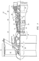
- FIG. 1 schematically illustrates a gas turbine engine 20.
- the gas turbine engine 20 is disclosed herein as a two-spool turbo fan that generally incorporates a fan section 22, a compressor section 24, a combustor section 26 and a turbine section 28.
- Alternative engines might include an augmentor section (not shown) among other systems or features.
- the fan section 22 drives air along a bypass flowpath while the compressor section 24 drives air along a core flowpath for compression and communication into the combustor section 26 then expansion through the turbine section 28.
- turbofan in the disclosed non-limiting embodiment, it should be understood that the concepts described herein are not limited to use with turbofans as the teachings may be applied to other types of turbine engines such as a turbojets, turboshafts, and three-spool (plus fan) turbofans wherein an intermediate spool includes an intermediate pressure compressor ("IPC") between a Low Pressure Compressor (“LPC”) and a High Pressure Compressor (“HPC”), and an intermediate pressure turbine (“IPT”) between the high pressure turbine (“HPT”) and the Low pressure Turbine (“LPT”).
- IPC intermediate pressure compressor
- LPC Low Pressure Compressor
- HPC High Pressure Compressor
- IPT intermediate pressure turbine
- the engine 20 generally includes a low spool 30 and a high spool 32 mounted for rotation about an engine central longitudinal axis A relative to an engine static structure 36 via several bearing structures 38.
- the low spool 30 generally includes an inner shaft 40 that interconnects a fan 42, a low pressure compressor 44 ("LPC") and a low pressure turbine 46 ("LPT").
- the inner shaft 40 drives the fan 42 directly or through a geared architecture 48 to drive the fan 42 at a lower speed than the low spool 30.
- An exemplary reduction transmission is an epicyclic transmission, namely a planetary or star gear system.
- the high spool 32 includes an outer shaft 50 that interconnects a high pressure compressor 52 ("HPC”) and high pressure turbine 54 ("HPT").
- a combustor 56 is arranged between the high pressure compressor 52 and the high pressure turbine 54.
- the inner shaft 40 and the outer shaft 50 are concentric and rotate about the engine central longitudinal axis A which is collinear with their longitudinal axes.
- the main engine shafts 40, 50 are supported at a plurality of points by bearing structures 38 within the static structure 36. It should be understood that various bearing structures 38 at various locations may alternatively or additionally be provided.
- the gas turbine engine 20 is a high-bypass geared aircraft engine.
- the gas turbine engine 20 bypass ratio is greater than about six (6:1).
- the geared architecture 48 can include an epicyclic gear train, such as a planetary gear system or other gear system.
- the example epicyclic gear train has a gear reduction ratio of greater than about 2.3, and in another example is greater than about 2.5:1.
- the geared turbofan enables operation of the low spool 30 at higher speeds which can increase the operational efficiency of the low pressure compressor 44 and low pressure turbine 46 and render increased pressure in a fewer number of stages.
- a pressure ratio associated with the low pressure turbine 46 is pressure measured prior to the inlet of the low pressure turbine 46 as related to the pressure at the outlet of the low pressure turbine 46 prior to an exhaust nozzle of the gas turbine engine 20.
- the bypass ratio of the gas turbine engine 20 is greater than about ten (10:1)
- the fan diameter is significantly larger than that of the low pressure compressor 44
- the low pressure turbine 46 has a pressure ratio that is greater than about five (5:1). It should be understood, however, that the above parameters are only exemplary of one embodiment of a geared architecture engine and that the present disclosure is applicable to other gas turbine engines including direct drive turbofans.
- a significant amount of thrust is provided by the bypass flow path due to the high bypass ratio.
- the fan section 22 of the gas turbine engine 20 is designed for a particular flight condition - typically cruise at about 0.8 Mach and about 35,000 feet. This flight condition, with the gas turbine engine 20 at its best fuel consumption, is also known as bucket cruise Thrust Specific Fuel Consumption (TSFC).
- TSFC Thrust Specific Fuel Consumption
- Fan Pressure Ratio is the pressure ratio across a blade of the fan section 22 without the use of a Fan Exit Guide Vane system.
- the low Fan Pressure Ratio according to one non-limiting embodiment of the example gas turbine engine 20 is less than 1.45.
- Low Corrected Fan Tip Speed is the actual fan tip speed divided by an industry standard temperature correction of ("T" / 518.7) 0.5 in which "T" represents the ambient temperature in degrees Rankine.
- the Low Corrected Fan Tip Speed according to one non-limiting embodiment of the example gas turbine engine 20 is less than about 1150 fps (351 m/s).
- the combustor 56 generally includes an outer combustor liner assembly 60, an inner combustor liner assembly 62 and a diffuser case module 64.
- the outer combustor liner assembly 60 and the inner combustor liner assembly 62 are spaced apart such that a combustion chamber 66 is defined therebetween.
- the combustion chamber 66 is generally annular in shape.
- the outer combustor liner assembly 60 is spaced radially inward from an outer diffuser case 64-O of the diffuser case module 64 to define an outer annular plenum 76.
- the inner combustor liner assembly 62 is spaced radially outward from an inner diffuser case 64-I of the diffuser case module 64 to define an inner annular plenum 78. It should be understood that although a particular combustor is illustrated, other combustor types with various combustor liner arrangements will also benefit herefrom. It should be further understood that the disclosed cooling flow paths are but an illustrated embodiment and should not be limited only thereto.
- the combustor liner assemblies 60, 62 contain the combustion products for direction toward the turbine section 28.
- Each combustor liner assembly 60, 62 generally includes a respective support shell 68, 70 which supports one or more heat shields 72, 74 mounted to a hot side of the respective support shell 68, 70.
- Each of the heat shields 72, 74 may be generally rectilinear and manufactured of, for example, a nickel based super alloy, ceramic or other temperature resistant material and are arranged to form a liner array.
- the liner array includes a multiple of forward heat shields 72A and a multiple of aft heat shields 72B that are circumferentially staggered to line the hot side of the outer shell 68 (also shown in Figure 3 ).
- a multiple of forward heat shields 74A and a multiple of aft heat shields 74B are circumferentially staggered to line the hot side of the inner shell 70 (also shown in Figure 3 ).
- the combustor 56 further includes a forward assembly 80 immediately downstream of the compressor section 24 to receive compressed airflow therefrom.
- the forward assembly 80 generally includes an annular hood 82, a bulkhead assembly 84, a multiple of fuel nozzles 86 (one shown) and a multiple of fuel nozzle pre-swirlers 90 (one shown).
- Each of the fuel nozzle pre-swirlers 90 is circumferentially aligned with one of the hood ports 94 to project through the bulkhead assembly 84.
- Each bulkhead assembly 84 includes a bulkhead support shell 96 secured to the combustor liner assemblies 60, 62, and a multiple of circumferentially distributed bulkhead heat shields 98 secured to the bulkhead support shell 96 around the central opening 92.
- the annular hood 82 extends radially between, and is secured to, the forwardmost ends of the combustor liner assemblies 60, 62.
- the annular hood 82 includes a multiple of circumferentially distributed hood ports 94 that accommodate the respective fuel nozzle 86 and introduce air into the forward end of the combustion chamber 66 through a central opening 92.
- Each fuel nozzle 86 may be secured to the diffuser case module 64 and project through one of the hood ports 94 and through the central opening 92 within the respective fuel nozzle guide 90.
- the forward assembly 80 introduces core combustion air into the forward section of the combustion chamber 66 while the remainder enters the outer annular plenum 76 and the inner annular plenum 78.
- the multiple of fuel nozzles 86 and adjacent structure generate a blended fuel-air mixture that supports stable combustion in the combustion chamber 66.
- the outer and inner support shells 68, 70 are mounted to a first row of Nozzle Guide Vanes (NGVs) 54A in the HPT 54.
- the NGVs 54A are static engine components which direct core airflow combustion gases onto the turbine blades of the first turbine rotor in the turbine section 28 to facilitate the conversion of chemical energy into kinetic energy.
- the core airflow combustion gases are also accelerated by the NGVs 54A because of their convergent shape and are typically given a "spin” or a "swirl” in the direction of turbine rotor rotation.
- the turbine rotor blades absorb this energy to drive the turbine rotor at high speed.
- a multiple of studs 100 extend from the heat shields 72, 74 to mount the heat shields 72, 74 to the respective support shells 68, 70 with fasteners 102 such as nuts (also shown in Figure 3 ). That is, the studs 100 project rigidly from the heat shields 72, 74 and through the respective support shells 68, 70 to receive the fasteners 102 at a threaded distal end section thereof.
- a multiple of cooling impingement holes 104 penetrate through the support shells 68, 70 to allow air from the respective annular plenums 76, 78 to enter cavities 106A, 106B (also shown in Figure 3 ) formed in the combustor liner assemblies 60, 62 between the respective support shells 68, 70 and heat shields 72, 74.
- the cooling impingement holes 104 are generally normal to the surface of the heat shields 72, 74.
- the air in the cavities 106A, 106B provides backside impingement cooling of the heat shields 72, 74 that is generally defined herein as heat removal via internal convection.
- a multiple of cooling film holes 108 penetrate through each of the heat shields 72, 74.
- the geometry of the film holes e.g, diameter, shape, density, surface angle, incidence angle, etc., as well as the location of the holes with respect to the high temperature main flow also contributes to effusion film cooling.
- the combination of impingement holes 104 and film holes 108 may be referred to as an Impingement Film Floatwall liner assembly.
- the cooling film holes 108 allow the air to pass from the cavities 106A, 106B defined in part by a cold side 110 of the heat shields 72, 74 to a hot side 112 of the heat shields 72, 74 and thereby facilitate the formation of a film of cooling air along the hot side 112.
- the cooling film holes 108 are generally more numerous than the impingement holes 104 to promote the development of a film cooling along the hot side 112 to sheath the heat shields 72, 74.
- Film cooling as defined herein is the introduction of a relatively cooler airflow at one or more discrete locations along a surface exposed to a high temperature environment to protect that surface in the immediate region of the airflow injection as well as downstream thereof.
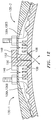
- a multiple of dilution holes 116 penetrate through both the respective support shells 68, 70 and heat shields 72, 74 along an axis that could be common or uncommon as indicated in Figure 5 .
- the dilution holes 116 are located downstream of the forward assembly 80 to quench the hot gases by supplying cooling air into the combustor.
- the hot combustion gases slow towards the dilution holes 116 and may form a stagnation point at the leading edge which becomes a heat source.
- hot gases form a standing vortex pair that may also become a heat source.
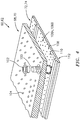
- FIG. 6 a lateral cross-section of the support shells 68, 70 and heat shields 72, 74 with their respective cavities 106A, 106B are illustrated with respect to the combustion chamber 66. Although only one of the support shells 68, 70 and heat shields 72, 74 is illustrated and described in detail hereafter, it should be understood that each of the support shells 68, 70 and heat shields 72, 74 are generally the same and need not be described in detail herein.
- each support shell 68, 70 defines a non-planar profile 122 such as a hyperbolic or catenary profile that faces an inner surface 124 of the heat shields 72, 74 within the respective cavities 106A, 106B.
- the inner surface 120 of each support shell 68, 70 defines a relatively thin cavity zone 126 along a central portion of each combustor section 128 with respect to the inner surface 124 of the heat shields 72, 74. That is, the relatively thin cavity zone 126 is defined generally parallel to the engine axis A and is flanked by relatively thicker cavity zones 128 of each combustor section 130 ( Figure 5 ).
- the convergent support shell 68, 70 profile may be the catenary profile is defined by a hyperbolic cosine function, cosh, which provides an approximate 4.5 inlet-to-exit area ratio.
- the inlet-to-exit area ratio forces a flow acceleration at an end of a circumferential convergent flow section.
- a corresponding increase in Reynolds number facilitates higher internal heat transfer coefficients for cooling.
- the relatively thicker cavity zones 128 receive airflow from the impingement holes 104.
- the airflow within the cavities 106A, 106B is from the relatively thicker cavity zones 128 toward the relatively thin cavity zone 126 to define the circumferential convergent flow section. That is, the airflow is generally in the circumferential direction rather than axial direction.
- the impingement holes 104 direct airflow onto a multiple of pin fins 132.
- the pin fins 132 in one example, may be diamond shaped pins that are approximately 1 ⁇ 2 - 3 ⁇ 4 the height between the inner surfaces 120, 124 in the relatively thicker cavity zones 128. It should be appreciated that other heights may be provided.
- a multiple of hemispherical nubbins 134 are located toward an exit splitter 136.
- the hemispherical nubbins 134 are of the same diameter but are progressively deeper into the inner surface 124. That is, centers of the respective spheres which in one disclosed non-limiting embodiment define the hemispherical nubbins 134 are progressively deeper into the combustion chamber 66.
- the hemispherical nubbins 134-1 are progressively smaller diameters toward the exit splitter 136 ( Figure 9 ).
- the hemispherical nubbins 134, 134-1 allow for less pressure resistance (less friction) that facilitates convergent flow channel acceleration capabilities.
- the hemispherical nubbins 134, 134-1 reduce the frictional drag resistance to the cooling flow yet augment cooling of the inner surface 124. It should be appreciated that the hemispherical nubbins 134, 134-1 may be arranged in various patterns.
- the exit splitter 136 is zigzag in shape along the axis A such that a film hole 108 may be located in a valley 138 on each side of the exit splitter 136. As defined herein "zigzag” includes, but is not limited to, any serpentine, saw tooth or non-straight wall.
- the exit splitter 136 also forms a base for a frustro-conical stud 100 (only one shown).
- the stud 100 is received within a corresponding aperture 140 in the heat shields 72, 74, such that as the nut 102 is tightened down on a threaded interface 142, the aperture 140 seals and tightens onto the frustro-conical stud portion 144 ( Figure 6 ).
- the threaded interface 144 also forces sets of interleaved cantilevered members 146, 148 along each edge 150, 152 of the heat shields 72, 74 to be forced together to facilitate a seal between each adjacent combustor section 130-1, 130-2 ( Figure 11 ).
- the frustro-conical studs 100 may alternatively or additionally located in other locations such as along the edges 150, 152.
- the interleaved cantilevered members 146, 148 react the force applied to the frustro-conical stud 100 to minimize leakage. It should be appreciated that the interleaved cantilevered members 146, 148 are of a J-shape.
- the film holes 108 along edge 150 of one combustor section 130-1 are directed toward edge 152 of the adjacent combustor section 130-2 and vice-versa.
- the cross-flow from the film holes 108 along edges 150, 152 protect the edges 150, 152 and further facilitate a seal between the interleaved cantilevered members 146, 148.
- the frustro-conical stud 100 and interleaved cantilevered members 146, 148 facilitate a relatively higher pressure within the cavities 106A, 106B.
- an equal number of impingement holes 104 and film holes 108 are located in each combustor section 130 to provide a approximately 50:50 pressure split as compared to a more conventional 80:20 pressure split with approximately half the number of impingement holes 104 compared to the film holes 108.
- the 50:50 pressure split permits a relatively higher pressure within the cavities 106A, 106B thereby permitting a relatively smaller number of holes and thereby a more efficient usage of air by spacing impingement holes 104 and film holes 108 further apart.
- Reduced reaction flame temperatures are also avoid local stoichiometric conditions and thereby reduce NOx formation
- the film holes 108 adjacent to the exit splitter 136 may be directed across an interface 154 between circumferentially distributed bulkhead heat shields 98. That is, the film holes 108 along one side of the exit splitter 136 are directed toward the opposite side and vice-versa. Such an arrangement may be advantageous when the fuel nozzle pre-swirlers 90 are axially displaced from the film holes 108.
- the film holes 108 on both sides of the zigzag exit splitter 136 through the heat shields 72, 74 are directed in a direction in coordination with the rotational direction of the fuel nozzle pre-swirlers 90.
- Such an arrangement may be advantageous when the fuel nozzle pre-swirlers 90 are positioned relatively close to the film holes 108. It should be appreciated that the rotational direction may be clockwise or counter-clockwise.
- the film holes 108 on both sides of the zigzag exit splitter 136 through the heat shields 72, 74 are directed in a direction in-line the rotational direction of the fuel nozzle pre-swirlers 90.
- the non-planar profile 122 may include pre-drilled apertures 156 located in potential hot spots. These apertunes 156 are not initially drilled completely through the support shell 68, 70. That is the pre-drilled apertures 156 are placed in the convergent section close to an area where hot-spots may occur. Should the hot-spot prediction be realized, then apertures 156 are drilled completely through the support shell 68, 70 to supply refresher air into the convergent section pre-drilled apertures 156. This will effectively address the hot-spot by maintaining the coolant heat pick-up low; while introducing more convective flow into the circuit. Furthermore, even if not drilled completely through, the pre-drilled apertures 156 provide weight reduction.
Landscapes
- Engineering & Computer Science (AREA)
- Chemical & Material Sciences (AREA)
- Combustion & Propulsion (AREA)
- Mechanical Engineering (AREA)
- General Engineering & Computer Science (AREA)
- Turbine Rotor Nozzle Sealing (AREA)
Claims (8)
- Chambre de combustion (56) d'une turbine à gaz (20) comprenant :un premier écran thermique (72) qui comprend un premier bord avec un premier ensemble d'éléments en porte-à-faux (146) ; etun second écran thermique (74) qui comprend un second bord, le second bord ayant un second ensemble d'éléments en porte-à-faux (148) entrelacés avec ledit premier ensemble d'éléments en porte-à-faux (146) ;dans laquelle ledit premier ensemble d'éléments en porte-à-faux (146) et ledit second ensemble d'éléments en porte-à-faux (148) sont des crochets en forme de J.
- Chambre de combustion selon la revendication 1, comprenant en outre un séparateur de sortie (136) qui s'étend depuis l'un dudit premier écran thermique (72) ou dudit second écran thermique (74), dans laquelle ledit séparateur de sortie (136) a une forme en zigzag et/ou comprend en outre un trou de film (108) situé dans un creux (138) de chaque côté dudit séparateur de sortie (136).
- Chambre de combustion selon la revendication 1 ou 2, comprenant en outre une pluralité de goujons (100) qui s'étendent depuis l'un dudit premier écran thermique (72) ou dudit second écran thermique (74), lesdits goujons (100) comprenant une section tronconique.
- Chambre de combustion selon une quelconque revendication précédente, dans laquelle l'un dudit premier écran thermique (72) ou dudit second écran thermique (74) comprend une pluralité d'ailettes à broches (132), dans laquelle ladite pluralité d'ailettes à broches (132) est en forme de diamant.
- Chambre de combustion selon une quelconque revendication précédente, dans laquelle l'un dudit premier écran thermique (72) ou dudit second écran thermique (74) comprend une multitude de protubérances (134), dans laquelle ladite multitude de protubérances (134) diminue en diamètre vers un ou ledit séparateur de sortie (136).
- Chambre de combustion selon l'une quelconque des revendications 1 à 4, dans laquelle l'un dudit premier écran thermique (72) ou dudit second écran thermique (74) comprend une multitude de protubérances (134), un centre d'une sphère définie par chacun de ladite multitude de protubérances (134) qui sont en outre déplacés d'une surface interne dudit écran thermique (72, 74) vers un ou ledit séparateur de sortie.
- Procédé de montage d'un ensemble revêtement d'une chambre de combustion pour une turbine à gaz, comprenant :
l'entrelacement d'un premier écran thermique (72) avec un second écran thermique (74) en entrelaçant un premier ensemble d'éléments en porte-à-faux (146) qui s'étendent depuis ledit premier écran thermique (72) avec un second ensemble d'éléments en porte-à-faux (48) qui s'étendent depuis ledit second écran thermique (74), dans lequel ledit premier ensemble d'éléments en porte-à-faux (146) et ledit second ensemble d'éléments en porte-à-faux (148) sont des crochets en forme de J. - Procédé selon la revendication 7, comprenant en outre :
le filetage d'un écrou (102) sur un goujon (100) qui s'étend depuis ledit premier écran thermique (72) pour entraîner une coque de support (68) sur ledit premier écran thermique (72).
Applications Claiming Priority (2)
| Application Number | Priority Date | Filing Date | Title |
|---|---|---|---|
| US201361762367P | 2013-02-08 | 2013-02-08 | |
| PCT/US2014/014819 WO2014189556A2 (fr) | 2013-02-08 | 2014-02-05 | Ensemble chemise de chambre de combustion de turbine à gaz avec profil hyperbolique convergent |
Publications (3)
| Publication Number | Publication Date |
|---|---|
| EP2954261A2 EP2954261A2 (fr) | 2015-12-16 |
| EP2954261A4 EP2954261A4 (fr) | 2016-07-06 |
| EP2954261B1 true EP2954261B1 (fr) | 2020-03-04 |
Family
ID=51934295
Family Applications (1)
| Application Number | Title | Priority Date | Filing Date |
|---|---|---|---|
| EP14801039.0A Active EP2954261B1 (fr) | 2013-02-08 | 2014-02-05 | Chambre de combustion de turbine à gaz |
Country Status (3)
| Country | Link |
|---|---|
| US (1) | US10174949B2 (fr) |
| EP (1) | EP2954261B1 (fr) |
| WO (1) | WO2014189556A2 (fr) |
Families Citing this family (13)
| Publication number | Priority date | Publication date | Assignee | Title |
|---|---|---|---|---|
| US10197285B2 (en) * | 2013-12-06 | 2019-02-05 | United Technologies Corporation | Gas turbine engine wall assembly interface |
| GB201322838D0 (en) * | 2013-12-23 | 2014-02-12 | Rolls Royce Plc | A combustion chamber |
| WO2015103357A1 (fr) * | 2013-12-31 | 2015-07-09 | United Technologies Corporation | Ensemble paroi de moteur à turbine à gaz à architecture d'écoulement améliorée |
| WO2015116360A1 (fr) * | 2014-01-30 | 2015-08-06 | United Technologies Corporation | Flux de refroidissement pour un panneau principal dans une chambre de combustion de moteur à turbine à gaz |
| US10533745B2 (en) * | 2014-02-03 | 2020-01-14 | United Technologies Corporation | Film cooling a combustor wall of a turbine engine |
| GB201501817D0 (en) * | 2015-02-04 | 2015-03-18 | Rolls Royce Plc | A combustion chamber and a combustion chamber segment |
| CA2925588A1 (fr) * | 2015-04-29 | 2016-10-29 | Rolls-Royce Corporation | Sillage de pale brase destine a une turbine a gaz |
| GB201518345D0 (en) * | 2015-10-16 | 2015-12-02 | Rolls Royce | Combustor for a gas turbine engine |
| US20180299126A1 (en) * | 2017-04-18 | 2018-10-18 | United Technologies Corporation | Combustor liner panel end rail |
| US20180306113A1 (en) * | 2017-04-19 | 2018-10-25 | United Technologies Corporation | Combustor liner panel end rail matching heat transfer features |
| US10473331B2 (en) | 2017-05-18 | 2019-11-12 | United Technologies Corporation | Combustor panel endrail interface |
| US11415320B2 (en) | 2019-01-04 | 2022-08-16 | Raytheon Technologies Corporation | Combustor cooling panel with flow guide |
| EP3848556A1 (fr) * | 2020-01-13 | 2021-07-14 | Ansaldo Energia Switzerland AG | Moteur à turbine à gaz ayant une pièce de transition avec trous de refroidissement obliques |
Family Cites Families (51)
| Publication number | Priority date | Publication date | Assignee | Title |
|---|---|---|---|---|
| US3986347A (en) | 1973-12-06 | 1976-10-19 | Phillips Petroleum Company | Combustor process for low-level NOx and CO emissions |
| US4012902A (en) | 1974-03-29 | 1977-03-22 | Phillips Petroleum Company | Method of operating a gas turbine combustor having an independent airstream to remove heat from the primary combustion zone |
| GB2044912B (en) | 1979-03-22 | 1983-02-23 | Rolls Royce | Gas turbine combustion chamber |
| US4242871A (en) | 1979-09-18 | 1981-01-06 | United Technologies Corporation | Louver burner liner |
| US4655044A (en) | 1983-12-21 | 1987-04-07 | United Technologies Corporation | Coated high temperature combustor liner |
| EP0204553B1 (fr) | 1985-06-07 | 1989-06-07 | Ruston Gas Turbines Limited | Chaudière de combustion pour une turbine à gaz |
| US4843825A (en) * | 1988-05-16 | 1989-07-04 | United Technologies Corporation | Combustor dome heat shield |
| FR2644209B1 (fr) * | 1989-03-08 | 1991-05-03 | Snecma | Chemise de protection thermique pour canal chaud de turboreacteur |
| US5233828A (en) | 1990-11-15 | 1993-08-10 | General Electric Company | Combustor liner with circumferentially angled film cooling holes |
| US5181379A (en) | 1990-11-15 | 1993-01-26 | General Electric Company | Gas turbine engine multi-hole film cooled combustor liner and method of manufacture |
| CA2056592A1 (fr) | 1990-12-21 | 1992-06-22 | Phillip D. Napoli | Chemise de chambre de combustion a refroidissement par gaine d'air a trous multiples avec demarreur a gaine d'air rainuree |
| US5169287A (en) | 1991-05-20 | 1992-12-08 | General Electric Company | Shroud cooling assembly for gas turbine engine |
| US5261223A (en) | 1992-10-07 | 1993-11-16 | General Electric Company | Multi-hole film cooled combustor liner with rectangular film restarting holes |
| US5271220A (en) | 1992-10-16 | 1993-12-21 | Sundstrand Corporation | Combustor heat shield for a turbine containment ring |
| US5323604A (en) | 1992-11-16 | 1994-06-28 | General Electric Company | Triple annular combustor for gas turbine engine |
| EP0788546B9 (fr) | 1994-10-18 | 2007-06-13 | Dendreon Corporation | Proteines anticoagulantes et inhibiteurs de la serine-protease extraits de nematodes |
| US5623827A (en) | 1995-01-26 | 1997-04-29 | General Electric Company | Regenerative cooled dome assembly for a gas turbine engine combustor |
| US5630319A (en) | 1995-05-12 | 1997-05-20 | General Electric Company | Dome assembly for a multiple annular combustor |
| US5619855A (en) | 1995-06-07 | 1997-04-15 | General Electric Company | High inlet mach combustor for gas turbine engine |
| US5657633A (en) | 1995-12-29 | 1997-08-19 | General Electric Company | Centerbody for a multiple annular combustor |
| CA2273221A1 (fr) | 1996-12-03 | 1998-06-11 | Elliott Energy Systems, Inc. | Systeme generant de l'electricite avec chambre de combustion annulaire |
| US6237344B1 (en) | 1998-07-20 | 2001-05-29 | General Electric Company | Dimpled impingement baffle |
| US6286298B1 (en) | 1998-12-18 | 2001-09-11 | General Electric Company | Apparatus and method for rich-quench-lean (RQL) concept in a gas turbine engine combustor having trapped vortex cavity |
| US6279323B1 (en) | 1999-11-01 | 2001-08-28 | General Electric Company | Low emissions combustor |
| US6374615B1 (en) | 2000-01-28 | 2002-04-23 | Alliedsignal, Inc | Low cost, low emissions natural gas combustor |
| US6540162B1 (en) | 2000-06-28 | 2003-04-01 | General Electric Company | Methods and apparatus for decreasing combustor emissions with spray bar assembly |
| US6655147B2 (en) | 2002-04-10 | 2003-12-02 | General Electric Company | Annular one-piece corrugated liner for combustor of a gas turbine engine |
| US7093439B2 (en) * | 2002-05-16 | 2006-08-22 | United Technologies Corporation | Heat shield panels for use in a combustor for a gas turbine engine |
| US6968693B2 (en) | 2003-09-22 | 2005-11-29 | General Electric Company | Method and apparatus for reducing gas turbine engine emissions |
| US7093441B2 (en) | 2003-10-09 | 2006-08-22 | United Technologies Corporation | Gas turbine annular combustor having a first converging volume and a second converging volume, converging less gradually than the first converging volume |
| US7363763B2 (en) | 2003-10-23 | 2008-04-29 | United Technologies Corporation | Combustor |
| US7296967B2 (en) | 2005-09-13 | 2007-11-20 | General Electric Company | Counterflow film cooled wall |
| US7954325B2 (en) | 2005-12-06 | 2011-06-07 | United Technologies Corporation | Gas turbine combustor |
| US7878000B2 (en) | 2005-12-20 | 2011-02-01 | General Electric Company | Pilot fuel injector for mixer assembly of a high pressure gas turbine engine |
| GB2434199B (en) | 2006-01-14 | 2011-01-05 | Alstom Technology Ltd | Combustor liner with heat shield |
| US7681398B2 (en) * | 2006-11-17 | 2010-03-23 | Pratt & Whitney Canada Corp. | Combustor liner and heat shield assembly |
| US7721548B2 (en) | 2006-11-17 | 2010-05-25 | Pratt & Whitney Canada Corp. | Combustor liner and heat shield assembly |
| US7748221B2 (en) | 2006-11-17 | 2010-07-06 | Pratt & Whitney Canada Corp. | Combustor heat shield with variable cooling |
| US7845174B2 (en) | 2007-04-19 | 2010-12-07 | Pratt & Whitney Canada Corp. | Combustor liner with improved heat shield retention |
| FR2918444B1 (fr) * | 2007-07-05 | 2013-06-28 | Snecma | Deflecteur de fond de chambre, chambre de combustion le comportant et moteur a turbine a gaz en etant equipe |
| US8266914B2 (en) | 2008-10-22 | 2012-09-18 | Pratt & Whitney Canada Corp. | Heat shield sealing for gas turbine engine combustor |
| US20100223931A1 (en) * | 2009-03-04 | 2010-09-09 | General Electric Company | Pattern cooled combustor liner |
| US8397511B2 (en) | 2009-05-19 | 2013-03-19 | General Electric Company | System and method for cooling a wall of a gas turbine combustor |
| DE102009032277A1 (de) | 2009-07-08 | 2011-01-20 | Rolls-Royce Deutschland Ltd & Co Kg | Brennkammerkopf einer Gasturbine |
| US9416970B2 (en) | 2009-11-30 | 2016-08-16 | United Technologies Corporation | Combustor heat panel arrangement having holes offset from seams of a radially opposing heat panel |
| US20130000309A1 (en) | 2011-06-30 | 2013-01-03 | United Technologies Corporation | System and method for adaptive impingement cooling |
| US9534783B2 (en) | 2011-07-21 | 2017-01-03 | United Technologies Corporation | Insert adjacent to a heat shield element for a gas turbine engine combustor |
| CH705514A1 (de) * | 2011-09-05 | 2013-03-15 | Alstom Technology Ltd | Gaskanal für eine Gasturbine sowie Gasturbine mit einem solchen Gaskanal. |
| EP2693121B1 (fr) * | 2012-07-31 | 2018-04-25 | Ansaldo Energia Switzerland AG | Rugosité proche de la paroi pour dispositifs d'amortissement réduisant les oscillations de pression dans les systèmes de combustion |
| US20150362192A1 (en) | 2013-01-17 | 2015-12-17 | United Technologies Corporation | Gas turbine engine combustor liner assembly with convergent hyperbolic profile |
| GB201322838D0 (en) * | 2013-12-23 | 2014-02-12 | Rolls Royce Plc | A combustion chamber |
-
2014
- 2014-02-05 US US14/765,227 patent/US10174949B2/en active Active
- 2014-02-05 WO PCT/US2014/014819 patent/WO2014189556A2/fr active Application Filing
- 2014-02-05 EP EP14801039.0A patent/EP2954261B1/fr active Active
Non-Patent Citations (1)
| Title |
|---|
| None * |
Also Published As
| Publication number | Publication date |
|---|---|
| US10174949B2 (en) | 2019-01-08 |
| WO2014189556A2 (fr) | 2014-11-27 |
| EP2954261A4 (fr) | 2016-07-06 |
| WO2014189556A3 (fr) | 2015-01-29 |
| EP2954261A2 (fr) | 2015-12-16 |
| US20150369490A1 (en) | 2015-12-24 |
Similar Documents
| Publication | Publication Date | Title |
|---|---|---|
| EP2946092B1 (fr) | Ensemble revêtement pour chambre de combustion de turbine à gaz équipé d'un profil hyperbolique convergent | |
| EP2954261B1 (fr) | Chambre de combustion de turbine à gaz | |
| EP3366995B1 (fr) | Assemblage de panneau de chambre de combustion et procédé pour son refroidissement | |
| EP2959136B1 (fr) | Chambre de combustion de moteur à turbine à gaz avec rondelle à aillettes pour allumeur | |
| EP2984317B1 (fr) | Refroidissement de jonction en t de panneau de chambre de combustion | |
| EP3077728B1 (fr) | Chambre de combustion de moteur à turbine à gaz ayant des passages d'effusion avec orientation de co-tourbillonnement, et procédé | |
| EP2932070B1 (fr) | Bouclier thermique de chambre de combustion de moteur à turbine à gaz avec efficacité de refroidissement pelliculaire accrue | |
| US9958160B2 (en) | Gas turbine engine component with upstream-directed cooling film holes | |
| US10823411B2 (en) | Combustor liner panel end rail cooling enhancement features for a gas turbine engine combustor | |
| US10830448B2 (en) | Combustor liner panel with a multiple of heat transfer augmentors for a gas turbine engine combustor | |
| EP2971668A2 (fr) | Refroidissement actif de bossages d'oeillet pour un panneau de chambre de combustion d'un moteur à turbine à gaz | |
| WO2015103357A1 (fr) | Ensemble paroi de moteur à turbine à gaz à architecture d'écoulement améliorée | |
| EP3315730A1 (fr) | Joint de chambre de combustion pour chambre de combustion de moteur de turbine à gaz | |
| US10830433B2 (en) | Axial non-linear interface for combustor liner panels in a gas turbine combustor | |
| EP3084307B1 (fr) | Agencement de passage d'apport d'air pour chambre de combustion de moteur à turbine à gaz |
Legal Events
| Date | Code | Title | Description |
|---|---|---|---|
| PUAI | Public reference made under article 153(3) epc to a published international application that has entered the european phase |
Free format text: ORIGINAL CODE: 0009012 |
|
| 17P | Request for examination filed |
Effective date: 20150904 |
|
| AK | Designated contracting states |
Kind code of ref document: A2 Designated state(s): AL AT BE BG CH CY CZ DE DK EE ES FI FR GB GR HR HU IE IS IT LI LT LU LV MC MK MT NL NO PL PT RO RS SE SI SK SM TR |
|
| AX | Request for extension of the european patent |
Extension state: BA ME |
|
| DAX | Request for extension of the european patent (deleted) | ||
| A4 | Supplementary search report drawn up and despatched |
Effective date: 20160603 |
|
| RIC1 | Information provided on ipc code assigned before grant |
Ipc: F02C 7/12 20060101ALI20160530BHEP Ipc: F23M 5/04 20060101AFI20160530BHEP Ipc: F23R 3/42 20060101ALI20160530BHEP Ipc: F23M 5/08 20060101ALI20160530BHEP |
|
| RAP1 | Party data changed (applicant data changed or rights of an application transferred) |
Owner name: UNITED TECHNOLOGIES CORPORATION |
|
| GRAP | Despatch of communication of intention to grant a patent |
Free format text: ORIGINAL CODE: EPIDOSNIGR1 |
|
| STAA | Information on the status of an ep patent application or granted ep patent |
Free format text: STATUS: GRANT OF PATENT IS INTENDED |
|
| INTG | Intention to grant announced |
Effective date: 20190326 |
|
| GRAS | Grant fee paid |
Free format text: ORIGINAL CODE: EPIDOSNIGR3 |
|
| GRAA | (expected) grant |
Free format text: ORIGINAL CODE: 0009210 |
|
| STAA | Information on the status of an ep patent application or granted ep patent |
Free format text: STATUS: THE PATENT HAS BEEN GRANTED |
|
| AK | Designated contracting states |
Kind code of ref document: B1 Designated state(s): AL AT BE BG CH CY CZ DE DK EE ES FI FR GB GR HR HU IE IS IT LI LT LU LV MC MK MT NL NO PL PT RO RS SE SI SK SM TR |
|
| REG | Reference to a national code |
Ref country code: GB Ref legal event code: FG4D |
|
| REG | Reference to a national code |
Ref country code: CH Ref legal event code: EP |
|
| REG | Reference to a national code |
Ref country code: AT Ref legal event code: REF Ref document number: 1240803 Country of ref document: AT Kind code of ref document: T Effective date: 20200315 |
|
| REG | Reference to a national code |
Ref country code: DE Ref legal event code: R096 Ref document number: 602014061927 Country of ref document: DE |
|
| REG | Reference to a national code |
Ref country code: IE Ref legal event code: FG4D |
|
| PG25 | Lapsed in a contracting state [announced via postgrant information from national office to epo] |
Ref country code: RS Free format text: LAPSE BECAUSE OF FAILURE TO SUBMIT A TRANSLATION OF THE DESCRIPTION OR TO PAY THE FEE WITHIN THE PRESCRIBED TIME-LIMIT Effective date: 20200304 Ref country code: NO Free format text: LAPSE BECAUSE OF FAILURE TO SUBMIT A TRANSLATION OF THE DESCRIPTION OR TO PAY THE FEE WITHIN THE PRESCRIBED TIME-LIMIT Effective date: 20200604 Ref country code: FI Free format text: LAPSE BECAUSE OF FAILURE TO SUBMIT A TRANSLATION OF THE DESCRIPTION OR TO PAY THE FEE WITHIN THE PRESCRIBED TIME-LIMIT Effective date: 20200304 |
|
| REG | Reference to a national code |
Ref country code: NL Ref legal event code: MP Effective date: 20200304 |
|
| PG25 | Lapsed in a contracting state [announced via postgrant information from national office to epo] |
Ref country code: GR Free format text: LAPSE BECAUSE OF FAILURE TO SUBMIT A TRANSLATION OF THE DESCRIPTION OR TO PAY THE FEE WITHIN THE PRESCRIBED TIME-LIMIT Effective date: 20200605 Ref country code: BG Free format text: LAPSE BECAUSE OF FAILURE TO SUBMIT A TRANSLATION OF THE DESCRIPTION OR TO PAY THE FEE WITHIN THE PRESCRIBED TIME-LIMIT Effective date: 20200604 Ref country code: SE Free format text: LAPSE BECAUSE OF FAILURE TO SUBMIT A TRANSLATION OF THE DESCRIPTION OR TO PAY THE FEE WITHIN THE PRESCRIBED TIME-LIMIT Effective date: 20200304 Ref country code: LV Free format text: LAPSE BECAUSE OF FAILURE TO SUBMIT A TRANSLATION OF THE DESCRIPTION OR TO PAY THE FEE WITHIN THE PRESCRIBED TIME-LIMIT Effective date: 20200304 Ref country code: HR Free format text: LAPSE BECAUSE OF FAILURE TO SUBMIT A TRANSLATION OF THE DESCRIPTION OR TO PAY THE FEE WITHIN THE PRESCRIBED TIME-LIMIT Effective date: 20200304 |
|
| REG | Reference to a national code |
Ref country code: LT Ref legal event code: MG4D |
|
| PG25 | Lapsed in a contracting state [announced via postgrant information from national office to epo] |
Ref country code: NL Free format text: LAPSE BECAUSE OF FAILURE TO SUBMIT A TRANSLATION OF THE DESCRIPTION OR TO PAY THE FEE WITHIN THE PRESCRIBED TIME-LIMIT Effective date: 20200304 |
|
| PG25 | Lapsed in a contracting state [announced via postgrant information from national office to epo] |
Ref country code: CZ Free format text: LAPSE BECAUSE OF FAILURE TO SUBMIT A TRANSLATION OF THE DESCRIPTION OR TO PAY THE FEE WITHIN THE PRESCRIBED TIME-LIMIT Effective date: 20200304 Ref country code: RO Free format text: LAPSE BECAUSE OF FAILURE TO SUBMIT A TRANSLATION OF THE DESCRIPTION OR TO PAY THE FEE WITHIN THE PRESCRIBED TIME-LIMIT Effective date: 20200304 Ref country code: PT Free format text: LAPSE BECAUSE OF FAILURE TO SUBMIT A TRANSLATION OF THE DESCRIPTION OR TO PAY THE FEE WITHIN THE PRESCRIBED TIME-LIMIT Effective date: 20200729 Ref country code: ES Free format text: LAPSE BECAUSE OF FAILURE TO SUBMIT A TRANSLATION OF THE DESCRIPTION OR TO PAY THE FEE WITHIN THE PRESCRIBED TIME-LIMIT Effective date: 20200304 Ref country code: SM Free format text: LAPSE BECAUSE OF FAILURE TO SUBMIT A TRANSLATION OF THE DESCRIPTION OR TO PAY THE FEE WITHIN THE PRESCRIBED TIME-LIMIT Effective date: 20200304 Ref country code: EE Free format text: LAPSE BECAUSE OF FAILURE TO SUBMIT A TRANSLATION OF THE DESCRIPTION OR TO PAY THE FEE WITHIN THE PRESCRIBED TIME-LIMIT Effective date: 20200304 Ref country code: LT Free format text: LAPSE BECAUSE OF FAILURE TO SUBMIT A TRANSLATION OF THE DESCRIPTION OR TO PAY THE FEE WITHIN THE PRESCRIBED TIME-LIMIT Effective date: 20200304 Ref country code: IS Free format text: LAPSE BECAUSE OF FAILURE TO SUBMIT A TRANSLATION OF THE DESCRIPTION OR TO PAY THE FEE WITHIN THE PRESCRIBED TIME-LIMIT Effective date: 20200704 Ref country code: SK Free format text: LAPSE BECAUSE OF FAILURE TO SUBMIT A TRANSLATION OF THE DESCRIPTION OR TO PAY THE FEE WITHIN THE PRESCRIBED TIME-LIMIT Effective date: 20200304 |
|
| REG | Reference to a national code |
Ref country code: AT Ref legal event code: MK05 Ref document number: 1240803 Country of ref document: AT Kind code of ref document: T Effective date: 20200304 |
|
| REG | Reference to a national code |
Ref country code: DE Ref legal event code: R097 Ref document number: 602014061927 Country of ref document: DE |
|
| PLBE | No opposition filed within time limit |
Free format text: ORIGINAL CODE: 0009261 |
|
| STAA | Information on the status of an ep patent application or granted ep patent |
Free format text: STATUS: NO OPPOSITION FILED WITHIN TIME LIMIT |
|
| PG25 | Lapsed in a contracting state [announced via postgrant information from national office to epo] |
Ref country code: IT Free format text: LAPSE BECAUSE OF FAILURE TO SUBMIT A TRANSLATION OF THE DESCRIPTION OR TO PAY THE FEE WITHIN THE PRESCRIBED TIME-LIMIT Effective date: 20200304 Ref country code: AT Free format text: LAPSE BECAUSE OF FAILURE TO SUBMIT A TRANSLATION OF THE DESCRIPTION OR TO PAY THE FEE WITHIN THE PRESCRIBED TIME-LIMIT Effective date: 20200304 Ref country code: DK Free format text: LAPSE BECAUSE OF FAILURE TO SUBMIT A TRANSLATION OF THE DESCRIPTION OR TO PAY THE FEE WITHIN THE PRESCRIBED TIME-LIMIT Effective date: 20200304 |
|
| 26N | No opposition filed |
Effective date: 20201207 |
|
| PG25 | Lapsed in a contracting state [announced via postgrant information from national office to epo] |
Ref country code: PL Free format text: LAPSE BECAUSE OF FAILURE TO SUBMIT A TRANSLATION OF THE DESCRIPTION OR TO PAY THE FEE WITHIN THE PRESCRIBED TIME-LIMIT Effective date: 20200304 Ref country code: SI Free format text: LAPSE BECAUSE OF FAILURE TO SUBMIT A TRANSLATION OF THE DESCRIPTION OR TO PAY THE FEE WITHIN THE PRESCRIBED TIME-LIMIT Effective date: 20200304 |
|
| PG25 | Lapsed in a contracting state [announced via postgrant information from national office to epo] |
Ref country code: MC Free format text: LAPSE BECAUSE OF FAILURE TO SUBMIT A TRANSLATION OF THE DESCRIPTION OR TO PAY THE FEE WITHIN THE PRESCRIBED TIME-LIMIT Effective date: 20200304 |
|
| REG | Reference to a national code |
Ref country code: BE Ref legal event code: MM Effective date: 20210228 |
|
| PG25 | Lapsed in a contracting state [announced via postgrant information from national office to epo] |
Ref country code: CH Free format text: LAPSE BECAUSE OF NON-PAYMENT OF DUE FEES Effective date: 20210228 Ref country code: LU Free format text: LAPSE BECAUSE OF NON-PAYMENT OF DUE FEES Effective date: 20210205 Ref country code: LI Free format text: LAPSE BECAUSE OF NON-PAYMENT OF DUE FEES Effective date: 20210228 |
|
| PG25 | Lapsed in a contracting state [announced via postgrant information from national office to epo] |
Ref country code: IE Free format text: LAPSE BECAUSE OF NON-PAYMENT OF DUE FEES Effective date: 20210205 |
|
| PG25 | Lapsed in a contracting state [announced via postgrant information from national office to epo] |
Ref country code: BE Free format text: LAPSE BECAUSE OF NON-PAYMENT OF DUE FEES Effective date: 20210228 |
|
| REG | Reference to a national code |
Ref country code: DE Ref legal event code: R081 Ref document number: 602014061927 Country of ref document: DE Owner name: RAYTHEON TECHNOLOGIES CORPORATION (N.D.GES.D.S, US Free format text: FORMER OWNER: UNITED TECHNOLOGIES CORPORATION, FARMINGTON, CONN., US |
|
| PG25 | Lapsed in a contracting state [announced via postgrant information from national office to epo] |
Ref country code: HU Free format text: LAPSE BECAUSE OF FAILURE TO SUBMIT A TRANSLATION OF THE DESCRIPTION OR TO PAY THE FEE WITHIN THE PRESCRIBED TIME-LIMIT; INVALID AB INITIO Effective date: 20140205 |
|
| P01 | Opt-out of the competence of the unified patent court (upc) registered |
Effective date: 20230520 |
|
| PG25 | Lapsed in a contracting state [announced via postgrant information from national office to epo] |
Ref country code: CY Free format text: LAPSE BECAUSE OF FAILURE TO SUBMIT A TRANSLATION OF THE DESCRIPTION OR TO PAY THE FEE WITHIN THE PRESCRIBED TIME-LIMIT Effective date: 20200304 |
|
| PG25 | Lapsed in a contracting state [announced via postgrant information from national office to epo] |
Ref country code: MK Free format text: LAPSE BECAUSE OF FAILURE TO SUBMIT A TRANSLATION OF THE DESCRIPTION OR TO PAY THE FEE WITHIN THE PRESCRIBED TIME-LIMIT Effective date: 20200304 |
|
| PGFP | Annual fee paid to national office [announced via postgrant information from national office to epo] |
Ref country code: DE Payment date: 20240123 Year of fee payment: 11 Ref country code: GB Payment date: 20240123 Year of fee payment: 11 |
|
| PGFP | Annual fee paid to national office [announced via postgrant information from national office to epo] |
Ref country code: FR Payment date: 20240123 Year of fee payment: 11 |
|
| PG25 | Lapsed in a contracting state [announced via postgrant information from national office to epo] |
Ref country code: TR Free format text: LAPSE BECAUSE OF FAILURE TO SUBMIT A TRANSLATION OF THE DESCRIPTION OR TO PAY THE FEE WITHIN THE PRESCRIBED TIME-LIMIT Effective date: 20200304 |
|
| PG25 | Lapsed in a contracting state [announced via postgrant information from national office to epo] |
Ref country code: MT Free format text: LAPSE BECAUSE OF FAILURE TO SUBMIT A TRANSLATION OF THE DESCRIPTION OR TO PAY THE FEE WITHIN THE PRESCRIBED TIME-LIMIT Effective date: 20200304 |