EP3102389B1 - System zur additiven fertigung mit mehrlaserstrahlpistole und verfahren zum betrieb - Google Patents
System zur additiven fertigung mit mehrlaserstrahlpistole und verfahren zum betrieb Download PDFInfo
- Publication number
- EP3102389B1 EP3102389B1 EP15745849.8A EP15745849A EP3102389B1 EP 3102389 B1 EP3102389 B1 EP 3102389B1 EP 15745849 A EP15745849 A EP 15745849A EP 3102389 B1 EP3102389 B1 EP 3102389B1
- Authority
- EP
- European Patent Office
- Prior art keywords
- energy
- lasers
- substrate
- combinator
- housing
- Prior art date
- Legal status (The legal status is an assumption and is not a legal conclusion. Google has not performed a legal analysis and makes no representation as to the accuracy of the status listed.)
- Active
Links
- 238000004519 manufacturing process Methods 0.000 title claims description 25
- 239000000654 additive Substances 0.000 title claims description 20
- 230000000996 additive effect Effects 0.000 title claims description 20
- 238000000034 method Methods 0.000 title claims description 9
- 239000000843 powder Substances 0.000 claims description 31
- 239000000758 substrate Substances 0.000 claims description 17
- 238000002844 melting Methods 0.000 claims description 12
- 230000008018 melting Effects 0.000 claims description 12
- 239000000835 fiber Substances 0.000 claims description 10
- 239000000155 melt Substances 0.000 claims description 10
- 238000010438 heat treatment Methods 0.000 claims description 9
- 238000007711 solidification Methods 0.000 claims description 7
- 230000008023 solidification Effects 0.000 claims description 7
- 230000003750 conditioning effect Effects 0.000 claims description 2
- 239000010410 layer Substances 0.000 description 24
- 238000011960 computer-aided design Methods 0.000 description 5
- 230000001419 dependent effect Effects 0.000 description 3
- 239000000203 mixture Substances 0.000 description 3
- 239000000956 alloy Substances 0.000 description 2
- 229910045601 alloy Inorganic materials 0.000 description 2
- 238000010894 electron beam technology Methods 0.000 description 2
- 238000005516 engineering process Methods 0.000 description 2
- 239000002184 metal Substances 0.000 description 2
- 239000002245 particle Substances 0.000 description 2
- 238000010521 absorption reaction Methods 0.000 description 1
- 238000000149 argon plasma sintering Methods 0.000 description 1
- 230000015572 biosynthetic process Effects 0.000 description 1
- 239000000919 ceramic Substances 0.000 description 1
- 239000002131 composite material Substances 0.000 description 1
- 238000010276 construction Methods 0.000 description 1
- 238000001816 cooling Methods 0.000 description 1
- 239000013078 crystal Substances 0.000 description 1
- 230000005484 gravity Effects 0.000 description 1
- 230000003116 impacting effect Effects 0.000 description 1
- 230000003287 optical effect Effects 0.000 description 1
- 229920000642 polymer Polymers 0.000 description 1
- 239000002243 precursor Substances 0.000 description 1
- 238000002360 preparation method Methods 0.000 description 1
- 238000007712 rapid solidification Methods 0.000 description 1
- 239000002356 single layer Substances 0.000 description 1
- 238000003892 spreading Methods 0.000 description 1
Images


Classifications
-
- B—PERFORMING OPERATIONS; TRANSPORTING
- B22—CASTING; POWDER METALLURGY
- B22F—WORKING METALLIC POWDER; MANUFACTURE OF ARTICLES FROM METALLIC POWDER; MAKING METALLIC POWDER; APPARATUS OR DEVICES SPECIALLY ADAPTED FOR METALLIC POWDER
- B22F10/00—Additive manufacturing of workpieces or articles from metallic powder
- B22F10/20—Direct sintering or melting
- B22F10/28—Powder bed fusion, e.g. selective laser melting [SLM] or electron beam melting [EBM]
-
- B—PERFORMING OPERATIONS; TRANSPORTING
- B22—CASTING; POWDER METALLURGY
- B22F—WORKING METALLIC POWDER; MANUFACTURE OF ARTICLES FROM METALLIC POWDER; MAKING METALLIC POWDER; APPARATUS OR DEVICES SPECIALLY ADAPTED FOR METALLIC POWDER
- B22F10/00—Additive manufacturing of workpieces or articles from metallic powder
- B22F10/30—Process control
- B22F10/36—Process control of energy beam parameters
- B22F10/362—Process control of energy beam parameters for preheating
-
- B—PERFORMING OPERATIONS; TRANSPORTING
- B22—CASTING; POWDER METALLURGY
- B22F—WORKING METALLIC POWDER; MANUFACTURE OF ARTICLES FROM METALLIC POWDER; MAKING METALLIC POWDER; APPARATUS OR DEVICES SPECIALLY ADAPTED FOR METALLIC POWDER
- B22F10/00—Additive manufacturing of workpieces or articles from metallic powder
- B22F10/30—Process control
- B22F10/36—Process control of energy beam parameters
- B22F10/364—Process control of energy beam parameters for post-heating, e.g. remelting
-
- B—PERFORMING OPERATIONS; TRANSPORTING
- B22—CASTING; POWDER METALLURGY
- B22F—WORKING METALLIC POWDER; MANUFACTURE OF ARTICLES FROM METALLIC POWDER; MAKING METALLIC POWDER; APPARATUS OR DEVICES SPECIALLY ADAPTED FOR METALLIC POWDER
- B22F12/00—Apparatus or devices specially adapted for additive manufacturing; Auxiliary means for additive manufacturing; Combinations of additive manufacturing apparatus or devices with other processing apparatus or devices
- B22F12/38—Housings, e.g. machine housings
-
- B—PERFORMING OPERATIONS; TRANSPORTING
- B22—CASTING; POWDER METALLURGY
- B22F—WORKING METALLIC POWDER; MANUFACTURE OF ARTICLES FROM METALLIC POWDER; MAKING METALLIC POWDER; APPARATUS OR DEVICES SPECIALLY ADAPTED FOR METALLIC POWDER
- B22F12/00—Apparatus or devices specially adapted for additive manufacturing; Auxiliary means for additive manufacturing; Combinations of additive manufacturing apparatus or devices with other processing apparatus or devices
- B22F12/40—Radiation means
- B22F12/44—Radiation means characterised by the configuration of the radiation means
- B22F12/45—Two or more
-
- B—PERFORMING OPERATIONS; TRANSPORTING
- B22—CASTING; POWDER METALLURGY
- B22F—WORKING METALLIC POWDER; MANUFACTURE OF ARTICLES FROM METALLIC POWDER; MAKING METALLIC POWDER; APPARATUS OR DEVICES SPECIALLY ADAPTED FOR METALLIC POWDER
- B22F12/00—Apparatus or devices specially adapted for additive manufacturing; Auxiliary means for additive manufacturing; Combinations of additive manufacturing apparatus or devices with other processing apparatus or devices
- B22F12/40—Radiation means
- B22F12/46—Radiation means with translatory movement
- B22F12/47—Radiation means with translatory movement parallel to the deposition plane
-
- B—PERFORMING OPERATIONS; TRANSPORTING
- B22—CASTING; POWDER METALLURGY
- B22F—WORKING METALLIC POWDER; MANUFACTURE OF ARTICLES FROM METALLIC POWDER; MAKING METALLIC POWDER; APPARATUS OR DEVICES SPECIALLY ADAPTED FOR METALLIC POWDER
- B22F3/00—Manufacture of workpieces or articles from metallic powder characterised by the manner of compacting or sintering; Apparatus specially adapted therefor ; Presses and furnaces
- B22F3/10—Sintering only
- B22F3/105—Sintering only by using electric current other than for infrared radiant energy, laser radiation or plasma ; by ultrasonic bonding
-
- B—PERFORMING OPERATIONS; TRANSPORTING
- B23—MACHINE TOOLS; METAL-WORKING NOT OTHERWISE PROVIDED FOR
- B23K—SOLDERING OR UNSOLDERING; WELDING; CLADDING OR PLATING BY SOLDERING OR WELDING; CUTTING BY APPLYING HEAT LOCALLY, e.g. FLAME CUTTING; WORKING BY LASER BEAM
- B23K26/00—Working by laser beam, e.g. welding, cutting or boring
- B23K26/02—Positioning or observing the workpiece, e.g. with respect to the point of impact; Aligning, aiming or focusing the laser beam
- B23K26/06—Shaping the laser beam, e.g. by masks or multi-focusing
- B23K26/0604—Shaping the laser beam, e.g. by masks or multi-focusing by a combination of beams
- B23K26/0608—Shaping the laser beam, e.g. by masks or multi-focusing by a combination of beams in the same heat affected zone [HAZ]
-
- B—PERFORMING OPERATIONS; TRANSPORTING
- B23—MACHINE TOOLS; METAL-WORKING NOT OTHERWISE PROVIDED FOR
- B23K—SOLDERING OR UNSOLDERING; WELDING; CLADDING OR PLATING BY SOLDERING OR WELDING; CUTTING BY APPLYING HEAT LOCALLY, e.g. FLAME CUTTING; WORKING BY LASER BEAM
- B23K26/00—Working by laser beam, e.g. welding, cutting or boring
- B23K26/02—Positioning or observing the workpiece, e.g. with respect to the point of impact; Aligning, aiming or focusing the laser beam
- B23K26/06—Shaping the laser beam, e.g. by masks or multi-focusing
- B23K26/064—Shaping the laser beam, e.g. by masks or multi-focusing by means of optical elements, e.g. lenses, mirrors or prisms
- B23K26/0648—Shaping the laser beam, e.g. by masks or multi-focusing by means of optical elements, e.g. lenses, mirrors or prisms comprising lenses
-
- B—PERFORMING OPERATIONS; TRANSPORTING
- B23—MACHINE TOOLS; METAL-WORKING NOT OTHERWISE PROVIDED FOR
- B23K—SOLDERING OR UNSOLDERING; WELDING; CLADDING OR PLATING BY SOLDERING OR WELDING; CUTTING BY APPLYING HEAT LOCALLY, e.g. FLAME CUTTING; WORKING BY LASER BEAM
- B23K26/00—Working by laser beam, e.g. welding, cutting or boring
- B23K26/02—Positioning or observing the workpiece, e.g. with respect to the point of impact; Aligning, aiming or focusing the laser beam
- B23K26/06—Shaping the laser beam, e.g. by masks or multi-focusing
- B23K26/0665—Shaping the laser beam, e.g. by masks or multi-focusing by beam condensation on the workpiece, e.g. for focusing
-
- B—PERFORMING OPERATIONS; TRANSPORTING
- B23—MACHINE TOOLS; METAL-WORKING NOT OTHERWISE PROVIDED FOR
- B23K—SOLDERING OR UNSOLDERING; WELDING; CLADDING OR PLATING BY SOLDERING OR WELDING; CUTTING BY APPLYING HEAT LOCALLY, e.g. FLAME CUTTING; WORKING BY LASER BEAM
- B23K26/00—Working by laser beam, e.g. welding, cutting or boring
- B23K26/08—Devices involving relative movement between laser beam and workpiece
- B23K26/0869—Devices involving movement of the laser head in at least one axial direction
- B23K26/0876—Devices involving movement of the laser head in at least one axial direction in at least two axial directions
-
- B—PERFORMING OPERATIONS; TRANSPORTING
- B23—MACHINE TOOLS; METAL-WORKING NOT OTHERWISE PROVIDED FOR
- B23K—SOLDERING OR UNSOLDERING; WELDING; CLADDING OR PLATING BY SOLDERING OR WELDING; CUTTING BY APPLYING HEAT LOCALLY, e.g. FLAME CUTTING; WORKING BY LASER BEAM
- B23K26/00—Working by laser beam, e.g. welding, cutting or boring
- B23K26/34—Laser welding for purposes other than joining
- B23K26/342—Build-up welding
-
- B—PERFORMING OPERATIONS; TRANSPORTING
- B29—WORKING OF PLASTICS; WORKING OF SUBSTANCES IN A PLASTIC STATE IN GENERAL
- B29C—SHAPING OR JOINING OF PLASTICS; SHAPING OF MATERIAL IN A PLASTIC STATE, NOT OTHERWISE PROVIDED FOR; AFTER-TREATMENT OF THE SHAPED PRODUCTS, e.g. REPAIRING
- B29C64/00—Additive manufacturing, i.e. manufacturing of three-dimensional [3D] objects by additive deposition, additive agglomeration or additive layering, e.g. by 3D printing, stereolithography or selective laser sintering
- B29C64/10—Processes of additive manufacturing
- B29C64/141—Processes of additive manufacturing using only solid materials
- B29C64/153—Processes of additive manufacturing using only solid materials using layers of powder being selectively joined, e.g. by selective laser sintering or melting
-
- B—PERFORMING OPERATIONS; TRANSPORTING
- B29—WORKING OF PLASTICS; WORKING OF SUBSTANCES IN A PLASTIC STATE IN GENERAL
- B29C—SHAPING OR JOINING OF PLASTICS; SHAPING OF MATERIAL IN A PLASTIC STATE, NOT OTHERWISE PROVIDED FOR; AFTER-TREATMENT OF THE SHAPED PRODUCTS, e.g. REPAIRING
- B29C64/00—Additive manufacturing, i.e. manufacturing of three-dimensional [3D] objects by additive deposition, additive agglomeration or additive layering, e.g. by 3D printing, stereolithography or selective laser sintering
- B29C64/20—Apparatus for additive manufacturing; Details thereof or accessories therefor
- B29C64/264—Arrangements for irradiation
- B29C64/268—Arrangements for irradiation using laser beams; using electron beams [EB]
-
- B—PERFORMING OPERATIONS; TRANSPORTING
- B33—ADDITIVE MANUFACTURING TECHNOLOGY
- B33Y—ADDITIVE MANUFACTURING, i.e. MANUFACTURING OF THREE-DIMENSIONAL [3-D] OBJECTS BY ADDITIVE DEPOSITION, ADDITIVE AGGLOMERATION OR ADDITIVE LAYERING, e.g. BY 3-D PRINTING, STEREOLITHOGRAPHY OR SELECTIVE LASER SINTERING
- B33Y10/00—Processes of additive manufacturing
-
- B—PERFORMING OPERATIONS; TRANSPORTING
- B33—ADDITIVE MANUFACTURING TECHNOLOGY
- B33Y—ADDITIVE MANUFACTURING, i.e. MANUFACTURING OF THREE-DIMENSIONAL [3-D] OBJECTS BY ADDITIVE DEPOSITION, ADDITIVE AGGLOMERATION OR ADDITIVE LAYERING, e.g. BY 3-D PRINTING, STEREOLITHOGRAPHY OR SELECTIVE LASER SINTERING
- B33Y30/00—Apparatus for additive manufacturing; Details thereof or accessories therefor
-
- C—CHEMISTRY; METALLURGY
- C21—METALLURGY OF IRON
- C21D—MODIFYING THE PHYSICAL STRUCTURE OF FERROUS METALS; GENERAL DEVICES FOR HEAT TREATMENT OF FERROUS OR NON-FERROUS METALS OR ALLOYS; MAKING METAL MALLEABLE, e.g. BY DECARBURISATION OR TEMPERING
- C21D10/00—Modifying the physical properties by methods other than heat treatment or deformation
-
- C—CHEMISTRY; METALLURGY
- C22—METALLURGY; FERROUS OR NON-FERROUS ALLOYS; TREATMENT OF ALLOYS OR NON-FERROUS METALS
- C22F—CHANGING THE PHYSICAL STRUCTURE OF NON-FERROUS METALS AND NON-FERROUS ALLOYS
- C22F3/00—Changing the physical structure of non-ferrous metals or alloys by special physical methods, e.g. treatment with neutrons
- C22F3/02—Changing the physical structure of non-ferrous metals or alloys by special physical methods, e.g. treatment with neutrons by solidifying a melt controlled by supersonic waves or electric or magnetic fields
-
- B—PERFORMING OPERATIONS; TRANSPORTING
- B22—CASTING; POWDER METALLURGY
- B22F—WORKING METALLIC POWDER; MANUFACTURE OF ARTICLES FROM METALLIC POWDER; MAKING METALLIC POWDER; APPARATUS OR DEVICES SPECIALLY ADAPTED FOR METALLIC POWDER
- B22F10/00—Additive manufacturing of workpieces or articles from metallic powder
- B22F10/50—Treatment of workpieces or articles during build-up, e.g. treatments applied to fused layers during build-up
-
- Y—GENERAL TAGGING OF NEW TECHNOLOGICAL DEVELOPMENTS; GENERAL TAGGING OF CROSS-SECTIONAL TECHNOLOGIES SPANNING OVER SEVERAL SECTIONS OF THE IPC; TECHNICAL SUBJECTS COVERED BY FORMER USPC CROSS-REFERENCE ART COLLECTIONS [XRACs] AND DIGESTS
- Y02—TECHNOLOGIES OR APPLICATIONS FOR MITIGATION OR ADAPTATION AGAINST CLIMATE CHANGE
- Y02P—CLIMATE CHANGE MITIGATION TECHNOLOGIES IN THE PRODUCTION OR PROCESSING OF GOODS
- Y02P10/00—Technologies related to metal processing
- Y02P10/25—Process efficiency
Definitions
- the present disclosure relates to an additive manufacturing system and, more particularly, to an additive manufacturing system with a multi-laser beam gun and a method of operation.
- additive manufacturing systems include, for example, Additive Layer Manufacturing (ALM) Systems, such as Direct Metal Laser Sintering (DMLS), Selective Laser Melting (SLM), Laser Beam Melting (LBM) and Electron Beam Melting (EBM) that provide for the fabrication of complex metal, alloy, polymer, ceramic and composite structures by the freeform construction of the workpiece, layer-by-layer.
- ALM Additive Layer Manufacturing
- DMLS Direct Metal Laser Sintering
- SLM Selective Laser Melting
- LBM Laser Beam Melting
- EBM Electron Beam Melting
- the powder bed is spread over the completed solidified layer and the process repeats as part of the layer-by-layer fabrication of the workpiece.
- CAD Computer Aided Design
- the EBM System utilizes a single electron beam gun and the DMLS, SLM, and LBM Systems utilize a single laser as the energy source. Both system beam types are focused by a lens, then deflected by an electromagnetic scanner or rotating mirror so that the energy beam selectively impinges on the powder bed.
- the EBM System uses a beam of electrons accelerated by an electric potential difference and focused using electromagnetic lenses that selectively scan the powder bed.
- An additive manufacturing system for producing a workpiece from a substrate is claimed in claim 1.
- a method of additively manufacturing a workpiece according to another aspect of the present invention is claimed in claim 9.
- the method includes the step of pre-heating a region of the substrate with the second energy beam before melting the region into the melt pool by the first energy beam.
- FIG. 1 schematically illustrates an additive manufacturing system 20 according to one illustrative example of the present disclosure that may have a build table 22 for holding a powder bed 24, a particle spreader or wiper 26 for spreading the powder bed 24 over the build table, an energy gun 28 for selectively melting regions of a layer of the powder bed, a powder supply hopper 30 for supplying powder to the spreader 26, and a powder surplus hopper 32.
- the additive manufacturing system 20 may be constructed to build a workpiece 36 in a layer-by-layer fashion.
- a controller 38 may have an integral CAD system for modeling the workpiece 36 into a plurality of slices 40 additively built atop one-another generally in a vertical or z-coordinate direction (see arrow 42). Once manufactured, each solidified slice 40 corresponds to a layer 44 of the powder bed 24 prior to solidification. The layer 44 is placed on top of a build surface 46 of the previously solidified slice 40.
- the controller 38 generally operates the entire system through a series of electrical and/or digital signals 48 sent to the system 20 components. For instance, the controller 38 may send a signal 48 to a mechanical piston 50 of the supply hopper 30 to sequentially push a supply powder 52 upward for receipt by the spreader 26, or alternatively or in addition thereto, the supply hopper 30 may feed powder downward via gravity.
- the spreader 26 may be a wiper, roller or other device that pushes (see arrow 54) or otherwise places the supply powder 52 over the build surface 46 of the workpiece 36 by a pre-determined thickness established through downward movement (see arrow 42) of the build table 22 controlled by the controller 38. Any excess powder 56 may be pushed into the surplus hopper 32 by the spreader 26. It is further contemplated and understood that the layer 44 may not be composed of a powder but may take the form of any substrate that may be layed or applied across the build surface 46 in preparation for melting.
- the controller 38 may send a signal 48 to the energy gun 28 to activate and generally move along the top layer 44 at a controlled velocity and direction (see arrow 58) and thereby selectively melt the top layer 44 on a region-by-region basis into melt pools.
- the energy gun 28 may have a housing 60, a primary energy source device 62 for emitting a primary energy beam 64, a secondary energy device 66 for emitting a secondary energy beam 68 for heat conditioning, and a lens 70 for focusing the energy beams 64, 68 upon the layer 44 and identified as respective hot spots 72, 74 on the layer.
- a primary energy source device 62 for emitting a primary energy beam 64
- a secondary energy device 66 for emitting a secondary energy beam 68 for heat conditioning
- a lens 70 for focusing the energy beams 64, 68 upon the layer 44 and identified as respective hot spots 72, 74 on the layer.
- Each energy source device 62 may further include fiber optic outputs 96 that emit and direct the energy beams 64, 68.
- the energy beams 64, 68 may be substantially parallel to one-another prior to being refracted through the lens 70. Once refracted and focused, the beams are redirected to form the hot spots 72, 74 at a pre-determined distance 76 away from one-another. That is, the lens 70 is chosen to establish the desired distance 76 between the hot spots. As illustrated, the primary hot spot 72 is the location of the desired melt pool region of the powder layer 44, and the secondary hot spot 74 is the desired location for post heating, thereby controlling the cool down rate (or solidification rate) of the melt pool. Control of the solidification rate may be desired to reduce internal stresses of the workpiece and/or control microstructure development such as directional grain structure as, for example, that found in single crystal alloys. The pre-established distance 76 is dependent upon many factors that may include but is not limited to the powder composition, the power of the energy source devices 62, 66 the velocity of the energy gun 28, and other parameters.
- the energy beams 64, 68 are laser beams capable of heating the powder to sufficient temperatures and at sufficient rates.
- Each beam may operate with different frequencies to meet manufacturing objectives. For instance, beams with shorter wavelengths may heat up the powder faster than beams with longer wavelengths.
- Different optical frequencies or wavelengths typically requires different types of lasers; for example, CO2 lasers, diode lasers, and fiber lasers.
- the wavelength selected may be based on the composition of the metal powder (for example). That is, particles of a powder may have different heat absorption rates impacting melting rates and solidification rates.
- other properties of the beam may be a factor.
- pulsed laser beams or continuous laser beams may be desired to melt the powder.
- the secondary energy source device 66 may be used to pre-heat the desired region to be melted as oppose to post heating.
- the heat gun 28 may have two secondary energy source devices that both follow the primary source device for pre-heating and post-heating, respectively.
- the energy gun 28 may be further capable of moving the energy source devices 62, 66 in a tilting movement with respect to the housing 60 (see arrows 78) and generally along the same imaginary plane that contains the respective hot spots 72, 74. Controlled tilting of the devices 62, 66 may then adjust the distance 76 between the hot spots 72, 74 for any given parameters. With devices 62, 66 have adjustable tilt capability, the distance 76 is not (or is less) dependent upon the choice of lenses 70. It is further contemplated and understood that with a three dimensional lens 70, the movement of the energy source devices 62, 66 may also be three dimensional, thus enabling move complex operations of the system 20. Yet further, it is contemplated that movement of the energy source devices 62, 66 may be limited to the fiber optic outputs 96 thereby relying on the routing capability and flexibility of the fiber optic technology.
- the energy gun 28' of the second embodiment has a first lens 70' for focusing a primary energy beam 64' of a primary energy source device 62'.
- a second lens 80 focuses an energy beam 68' of a secondary energy source device 66'.
- Both lenses 70', 80 are supported by, and may be stationary with respect to, a housing 60' and the devices 62', 66' are constructed and arranged to move or pivot to adjust a distance 76' between hot spots 72', 74'.
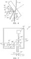
- the energy gun 28" of this first embodiment of the present invention has a beam combinator 82 positioned between a lens 70" and primary and secondary lasers 62", 66".
- the combinator 82 is supported by a housing 60" and is positioned at a prescribed angle 84 with respect to the lens 70" and/or a powder layer 44".
- the angle 84 may be about forty-five degrees with the primary energy source 62" located above the combinator 82 such that an energy beam 64" emitted from the device 62" is directed downward and refracted, first through the combinator 82 and then through the lens 70".
- the energy beam 68" is configured to reflect upon the beam combinator 82, while the energy beam 64" is configured to refract upon the beam combinator 82.
- the device 62", the combinator 82 and the lens 70" are supported by and stationary with respect to the housing 60".
- the plurality of lasers 62", 66" are constructed and arranged to move with respect to the housing 60" to control the distance between the hot spots 72", 74".
- the housing 60" is configured to move at the controlled velocity, such that each one of the plurality of laser beams 64", 68" is configured to impart a hot spot 72", 74" upon the substrate at pre-arranged distances from one-another and the plurality of lasers 62", 66" are configured to move the hot spots 72", 74" in union across the substrate at controlled velocity.
- the secondary energy source device 66" may be positioned such that a secondary energy beam 68" is adjustably directed horizontally to reflect off of the combinator 82 and then refracted through the lens 70".
- movement of the lasers 62", 66" is limited to the fiber optic outputs 96, the fiber optic outputs of each one of the plurality of lasers 62", 66” being pivoted to produce movement of the plurality of lasers 62", 66", thereby relying on the routing capability and flexibility of the fiber optic technology.
- a distance 76" between hot spots 72", 74" may be adjusted by changing the incident reflection angle upon the combinator 82. More specifically, the beam 68" may have a large reflection angle 86 producing a large distance between hot spots 72", 74". Moving or pivoting the energy source device 66" to produce a smaller reflection angle 88 will reduce the distance 76" between hot spots 72", 74". It is further contemplated and understood that the reflected beam 68" may be held stationary and the energy source device 62" emitting the energy beam 64" may be adjustably pivoted or moved to adjust the refraction angle thereby adjusting the distance 76".
- an energy gun 28' has a primary energy beam 64"' that is first focused through a lens 70'" and then refracted through a beam combinator 82"'.
- a secondary energy beam 68'" is first focused through a second lens 80'" and then reflected off of the combinator 82"'.
- a secondary energy source device 66"', emitting the secondary energy beam 68'" is constructed and arranged to pivot or move with respect to a housing 60'" to adjust a distance 76'" between respective hot spots 72"', 74"'.
- a CAD system as part of the controller 38 models the workpiece 36 in a slice-by-slice, stacked orientation.
- a powder bed layer 44 is spread directly over the build table 22 per signals 48 sent from the controller 38.
- the energy gun 28 then melts on a melt pool by melt pool basis a pattern upon the layer 44 mimicking the contour of a bottom slice 46 of the plurality of slices 40 as dictated by the controller 38.
- the melted portion of the powder layer solidifies over a predesignated time interval thereby completing the formation of a bottom slice 46.
- a powder bed layer 44 is spread over the defect-free bottom slice 46.
- step 114 at least a portion of the layer is melted by the energy gun 28 along with a meltback region of the solidified bottom layer 46 in accordance with a CAD pattern of a top slice dictated by the controller 38.
- step 116 the melted layer solidifies forming a top slice.
Claims (10)
- System zur additiven Herstellung zur Produktion eines Werkstücks aus einem Substrat, wobei das System Folgendes umfasst:eine Vielzahl von Lasern (62", 66"; 62"', 66"'), wobei jeder der Vielzahl von Lasern dazu konfiguriert ist, einen jeweiligen von einer Vielzahl von Energiestrahlen (64", 68"; 64"', 68"') zu emittieren;eine Linse (70"; 70"', 80"'), die dazu konfiguriert ist mindestens einen der Vielzahl von Energiestrahlen (64", 68"; 64"', 68"') zu bündeln;eine Strahlenkombiniervorrichtung (82); undein Gehäuse (60"; 60"'), wobei jeder der Vielzahl von Energiestrahlen (64", 68"; 64"', 68"') dazu konfiguriert ist, dem Substrat einen Hotspot (72", 74"; 72"', 74"') bei vorangeordneten Distanzen (76", 76"') voneinander zu verleihen und die Vielzahl von Lasern (62", 66"; 62"', 66"') dazu konfiguriert ist, die Hotspots (72", 74"; 72"', 74"') im Einklang mit einer gesteuerten Geschwindigkeit über das Substrat zu bewegen;wobei mindestens einer der Vielzahl von Energiestrahlen (64", 68"; 64"', 68"') dazu konfiguriert ist, bei der Strahlenkombiniervorrichtung (82) reflektiert zu werden und mindestens einer der Vielzahl von Energiestrahlen (64", 68"; 64"', 68"') dazu konfiguriert ist, bei der Strahlenkombiniervorrichtung (82) gebrochen zu werden;wobei das Gehäuse (60"; 60"') dazu konfiguriert ist, sich mit einer gesteuerten Geschwindigkeit zu bewegen;wobei die Linse (70"; 70"', 80"') und die Strahlenkombiniervorrichtung (82) von dem Gehäuse (60"; 60"') gestützt werden und in Bezug auf dieses stationär sind und die Vielzahl von Lasern (62", 66"; 62"', 66"') dazu konstruiert und angeordnet sind, sich in Bezug auf das Gehäuse (60"; 60"') zu bewegen, um die Distanz (76", 76"') zwischen den Hotspots (72", 74"; 72"', 74"') zu steuern,dadurch gekennzeichnet, dass die Vielzahl von Lasern (62", 66"; 62"', 66"') faseroptische Ausgänge aufweisen (96) und die faseroptischen Ausgänge (96) von jedem der Vielzahl von Lasern (62", 66"; 62"', 66"') geschwenkt werden, um eine Bewegung der Vielzahl von Lasern (62", 66"; 62"', 66"') zu produzieren.
- System zur additiven Herstellung nach Anspruch 1, wobei die Vielzahl von Energiestrahlen (64", 68"; 64"', 68"') einen ersten Energiestrahl, der dazu konfiguriert ist, ein Schmelzbad aus dem Substrat zu produzieren, und einen zweiten Energiestrahl einschließt, wobei der sekundäre Energiestrahl dazu konfiguriert ist, das Substrat wärmenachzubehandeln, um eine Verfestigungsrate des Schmelzbads zu steuern oder das Substrat, das mit dem Schmelzbad assoziiert ist, auf der Basis der Distanz (76", 76"') zwischen den Hotspots (72", 74"; 72"', 74"') wärmevorzubehandeln.
- System zur additiven Herstellung nach Anspruch 1 oder 2, wobei die Vielzahl von Energiestrahlen (64", 68"; 64"', 68"') verschiedene Frequenzen aufweisen.
- System zur additiven Herstellung nach einem der vorhergehenden Ansprüche, wobei die Linse (70", 70"', 80"') dazu konfiguriert ist, die Vielzahl von Energiestrahlen (64", 68"; 64"', 68"') zu bündeln und die Distanz (76", 76"') zwischen den Hotspots (72", 74"; 72"', 74"') vorzuschreiben.
- System zur additiven Herstellung nach einem der vorhergehenden Ansprüche, ferner umfassend:eine Vielzahl von Linsen (70"', 80"'), wobei die Linse eine der Vielzahl von Linsen (70"', 80"') ist; undwobei jede der Vielzahl von Linsen (70"', 80"') durch das Gehäuse (60", 60"') gestützt wird und stationär zu diesem und dazu konfiguriert ist, einen entsprechenden der Vielzahl von Energiestrahlen (64", 68"; 64"', 68"') zu bündeln, und wobei die Vielzahl von Lasern (62", 66"; 62"', 66"') dazu konfiguriert ist, sich in Bezug auf das Gehäuse (60"; 60"') zu bewegen, um die Distanz (76", 76"') zwischen den Hotspots (72", 74"; 72"', 74"') zu steuern.
- System zur additiven Herstellung nach Anspruch 5, wobei jede der Vielzahl von Linsen (70"', 80"') sich zwischen der Strahlenkombiniervorrichtung (82) und den jeweiligen Lasern (62"', 66"') befindet.
- System zur additiven Herstellung nach einem der vorhergehenden Ansprüche, wobei die Strahlenkombiniervorrichtung (82) zwischen der Vielzahl von Lasern (62", 66"; 62"', 66"') und der Linse (70"; 70"'; 80"') ausgerichtet ist.
- System zur additiven Herstellung nach einem der vorhergehenden Ansprüche, ferner umfassend:einen Aufbautisch (22), der dazu konfiguriert ist, ein Pulverbett (24) zu stützen; undeine Steuerung (38), die dazu konfiguriert ist, das Werkstück (36) als eine Vielzahl von Scheiben (40) zu modellieren, die additiv übereinander aufgebaut werden, wobei jede Scheibe (40) einer Schicht (44") des Pulverbetts (24) vor einer Verfestigung der Scheibe (40) entspricht.
- Verfahren zur additiven Herstellung eines Werkstücks, das die folgenden Schritte umfasst:Schmelzen eines Substrats in ein Schmelzbad mit einem ersten Hotspot (72"; 72"') der einem Substrat durch einen ersten Energiestrahl (64"; 64"') verliehen wird, der von einem ersten Laser (62"; 62"') emittiert wird;Wärmekonditionieren des Substrats mit einem zweiten Hotspot (74"; 74"'), der einem Substrat von einem zweiten Energiestrahl (68"; 68"') verliehen wird, der von einem zweiten Laser (66"; 66"') emittiert wird;Bündeln mit einer Linse (70"; 70"', 80"') von mindestens einem von dem ersten Energiestrahl (64"; 64"') und dem zweiten Energiestrahl (68"; 68"');Reflektieren von einem von dem ersten Energiestrahl (64"; 64"') und dem zweiten Energiestrahl (68"; 68"') bei der Strahlenkombiniervorrichtung (82) und Brechen des anderen von dem ersten Energiestrahl (64"; 64"') und dem zweiten Energiestrahl (68"; 68"') bei der Strahlenkombiniervorrichtung (82);Bewegen eines Gehäuses (60"; 60"') mit einer gesteuerten Geschwindigkeit;Bewegen von mindestens einem der Laser (62", 66"; 62"', 66"') in Bezug auf das Gehäuse (60", 60"'), um eine Distanz (76", 76"') zwischen dem ersten und dem zweiten Hotspot (72", 74"; 72"', 74"') zu steuern;Bewegen der Hotspots (72", 74"; 72"', 74"') im Einklang über das Substrat mit einer gesteuerten Geschwindigkeit; und Stützen der Linse (70"; 70"', 80"') und der Strahlenkombiniervorrichtung (82) mit dem Gehäuse (60"; 60"'); wobei die Linse (70"; 70"', 80"') und die Strahlenkombiniervorrichtung (82) in Bezug auf das Gehäuse (60"; 60"') stationär sind,dadurch gekennzeichnet, dass der erste Laser (62"; 62"') und der zweite Laser (66"; 66"') jeweils einen faseroptischen Ausgang (96) aufweisen, die geschwenkt werden, um eine Bewegung des ersten Lasers (62"; 62"') und des zweiten Lasers (66"; 66"') zu produzieren.
- Verfahren nach Anspruch 9, ferner umfassend:
Vorwärmen einer Region des Substrats mit dem zweiten Energiestrahl (68"; 68"') vor dem Schmelzen der Region in das Schmelzbad durch den ersten Energiestrahl (64"; 64"').
Applications Claiming Priority (2)
| Application Number | Priority Date | Filing Date | Title |
|---|---|---|---|
| US201461936652P | 2014-02-06 | 2014-02-06 | |
| PCT/US2015/014649 WO2015120168A1 (en) | 2014-02-06 | 2015-02-05 | An additive manufacturing system with a multi-energy beam gun and method of operation |
Publications (3)
| Publication Number | Publication Date |
|---|---|
| EP3102389A1 EP3102389A1 (de) | 2016-12-14 |
| EP3102389A4 EP3102389A4 (de) | 2017-02-22 |
| EP3102389B1 true EP3102389B1 (de) | 2019-08-28 |
Family
ID=53778448
Family Applications (1)
| Application Number | Title | Priority Date | Filing Date |
|---|---|---|---|
| EP15745849.8A Active EP3102389B1 (de) | 2014-02-06 | 2015-02-05 | System zur additiven fertigung mit mehrlaserstrahlpistole und verfahren zum betrieb |
Country Status (3)
| Country | Link |
|---|---|
| US (1) | US20170008126A1 (de) |
| EP (1) | EP3102389B1 (de) |
| WO (1) | WO2015120168A1 (de) |
Families Citing this family (70)
| Publication number | Priority date | Publication date | Assignee | Title |
|---|---|---|---|---|
| EP2454039B1 (de) | 2009-07-15 | 2014-09-03 | Arcam Ab | Verfahren zur herstellung von dreidimensionalen objekten |
| GB2489493B (en) | 2011-03-31 | 2013-03-13 | Norsk Titanium Components As | Method and arrangement for building metallic objects by solid freeform fabrication |
| US10144063B2 (en) | 2011-12-28 | 2018-12-04 | Arcam Ab | Method and apparatus for detecting defects in freeform fabrication |
| CN104066536B (zh) | 2011-12-28 | 2016-12-14 | 阿卡姆股份公司 | 用于制造多孔三维物品的方法 |
| US9718129B2 (en) | 2012-12-17 | 2017-08-01 | Arcam Ab | Additive manufacturing method and apparatus |
| US9676032B2 (en) | 2013-09-20 | 2017-06-13 | Arcam Ab | Method for additive manufacturing |
| US10434572B2 (en) | 2013-12-19 | 2019-10-08 | Arcam Ab | Method for additive manufacturing |
| US9802253B2 (en) | 2013-12-16 | 2017-10-31 | Arcam Ab | Additive manufacturing of three-dimensional articles |
| US10130993B2 (en) | 2013-12-18 | 2018-11-20 | Arcam Ab | Additive manufacturing of three-dimensional articles |
| US9789541B2 (en) | 2014-03-07 | 2017-10-17 | Arcam Ab | Method for additive manufacturing of three-dimensional articles |
| US20150283613A1 (en) | 2014-04-02 | 2015-10-08 | Arcam Ab | Method for fusing a workpiece |
| US20160167303A1 (en) | 2014-12-15 | 2016-06-16 | Arcam Ab | Slicing method |
| US9406483B1 (en) | 2015-01-21 | 2016-08-02 | Arcam Ab | Method and device for characterizing an electron beam using an X-ray detector with a patterned aperture resolver and patterned aperture modulator |
| US11014161B2 (en) | 2015-04-21 | 2021-05-25 | Arcam Ab | Method for additive manufacturing |
| US10807187B2 (en) | 2015-09-24 | 2020-10-20 | Arcam Ab | X-ray calibration standard object |
| US10220471B2 (en) | 2015-10-14 | 2019-03-05 | Lawrence Livermore National Security, Llc | Spatter reduction laser scanning strategy in selective laser melting |
| US11571748B2 (en) | 2015-10-15 | 2023-02-07 | Arcam Ab | Method and apparatus for producing a three-dimensional article |
| WO2017075258A1 (en) | 2015-10-30 | 2017-05-04 | Seurat Technologies, Inc. | Additive manufacturing system and method |
| US10525531B2 (en) | 2015-11-17 | 2020-01-07 | Arcam Ab | Additive manufacturing of three-dimensional articles |
| US10610930B2 (en) * | 2015-11-18 | 2020-04-07 | Arcam Ab | Additive manufacturing of three-dimensional articles |
| EP3383573B1 (de) | 2015-12-04 | 2023-11-08 | Raytheon Company | Generative fertigung mit elektronenstrahlen |
| US11701819B2 (en) * | 2016-01-28 | 2023-07-18 | Seurat Technologies, Inc. | Additive manufacturing, spatial heat treating system and method |
| US11148319B2 (en) | 2016-01-29 | 2021-10-19 | Seurat Technologies, Inc. | Additive manufacturing, bond modifying system and method |
| US11247274B2 (en) | 2016-03-11 | 2022-02-15 | Arcam Ab | Method and apparatus for forming a three-dimensional article |
| DE102016204905A1 (de) * | 2016-03-23 | 2017-09-28 | Eos Gmbh Electro Optical Systems | Verfahren und Vorrichtung zum Herstellen eines dreidimensionalen Objekts |
| US20170326867A1 (en) * | 2016-05-10 | 2017-11-16 | Resonetics, LLC | Hybrid micro-manufacturing |
| US10549348B2 (en) | 2016-05-24 | 2020-02-04 | Arcam Ab | Method for additive manufacturing |
| US11325191B2 (en) | 2016-05-24 | 2022-05-10 | Arcam Ab | Method for additive manufacturing |
| US10525547B2 (en) | 2016-06-01 | 2020-01-07 | Arcam Ab | Additive manufacturing of three-dimensional articles |
| US11691343B2 (en) | 2016-06-29 | 2023-07-04 | Velo3D, Inc. | Three-dimensional printing and three-dimensional printers |
| EP3481579A1 (de) * | 2016-07-08 | 2019-05-15 | Norsk Titanium AS | Verfahren und anordnung zur herstellung von metallischen gegenständen durch festkörperfreiformherstellung mit zwei widerstandsschweisspistolen |
| EP3281725A1 (de) * | 2016-08-09 | 2018-02-14 | Siemens Aktiengesellschaft | Verfahren zur additiven fertigung und computerlesbares medium |
| DE102016120044A1 (de) * | 2016-10-20 | 2018-04-26 | Cl Schutzrechtsverwaltungs Gmbh | Vorrichtung zur additiven Herstellung dreidimensionaler Objekte |
| US10792757B2 (en) * | 2016-10-25 | 2020-10-06 | Arcam Ab | Method and apparatus for additive manufacturing |
| DE102016122368A1 (de) * | 2016-11-21 | 2018-05-24 | Cl Schutzrechtsverwaltungs Gmbh | Verfahren zur additiven Herstellung eines dreidimensionalen Objekts |
| US20180141160A1 (en) | 2016-11-21 | 2018-05-24 | General Electric Company | In-line laser scanner for controlled cooling rates of direct metal laser melting |
| US11485083B2 (en) * | 2016-12-18 | 2022-11-01 | Csir | Preheating of material in an additive manufacturing apparatus |
| US10987752B2 (en) | 2016-12-21 | 2021-04-27 | Arcam Ab | Additive manufacturing of three-dimensional articles |
| US20180186073A1 (en) * | 2017-01-03 | 2018-07-05 | General Electric Company | Additive manufacturing systems including a particulate dispenser and methods of operating such systems |
| US20180200791A1 (en) * | 2017-01-13 | 2018-07-19 | General Electric Company | Dynamically damped recoater |
| CN106735219A (zh) * | 2017-01-17 | 2017-05-31 | 华南理工大学 | 一种轮盘式多材料激光选区熔化成型装置与方法 |
| WO2018140592A1 (en) * | 2017-01-25 | 2018-08-02 | Arconic Inc. | Additively manufactured parts and related methods |
| DE102017105056A1 (de) * | 2017-03-09 | 2018-09-13 | Cl Schutzrechtsverwaltungs Gmbh | Vorrichtung zur additiven Herstellung dreidimensionaler Objekte |
| EP3600836B1 (de) | 2017-03-29 | 2022-11-23 | Hewlett-Packard Development Company, L.P. | Energiedosierung für die generativen fertigung |
| US20180304539A1 (en) * | 2017-04-21 | 2018-10-25 | Applied Materials, Inc. | Energy delivery system with array of energy sources for an additive manufacturing apparatus |
| US20210206079A1 (en) * | 2017-04-25 | 2021-07-08 | Hewlett-Packard Development Company, L.P. | Additive manufacturing machine optical filter |
| US10857735B1 (en) * | 2017-04-25 | 2020-12-08 | Hrl Laboratories, Llc | Apparatus and method for additive manufacturing and determining the development of stress during additive manufacturing |
| US11059123B2 (en) | 2017-04-28 | 2021-07-13 | Arcam Ab | Additive manufacturing of three-dimensional articles |
| US11014302B2 (en) | 2017-05-11 | 2021-05-25 | Seurat Technologies, Inc. | Switchyard beam routing of patterned light for additive manufacturing |
| US11292062B2 (en) | 2017-05-30 | 2022-04-05 | Arcam Ab | Method and device for producing three-dimensional objects |
| SI25442A (sl) | 2017-06-13 | 2018-12-31 | Mušević Nataša | Naprava in postopek za aditivno izdelovanje tridimenzionalnih objektov |
| US11097350B2 (en) | 2017-07-24 | 2021-08-24 | Raytheon Technologies Corporation | Pre-fusion laser sintering for metal powder stabilization during additive manufacturing |
| US10766242B2 (en) * | 2017-08-24 | 2020-09-08 | General Electric Company | System and methods for fabricating a component using a consolidating device |
| US20190099809A1 (en) | 2017-09-29 | 2019-04-04 | Arcam Ab | Method and apparatus for additive manufacturing |
| US10529070B2 (en) | 2017-11-10 | 2020-01-07 | Arcam Ab | Method and apparatus for detecting electron beam source filament wear |
| US10821721B2 (en) | 2017-11-27 | 2020-11-03 | Arcam Ab | Method for analysing a build layer |
| US11072117B2 (en) | 2017-11-27 | 2021-07-27 | Arcam Ab | Platform device |
| US11517975B2 (en) | 2017-12-22 | 2022-12-06 | Arcam Ab | Enhanced electron beam generation |
| CN109986077B (zh) * | 2018-01-02 | 2022-05-06 | 通用电气公司 | 增材制造系统及增材制造方法 |
| EP3524409A1 (de) * | 2018-02-09 | 2019-08-14 | CL Schutzrechtsverwaltungs GmbH | Vorrichtung zur generativen fertigung dreidimensionaler objekte |
| US11458682B2 (en) | 2018-02-27 | 2022-10-04 | Arcam Ab | Compact build tank for an additive manufacturing apparatus |
| US11267051B2 (en) | 2018-02-27 | 2022-03-08 | Arcam Ab | Build tank for an additive manufacturing apparatus |
| US11224943B2 (en) * | 2018-03-07 | 2022-01-18 | Divergent Technologies, Inc. | Variable beam geometry laser-based powder bed fusion |
| US10695867B2 (en) | 2018-03-08 | 2020-06-30 | General Electric Company | Controlling microstructure of selected range of layers of object during additive manufacture |
| US11400519B2 (en) | 2018-03-29 | 2022-08-02 | Arcam Ab | Method and device for distributing powder material |
| US11426818B2 (en) | 2018-08-10 | 2022-08-30 | The Research Foundation for the State University | Additive manufacturing processes and additively manufactured products |
| US11541481B2 (en) | 2018-12-19 | 2023-01-03 | Seurat Technologies, Inc. | Additive manufacturing system using a pulse modulated laser for two-dimensional printing |
| US11925985B2 (en) * | 2019-06-26 | 2024-03-12 | Hamilton Sundstrand Corporation | Method of making a radial turbine wheel using additive manufacturing |
| US11726069B2 (en) * | 2020-09-22 | 2023-08-15 | Corvid Technologies LLC | Methods and systems for evaluating a target using pulsed, energetic particle beams |
| CN116984631A (zh) * | 2023-09-20 | 2023-11-03 | 苏州倍丰智能科技有限公司 | 一种集成式多激光定向扫描的3d打印系统及方法 |
Family Cites Families (15)
| Publication number | Priority date | Publication date | Assignee | Title |
|---|---|---|---|---|
| GB9009073D0 (en) * | 1990-04-23 | 1990-06-20 | Insituform Group Ltd | Improvements relating to the lining of pipelines or passageways |
| US5393482A (en) * | 1993-10-20 | 1995-02-28 | United Technologies Corporation | Method for performing multiple beam laser sintering employing focussed and defocussed laser beams |
| US5640667A (en) * | 1995-11-27 | 1997-06-17 | Board Of Regents, The University Of Texas System | Laser-directed fabrication of full-density metal articles using hot isostatic processing |
| US5866058A (en) * | 1997-05-29 | 1999-02-02 | Stratasys Inc. | Method for rapid prototyping of solid models |
| DE19953000C2 (de) * | 1999-11-04 | 2003-04-10 | Horst Exner | Verfahren und Einrichtung zur schnellen Herstellung von Körpern |
| DE112005001418T5 (de) * | 2004-06-18 | 2008-02-21 | Electro Scientific Industries, Inc., Portland | Halbleiterstruktur-Bearbeitung unter Verwendung von mehreren Laserstrahlpunkten |
| DE102005015870B3 (de) * | 2005-04-06 | 2006-10-26 | Eos Gmbh Electro Optical Systems | Vorrichtung und Verfahren zum Herstellen eines dreidimensionalen Objekts |
| JP4800661B2 (ja) * | 2005-05-09 | 2011-10-26 | 株式会社ディスコ | レーザ光線を利用する加工装置 |
| WO2007147221A1 (en) * | 2006-06-20 | 2007-12-27 | Katholieke Universiteit Leuven | Procedure and apparatus for in-situ monitoring and feedback control of selective laser powder processing |
| SG173534A1 (en) * | 2009-02-10 | 2011-09-29 | Bae Systems Plc | Method of fabricating an object |
| US9283593B2 (en) * | 2011-01-13 | 2016-03-15 | Siemens Energy, Inc. | Selective laser melting / sintering using powdered flux |
| FR2980380B1 (fr) * | 2011-09-23 | 2015-03-06 | Snecma | Strategie de fabrication d'une piece metallique par fusion selective d'une poudre |
| US9419502B2 (en) * | 2012-08-03 | 2016-08-16 | Hamilton Sundstrand Corporation | Additive manufacturing of a component having a laminated stack of layers |
| WO2014047514A1 (en) * | 2012-09-21 | 2014-03-27 | Conformis, Inc. | Methods and systems for optimizing design and manufacture of implant components using solid freeform fabrication |
| US20150064047A1 (en) * | 2013-08-28 | 2015-03-05 | Elwha Llc | Systems and methods for additive manufacturing of three dimensional structures |
-
2015
- 2015-02-05 EP EP15745849.8A patent/EP3102389B1/de active Active
- 2015-02-05 WO PCT/US2015/014649 patent/WO2015120168A1/en active Application Filing
- 2015-02-05 US US15/113,499 patent/US20170008126A1/en not_active Abandoned
Non-Patent Citations (1)
| Title |
|---|
| None * |
Also Published As
| Publication number | Publication date |
|---|---|
| EP3102389A4 (de) | 2017-02-22 |
| WO2015120168A1 (en) | 2015-08-13 |
| US20170008126A1 (en) | 2017-01-12 |
| EP3102389A1 (de) | 2016-12-14 |
Similar Documents
| Publication | Publication Date | Title |
|---|---|---|
| EP3102389B1 (de) | System zur additiven fertigung mit mehrlaserstrahlpistole und verfahren zum betrieb | |
| US11020955B2 (en) | Control of solidification in laser powder bed fusion additive manufacturing using a diode laser fiber array | |
| US11027536B2 (en) | Diode laser fiber array for powder bed fabrication or repair | |
| EP3554749B1 (de) | Systeme und verfahren zur generativen fertigung | |
| CN105562688B (zh) | 通过选择性的激光熔化来制造构件 | |
| KR102444026B1 (ko) | 다중 빔 적층 제조 | |
| EP3554795B1 (de) | Systeme und verfahren zur generativen fertigung | |
| JP6553102B2 (ja) | ダイオードレーザファイバーアレイを用いたレーザ粉体床溶融結合付加製造における凝固制御法 | |
| US20190224913A1 (en) | Production of three-dimensional workpieces by means of a plurality of irradiation units | |
| GB2490143A (en) | Method of manufacturing a component using a laser | |
| US20180369961A1 (en) | Treatment of solidified layer | |
| CN113165108A (zh) | 用能量射束照射材料的方法和装置 | |
| EP3434396A1 (de) | Präfusionslasersintern zur metallpulverstabilisierung während der generativen fertigung | |
| CN110733176A (zh) | 光束整形机构、激光光源系统、激光3d打印设备和方法 | |
| US20220097174A1 (en) | Variable beam geometry laser-based powder bed fusion | |
| KR20210147194A (ko) | 등가적층 체적높이 제어방법 | |
| CN112387966B (zh) | 用于大规模增材制造的系统和方法 | |
| WO2023042341A1 (ja) | 造形システム | |
| JP2021042453A (ja) | コーティング方法及びコーティング構造 |
Legal Events
| Date | Code | Title | Description |
|---|---|---|---|
| PUAI | Public reference made under article 153(3) epc to a published international application that has entered the european phase |
Free format text: ORIGINAL CODE: 0009012 |
|
| STAA | Information on the status of an ep patent application or granted ep patent |
Free format text: STATUS: REQUEST FOR EXAMINATION WAS MADE |
|
| 17P | Request for examination filed |
Effective date: 20160905 |
|
| AK | Designated contracting states |
Kind code of ref document: A1 Designated state(s): AL AT BE BG CH CY CZ DE DK EE ES FI FR GB GR HR HU IE IS IT LI LT LU LV MC MK MT NL NO PL PT RO RS SE SI SK SM TR |
|
| AX | Request for extension of the european patent |
Extension state: BA ME |
|
| RIN1 | Information on inventor provided before grant (corrected) |
Inventor name: LONG, YU Inventor name: ZHANG, YAN Inventor name: BEALS, JAMES T. |
|
| A4 | Supplementary search report drawn up and despatched |
Effective date: 20170124 |
|
| RIC1 | Information provided on ipc code assigned before grant |
Ipc: B23K 26/06 20140101ALI20170118BHEP Ipc: B33Y 30/00 20150101ALI20170118BHEP Ipc: B22F 3/105 20060101ALI20170118BHEP Ipc: B29C 67/00 20170101AFI20170118BHEP |
|
| DAX | Request for extension of the european patent (deleted) | ||
| STAA | Information on the status of an ep patent application or granted ep patent |
Free format text: STATUS: EXAMINATION IS IN PROGRESS |
|
| 17Q | First examination report despatched |
Effective date: 20180216 |
|
| REG | Reference to a national code |
Ref country code: DE Ref legal event code: R079 Ref document number: 602015036737 Country of ref document: DE Free format text: PREVIOUS MAIN CLASS: B29C0067000000 Ipc: B29C0064153000 |
|
| GRAP | Despatch of communication of intention to grant a patent |
Free format text: ORIGINAL CODE: EPIDOSNIGR1 |
|
| STAA | Information on the status of an ep patent application or granted ep patent |
Free format text: STATUS: GRANT OF PATENT IS INTENDED |
|
| RIC1 | Information provided on ipc code assigned before grant |
Ipc: B33Y 30/00 20150101ALI20180904BHEP Ipc: C21D 10/00 20060101ALI20180904BHEP Ipc: C22F 3/02 20060101ALI20180904BHEP Ipc: B22F 3/105 20060101ALI20180904BHEP Ipc: B29C 64/153 20170101AFI20180904BHEP Ipc: B23K 26/08 20140101ALI20180904BHEP Ipc: B29C 64/20 20170101ALI20180904BHEP Ipc: B23K 26/342 20140101ALI20180904BHEP Ipc: B23K 26/06 20140101ALI20180904BHEP |
|
| INTG | Intention to grant announced |
Effective date: 20181005 |
|
| GRAJ | Information related to disapproval of communication of intention to grant by the applicant or resumption of examination proceedings by the epo deleted |
Free format text: ORIGINAL CODE: EPIDOSDIGR1 |
|
| STAA | Information on the status of an ep patent application or granted ep patent |
Free format text: STATUS: EXAMINATION IS IN PROGRESS |
|
| GRAP | Despatch of communication of intention to grant a patent |
Free format text: ORIGINAL CODE: EPIDOSNIGR1 |
|
| STAA | Information on the status of an ep patent application or granted ep patent |
Free format text: STATUS: GRANT OF PATENT IS INTENDED |
|
| INTC | Intention to grant announced (deleted) | ||
| INTG | Intention to grant announced |
Effective date: 20190311 |
|
| GRAS | Grant fee paid |
Free format text: ORIGINAL CODE: EPIDOSNIGR3 |
|
| GRAA | (expected) grant |
Free format text: ORIGINAL CODE: 0009210 |
|
| STAA | Information on the status of an ep patent application or granted ep patent |
Free format text: STATUS: THE PATENT HAS BEEN GRANTED |
|
| AK | Designated contracting states |
Kind code of ref document: B1 Designated state(s): AL AT BE BG CH CY CZ DE DK EE ES FI FR GB GR HR HU IE IS IT LI LT LU LV MC MK MT NL NO PL PT RO RS SE SI SK SM TR |
|
| REG | Reference to a national code |
Ref country code: GB Ref legal event code: FG4D |
|
| REG | Reference to a national code |
Ref country code: CH Ref legal event code: EP |
|
| REG | Reference to a national code |
Ref country code: AT Ref legal event code: REF Ref document number: 1171870 Country of ref document: AT Kind code of ref document: T Effective date: 20190915 |
|
| REG | Reference to a national code |
Ref country code: IE Ref legal event code: FG4D |
|
| REG | Reference to a national code |
Ref country code: DE Ref legal event code: R096 Ref document number: 602015036737 Country of ref document: DE |
|
| REG | Reference to a national code |
Ref country code: NL Ref legal event code: MP Effective date: 20190828 |
|
| REG | Reference to a national code |
Ref country code: LT Ref legal event code: MG4D |
|
| PG25 | Lapsed in a contracting state [announced via postgrant information from national office to epo] |
Ref country code: NO Free format text: LAPSE BECAUSE OF FAILURE TO SUBMIT A TRANSLATION OF THE DESCRIPTION OR TO PAY THE FEE WITHIN THE PRESCRIBED TIME-LIMIT Effective date: 20191128 Ref country code: BG Free format text: LAPSE BECAUSE OF FAILURE TO SUBMIT A TRANSLATION OF THE DESCRIPTION OR TO PAY THE FEE WITHIN THE PRESCRIBED TIME-LIMIT Effective date: 20191128 Ref country code: LT Free format text: LAPSE BECAUSE OF FAILURE TO SUBMIT A TRANSLATION OF THE DESCRIPTION OR TO PAY THE FEE WITHIN THE PRESCRIBED TIME-LIMIT Effective date: 20190828 Ref country code: PT Free format text: LAPSE BECAUSE OF FAILURE TO SUBMIT A TRANSLATION OF THE DESCRIPTION OR TO PAY THE FEE WITHIN THE PRESCRIBED TIME-LIMIT Effective date: 20191230 Ref country code: NL Free format text: LAPSE BECAUSE OF FAILURE TO SUBMIT A TRANSLATION OF THE DESCRIPTION OR TO PAY THE FEE WITHIN THE PRESCRIBED TIME-LIMIT Effective date: 20190828 Ref country code: FI Free format text: LAPSE BECAUSE OF FAILURE TO SUBMIT A TRANSLATION OF THE DESCRIPTION OR TO PAY THE FEE WITHIN THE PRESCRIBED TIME-LIMIT Effective date: 20190828 Ref country code: SE Free format text: LAPSE BECAUSE OF FAILURE TO SUBMIT A TRANSLATION OF THE DESCRIPTION OR TO PAY THE FEE WITHIN THE PRESCRIBED TIME-LIMIT Effective date: 20190828 Ref country code: HR Free format text: LAPSE BECAUSE OF FAILURE TO SUBMIT A TRANSLATION OF THE DESCRIPTION OR TO PAY THE FEE WITHIN THE PRESCRIBED TIME-LIMIT Effective date: 20190828 |
|
| PG25 | Lapsed in a contracting state [announced via postgrant information from national office to epo] |
Ref country code: AL Free format text: LAPSE BECAUSE OF FAILURE TO SUBMIT A TRANSLATION OF THE DESCRIPTION OR TO PAY THE FEE WITHIN THE PRESCRIBED TIME-LIMIT Effective date: 20190828 Ref country code: GR Free format text: LAPSE BECAUSE OF FAILURE TO SUBMIT A TRANSLATION OF THE DESCRIPTION OR TO PAY THE FEE WITHIN THE PRESCRIBED TIME-LIMIT Effective date: 20191129 Ref country code: RS Free format text: LAPSE BECAUSE OF FAILURE TO SUBMIT A TRANSLATION OF THE DESCRIPTION OR TO PAY THE FEE WITHIN THE PRESCRIBED TIME-LIMIT Effective date: 20190828 Ref country code: IS Free format text: LAPSE BECAUSE OF FAILURE TO SUBMIT A TRANSLATION OF THE DESCRIPTION OR TO PAY THE FEE WITHIN THE PRESCRIBED TIME-LIMIT Effective date: 20191228 Ref country code: LV Free format text: LAPSE BECAUSE OF FAILURE TO SUBMIT A TRANSLATION OF THE DESCRIPTION OR TO PAY THE FEE WITHIN THE PRESCRIBED TIME-LIMIT Effective date: 20190828 Ref country code: ES Free format text: LAPSE BECAUSE OF FAILURE TO SUBMIT A TRANSLATION OF THE DESCRIPTION OR TO PAY THE FEE WITHIN THE PRESCRIBED TIME-LIMIT Effective date: 20190828 |
|
| REG | Reference to a national code |
Ref country code: AT Ref legal event code: MK05 Ref document number: 1171870 Country of ref document: AT Kind code of ref document: T Effective date: 20190828 |
|
| PG25 | Lapsed in a contracting state [announced via postgrant information from national office to epo] |
Ref country code: TR Free format text: LAPSE BECAUSE OF FAILURE TO SUBMIT A TRANSLATION OF THE DESCRIPTION OR TO PAY THE FEE WITHIN THE PRESCRIBED TIME-LIMIT Effective date: 20190828 |
|
| PG25 | Lapsed in a contracting state [announced via postgrant information from national office to epo] |
Ref country code: IT Free format text: LAPSE BECAUSE OF FAILURE TO SUBMIT A TRANSLATION OF THE DESCRIPTION OR TO PAY THE FEE WITHIN THE PRESCRIBED TIME-LIMIT Effective date: 20190828 Ref country code: DK Free format text: LAPSE BECAUSE OF FAILURE TO SUBMIT A TRANSLATION OF THE DESCRIPTION OR TO PAY THE FEE WITHIN THE PRESCRIBED TIME-LIMIT Effective date: 20190828 Ref country code: AT Free format text: LAPSE BECAUSE OF FAILURE TO SUBMIT A TRANSLATION OF THE DESCRIPTION OR TO PAY THE FEE WITHIN THE PRESCRIBED TIME-LIMIT Effective date: 20190828 Ref country code: EE Free format text: LAPSE BECAUSE OF FAILURE TO SUBMIT A TRANSLATION OF THE DESCRIPTION OR TO PAY THE FEE WITHIN THE PRESCRIBED TIME-LIMIT Effective date: 20190828 Ref country code: PL Free format text: LAPSE BECAUSE OF FAILURE TO SUBMIT A TRANSLATION OF THE DESCRIPTION OR TO PAY THE FEE WITHIN THE PRESCRIBED TIME-LIMIT Effective date: 20190828 Ref country code: RO Free format text: LAPSE BECAUSE OF FAILURE TO SUBMIT A TRANSLATION OF THE DESCRIPTION OR TO PAY THE FEE WITHIN THE PRESCRIBED TIME-LIMIT Effective date: 20190828 |
|
| PG25 | Lapsed in a contracting state [announced via postgrant information from national office to epo] |
Ref country code: CZ Free format text: LAPSE BECAUSE OF FAILURE TO SUBMIT A TRANSLATION OF THE DESCRIPTION OR TO PAY THE FEE WITHIN THE PRESCRIBED TIME-LIMIT Effective date: 20190828 Ref country code: SM Free format text: LAPSE BECAUSE OF FAILURE TO SUBMIT A TRANSLATION OF THE DESCRIPTION OR TO PAY THE FEE WITHIN THE PRESCRIBED TIME-LIMIT Effective date: 20190828 Ref country code: SK Free format text: LAPSE BECAUSE OF FAILURE TO SUBMIT A TRANSLATION OF THE DESCRIPTION OR TO PAY THE FEE WITHIN THE PRESCRIBED TIME-LIMIT Effective date: 20190828 Ref country code: IS Free format text: LAPSE BECAUSE OF FAILURE TO SUBMIT A TRANSLATION OF THE DESCRIPTION OR TO PAY THE FEE WITHIN THE PRESCRIBED TIME-LIMIT Effective date: 20200224 |
|
| REG | Reference to a national code |
Ref country code: DE Ref legal event code: R097 Ref document number: 602015036737 Country of ref document: DE |
|
| PLBE | No opposition filed within time limit |
Free format text: ORIGINAL CODE: 0009261 |
|
| STAA | Information on the status of an ep patent application or granted ep patent |
Free format text: STATUS: NO OPPOSITION FILED WITHIN TIME LIMIT |
|
| PG2D | Information on lapse in contracting state deleted |
Ref country code: IS |
|
| 26N | No opposition filed |
Effective date: 20200603 |
|
| PG25 | Lapsed in a contracting state [announced via postgrant information from national office to epo] |
Ref country code: SI Free format text: LAPSE BECAUSE OF FAILURE TO SUBMIT A TRANSLATION OF THE DESCRIPTION OR TO PAY THE FEE WITHIN THE PRESCRIBED TIME-LIMIT Effective date: 20190828 |
|
| REG | Reference to a national code |
Ref country code: CH Ref legal event code: PL |
|
| REG | Reference to a national code |
Ref country code: BE Ref legal event code: MM Effective date: 20200229 |
|
| PG25 | Lapsed in a contracting state [announced via postgrant information from national office to epo] |
Ref country code: LU Free format text: LAPSE BECAUSE OF NON-PAYMENT OF DUE FEES Effective date: 20200205 Ref country code: MC Free format text: LAPSE BECAUSE OF FAILURE TO SUBMIT A TRANSLATION OF THE DESCRIPTION OR TO PAY THE FEE WITHIN THE PRESCRIBED TIME-LIMIT Effective date: 20190828 |
|
| PG25 | Lapsed in a contracting state [announced via postgrant information from national office to epo] |
Ref country code: LI Free format text: LAPSE BECAUSE OF NON-PAYMENT OF DUE FEES Effective date: 20200229 Ref country code: CH Free format text: LAPSE BECAUSE OF NON-PAYMENT OF DUE FEES Effective date: 20200229 |
|
| PG25 | Lapsed in a contracting state [announced via postgrant information from national office to epo] |
Ref country code: IE Free format text: LAPSE BECAUSE OF NON-PAYMENT OF DUE FEES Effective date: 20200205 |
|
| PG25 | Lapsed in a contracting state [announced via postgrant information from national office to epo] |
Ref country code: BE Free format text: LAPSE BECAUSE OF NON-PAYMENT OF DUE FEES Effective date: 20200229 |
|
| PG25 | Lapsed in a contracting state [announced via postgrant information from national office to epo] |
Ref country code: MT Free format text: LAPSE BECAUSE OF FAILURE TO SUBMIT A TRANSLATION OF THE DESCRIPTION OR TO PAY THE FEE WITHIN THE PRESCRIBED TIME-LIMIT Effective date: 20190828 Ref country code: CY Free format text: LAPSE BECAUSE OF FAILURE TO SUBMIT A TRANSLATION OF THE DESCRIPTION OR TO PAY THE FEE WITHIN THE PRESCRIBED TIME-LIMIT Effective date: 20190828 |
|
| PG25 | Lapsed in a contracting state [announced via postgrant information from national office to epo] |
Ref country code: MK Free format text: LAPSE BECAUSE OF FAILURE TO SUBMIT A TRANSLATION OF THE DESCRIPTION OR TO PAY THE FEE WITHIN THE PRESCRIBED TIME-LIMIT Effective date: 20190828 |
|
| REG | Reference to a national code |
Ref country code: DE Ref legal event code: R081 Ref document number: 602015036737 Country of ref document: DE Owner name: RAYTHEON TECHNOLOGIES CORPORATION (N.D.GES.D.S, US Free format text: FORMER OWNER: UNITED TECHNOLOGIES CORPORATION, FARMINGTON, CONN., US |
|
| PGFP | Annual fee paid to national office [announced via postgrant information from national office to epo] |
Ref country code: FR Payment date: 20230119 Year of fee payment: 9 |
|
| PGFP | Annual fee paid to national office [announced via postgrant information from national office to epo] |
Ref country code: GB Payment date: 20230121 Year of fee payment: 9 Ref country code: DE Payment date: 20230119 Year of fee payment: 9 |
|
| P01 | Opt-out of the competence of the unified patent court (upc) registered |
Effective date: 20230520 |