EP3101669B1 - Mécanisme de neutralisation d'actionneur pour disjoncteur sous-marin - Google Patents
Mécanisme de neutralisation d'actionneur pour disjoncteur sous-marin Download PDFInfo
- Publication number
- EP3101669B1 EP3101669B1 EP15170751.0A EP15170751A EP3101669B1 EP 3101669 B1 EP3101669 B1 EP 3101669B1 EP 15170751 A EP15170751 A EP 15170751A EP 3101669 B1 EP3101669 B1 EP 3101669B1
- Authority
- EP
- European Patent Office
- Prior art keywords
- circuit breaker
- subsea
- enclosure
- mechanical
- magnetic
- Prior art date
- Legal status (The legal status is an assumption and is not a legal conclusion. Google has not performed a legal analysis and makes no representation as to the accuracy of the status listed.)
- Active
Links
Images
Classifications
-
- H—ELECTRICITY
- H01—ELECTRIC ELEMENTS
- H01H—ELECTRIC SWITCHES; RELAYS; SELECTORS; EMERGENCY PROTECTIVE DEVICES
- H01H71/00—Details of the protective switches or relays covered by groups H01H73/00 - H01H83/00
- H01H71/10—Operating or release mechanisms
- H01H71/12—Automatic release mechanisms with or without manual release
- H01H71/24—Electromagnetic mechanisms
-
- H—ELECTRICITY
- H01—ELECTRIC ELEMENTS
- H01H—ELECTRIC SWITCHES; RELAYS; SELECTORS; EMERGENCY PROTECTIVE DEVICES
- H01H3/00—Mechanisms for operating contacts
- H01H3/54—Mechanisms for coupling or uncoupling operating parts, driving mechanisms, or contacts
- H01H3/56—Mechanisms for coupling or uncoupling operating parts, driving mechanisms, or contacts using electromagnetic clutch
-
- H—ELECTRICITY
- H01—ELECTRIC ELEMENTS
- H01H—ELECTRIC SWITCHES; RELAYS; SELECTORS; EMERGENCY PROTECTIVE DEVICES
- H01H33/00—High-tension or heavy-current switches with arc-extinguishing or arc-preventing means
- H01H33/02—Details
- H01H33/53—Cases; Reservoirs, tanks, piping or valves, for arc-extinguishing fluid; Accessories therefor, e.g. safety arrangements, pressure relief devices
-
- H—ELECTRICITY
- H01—ELECTRIC ELEMENTS
- H01H—ELECTRIC SWITCHES; RELAYS; SELECTORS; EMERGENCY PROTECTIVE DEVICES
- H01H9/00—Details of switching devices, not covered by groups H01H1/00 - H01H7/00
- H01H9/02—Bases, casings, or covers
- H01H9/04—Dustproof, splashproof, drip-proof, waterproof, or flameproof casings
-
- H—ELECTRICITY
- H01—ELECTRIC ELEMENTS
- H01H—ELECTRIC SWITCHES; RELAYS; SELECTORS; EMERGENCY PROTECTIVE DEVICES
- H01H3/00—Mechanisms for operating contacts
- H01H3/22—Power arrangements internal to the switch for operating the driving mechanism
- H01H3/28—Power arrangements internal to the switch for operating the driving mechanism using electromagnet
Definitions
- the present disclosure generally pertains to subsea power distribution systems and in particular to a subsea circuit breaker for a subsea power distribution system.
- subsea is intended to specify a region close to the seabed at great depths, at least 1000 m. Such a region can also be defined as “deepwater subsea”.
- Concept (1) has the advantage that standard electric/electronic components, known from onshore installations, can be used, while disadvantages include thick walls needed for the enclosure to withstand the pressure difference between inside and outside. Thick walls make the equipment heavy and costly and in addition prevent efficient cooling of the internal electric/electronic components. Also, the pressure difference sets high requirements on seals and penetrators.
- a circuit breaker can be defined as a fault triggered electrical switch with the purpose of protecting electrical consumers and cables from abnormal situations such as short circuit or overload.
- the switch comprises two contacts which are brought to engagement or disengagement by an actuator.
- the actuator is typically electro-mechanical.
- a control means is arranged to detect abnormal situations, or faults, and in response thereto send a signal to the actuator which then separates the contacts whereby power is cut off.
- a circuit breaker In addition to being fault triggered, a circuit breaker can usually also be command controlled.
- the above mentioned control means then receives a command from an operator or from a control system and in response thereto sends a signal to the actuator which opens or closes the switch.
- a circuit breaker is placed inside a closed enclosure together with its electro-mechanical actuator.
- GB 2463487 A discloses a subsea electrical protection device which comprises a re-settable circuit breaker.
- US6762662 B2 discloses a hermetically sealed electrical switch comprising magnetic force transfer means. The hermetically sealed electrical switch of US6762662 B2 is however not suitable for subsea use, especially not for "deepwater subsea" due to the prevailing pressure at great depths, at least 1000 m.
- a circuit breaker of the type described above needs electrical power in some form.
- a circuit breaker placed together with its actuator inside a closed enclosure at the seabed is vulnerable to loss of electrical power to the actuator or failure in the electro-mechanical actuator itself. Also, the circuit breaker is not manoeuvrable during start-up when the subsea power distribution system is de-energized.
- a general object of the present invention is to enhance the capability of the traditional subsea circuit breaker and thus the subsea power distribution system to meet the above problems.
- a subsea circuit breaker for a subsea power distribution system which subsea circuit breaker comprises a water tight circuit breaker enclosure within which are arranged first and second contacts and an electro-mechanical actuator.
- the electro-mechanical actuator is adapted to open the contacts in response to a fault signal and to open or close the contacts in response to a command signal.
- the subsea circuit breaker further comprises a protection element arranged within the circuit breaker enclosure and adapted to generate said fault signal.
- a command signal input interface for receiving said command signal.
- a mechanical transmission means is provided within the circuit breaker enclosure for causing the contacts to open or close in response to a mechanical command operation from the outside of the circuit breaker enclosure.
- the contacts can be opened or closed by a mechanical command operation, even if the subsea circuit breaker is not supplied with electrical power. This is especially beneficial during a so called Black start, which can be defined as a situation when the main power is off and there is no power available in any UPS (Uninterruptible Power Supply). Also by means of said mechanical transmission means, the contacts can be manoeuvred in the event of failure in the electro-mechanical actuator. In other words, the capability of a traditional subsea circuit breaker and thus the subsea power distribution system is enhanced by the introduction of a mechanical override functionality, provided by the mechanical transmission means.
- a mechanical override functionality provided by the mechanical transmission means.
- the subsea circuit breaker may comprise a magnetic force transfer means adapted to transfer a mechanical force of said mechanical command operation to said mechanical transmission means. Said force can thus be transferred to the mechanical transmission means without breaching the water barrier of the circuit breaker enclosure. Said force may for example be a translative force or a rotative force.
- the magnetic force transfer means is preferably adapted to transfer a torque of said mechanical command operation to said mechanical transmission means. Since the magnetic force transfer means will slip at a predefined force, the mechanical transmission means and any internal components to which it is mechanically connected will be protected from high forces.
- a mechanical gear can be arranged within the subsea circuit breaker in order to change said rotative force up.
- the magnetic force transfer means may comprises outer magnetic means arranged outside the circuit breaker enclosure and inner magnetic means arranged inside the circuit breaker enclosure.
- the outer magnetic means is comprised in the subsea circuit breaker but brought to the subsea circuit breaker when the contacts are to be opened or closed.
- At least one of said outer and inner magnet means comprises a permanent magnet.
- the outer magnetic means may comprise a permanent magnet and the inner magnetic means may comprise a material which is attracted to permanent magnets, such as the metal iron.
- both the outer and the inner magnet means comprise a permanent magnet.
- a magnetic transfer area may be arranged in-between the outer and inner magnetic means. More in detail, the magnetic transfer area would be arranged to replace the material of the circuit breaker enclosure in the area of the outer and inner magnetic means. The magnetic transfer area would exhibit a low relative magnetic permeability so that it essentially does not affect the magnetic interaction of the outer and inner magnetic means.
- the relative magnetic permeability ( ⁇ / ⁇ 0 ) of the magnetic transfer area is preferably lower than 2.
- the magnetic force transfer means is preferably adapted to transfer a torque and at least one of said outer and inner magnet means comprises a permanent magnet.
- the torque can be transferred by the outer and inner magnet means being arranged at a distance from a common axis, and being arranged to rotate around said axis.
- the subsea circuit breaker may comprise a mechanical operation input interface for receiving said mechanical command operation.
- Said mechanical operation input interface can be accessed locally at the subsea-deployed circuit breaker.
- the mechanical operation input interface is connected to the mechanical transmission means via the magnetic force transfer means.
- the operation input interface may be a turning device such as a handle, a valve wheel, a tool receiving recess, or a remotely operated vehicle interface. Should the mechanical force of said mechanical command operation be a translative force, the mechanical operation input interface may be a slider or a sliding mechanism.
- the mechanical transmission means is preferably mechanically connected to the electro-mechanical actuator, such that a mechanical command operation from the outside of the circuit breaker enclosure moves the mechanical transmission means which in turn moves the electro-mechanical actuator such that the contacts open or close.
- the subsea circuit breaker may comprise a mechanical actuator which is separate from the electro-mechanical actuator and the mechanical transmission means may be mechanically connected to said mechanical actuator.
- the mechanical actuator rather than the electro-mechanical actuator, is then adapted to open or close the contacts in response to a mechanical command operation from the outside of the circuit breaker enclosure.
- the electro-mechanical actuator, or the mechanical actuator, mentioned above may comprise comprises two end positions. A first end position in which the contacts are open and a second end position in which the contacts are closed. The electro-mechanical actuator or the mechanical actuator may then be brought to the first end position by the mechanical transmission means, and the operator will know that the contacts are open. This may for instance be achieved by a diver turning the above mentioned turning device clockwise a certain angle or a certain number of turns.
- the circuit breaker enclosure may be pressure resistant and thereby adapted to ensure that the pressure inside the circuit breaker enclosure essentially equals atmospheric pressure irrespective of the outer pressure. This brings the advantage that standard electric/electronic components can be used in the subsea circuit breaker. Penetrators through the circuit breaker enclosure should be avoided as far as possible due to the pressure difference, which makes the above mentioned magnetic force transfer means particularly beneficial.
- the subsea circuit breaker may be pressure compensated.
- the circuit breaker enclosure is then filled with a dielectric liquid and the subsea circuit breaker furnished with a pressure compensating device.
- the pressure compensating device is adapted to ensure that the pressure inside the circuit breaker enclosure essentially equals the pressure outside the circuit breaker enclosure.
- Such a pressure compensating device may comprise a flexible membrane or a bellows separating the dielectric liquid and the sea water.
- Such a pressure compensating device may be referred to as a passive pressure compensating device.
- a subsea unit such as a subsea switchgear, for a subsea power distribution system with a subsea circuit breaker of the type described.
- the subsea unit comprises a water tight subsea unit enclosure which encloses said subsea circuit breaker, and the above mentioned circuit breaker enclosure forms a part of the subsea unit enclosure.
- subsea power distribution system comprising a subsea circuit breaker of the type described and/or the above subsea unit.
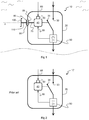
- Figure 2 discloses a prior art subsea circuit breaker 10'.
- the subsea circuit breaker 10' comprises a water tight circuit breaker enclosure 20 and two contacts 30, 35.
- the first contact 30 is stationary and is connected to an ingoing power line.
- the second contact 35 is movable and is connected to an outgoing power line.
- the ingoing power line is typically connected to a land based power grid (not illustrated), and the outgoing power line supplies one or more subsea electrical power consumers (item 210 in figure 4 ), such as a subsea power converter, with electricity.
- the movable contact 35 is manoeuvred/actuated by an electro-mechanical actuator 40 positioned within the circuit breaker enclosure 20, as is schematically illustrated by a dashed line between the electro-mechanical actuator 40 and the movable contact 35 arm.
- a protection element 50 is arranged to measure the current and/or the voltage on the outgoing power line.
- the protection element 50 is capable of detecting faults such as short circuits or overload situations on the outgoing power line. As is shown, the protection element 50 is coupled to the electro-mechanical actuator 40.
- the protection element 50 monitors the outgoing power line. In the event of a fault, the protection element 50 generates a fault signal 55 which is sent to the electro-mechanical actuator 40. Upon receipt of a fault signal 55, the electro-mechanical actuator 40 quickly opens the contacts 30, 35 by moving the movable contact 35 to the open position (the position which is illustrated in the figures). In this way, the outgoing electrical power is shut off and the connected electrical equipment, such as subsea electrical power consumers and cables, are protected from damage.
- the electro-mechanical actuator 40 is not only capable of manoeuvring the movable contact 35 upon receipt of a fault signal 55, but also in response to a command signal 65.
- a command signal 65 is typically generated by a topside control system (not shown).
- the command signal 65 is received by a command signal input interface 60 arranged within the circuit breaker enclosure 20.
- the command signal input interface 60 is formed by an input port 60 on the electro-mechanical actuator 40.
- figure 1 schematically discloses a subsea circuit breaker 10 installed underwater close to the seabed. All that has been explained above with reference to the prior art subsea circuit breaker 10' of figure 2 applies to figure 1 as well. The same reference numerals have therefore been used for the components of the prior art subsea circuit breaker 10' as for the components of the subsea circuit breaker 10 of the invention.
- the water is schematically illustrated by short wavy lines on the top left and right sides of the subsea circuit breaker 10, and the seabed is illustrated by a dashed wavy line below the subsea circuit breaker 10.
- the subsea circuit breaker 10 is submerged underwater and thereby completely surrounded by water and rests on the seabed. Even though not shown in the schematic figures of the present disclosure, the subsea circuit breaker 10 (or the subsea unit 200 of figure 4 ) is typically installed on subsea foundations or support structures.
- a so called mechanical override mechanism is illustrated on the left hand side of the subsea circuit breaker 10 in figure 1 .
- the contacts 30, 35 can be manoeuvred manually from the outside of the subsea circuit breaker 10.
- the contacts 30, 35 and the electro-mechanical actuator 40 are illustrated very schematically.
- the movable contact 35 may engage and disengage the stationary contact 30 while performing a pivoting movement (as illustrated), a rotating movement (not illustrated), or a linear movement (not illustrated).
- the movable and stationary contacts 30, 35 may also swap place such that the second contact 35 is connected to the ingoing power line.
- a contact free method of transferring torque from the outside of the circuit breaker enclosure 20 to the inside of the circuit breaker enclosure 20 is put to use.
- a magnetic force transfer means is arranged to transfer a mechanical force through the circuit breaker enclosure 20.
- the inner shaft 70 ends at an inner magnetic means 85.
- an outer magnetic means 80 is arranged facing the inner magnetic means 85.
- the subsea circuit breaker 10 can comprise a casing or similar which rotatively supports outer magnetic means 80.
- the outer magnetic means 80 may not be comprised in the subsea circuit breaker 10, but may be an external element.
- the outer magnetic means 80 may form part of a separate "key" which can be brought to the subsea circuit breaker 10 in order to open or close the contacts.
- a magnetic transfer area 90 is located between the inner and outer magnetic means.
- the magnetic transfer area 90 is a part of the circuit breaker enclosure 20, and the purpose of the magnetic transfer area 90 is to ensure that the inner and outer magnetic means may cooperate without the circuit breaker enclosure 20 obstructing the magnetic interaction.
- the circuit breaker enclosure 20, apart from the magnetic transfer area 90, may be of a material which does not allow magnetic interaction through it such as a material which is attracted to permanent magnets.
- Suitable materials for the magnetic transfer area are especially aluminium ("aluminum” in US English), glass, copper, platinum and austenitic stainless steel. These materials have a relative magnetic permeability which is very close to 1 (the relative magnetic permeability of vacuum), which means that the materials have little effect on a magnetic field passing through them. In this disclosure, a relative magnetic permeability lower than 2 is defined as a low relative magnetic permeability.
- the outer magnetic means 80 is connected to a mechanical operation input interface 100 which is here illustrated as a handle 100 which is manoeuvrable for a diver.
- An optional outer shaft 100 is arranged between the mechanical operation input interface 100 and the outer magnetic means 80.
- the mechanical operation input interface 100 may be another kind of turning device 100 such as a valve wheel. Alternatively, the mechanical operation input interface 100 may be tool receiving recess.
- the mechanical operation input interface 100 may be manoeuvrable for a diver, with or without tools.
- the mechanical operation input interface 100 may be a remotely operated vehicle (ROV) interface.
- ROV remotely operated vehicle
- a diver or a ROV may operate the subsea circuit breaker 10 by turning the mechanical operation input interface 100 and thereby open or close the contacts 30, 35.
- the turning movement applied to the mechanical operation input interface 100 rotates the outer shaft 110 and the outer magnetic means 80.
- the magnetic interaction between the outer magnetic means 80 and the inner magnetic means 85 causes the inner magnetic means 85 to rotate in synchronisation with the outer magnetic means 80.
- the inner shaft 70 brings the turning movement to the electro-mechanical actuator 40 which in turn manoeuvres the movable contact 35.
- stirrer drives for use with pressure reactors or stirred autoclaves in the chemical and pharmaceutical industry. Such stirrer drives must be tight and are therefore provided with magnetic couplings.
- One product called “bmd 1200" is able to transfer a torque of 12 Nm and can withstand a pressure difference of 350 bar.
- the product “bmd 1200” may be put to use as the magnetic force transfer means of the present disclosure.
- a similar product, “bmd 5400” which is able to transfer a higher torque of 54 Nm but withstands a lower pressure difference of 200 bar, may be put to use.
- stirrer drives are optimised to transfer great rotary speeds, exceeding 1000 rpm.
- the stirrer drives could be modified to be able to transfer greater torques, but at lower rotational speeds.
- the modification or optimisation of the stirrer drives, enabling them to transfer higher torques which may be desired when used as magnetic force transfer means driving a circuit breaker in a subsea unit, is not the subject of the present disclosure.
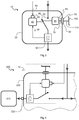
- subsea circuit breaker 10 comprises both an electro-mechanical actuator 40 and a mechanical actuator 45.
- the mechanical override mechanism is here realised without affecting the electro-mechanical actuator 40.
- the inner shaft 70 is connected to the mechanical actuator 45 and not to the electro-mechanical actuator 40.
- the movable contact 35 can be controlled by both the electro-mechanical actuator 40 and the mechanical actuator 45, as is illustrated by dashed lines between the movable contact 35 arm and both the electro-mechanical actuator 40 and the mechanical actuator 45, respectively.
- the mechanical override mechanism of figure 3 functions in the same manner as the one described with reference to figure 1 .
- the difference is only that the inner shaft 70 brings the turning movement to the mechanical actuator 45 (and not to the electro-mechanical actuator 40) which in turn manoeuvres the movable contact 35.
- the same reference numerals have therefore been used in figures 1 and 3 , apart from the reference numeral of the added mechanical actuator 45.
- the magnetic force transfer means is adapted to transfer a rotative force.
- the magnetic force transfer means is able to transfer a rotational movement or a torque.
- the magnetic force transfer means may alternatively be adapted to transfer a translative force, e.g. a linear force, in this connection a straight movement.
- the mechanical operation input interface may be a slider or a sliding mechanism (not shown) which is connected to the outer magnetic means 80.
- the inner magnetic means 85 would be adapted to travel along a straight line inside the subsea circuit breaker 10 and be arranged to open or close the contacts 30, 35 in response to a linear mechanical command operation from the outside of the circuit breaker enclosure 20.
- US6762662 B2 relates to a hermetically sealed electrical switch which is not suitable for subsea use.
- a magnetic force transfer means (items 140 and 160) which may transfer a translative force ( figure 1 ), or a rotative force (items 230 and 250 in figure 5).
- the subsea circuit breakers 10 shown in figures 1 and 3 are stand-alone or self-contained devices.
- the subsea circuit breakers 10 may be pressure proof or pressure compensated.
- the circuit breaker enclosure 20 may be pressure resistant in order to ensure that the pressure inside the circuit breaker enclosure 20 essentially equals atmospheric pressure, even when the subsea circuit breakers 10 is installed at a great depth.
- the circuit breaker enclosure 20 may be filled with a dielectric liquid and the subsea circuit breaker 10 may comprise or be connected to a pressure compensating device (not shown). Pressure compensating devices are known to the skilled person and therefore not described further here.
- a subsea circuit breaker 10 of the invention may also be incorporated as a part of a subsea unit 200.
- Figure 4 schematically illustrates a subsea circuit breaker 10 as the one of figure 1 as a part of a subsea unit 200.
- the subsea circuit breaker 10 is not a stand-alone or self-contained device and does not have an enclosure of its own.
- the circuit breaker enclosure forms a part of the subsea unit enclosure 220.
- the subsea unit 200 may be pressure proof or pressure compensated.
- the subsea unit 200 of figure 4 may comprise a plurality of subsea circuit breakers and also other internal equipment. Some of the subsea circuit breakers may comprise mechanical override mechanisms are described herein, and others not.
- the subsea unit 200 may be a subsea switchgear.
- the subsea unit 200 of figure 4 is connected to a subsea electrical power consumer 210.
- the subsea electrical power consumer 210 may be retrievable. Even in the event that the subsea unit 200 if not being supplied with electrical power, the mechanical override mechanism of the subsea circuit breaker 10 may be used to open or close the path of current to the subsea electrical power consumer 210.
Claims (15)
- Disjoncteur sous-marin (10) pour un système de distribution d'énergie électrique sous-marin, le disjoncteur (10) comprenant
une enveloppe étanche à l'eau (20) de disjoncteur,
des premier et deuxième contacts (30, 35) agencés à l'intérieur de l'enveloppe (20) de disjoncteur,
un actionneur électromécanique (40) agencé à l'intérieur de l'enveloppe (20) de disjoncteur et adapté à ouvrir les contacts (30, 35) en réponse à un signal de défaut (55) et à ouvrir ou fermer les contacts (30, 35) en réponse à un signal de consigne (65),
un élément de protection (50) agencé à l'intérieur de l'enveloppe (20) de disjoncteur et adapté à générer ledit signal de défaut (55),
une interface d'entrée (60) de signal de consigne agencée à l'intérieur de l'enveloppe (20) de disjoncteur, destinée à recevoir ledit signal de consigne (65),
caractérisé par
un moyen de transmission mécanique (70) agencé à l'intérieur de l'enveloppe (20) de disjoncteur et adapté à provoquer l'ouverture ou la fermeture des contacts (30, 35) en réponse à une opération de consigne mécanique depuis l'extérieur de l'enveloppe (20) de disjoncteur. - Disjoncteur sous-marin selon la revendication 1, comprenant un moyen de transfert de force magnétique (80, 85) adapté à transférer une force mécanique de ladite opération de consigne mécanique audit moyen de transmission mécanique (70).
- Disjoncteur sous-marin selon la revendication 2, dans lequel le moyen de transfert de force magnétique comprend un moyen magnétique extérieur (80), agencé à l'extérieur de l'enveloppe (20) de disjoncteur, et un moyen magnétique intérieur (85), agencé à l'intérieur de l'enveloppe (20) de disjoncteur.
- Disjoncteur sous-marin selon la revendication 3, dans lequel le moyen magnétique extérieur (80) et/ou le moyen magnétique intérieur (85) comprennent un aimant permanent.
- Disjoncteur sous-marin selon la revendication 3 ou 4, dans lequel l'enveloppe (20) de disjoncteur comprend une zone de transfert magnétique (90) située entre les moyens magnétiques extérieur et intérieur (80, 85), laquelle zone de transfert magnétique (90) présente une faible perméabilité magnétique relative, de sorte à essentiellement ne pas affecter l'interaction magnétique des moyens magnétiques extérieur et intérieur (80, 85).
- Disjoncteur sous-marin selon la revendication 5, dans lequel la perméabilité magnétique relative (µ/µ0) de la zone de transfert magnétique (90) est inférieure à 2.
- Disjoncteur sous-marin selon l'une quelconque des revendications 3 à 6, dans lequel le moyen magnétique extérieur (80) comprend un aimant permanent ou un matériau attiré par des aimants permanents, et le moyen magnétique intérieur (85) comprend un aimant permanent ou un matériau attiré par des aimants permanents, au moins un des moyens magnétiques intérieur et extérieur (80, 85) comprenant un aimant permanent, l'aimant permanent ou le matériau attiré par des aimants permanents des moyens magnétiques intérieur et extérieur (80, 85) étant agencé à distance d'un axe commun (z) et étant rotatif autour dudit axe (z), de façon à permettre le transfert d'un couple autour de l'axe (z) de l'extérieur de l'enveloppe (20) de disjoncteur vers l'intérieur de l'enveloppe (20) de disjoncteur.
- Disjoncteur sous-marin selon l'une quelconque des revendications 2 à 7, comprenant une interface d'entrée (100) d'opération mécanique destinée à recevoir ladite opération de consigne mécanique, ladite interface d'entrée (100) d'opération mécanique étant reliée au moyen de transmission mécanique (70) par l'intermédiaire du moyen de transfert de force magnétique (80, 85).
- Disjoncteur sous-marin selon l'une quelconque des revendications précédentes, dans lequel le moyen de transmission mécanique (70) est relié mécaniquement à l'actionneur électromécanique (40).
- Disjoncteur sous-marin selon l'une quelconque des revendications 1 à 9, comprenant un actionneur mécanique (45) distinct de l'actionneur électromécanique (40), le moyen de transmission mécanique (70) étant relié mécaniquement audit actionneur mécanique (45), lequel actionneur mécanique (45) est adapté à ouvrir ou fermer les contacts (30, 35) en réponse à une opération de consigne mécanique de l'extérieur de l'enveloppe (20) de disjoncteur.
- Disjoncteur sous-marin selon la revendication 9 ou 10, dans lequel l'actionneur électromécanique (40) ou l'actionneur mécanique (45) comprend deux positions d'extrémité, la première position d'extrémité étant une position dans laquelle les contacts (30, 35) sont ouverts et la deuxième position d'extrémité étant une position dans laquelle les contacts (30, 35) sont fermés.
- Disjoncteur sous-marin selon l'une quelconque des revendications précédentes, dans lequel l'enveloppe (20) de disjoncteur est résistante à la pression et adaptée ainsi à garantir que la pression à l'intérieur de l'enveloppe (20) de disjoncteur soit essentiellement égale à la pression atmosphérique, également lorsque le disjoncteur sous-marin est installé sous l'eau à une grande profondeur.
- Disjoncteur sous-marin selon l'une quelconque des revendications 1 à 11, dans lequel l'enveloppe (20) de disjoncteur est remplie d'un liquide diélectrique et le disjoncteur sous-marin (10) comprend un dispositif de compensation de pression, lequel dispositif de compensation de pression est adapté à garantir que la pression à l'intérieur de l'enveloppe (20) de disjoncteur soit essentiellement égale à la pression à l'extérieur de l'enveloppe (20) de disjoncteur.
- Unité sous-marine (200) pour un système de distribution d'énergie électrique sous-marin comprenant un disjoncteur sous-marin (10) selon l'une quelconque des revendications précédentes et une enveloppe étanche à l'eau (220) d'unité sous-marine enveloppant ledit disjoncteur sous-marin (10), l'enveloppe (20) de disjoncteur formant une partie de l'enveloppe (220) d'unité sous-marine.
- Système de distribution d'énergie électrique sous-marin comprenant un disjoncteur sous-marin (10) selon l'une quelconque des revendications 1 à 13 et/ou une unité sous-marine (200) selon la revendication 14.
Priority Applications (3)
| Application Number | Priority Date | Filing Date | Title |
|---|---|---|---|
| NO15170751A NO3101669T3 (fr) | 2015-06-05 | 2015-06-05 | |
| EP15170751.0A EP3101669B1 (fr) | 2015-06-05 | 2015-06-05 | Mécanisme de neutralisation d'actionneur pour disjoncteur sous-marin |
| US15/169,009 US10290453B2 (en) | 2015-06-05 | 2016-05-31 | Actuator override mechanism for subsea circuit breaker |
Applications Claiming Priority (1)
| Application Number | Priority Date | Filing Date | Title |
|---|---|---|---|
| EP15170751.0A EP3101669B1 (fr) | 2015-06-05 | 2015-06-05 | Mécanisme de neutralisation d'actionneur pour disjoncteur sous-marin |
Publications (2)
| Publication Number | Publication Date |
|---|---|
| EP3101669A1 EP3101669A1 (fr) | 2016-12-07 |
| EP3101669B1 true EP3101669B1 (fr) | 2017-11-15 |
Family
ID=53284136
Family Applications (1)
| Application Number | Title | Priority Date | Filing Date |
|---|---|---|---|
| EP15170751.0A Active EP3101669B1 (fr) | 2015-06-05 | 2015-06-05 | Mécanisme de neutralisation d'actionneur pour disjoncteur sous-marin |
Country Status (3)
| Country | Link |
|---|---|
| US (1) | US10290453B2 (fr) |
| EP (1) | EP3101669B1 (fr) |
| NO (1) | NO3101669T3 (fr) |
Families Citing this family (1)
| Publication number | Priority date | Publication date | Assignee | Title |
|---|---|---|---|---|
| IT201800005373A1 (it) * | 2018-05-15 | 2019-11-15 | Dispositivo attuatore per il passaggio di stato di una apparecchiatura a controllo elettronico ad uso subacqueo e relativo sistema |
Family Cites Families (12)
| Publication number | Priority date | Publication date | Assignee | Title |
|---|---|---|---|---|
| US4647733A (en) * | 1985-07-29 | 1987-03-03 | Proximity Controls, Inc. | Adjustable ratio transmission switch |
| GB8715089D0 (en) | 1987-06-26 | 1987-08-05 | Birns Uk Ltd | Electrical switches |
| CN1232995C (zh) | 2001-10-24 | 2005-12-21 | 李文丰 | 密闭型电气开关总成 |
| NO321080B1 (no) * | 2004-11-04 | 2006-03-13 | Bennex As | Bryter for høy spenning og/eller strøm |
| NO325440B1 (no) * | 2006-07-05 | 2008-05-05 | Vetco Gray Scandinavia As | Undersjoisk innretning |
| CN201238003Y (zh) | 2008-01-16 | 2009-05-13 | 符泽森 | 磁控安全使用开关 |
| GB2463487A (en) * | 2008-09-15 | 2010-03-17 | Viper Subsea Ltd | Subsea protection device |
| US8749327B2 (en) * | 2008-09-18 | 2014-06-10 | General Electric Company | Circuit interrupter trip apparatus and method |
| TW201117252A (en) | 2009-11-06 | 2011-05-16 | Wen-Feng Li | Magnetism-controlled sealed electric switch assembly |
| US9276387B2 (en) * | 2011-06-21 | 2016-03-01 | Labinal, Llc | Sealed plug-in circuit breaker assembly |
| US8803640B2 (en) * | 2012-08-29 | 2014-08-12 | Carling Technologies, Inc. | Remote operated circuit breaker |
| AU2014401829A1 (en) * | 2014-07-25 | 2017-02-09 | Abb Schweiz Ag | Refill-container for replenishing and/or reconditioning an insulation fluid contained in an insulation space of an electrical apparatus |
-
2015
- 2015-06-05 NO NO15170751A patent/NO3101669T3/no unknown
- 2015-06-05 EP EP15170751.0A patent/EP3101669B1/fr active Active
-
2016
- 2016-05-31 US US15/169,009 patent/US10290453B2/en active Active
Non-Patent Citations (1)
| Title |
|---|
| None * |
Also Published As
| Publication number | Publication date |
|---|---|
| US10290453B2 (en) | 2019-05-14 |
| EP3101669A1 (fr) | 2016-12-07 |
| NO3101669T3 (fr) | 2018-04-14 |
| US20160358735A1 (en) | 2016-12-08 |
Similar Documents
| Publication | Publication Date | Title |
|---|---|---|
| EP2987213B1 (fr) | Dispositif et système sous-marin de distribution d'énergie | |
| US20020011580A1 (en) | Electric actuator | |
| CN106549361B (zh) | 一种船舶的轴发电机装置 | |
| US10374398B2 (en) | Subsea power distribution device and system | |
| EP3132462B1 (fr) | Appareillage de commutation sous-marin | |
| EP3101669B1 (fr) | Mécanisme de neutralisation d'actionneur pour disjoncteur sous-marin | |
| CN105122412A (zh) | 真空开关装置 | |
| JPS59158027A (ja) | 電気開閉器 | |
| JP2008091333A (ja) | 鎖錠機構を有する開閉装置 | |
| GB2420018A (en) | Switch for high voltage and/or current | |
| JP2016173960A (ja) | 接地開閉器付断路器及びスイッチギヤ | |
| US8988020B1 (en) | Motor operator system for a power switch with travel set with three positions for ground or double-throw type switch | |
| EP3482406B1 (fr) | Dispositif d'isolation supplémentaire permettant de faire fonctionner à distance un disjoncteur pour équipement électrique | |
| JP2008235223A (ja) | 断路器、誤操作防止部材 | |
| JP2016157592A (ja) | 接地断路器並びにそれを用いる開閉装置 | |
| GB2613845A (en) | Method and system for operating actuators | |
| KR101864647B1 (ko) | 부유식 해상 발전 플랜트의 송전 케이블 보호 설비 | |
| US20090050453A1 (en) | Explosion proof safety switch apparatus | |
| CN101718968A (zh) | 用于控制工程设备的电气控制系统和工程设备 | |
| CN105206463A (zh) | 一种用于110kV电网的防误接地隔离开关 | |
| NO160388B (no) | Elektrisk ventil med dreibart ventillegeme. |
Legal Events
| Date | Code | Title | Description |
|---|---|---|---|
| PUAI | Public reference made under article 153(3) epc to a published international application that has entered the european phase |
Free format text: ORIGINAL CODE: 0009012 |
|
| AK | Designated contracting states |
Kind code of ref document: A1 Designated state(s): AL AT BE BG CH CY CZ DE DK EE ES FI FR GB GR HR HU IE IS IT LI LT LU LV MC MK MT NL NO PL PT RO RS SE SI SK SM TR |
|
| AX | Request for extension of the european patent |
Extension state: BA ME |
|
| RAP1 | Party data changed (applicant data changed or rights of an application transferred) |
Owner name: ABB SCHWEIZ AG |
|
| 17P | Request for examination filed |
Effective date: 20170607 |
|
| RBV | Designated contracting states (corrected) |
Designated state(s): AL AT BE BG CH CY CZ DE DK EE ES FI FR GB GR HR HU IE IS IT LI LT LU LV MC MK MT NL NO PL PT RO RS SE SI SK SM TR |
|
| GRAP | Despatch of communication of intention to grant a patent |
Free format text: ORIGINAL CODE: EPIDOSNIGR1 |
|
| RIC1 | Information provided on ipc code assigned before grant |
Ipc: H01H 9/04 20060101ALN20170705BHEP Ipc: H01H 3/28 20060101ALN20170705BHEP Ipc: H02B 13/00 20060101ALI20170705BHEP Ipc: H01H 33/53 20060101ALI20170705BHEP Ipc: H01H 3/56 20060101AFI20170705BHEP |
|
| INTG | Intention to grant announced |
Effective date: 20170728 |
|
| GRAS | Grant fee paid |
Free format text: ORIGINAL CODE: EPIDOSNIGR3 |
|
| GRAA | (expected) grant |
Free format text: ORIGINAL CODE: 0009210 |
|
| STAA | Information on the status of an ep patent application or granted ep patent |
Free format text: STATUS: THE PATENT HAS BEEN GRANTED |
|
| AK | Designated contracting states |
Kind code of ref document: B1 Designated state(s): AL AT BE BG CH CY CZ DE DK EE ES FI FR GB GR HR HU IE IS IT LI LT LU LV MC MK MT NL NO PL PT RO RS SE SI SK SM TR |
|
| REG | Reference to a national code |
Ref country code: CH Ref legal event code: EP Ref country code: GB Ref legal event code: FG4D Ref country code: AT Ref legal event code: REF Ref document number: 947030 Country of ref document: AT Kind code of ref document: T Effective date: 20171115 |
|
| REG | Reference to a national code |
Ref country code: IE Ref legal event code: FG4D |
|
| REG | Reference to a national code |
Ref country code: DE Ref legal event code: R096 Ref document number: 602015005955 Country of ref document: DE |
|
| REG | Reference to a national code |
Ref country code: NL Ref legal event code: MP Effective date: 20171115 |
|
| REG | Reference to a national code |
Ref country code: LT Ref legal event code: MG4D |
|
| REG | Reference to a national code |
Ref country code: AT Ref legal event code: MK05 Ref document number: 947030 Country of ref document: AT Kind code of ref document: T Effective date: 20171115 |
|
| REG | Reference to a national code |
Ref country code: NO Ref legal event code: T2 Effective date: 20171115 |
|
| PG25 | Lapsed in a contracting state [announced via postgrant information from national office to epo] |
Ref country code: LT Free format text: LAPSE BECAUSE OF FAILURE TO SUBMIT A TRANSLATION OF THE DESCRIPTION OR TO PAY THE FEE WITHIN THE PRESCRIBED TIME-LIMIT Effective date: 20171115 Ref country code: ES Free format text: LAPSE BECAUSE OF FAILURE TO SUBMIT A TRANSLATION OF THE DESCRIPTION OR TO PAY THE FEE WITHIN THE PRESCRIBED TIME-LIMIT Effective date: 20171115 Ref country code: FI Free format text: LAPSE BECAUSE OF FAILURE TO SUBMIT A TRANSLATION OF THE DESCRIPTION OR TO PAY THE FEE WITHIN THE PRESCRIBED TIME-LIMIT Effective date: 20171115 Ref country code: NL Free format text: LAPSE BECAUSE OF FAILURE TO SUBMIT A TRANSLATION OF THE DESCRIPTION OR TO PAY THE FEE WITHIN THE PRESCRIBED TIME-LIMIT Effective date: 20171115 Ref country code: SE Free format text: LAPSE BECAUSE OF FAILURE TO SUBMIT A TRANSLATION OF THE DESCRIPTION OR TO PAY THE FEE WITHIN THE PRESCRIBED TIME-LIMIT Effective date: 20171115 |
|
| PG25 | Lapsed in a contracting state [announced via postgrant information from national office to epo] |
Ref country code: HR Free format text: LAPSE BECAUSE OF FAILURE TO SUBMIT A TRANSLATION OF THE DESCRIPTION OR TO PAY THE FEE WITHIN THE PRESCRIBED TIME-LIMIT Effective date: 20171115 Ref country code: RS Free format text: LAPSE BECAUSE OF FAILURE TO SUBMIT A TRANSLATION OF THE DESCRIPTION OR TO PAY THE FEE WITHIN THE PRESCRIBED TIME-LIMIT Effective date: 20171115 Ref country code: LV Free format text: LAPSE BECAUSE OF FAILURE TO SUBMIT A TRANSLATION OF THE DESCRIPTION OR TO PAY THE FEE WITHIN THE PRESCRIBED TIME-LIMIT Effective date: 20171115 Ref country code: GR Free format text: LAPSE BECAUSE OF FAILURE TO SUBMIT A TRANSLATION OF THE DESCRIPTION OR TO PAY THE FEE WITHIN THE PRESCRIBED TIME-LIMIT Effective date: 20180216 Ref country code: AT Free format text: LAPSE BECAUSE OF FAILURE TO SUBMIT A TRANSLATION OF THE DESCRIPTION OR TO PAY THE FEE WITHIN THE PRESCRIBED TIME-LIMIT Effective date: 20171115 Ref country code: BG Free format text: LAPSE BECAUSE OF FAILURE TO SUBMIT A TRANSLATION OF THE DESCRIPTION OR TO PAY THE FEE WITHIN THE PRESCRIBED TIME-LIMIT Effective date: 20180215 |
|
| REG | Reference to a national code |
Ref country code: FR Ref legal event code: PLFP Year of fee payment: 4 |
|
| PG25 | Lapsed in a contracting state [announced via postgrant information from national office to epo] |
Ref country code: CZ Free format text: LAPSE BECAUSE OF FAILURE TO SUBMIT A TRANSLATION OF THE DESCRIPTION OR TO PAY THE FEE WITHIN THE PRESCRIBED TIME-LIMIT Effective date: 20171115 Ref country code: SK Free format text: LAPSE BECAUSE OF FAILURE TO SUBMIT A TRANSLATION OF THE DESCRIPTION OR TO PAY THE FEE WITHIN THE PRESCRIBED TIME-LIMIT Effective date: 20171115 Ref country code: EE Free format text: LAPSE BECAUSE OF FAILURE TO SUBMIT A TRANSLATION OF THE DESCRIPTION OR TO PAY THE FEE WITHIN THE PRESCRIBED TIME-LIMIT Effective date: 20171115 Ref country code: CY Free format text: LAPSE BECAUSE OF FAILURE TO SUBMIT A TRANSLATION OF THE DESCRIPTION OR TO PAY THE FEE WITHIN THE PRESCRIBED TIME-LIMIT Effective date: 20171115 Ref country code: DK Free format text: LAPSE BECAUSE OF FAILURE TO SUBMIT A TRANSLATION OF THE DESCRIPTION OR TO PAY THE FEE WITHIN THE PRESCRIBED TIME-LIMIT Effective date: 20171115 |
|
| REG | Reference to a national code |
Ref country code: DE Ref legal event code: R097 Ref document number: 602015005955 Country of ref document: DE |
|
| PG25 | Lapsed in a contracting state [announced via postgrant information from national office to epo] |
Ref country code: SM Free format text: LAPSE BECAUSE OF FAILURE TO SUBMIT A TRANSLATION OF THE DESCRIPTION OR TO PAY THE FEE WITHIN THE PRESCRIBED TIME-LIMIT Effective date: 20171115 Ref country code: IT Free format text: LAPSE BECAUSE OF FAILURE TO SUBMIT A TRANSLATION OF THE DESCRIPTION OR TO PAY THE FEE WITHIN THE PRESCRIBED TIME-LIMIT Effective date: 20171115 Ref country code: PL Free format text: LAPSE BECAUSE OF FAILURE TO SUBMIT A TRANSLATION OF THE DESCRIPTION OR TO PAY THE FEE WITHIN THE PRESCRIBED TIME-LIMIT Effective date: 20171115 |
|
| PLBE | No opposition filed within time limit |
Free format text: ORIGINAL CODE: 0009261 |
|
| STAA | Information on the status of an ep patent application or granted ep patent |
Free format text: STATUS: NO OPPOSITION FILED WITHIN TIME LIMIT |
|
| 26N | No opposition filed |
Effective date: 20180817 |
|
| PG25 | Lapsed in a contracting state [announced via postgrant information from national office to epo] |
Ref country code: SI Free format text: LAPSE BECAUSE OF FAILURE TO SUBMIT A TRANSLATION OF THE DESCRIPTION OR TO PAY THE FEE WITHIN THE PRESCRIBED TIME-LIMIT Effective date: 20171115 |
|
| REG | Reference to a national code |
Ref country code: CH Ref legal event code: PL |
|
| REG | Reference to a national code |
Ref country code: BE Ref legal event code: MM Effective date: 20180630 |
|
| REG | Reference to a national code |
Ref country code: IE Ref legal event code: MM4A |
|
| PG25 | Lapsed in a contracting state [announced via postgrant information from national office to epo] |
Ref country code: LU Free format text: LAPSE BECAUSE OF NON-PAYMENT OF DUE FEES Effective date: 20180605 Ref country code: MC Free format text: LAPSE BECAUSE OF FAILURE TO SUBMIT A TRANSLATION OF THE DESCRIPTION OR TO PAY THE FEE WITHIN THE PRESCRIBED TIME-LIMIT Effective date: 20171115 |
|
| PG25 | Lapsed in a contracting state [announced via postgrant information from national office to epo] |
Ref country code: CH Free format text: LAPSE BECAUSE OF NON-PAYMENT OF DUE FEES Effective date: 20180630 Ref country code: LI Free format text: LAPSE BECAUSE OF NON-PAYMENT OF DUE FEES Effective date: 20180630 Ref country code: IE Free format text: LAPSE BECAUSE OF NON-PAYMENT OF DUE FEES Effective date: 20180605 |
|
| PG25 | Lapsed in a contracting state [announced via postgrant information from national office to epo] |
Ref country code: BE Free format text: LAPSE BECAUSE OF NON-PAYMENT OF DUE FEES Effective date: 20180630 |
|
| PG25 | Lapsed in a contracting state [announced via postgrant information from national office to epo] |
Ref country code: MT Free format text: LAPSE BECAUSE OF NON-PAYMENT OF DUE FEES Effective date: 20180605 |
|
| PG25 | Lapsed in a contracting state [announced via postgrant information from national office to epo] |
Ref country code: TR Free format text: LAPSE BECAUSE OF FAILURE TO SUBMIT A TRANSLATION OF THE DESCRIPTION OR TO PAY THE FEE WITHIN THE PRESCRIBED TIME-LIMIT Effective date: 20171115 |
|
| PG25 | Lapsed in a contracting state [announced via postgrant information from national office to epo] |
Ref country code: PT Free format text: LAPSE BECAUSE OF FAILURE TO SUBMIT A TRANSLATION OF THE DESCRIPTION OR TO PAY THE FEE WITHIN THE PRESCRIBED TIME-LIMIT Effective date: 20171115 |
|
| PG25 | Lapsed in a contracting state [announced via postgrant information from national office to epo] |
Ref country code: MK Free format text: LAPSE BECAUSE OF NON-PAYMENT OF DUE FEES Effective date: 20171115 Ref country code: HU Free format text: LAPSE BECAUSE OF FAILURE TO SUBMIT A TRANSLATION OF THE DESCRIPTION OR TO PAY THE FEE WITHIN THE PRESCRIBED TIME-LIMIT; INVALID AB INITIO Effective date: 20150605 Ref country code: RO Free format text: LAPSE BECAUSE OF FAILURE TO SUBMIT A TRANSLATION OF THE DESCRIPTION OR TO PAY THE FEE WITHIN THE PRESCRIBED TIME-LIMIT Effective date: 20171115 |
|
| PG25 | Lapsed in a contracting state [announced via postgrant information from national office to epo] |
Ref country code: AL Free format text: LAPSE BECAUSE OF FAILURE TO SUBMIT A TRANSLATION OF THE DESCRIPTION OR TO PAY THE FEE WITHIN THE PRESCRIBED TIME-LIMIT Effective date: 20171115 Ref country code: IS Free format text: LAPSE BECAUSE OF FAILURE TO SUBMIT A TRANSLATION OF THE DESCRIPTION OR TO PAY THE FEE WITHIN THE PRESCRIBED TIME-LIMIT Effective date: 20180315 |
|
| PGFP | Annual fee paid to national office [announced via postgrant information from national office to epo] |
Ref country code: NO Payment date: 20230622 Year of fee payment: 9 Ref country code: FR Payment date: 20230628 Year of fee payment: 9 Ref country code: DE Payment date: 20230620 Year of fee payment: 9 |
|
| PGFP | Annual fee paid to national office [announced via postgrant information from national office to epo] |
Ref country code: GB Payment date: 20230622 Year of fee payment: 9 |