EP3101355B1 - Entlüftungsöffnung - Google Patents
Entlüftungsöffnung Download PDFInfo
- Publication number
- EP3101355B1 EP3101355B1 EP15170741.1A EP15170741A EP3101355B1 EP 3101355 B1 EP3101355 B1 EP 3101355B1 EP 15170741 A EP15170741 A EP 15170741A EP 3101355 B1 EP3101355 B1 EP 3101355B1
- Authority
- EP
- European Patent Office
- Prior art keywords
- optionally
- cover unit
- engagement
- locking
- attachment member
- Prior art date
- Legal status (The legal status is an assumption and is not a legal conclusion. Google has not performed a legal analysis and makes no representation as to the accuracy of the status listed.)
- Active
Links
Images








Classifications
-
- F—MECHANICAL ENGINEERING; LIGHTING; HEATING; WEAPONS; BLASTING
- F24—HEATING; RANGES; VENTILATING
- F24F—AIR-CONDITIONING; AIR-HUMIDIFICATION; VENTILATION; USE OF AIR CURRENTS FOR SCREENING
- F24F7/00—Ventilation
-
- F—MECHANICAL ENGINEERING; LIGHTING; HEATING; WEAPONS; BLASTING
- F24—HEATING; RANGES; VENTILATING
- F24F—AIR-CONDITIONING; AIR-HUMIDIFICATION; VENTILATION; USE OF AIR CURRENTS FOR SCREENING
- F24F13/00—Details common to, or for air-conditioning, air-humidification, ventilation or use of air currents for screening
- F24F13/02—Ducting arrangements
-
- F—MECHANICAL ENGINEERING; LIGHTING; HEATING; WEAPONS; BLASTING
- F24—HEATING; RANGES; VENTILATING
- F24F—AIR-CONDITIONING; AIR-HUMIDIFICATION; VENTILATION; USE OF AIR CURRENTS FOR SCREENING
- F24F7/00—Ventilation
- F24F2007/0025—Ventilation using vent ports in a wall
Definitions
- the present invention relates to an air vent for ventilating an enclosed space within a building structure to an external environment, such as to the atmospheric environment external of a building structure, and in particular which allows for installation of the vent from within the building structure.
- vents exist for ventilating building structures, and which allow for installation from within the building structure.
- One such vent is disclosed in GB-A-2467109 , where the outer, peripheral sealing flange of the external cover tapers rearwardly, such that on installing the vent, by pushing though a channel, the sealing flange is deflected inwardly by the internal surface of the channel.
- GB-A-2464294 discloses an adjustable ventilation coupling for enabling air flow to/from a wall, ceiling or floor cavity of a structure, comprising adaptors arranged to engage in use with respective external and internal vents, and connectors which connect the adaptors to an air transfer duct so that the lateral spacing can be varied whilst maintaining the adaptors in a desired orientation.
- the present invention provides an air vent for providing ventilation through a bore in a building structure according to claim 1.
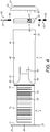
- the air vent comprises a first body 3, which is located to an internal side of a building structure, a second body 5, which is located to an external side of the building structure and is coupled to the first body 3 to provide a continuous duct which extends through the building structure, and a cover unit 7 which is movably disposed within the second body 5 between a first non-deployed position, as illustrated in Figure 1 , and a deployed position, as illustrated in Figure 2 .
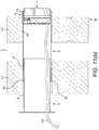
- the building structure is a cavity wall W, which comprises an inner leaf L1, an outer leaf L2 and a cavity C between the inner and outer leaves L1, L2, as illustrated in Figures 11(a) to (f) , with the vent being adapted to be inserted through a bore B formed in the wall W.
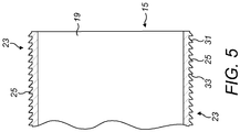
- the first body 3 comprises a tubular member 15 having inner and outer ends 17, 19, in this embodiment having circular section, which extends into the bore B of the wall W, and a fixing member 21 at the inner end 17 of the tubular member 15, which provides for fixing of the first body 3 to the wall W.
- the tubular member 15 includes at least one engagement section 23 which provides for engagement with a counterpart engagement section 53 on the second body 5, as will be described in more detail hereinbelow.
- the at least one engagement section 23 extends around only part of the periphery of the tubular member 15, whereby the first and second bodies 3, 5, when in a first angular relation, provide for inter-engagement of the engagement sections 23, 53, and, when in a second angular relation, provide for dis-engagement of the engagement sections 23, 53, such that the first and second bodies 3, 5 can be freely moved axially in relation to one another.
- the tubular member 15 includes first and second engagement sections 23 which extend around only part of the periphery of the tubular member 15, here in first and second segments which are arranged in spaced annular relation.
- first and second engagement sections 23 are arranged in opposite, symmetrical relation, here each extending over a 90 degree arc of the peripheral surface of the tubular member 15.
- the at least one engagement section 23 comprises a plurality of engagement elements 25 which are arranged in spaced relation along the axial length of the tubular member 15 and provide for engagement with counterpart engagement elements 53 on the second body 5, as will be described in more detail hereinbelow.
- the engagement elements 25 each comprise a tooth or detent, here having a first, tapered forward surface 31, which allows the counterpart engagement elements 55 of the second body 5 to pass relatively easily thereover when the first and second bodies 3, 5 are moved in axial relation to collapse the same, and a second, locking surface 33, against which the counterpart engagement elements 55 of the second body 5 are locked to prevent the first body 3 being withdrawn from the second body 5; with such withdrawal requiring rotation of the first body 3 in relation to the second body 5, as described hereinabove.
- the fixing member 21 comprises an outwardly-extending flange 37, which is fixed against an inner surface, here by fixing screws at apertures 39.
- the second body 5 comprises a tubular member 45 having inner and outer ends 47, 49, in this embodiment having circular section, which extends into the bore B of the wall W and slideably receives the first body 3 therewithin, and an attachment member 51 at the outer end 49 of the tubular member 45, which provides for attachment of the vent cover assembly 7.
- the tubular member 45 includes at least one engagement section 53 which provides for engagement with the at least one engagement section 23 on the first body 3, in order to allow the first and second bodies 3, 5 to be locked in axial relation.
- the at least one engagement section 53 extends around only part of the periphery of the tubular member 45, whereby the first and second bodies 3, 5, when in a first angular relation, provide for inter-engagement of the engagement sections 23, 53, and, when in a second angular relation, provide for dis-engagement of the engagement sections 23, 53, such that the body sections 3, 5 can be freely moved axially in relation to one another.
- the tubular member 45 includes first and second engagement sections 53 which extend around only part of the periphery of the tubular member 45, here in first and second segments which are arranged in spaced annular relation.
- first and second engagement sections 53 are arranged in opposed, symmetrical relation, here each extending over a 45 degree arc of the peripheral surface of the tubular member 45.
- the at least one engagement section 53 comprises at least one engagement element 55 which provide for engagement with counterpart engagement elements 25 on the first body 3.
- the at least one engagement section 53 comprises a plurality of engagement elements 55 which are arranged in spaced relation along the axial length of the tubular member 45 and provide for engagement with counterpart engagement elements 25 on the first body 3.
- the engagement elements 55 each comprise a tooth or detent, here having a first, tapered forward surface 61, which allows the counterpart engagement elements 25 of the first body 3 to pass relatively easily thereover when the first and second bodies 3, 5 are moved in axial relation to collapse the same, and a second, locking surface 63, against which the counterpart engagement elements 25 of the first body 3 are locked to prevent the first body 3 being withdrawn from the second body 5; with such withdrawal requiring rotation of the first body 3 in relation to the second body 5, as described hereinabove.
- the at least one engagement section 53 is resiliently coupled to a main section of the tubular body 45, here by forming the at least one engagement section 53 as a tab, such as to facilitate sliding of the counterpart engagement elements 25, 55 thereover when the first and second bodies 3, 5 are moved in axial relation to collapse the same.
- tubular member 45 includes projections 65 at the one, inner end 47 thereof which can be cut in accordance with the width of the wall W, such that the length of the second body 5 can be made shorter than the width of the wall W but such that the one, inner end of the second body 5 extends into the inner leaf L1 across the cavity C,
- the attachment member 51 defines a recess 71 in which the vent cover assembly 7 is slideably disposed between a first, withdrawn or non-deployed position, as illustrated in Figure 1 , and a second, deployed position, as illustrated in Figure 2 .
- the attachment member 51 includes a stop 73, here in the form of an annular flange, against which the vent cover assembly 7 is disposed in the withdrawn or non-deployed position.
- the attachment member 51 includes at least one aperture 75 therein, which receives and through which extends the locking element 85 of at least one locking member 83 of the cover unit 7 when the cover unit 7 is moved to the deployed position.
- the attachment member 51 includes at least one guide 77, here in the form of a path or track, which receives the at least one locking member 83 of the cover unit 7 and acts to guide the locking element 85 of the at least one locking member 83 to the at least one aperture 75.
- the attachment member 51 includes at least one detent 79 which is located outwardly of the at least one aperture 75, and is configured to prevent the locking element 85 of the at least one locking member 83 being moved outwardly beyond the at least one aperture 75.
- the attachment member 51 includes a plurality of locking apertures 75 therein, here arranged in spaced annular relation, through which extend the locking elements 85 of a plurality of locking members 83 of the cover unit 7 when the cover unit 7 is moved to the deployed position.
- the attachment member 51 includes a plurality of guides 77, which receive the locking members 83 of the cover unit 7 and act to guide the locking elements 85 of the locking members 83 to the apertures 75.
- the attachment member 51 includes a plurality of detents 77 which are located outwardly of the respective apertures 75.
- the cover unit 7 comprises a body member 81 which is slideably disposed within the attachment member 51 of the second body 5, and at least one locking member 83 which is configured to extend through the at least one aperture 75 in the attachment member 51 when the cover unit 7 is in the deployed position.
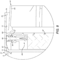
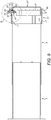
- the at least one locking member 83 comprises a locking element 85 which is radially-outwardly biased to the body member 81, such that the locking element 85 is disposed in a radially-inward position when the cover unit 7 is in the non-deployed position, as illustrated in Figures 7 and 8 , with the distal end of the locking element 85 being located in the at least one guide 77 in the attachment member 51, and disposed in a radially-outward position when the cover unit 7 is in the deployed position, as illustrated in Figures 9 and 10 , with the locking element 85 extending through the at least one aperture 75 in the attachment member 51 and locking the cover unit 7 in the deployed position.
- the body member 81 includes at least one recess 87 at the periphery thereof, and the at least one locking member 83 includes a biasing element 89, here a compression spring, which is disposed within the at least one recess 87 and acts to bias the locking element 85 radially outwardly, such as to cause the locking element 85 to extend through the respective aperture 75 in the attachment member 51 when the cover unit 7 is in the deployed position.
- a biasing element 89 here a compression spring
- the cover unit 7 includes a plurality of locking members 83, which are configured to extend through respective ones of the plurality of the apertures 75 in the attachment member 51 of the second body 5, such as to lock the cover unit 7 in the deployed position.
- the cover unit 7 further comprises an annular seal 91 which is configured to provide a weathertight seal about the periphery of the bore B formed in the wall W.
- the seal 91 comprises a support element 93 which is fixed to the body member 81, and a seal element 95, which is configurable between a withdrawn or non-deployed configuration, as illustrated in Figures 7 and 8 , in which the seal element 95 is disposed radially inwardly of the attachment member 51 of the second body 5, and a deployed configuration, as illustrated in Figures 9 and 10 , in which the seal element 95 extends radially outwardly of the attachment member 51 of the second body 5, such that the seal element 95 is engageable with an outer surface of the wall W about the bore B formed in the wall W.
- the seal element 95 is formed of a resilient material and defines a frusto-conical section which tapers outwardly and rearwardly from a forward edge thereof when in the deployed configuration, as illustrated in Figures 9 and 10 , and is folded forwardly and inwardly when in the non-deployed configuration, as illustrated in Figures 7 and 8 .
- the seal member 91 is formed of a rubber or elastomer, here a thermoplastic elastomer.
- the body member 81 provides a grille 97, here a slatted grille, through which passes an air flow.
- a bore B of predetermined diameter is formed in the wall W, here extending through the inner and outer leaves L1, L2.
- the operative measures the thickness of the wall W in order to ensure that the length of the second body 5, when fitted, is such that the proximal end 47 of the second body 5 will be located within the inner leaf L1. If the second body 5 needs to be shortened, the projections 65 at the proximal end 47 of the second body 5 are cut accordingly.
- a holding tool 101 is attached to the cover unit 7, and the air vent, with the cover unit 7 in the withdrawn or non-deployed position and the first engagement sections 23, 53 of the first and second bodies 3, 5 disengaged, is inserted into the bore B in the wall W, such that the attachment member 51 at the distal end 49 of the second body 5 extends beyond the outer surface of the wall W. In this position, the apertures 75 in the attachment member 51 are located externally of the wall W.
- the holding tool 101 is a line, such as a string line.
- the cover unit 7 is moved from the withdrawn position to the deployed position, in which the locking elements 85 of the locking members 83 are biased to extend through the apertures 75 in the attachment member 51 and the seal element 95 of the seal member 91 adopts the deployed position, providing a frusto-conical element which is outwardly and rearwardly flared.
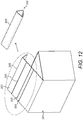
- the pusher tool 103 is a rod, here formed by part of the packaging 201 in which the air vent is supplied.
- the packaging 201 is configured such that part of the packaging 201, here part of the lid 203, is detachable along a separation line 204, and pre-configured with fold lines 205 to form the pusher tool 103 by folding.
- packaging 201 is cardboard packaging.
- the holding and pusher tools 101, 103 could be provided by a single tool which provides a rod and an engagement element at the distal end.
- the holding tool 101 is pulled rearwardly in order to draw the cover unit 7 and the body members 3, 5 attached thereto rearwardly or inwardly.
- the locking elements 85 which project radially outwardly of the attachment member 51 engage the outer surface of the wall W when the cover unit 7 is drawn rearwardly, thereby fixing the cover unit 7 in relation to the wall W, and, in this position, the seal element 95 of the seal member 91 engages the outer surface of the wall W, such as to provide a weathertight seal around the aperture as defined by the bore B in the wall W.
- the first body 3 is rotated in relation to the second body 5 such that the first engagement sections 23, 53 of the first and second bodies 3, 5 are engaged, and moved axially into the bore B in the wall W until the flange 37 as provided by the stop 21 engages the inner surface of the wall W.
- the air vent is held in position by engagement of the flange 37 against the inner wall and the locking elements 85 against the outer surface of the wall W, and the bodies 3, 5 are held in relative position by the respective engagement sections 23, 53 thereof, which cannot be released until the first body 3 is rotated in relation to the second body 5.
- the first body 3 is fixed to the wall using fixings 107 which pass though the apertures 39 in the flange 37.
Landscapes
- Engineering & Computer Science (AREA)
- Chemical & Material Sciences (AREA)
- Combustion & Propulsion (AREA)
- Mechanical Engineering (AREA)
- General Engineering & Computer Science (AREA)
- Ventilation (AREA)
Claims (14)
- Entlüfter zur Bereitstellung einer Belüftung durch eine Bohrung (B) in einer Gebäudestruktur, worin der Entlüfter umfasst, einen ersten Körper (3), der an einer ersten, inneren Seite der Gebäudestruktur angeordnet werden kann, einen zweiten Körper (5), der an einer zweiten, äußeren Seite der Gebäudestruktur angeordnet werden kann und mit dem ersten Körper (3) gekoppelt ist, um eine Leitung bereit zu stellen, die sich durch die Gebäudestruktur erstreckt, und eine Abdeckeinheit (7);
dadurch gekennzeichnet, dass die Abdeckeinheit (7) in dem zweiten Körper (5) zwischen einer ersten Nicht-Benutzungs-Position, bei der die Abdeckeinheit (7) in den zweiten Körper (5) zurückgefahren ist, zu einer zweiten, Benutzungs-Position, bei der die Abdeckeinheit (7) aus dem zweiten Körper (5) ausgefahren ist, bewegbar angeordnet ist. - Entlüfter nach Anspruch 1, worin der erste und zweite Körper (3, 5) axial gleitend angeordnet sind und jeder mindestens einen Eingriffsbereich (23, 53) umfasst, der bei jeweiligem Eingriff verhindert, dass sich der erste und zweite Körper (3, 5) axial erstreckt, wahlweise worin sich der mindestens eine Eingriffsbereich (23, 53) auf jedem des ersten und zweiten Körpers (3, 5) um nur einen Teil der Umfangsoberfläche davon erstreckt, wobei der erste und zweite Körper (3, 5) in einer ersten Winkelstellung einen gegenseitigen Eingriff der Eingriffsbereiche (23, 53) liefert, und in einer zweiten Winkelstellung ein Lösen der Eingriffsbereiche (23, 53) liefert, so dass sich der erste und zweite Körper (3, 5) relativ zueinander axial erstrecken oder zusammenschieben, wahlweise worin der erste Körper (3) einen ersten und zweiten Eingriffsbereich (23) umfasst, die als erste und zweite Segmente ringförmig beanstandet angeordnet sind, wahlweise worin die ersten und zweiten Segmente symmetrisch abgewandt voneinander angeordnet sind und sich jeweils wahlweise über weniger als einen 120 Grad Bogen der Umfangsoberfläche erstrecken, wahlweise worin der zweite Körper (5) erste und zweite Eingriffsbereiche (53) umfasst, die als erste und zweite Segmente ringförmig beabstandet angeordnet sind, wahlweise worin das erste und zweite Segment abgewandt symmetrisch angeordnet sind und sich jeweils wahlweise über weniger als einen 60 Grad Bogen der Umfangs-Oberfläche erstrecken, wahlweise worin der mindestens eine Eingriffsbereich (23) auf dem ersten Körper (3) mehrere Eingriffselements (25) umfasst, die axial beabstandet angeordnet sind, und worin der mindestens eine Eingriffsbereich (53) auf dem zweiten Körper (5) mindestens ein Eingriffselement (55) umfasst, das mit jeweils einem der Eingriffselemente (25) auf dem ersten Körper (3) eingreift, wahlweise worin die Eingriffselemente (25) auf dem ersten Körper (3) eine erste sich verjüngende vordere Oberfläche (31) aufweist, die ermöglicht, dass das mindestens eine Eingriffselement (55) auf dem zweiten Körper (5) darüber gleitet, wenn der erste und zweite Körper (3, 5) axial bewegt werden, um diese ineinander zu schieben, und eine zweite, Sperrfläche (33), gegen die das mindestens eine Eingriffselement (55) auf dem zweiten Körper (5) gesperrt wird, um zu verhindern, dass der erste Körper (3) aus dem zweiten Körper (5) gezogen wird.
- Entlüfter nach Anspruch 1 oder 2, worin der mindestens eine Eingriffsbereich (23, 53) von mindestens einem des ersten und zweiten Körpers (3, 5) federnd gekoppelt ist, um ein Gleiten des Gegen-Eingriffsbereichs (23, 53) darüber zu erleichtern, wenn der erste und zweite Körper (3, 5) axial bewegt werden, um diese ineinander zu schieben.
- Entlüfter nach einem der Ansprüche 1 bis 3, worin der erste Körper (3) ein röhrenförmiges Element (15) mit einem ersten und zweiten Ende (17, 19) umfasst, das sich in die Bohrung (B) der Gebäudestruktur erstreckt, wahlweise worin der erste Körper (3) weiter ein Fixierungselement (21) an einem ersten inneren Ende (17) des röhrenförmigen Elements (15) umfasst, das einen Eingriff mit der ersten Seite der Gebäudestruktur liefert, wahlweise worin das Fixierungselement (21) eine sich nach außen erstreckende Flansch (37) umfasst, die an die erste Seite der Gebäudestruktur befestigt werden kann.
- Entlüfter nach einem der Ansprüche 1 bis 4, worin der zweite Körper (5) ein röhrenförmiges Element (45) mit einem ersten und zweiten Ende (47, 49) umfasst, das sich in die Bohrung (B) der Gebäudestruktur erstreckt, wahlweise worin das röhrenförmige Element (45) des zweiten Körpers (5) Vorsprünge (65) an dem ersten inneren Ende (47) davon umfasst, die gemäß einer Weite der Gebäudestruktur geschnitten werden kann.
- Entlüfter nach Anspruch 5, worin der zweite Körper (5) weiter ein Anbringungselement (51) an dem zweiten, äußeren Ende (49) des röhrenförmigen Elements (45) davon umfasst, das eine Anbringung der Abdeckeinheit (7) liefert, wahlweise worin das Anbringungselement (51) eine Vertiefung (71) definiert, in der die Abdeckeinheit (7) gleitend zwischen der Nicht-Benutzungs-Position und der Benutzungs-Position vorgesehen ist, wahlweise worin das Anbringungselement (51) einen Stopper (73) zum Eingriff mit der Abdeckeinheit (7), wenn in der Nicht-Benutzungsposition, umfasst.
- Entlüfter nach einem der Ansprüche 1 bis 6, worin das Anbringungselement (51) mindestens eine Öffnung oder Vertiefung (75) umfasst, und worin die Abdeckeinheit (7) ein Körper-Element (81) aufweist, das an dem zweiten Körper (5) gleitend vorgesehen ist, und mindestens ein Sperrelement (83), das ein Sperr-Teil (85) umfasst, welches ausgestaltet ist, mit der mindestens einen Öffnung oder Vertiefung (75) in dem Anbringungselement (51) in Eingriff zu kommen, wenn die Abdeckeinheit (7) in der Benutzungs-Position ist, um die Abdeckeinheit (7) in der Benutzungs-Position an dem Anbringungselement (51) zu sperren, wahlweise worin die mindestens eine Öffnung oder Vertiefung (75) in dem Anbringungselement (51) einer Durchgangsöffnung ist, so dass sich das Sperr-Teil (85) radial nach außen durch die Durchgangsöffnung erstreckt, wenn die Abdeckeinheit (7) in der Benutzungs-Position ist.
- Entlüfter nach Anspruch 7, worin das Sperr-Teil (85) des mindestens einen Sperrelements (83) radial nach außen vorgespannt ist, so dass das Sperr-Teil (85) in einer radial nach innen Position angeordnet ist, wenn die Abdeckeinheit (7) in der Nicht-Benutzungs-Position ist, und in einer radial nach außen gerichteten Position ist, wenn die Abdeckeinheit (7) in der Benutzungs-Position ist.
- Entlüfter nach Anspruch 8, worin das Körper-Element (81) der Abdeckeinheit (7) mindestens eine Vertiefung (87) an einem Umfang davon umfasst, worin das mindestens eine Sperrelement (83) ein Spannelement (89) umfasst, das in der mindestens einen Vertiefung (87) des Körper-Elements (81) der Abdeckeinheit (7) vorgesehen ist und das Sperr-Teil (85) radial nach außen spannt.
- Entlüfter nach einem der Ansprüche 7 bis 9, worin das Anbringungselement (51) mindestens eine Führung (77) umfasst, wahlweise in der Form eines Pfads oder Wegs, der das mindestens eine Sperrelement (83) aufnimmt und das Sperr-Teil (85) des mindestens einen Sperrelements (83) zu der mindestens einen Öffnung oder Vertiefung (75) des Anbringungselements (51) führt.
- Entlüfter nach einem der Ansprüche 7 bis 10, worin das Anbringungselement (51) mindestens einen Stopper (73) umfasst, der außerhalb der mindestens einen Öffnung oder Vertiefung (75) davon angeordnet und ausgestaltet ist, zu verhindern, dass das Sperr-Teil (85) des mindestens einen Sperrelements (83) nach außen über die mindestens eine Öffnung oder Vertiefung (75) des Anbringungselements (51) bewegt wird.
- Entlüfter nach einem der Ansprüche 7 bis 11, worin das Anbringungselement (51) mehrere Öffnungen oder Vertiefungen (75) aufweist, und worin die Abdeckeinheit (7) mehrere Sperrelemente (83) umfasst, worin die Sperr-Teile (85) der Sperrelemente (83) ausgestaltet sind, mit jeweils einer der Öffnungen oder Vertiefungen (75) des Anbringungselements (51) in Eingriff zu kommen, wahlweise worin das Anbringungselement (51) mehrere Führungen (77) aufweist, die jeweils eines der Sperrelemente (83) aufnimmt und die Sperr-Teile (85) der Sperrelemente (83) zu den Öffnungen oder Vertiefungen (75) des Anbringungselements (51) führt, wahlweise worin das Anbringungselement (51) mehrere Stopper (73) umfasst, die außerhalb der jeweiligen Öffnungen oder Vertiefungen (75) davon angeordnet sind.
- Entlüfter nach einem der Ansprüche 7 bis 12, worin das Körper-Element (81) der Abdeckeinheit (7) gleitend in dem Anbringungselement (51) angeordnet ist und das mindestens eine Sperrelement (83) trägt.
- Entlüfter nach einem der Ansprüche 7 bis 13, worin die Abdeckeinheit (7) weiter ein ringförmiges Dicht-Teil (91) umfasst, das an das Körper-Element (81) davon angebracht und ausgestaltet ist, eine Wetter-dichte Dichtung um den Umfang der Bohrung (B) in der Gebäudestruktur zu liefern, wenn die Abdeckeinheit (7) in der Benutzungs-Position ist, wahlweise worin das Dicht-Teil (91) ein Trägerelement (93) umfasst, das an dem Körper-Element (81) der Abdeckeinheit (7) angebracht ist, und ein Dichtungselement (95), das zwischen einer zurückgezogenen oder Nicht-Benutzungs-Konfiguration, in der das Dichtungselement (95) radial in dem Anbringungselement (51) vorgesehen ist, und einer Benutzungs-Konfiguration, in der sich das Dichtungselement (95) radial außerhalb des Anbringungselements (51) erstreckt, einstellbar ist, so dass das Dichtungselement (95) mit einer äußeren Oberfläche der Gebäudestruktur um die Bohrung (B) in der Gebäudestruktur in Eingriff gebracht werden kann, wahlweise worin das Dichtungselement (95) aus einem elastischen Material gebildet ist und einen abgestumpfte Bereich ausbildet, der sich in der Benutzungs-Konfiguration nach außen verjüngt und von einer vorderen Kante davon nach hinten, und in der Nicht-Benutzungs-Konfiguration nach vorne und nach innen gefaltet ist, wahlweise worin das Dicht-Teil (91) aus einem Gummi oder Elastomer gebildet ist, wahlweise einem thermoplastischen Elastomer, wahlweise worin das Körper-Element (81) der Abdeckeinheit (7) ein Gitter liefert, wahlweise, wahlweise ein Latten-Gitter, durch das bei Verwendung ein Luftstrom gelangt.
Priority Applications (2)
| Application Number | Priority Date | Filing Date | Title |
|---|---|---|---|
| EP15170741.1A EP3101355B1 (de) | 2015-06-04 | 2015-06-04 | Entlüftungsöffnung |
| PCT/EP2016/062720 WO2016193475A1 (en) | 2015-06-04 | 2016-06-03 | Air vent |
Applications Claiming Priority (1)
| Application Number | Priority Date | Filing Date | Title |
|---|---|---|---|
| EP15170741.1A EP3101355B1 (de) | 2015-06-04 | 2015-06-04 | Entlüftungsöffnung |
Publications (2)
| Publication Number | Publication Date |
|---|---|
| EP3101355A1 EP3101355A1 (de) | 2016-12-07 |
| EP3101355B1 true EP3101355B1 (de) | 2020-09-23 |
Family
ID=53365869
Family Applications (1)
| Application Number | Title | Priority Date | Filing Date |
|---|---|---|---|
| EP15170741.1A Active EP3101355B1 (de) | 2015-06-04 | 2015-06-04 | Entlüftungsöffnung |
Country Status (2)
| Country | Link |
|---|---|
| EP (1) | EP3101355B1 (de) |
| WO (1) | WO2016193475A1 (de) |
Families Citing this family (3)
| Publication number | Priority date | Publication date | Assignee | Title |
|---|---|---|---|---|
| DE102017005624B4 (de) * | 2017-06-14 | 2022-08-11 | Gert Bartholomäus | Mauerdurchführungsrohr |
| FR3111182B1 (fr) * | 2020-06-08 | 2022-06-17 | Brain Soda Company Ltd | Dispositif de ventilation pour le refroidissement intérieur d’un habitat |
| US20240255172A1 (en) * | 2023-01-31 | 2024-08-01 | Yisrael Rosenberg | Louver vent / dryer vent system and methods of use |
Family Cites Families (5)
| Publication number | Priority date | Publication date | Assignee | Title |
|---|---|---|---|---|
| JPS55179276U (de) * | 1979-06-12 | 1980-12-23 | ||
| DE2945749C2 (de) * | 1979-11-13 | 1982-03-18 | Heinz 4390 Gladbeck Kiparski | Wandanschlußstück |
| GB2283312A (en) * | 1993-10-28 | 1995-05-03 | Baxi Partnership Ltd | A wall-mounted ventilator |
| GB2467109B (en) | 2008-07-04 | 2012-09-12 | Peter Arezina | Improvements to ventilation duct installation |
| GB2464294A (en) * | 2008-10-09 | 2010-04-14 | Paul Iain Jerram | Adjustable ventilation coupling for wall, ceiling or floor cavities |
-
2015
- 2015-06-04 EP EP15170741.1A patent/EP3101355B1/de active Active
-
2016
- 2016-06-03 WO PCT/EP2016/062720 patent/WO2016193475A1/en not_active Ceased
Non-Patent Citations (1)
| Title |
|---|
| None * |
Also Published As
| Publication number | Publication date |
|---|---|
| WO2016193475A1 (en) | 2016-12-08 |
| EP3101355A1 (de) | 2016-12-07 |
Similar Documents
| Publication | Publication Date | Title |
|---|---|---|
| US8651788B1 (en) | Variable-length, adjustable spacer | |
| US10309461B2 (en) | Torque transfer coupler with anti-slip feature for roller blind drive mechanism | |
| EP3101355A1 (de) | Entlüftungsöffnung | |
| ES2911023T3 (es) | Mecanismo de bloqueo para cuerpo tubular | |
| US20090028659A1 (en) | Clip | |
| EP2216487B1 (de) | Längenverstellbares Passstück für Rollosysteme | |
| US20150376941A1 (en) | Covering for an architectural opening | |
| EP2229245B1 (de) | Anordnung, lüftungsarm, lüftungssystem | |
| USD802113S1 (en) | Axial fan | |
| KR20140085293A (ko) | 의료용 튜브 및 그를 구비하는 가소성 가변기구 | |
| US20110101152A1 (en) | Roll Sleeve | |
| US12140254B2 (en) | Adaptive retainer | |
| TWI674364B (zh) | 用於將連接器安裝至面板之緊固件、連接器總成及將連接器安裝至面板之方法 | |
| US10900280B2 (en) | Architectural structure covering having a speed regulating assembly | |
| US20180318870A1 (en) | Caulking gun | |
| US11331436B2 (en) | Medicament container holder for a medicament delivery device and method of assembling a medicament delivery device | |
| TW202348887A (zh) | 用於簾幕之管件的馬達以及用於嚙合管件之內部表面的一組可轉接的插塞之總成 | |
| CN103362912A (zh) | 伸缩结构、套筒及插接杆 | |
| US20140207196A1 (en) | Limited Collapse Surgical Screws | |
| US20140265158A1 (en) | Drain Seal | |
| JP2009264516A (ja) | 配線・配管材用のスリーブ | |
| CN202140005U (zh) | 一种用于遮帘系统的长度可调的装置 | |
| WO2011033052A2 (de) | System und verfahren zur abdichtung einer leerdose in einer wand | |
| CN105896424A (zh) | 一种预埋盒安装调节结构 | |
| DE102019212355A1 (de) | Teleskopierbarer Luftkanal |
Legal Events
| Date | Code | Title | Description |
|---|---|---|---|
| PUAI | Public reference made under article 153(3) epc to a published international application that has entered the european phase |
Free format text: ORIGINAL CODE: 0009012 |
|
| STAA | Information on the status of an ep patent application or granted ep patent |
Free format text: STATUS: THE APPLICATION HAS BEEN PUBLISHED |
|
| AK | Designated contracting states |
Kind code of ref document: A1 Designated state(s): AL AT BE BG CH CY CZ DE DK EE ES FI FR GB GR HR HU IE IS IT LI LT LU LV MC MK MT NL NO PL PT RO RS SE SI SK SM TR |
|
| AX | Request for extension of the european patent |
Extension state: BA ME |
|
| STAA | Information on the status of an ep patent application or granted ep patent |
Free format text: STATUS: REQUEST FOR EXAMINATION WAS MADE |
|
| 17P | Request for examination filed |
Effective date: 20170607 |
|
| RBV | Designated contracting states (corrected) |
Designated state(s): AL AT BE BG CH CY CZ DE DK EE ES FI FR GB GR HR HU IE IS IT LI LT LU LV MC MK MT NL NO PL PT RO RS SE SI SK SM TR |
|
| GRAP | Despatch of communication of intention to grant a patent |
Free format text: ORIGINAL CODE: EPIDOSNIGR1 |
|
| STAA | Information on the status of an ep patent application or granted ep patent |
Free format text: STATUS: GRANT OF PATENT IS INTENDED |
|
| INTG | Intention to grant announced |
Effective date: 20200408 |
|
| GRAS | Grant fee paid |
Free format text: ORIGINAL CODE: EPIDOSNIGR3 |
|
| GRAA | (expected) grant |
Free format text: ORIGINAL CODE: 0009210 |
|
| STAA | Information on the status of an ep patent application or granted ep patent |
Free format text: STATUS: THE PATENT HAS BEEN GRANTED |
|
| AK | Designated contracting states |
Kind code of ref document: B1 Designated state(s): AL AT BE BG CH CY CZ DE DK EE ES FI FR GB GR HR HU IE IS IT LI LT LU LV MC MK MT NL NO PL PT RO RS SE SI SK SM TR |
|
| REG | Reference to a national code |
Ref country code: GB Ref legal event code: FG4D |
|
| REG | Reference to a national code |
Ref country code: CH Ref legal event code: EP |
|
| REG | Reference to a national code |
Ref country code: IE Ref legal event code: FG4D |
|
| REG | Reference to a national code |
Ref country code: DE Ref legal event code: R096 Ref document number: 602015059426 Country of ref document: DE Ref country code: AT Ref legal event code: REF Ref document number: 1316779 Country of ref document: AT Kind code of ref document: T Effective date: 20201015 |
|
| PG25 | Lapsed in a contracting state [announced via postgrant information from national office to epo] |
Ref country code: FI Free format text: LAPSE BECAUSE OF FAILURE TO SUBMIT A TRANSLATION OF THE DESCRIPTION OR TO PAY THE FEE WITHIN THE PRESCRIBED TIME-LIMIT Effective date: 20200923 Ref country code: NO Free format text: LAPSE BECAUSE OF FAILURE TO SUBMIT A TRANSLATION OF THE DESCRIPTION OR TO PAY THE FEE WITHIN THE PRESCRIBED TIME-LIMIT Effective date: 20201223 Ref country code: GR Free format text: LAPSE BECAUSE OF FAILURE TO SUBMIT A TRANSLATION OF THE DESCRIPTION OR TO PAY THE FEE WITHIN THE PRESCRIBED TIME-LIMIT Effective date: 20201224 Ref country code: BG Free format text: LAPSE BECAUSE OF FAILURE TO SUBMIT A TRANSLATION OF THE DESCRIPTION OR TO PAY THE FEE WITHIN THE PRESCRIBED TIME-LIMIT Effective date: 20201223 Ref country code: SE Free format text: LAPSE BECAUSE OF FAILURE TO SUBMIT A TRANSLATION OF THE DESCRIPTION OR TO PAY THE FEE WITHIN THE PRESCRIBED TIME-LIMIT Effective date: 20200923 Ref country code: HR Free format text: LAPSE BECAUSE OF FAILURE TO SUBMIT A TRANSLATION OF THE DESCRIPTION OR TO PAY THE FEE WITHIN THE PRESCRIBED TIME-LIMIT Effective date: 20200923 |
|
| REG | Reference to a national code |
Ref country code: AT Ref legal event code: MK05 Ref document number: 1316779 Country of ref document: AT Kind code of ref document: T Effective date: 20200923 |
|
| PG25 | Lapsed in a contracting state [announced via postgrant information from national office to epo] |
Ref country code: LV Free format text: LAPSE BECAUSE OF FAILURE TO SUBMIT A TRANSLATION OF THE DESCRIPTION OR TO PAY THE FEE WITHIN THE PRESCRIBED TIME-LIMIT Effective date: 20200923 Ref country code: RS Free format text: LAPSE BECAUSE OF FAILURE TO SUBMIT A TRANSLATION OF THE DESCRIPTION OR TO PAY THE FEE WITHIN THE PRESCRIBED TIME-LIMIT Effective date: 20200923 |
|
| REG | Reference to a national code |
Ref country code: NL Ref legal event code: MP Effective date: 20200923 |
|
| REG | Reference to a national code |
Ref country code: LT Ref legal event code: MG4D |
|
| PG25 | Lapsed in a contracting state [announced via postgrant information from national office to epo] |
Ref country code: CZ Free format text: LAPSE BECAUSE OF FAILURE TO SUBMIT A TRANSLATION OF THE DESCRIPTION OR TO PAY THE FEE WITHIN THE PRESCRIBED TIME-LIMIT Effective date: 20200923 Ref country code: PT Free format text: LAPSE BECAUSE OF FAILURE TO SUBMIT A TRANSLATION OF THE DESCRIPTION OR TO PAY THE FEE WITHIN THE PRESCRIBED TIME-LIMIT Effective date: 20210125 Ref country code: LT Free format text: LAPSE BECAUSE OF FAILURE TO SUBMIT A TRANSLATION OF THE DESCRIPTION OR TO PAY THE FEE WITHIN THE PRESCRIBED TIME-LIMIT Effective date: 20200923 Ref country code: NL Free format text: LAPSE BECAUSE OF FAILURE TO SUBMIT A TRANSLATION OF THE DESCRIPTION OR TO PAY THE FEE WITHIN THE PRESCRIBED TIME-LIMIT Effective date: 20200923 Ref country code: RO Free format text: LAPSE BECAUSE OF FAILURE TO SUBMIT A TRANSLATION OF THE DESCRIPTION OR TO PAY THE FEE WITHIN THE PRESCRIBED TIME-LIMIT Effective date: 20200923 Ref country code: SM Free format text: LAPSE BECAUSE OF FAILURE TO SUBMIT A TRANSLATION OF THE DESCRIPTION OR TO PAY THE FEE WITHIN THE PRESCRIBED TIME-LIMIT Effective date: 20200923 Ref country code: EE Free format text: LAPSE BECAUSE OF FAILURE TO SUBMIT A TRANSLATION OF THE DESCRIPTION OR TO PAY THE FEE WITHIN THE PRESCRIBED TIME-LIMIT Effective date: 20200923 |
|
| PG25 | Lapsed in a contracting state [announced via postgrant information from national office to epo] |
Ref country code: PL Free format text: LAPSE BECAUSE OF FAILURE TO SUBMIT A TRANSLATION OF THE DESCRIPTION OR TO PAY THE FEE WITHIN THE PRESCRIBED TIME-LIMIT Effective date: 20200923 Ref country code: IS Free format text: LAPSE BECAUSE OF FAILURE TO SUBMIT A TRANSLATION OF THE DESCRIPTION OR TO PAY THE FEE WITHIN THE PRESCRIBED TIME-LIMIT Effective date: 20210123 Ref country code: ES Free format text: LAPSE BECAUSE OF FAILURE TO SUBMIT A TRANSLATION OF THE DESCRIPTION OR TO PAY THE FEE WITHIN THE PRESCRIBED TIME-LIMIT Effective date: 20200923 Ref country code: AL Free format text: LAPSE BECAUSE OF FAILURE TO SUBMIT A TRANSLATION OF THE DESCRIPTION OR TO PAY THE FEE WITHIN THE PRESCRIBED TIME-LIMIT Effective date: 20200923 Ref country code: AT Free format text: LAPSE BECAUSE OF FAILURE TO SUBMIT A TRANSLATION OF THE DESCRIPTION OR TO PAY THE FEE WITHIN THE PRESCRIBED TIME-LIMIT Effective date: 20200923 |
|
| REG | Reference to a national code |
Ref country code: DE Ref legal event code: R097 Ref document number: 602015059426 Country of ref document: DE |
|
| PG25 | Lapsed in a contracting state [announced via postgrant information from national office to epo] |
Ref country code: SK Free format text: LAPSE BECAUSE OF FAILURE TO SUBMIT A TRANSLATION OF THE DESCRIPTION OR TO PAY THE FEE WITHIN THE PRESCRIBED TIME-LIMIT Effective date: 20200923 |
|
| PLBE | No opposition filed within time limit |
Free format text: ORIGINAL CODE: 0009261 |
|
| STAA | Information on the status of an ep patent application or granted ep patent |
Free format text: STATUS: NO OPPOSITION FILED WITHIN TIME LIMIT |
|
| PG25 | Lapsed in a contracting state [announced via postgrant information from national office to epo] |
Ref country code: DK Free format text: LAPSE BECAUSE OF FAILURE TO SUBMIT A TRANSLATION OF THE DESCRIPTION OR TO PAY THE FEE WITHIN THE PRESCRIBED TIME-LIMIT Effective date: 20200923 Ref country code: SI Free format text: LAPSE BECAUSE OF FAILURE TO SUBMIT A TRANSLATION OF THE DESCRIPTION OR TO PAY THE FEE WITHIN THE PRESCRIBED TIME-LIMIT Effective date: 20200923 |
|
| 26N | No opposition filed |
Effective date: 20210624 |
|
| PG25 | Lapsed in a contracting state [announced via postgrant information from national office to epo] |
Ref country code: IT Free format text: LAPSE BECAUSE OF FAILURE TO SUBMIT A TRANSLATION OF THE DESCRIPTION OR TO PAY THE FEE WITHIN THE PRESCRIBED TIME-LIMIT Effective date: 20200923 |
|
| REG | Reference to a national code |
Ref country code: DE Ref legal event code: R119 Ref document number: 602015059426 Country of ref document: DE |
|
| PG25 | Lapsed in a contracting state [announced via postgrant information from national office to epo] |
Ref country code: MC Free format text: LAPSE BECAUSE OF FAILURE TO SUBMIT A TRANSLATION OF THE DESCRIPTION OR TO PAY THE FEE WITHIN THE PRESCRIBED TIME-LIMIT Effective date: 20200923 |
|
| REG | Reference to a national code |
Ref country code: CH Ref legal event code: PL |
|
| REG | Reference to a national code |
Ref country code: BE Ref legal event code: MM Effective date: 20210630 |
|
| PG25 | Lapsed in a contracting state [announced via postgrant information from national office to epo] |
Ref country code: LU Free format text: LAPSE BECAUSE OF NON-PAYMENT OF DUE FEES Effective date: 20210604 |
|
| PG25 | Lapsed in a contracting state [announced via postgrant information from national office to epo] |
Ref country code: LI Free format text: LAPSE BECAUSE OF NON-PAYMENT OF DUE FEES Effective date: 20210630 Ref country code: IE Free format text: LAPSE BECAUSE OF NON-PAYMENT OF DUE FEES Effective date: 20210604 Ref country code: DE Free format text: LAPSE BECAUSE OF NON-PAYMENT OF DUE FEES Effective date: 20220101 Ref country code: CH Free format text: LAPSE BECAUSE OF NON-PAYMENT OF DUE FEES Effective date: 20210630 |
|
| PG25 | Lapsed in a contracting state [announced via postgrant information from national office to epo] |
Ref country code: FR Free format text: LAPSE BECAUSE OF NON-PAYMENT OF DUE FEES Effective date: 20210630 |
|
| PG25 | Lapsed in a contracting state [announced via postgrant information from national office to epo] |
Ref country code: BE Free format text: LAPSE BECAUSE OF NON-PAYMENT OF DUE FEES Effective date: 20210630 |
|
| PG25 | Lapsed in a contracting state [announced via postgrant information from national office to epo] |
Ref country code: HU Free format text: LAPSE BECAUSE OF FAILURE TO SUBMIT A TRANSLATION OF THE DESCRIPTION OR TO PAY THE FEE WITHIN THE PRESCRIBED TIME-LIMIT; INVALID AB INITIO Effective date: 20150604 |
|
| P01 | Opt-out of the competence of the unified patent court (upc) registered |
Effective date: 20230505 |
|
| PG25 | Lapsed in a contracting state [announced via postgrant information from national office to epo] |
Ref country code: CY Free format text: LAPSE BECAUSE OF FAILURE TO SUBMIT A TRANSLATION OF THE DESCRIPTION OR TO PAY THE FEE WITHIN THE PRESCRIBED TIME-LIMIT Effective date: 20200923 |
|
| PG25 | Lapsed in a contracting state [announced via postgrant information from national office to epo] |
Ref country code: MK Free format text: LAPSE BECAUSE OF FAILURE TO SUBMIT A TRANSLATION OF THE DESCRIPTION OR TO PAY THE FEE WITHIN THE PRESCRIBED TIME-LIMIT Effective date: 20200923 |
|
| PG25 | Lapsed in a contracting state [announced via postgrant information from national office to epo] |
Ref country code: MT Free format text: LAPSE BECAUSE OF FAILURE TO SUBMIT A TRANSLATION OF THE DESCRIPTION OR TO PAY THE FEE WITHIN THE PRESCRIBED TIME-LIMIT Effective date: 20200923 |
|
| PGFP | Annual fee paid to national office [announced via postgrant information from national office to epo] |
Ref country code: GB Payment date: 20250502 Year of fee payment: 11 |
|
| PG25 | Lapsed in a contracting state [announced via postgrant information from national office to epo] |
Ref country code: TR Free format text: LAPSE BECAUSE OF FAILURE TO SUBMIT A TRANSLATION OF THE DESCRIPTION OR TO PAY THE FEE WITHIN THE PRESCRIBED TIME-LIMIT Effective date: 20200923 |