EP3101250A1 - Opération d'une turbine à gaz à écart interpolé de ligne d'opépartions - Google Patents
Opération d'une turbine à gaz à écart interpolé de ligne d'opépartions Download PDFInfo
- Publication number
- EP3101250A1 EP3101250A1 EP15170417.8A EP15170417A EP3101250A1 EP 3101250 A1 EP3101250 A1 EP 3101250A1 EP 15170417 A EP15170417 A EP 15170417A EP 3101250 A1 EP3101250 A1 EP 3101250A1
- Authority
- EP
- European Patent Office
- Prior art keywords
- gas turbine
- power
- driving lines
- temperature
- driving
- Prior art date
- Legal status (The legal status is an assumption and is not a legal conclusion. Google has not performed a legal analysis and makes no representation as to the accuracy of the status listed.)
- Withdrawn
Links
Images

Classifications
-
- F—MECHANICAL ENGINEERING; LIGHTING; HEATING; WEAPONS; BLASTING
- F02—COMBUSTION ENGINES; HOT-GAS OR COMBUSTION-PRODUCT ENGINE PLANTS
- F02C—GAS-TURBINE PLANTS; AIR INTAKES FOR JET-PROPULSION PLANTS; CONTROLLING FUEL SUPPLY IN AIR-BREATHING JET-PROPULSION PLANTS
- F02C7/00—Features, components parts, details or accessories, not provided for in, or of interest apart form groups F02C1/00 - F02C6/00; Air intakes for jet-propulsion plants
- F02C7/22—Fuel supply systems
- F02C7/228—Dividing fuel between various burners
-
- F—MECHANICAL ENGINEERING; LIGHTING; HEATING; WEAPONS; BLASTING
- F02—COMBUSTION ENGINES; HOT-GAS OR COMBUSTION-PRODUCT ENGINE PLANTS
- F02C—GAS-TURBINE PLANTS; AIR INTAKES FOR JET-PROPULSION PLANTS; CONTROLLING FUEL SUPPLY IN AIR-BREATHING JET-PROPULSION PLANTS
- F02C9/00—Controlling gas-turbine plants; Controlling fuel supply in air- breathing jet-propulsion plants
- F02C9/26—Control of fuel supply
- F02C9/28—Regulating systems responsive to plant or ambient parameters, e.g. temperature, pressure, rotor speed
-
- F—MECHANICAL ENGINEERING; LIGHTING; HEATING; WEAPONS; BLASTING
- F05—INDEXING SCHEMES RELATING TO ENGINES OR PUMPS IN VARIOUS SUBCLASSES OF CLASSES F01-F04
- F05D—INDEXING SCHEME FOR ASPECTS RELATING TO NON-POSITIVE-DISPLACEMENT MACHINES OR ENGINES, GAS-TURBINES OR JET-PROPULSION PLANTS
- F05D2270/00—Control
- F05D2270/01—Purpose of the control system
- F05D2270/05—Purpose of the control system to affect the output of the engine
- F05D2270/053—Explicitly mentioned power
-
- F—MECHANICAL ENGINEERING; LIGHTING; HEATING; WEAPONS; BLASTING
- F05—INDEXING SCHEMES RELATING TO ENGINES OR PUMPS IN VARIOUS SUBCLASSES OF CLASSES F01-F04
- F05D—INDEXING SCHEME FOR ASPECTS RELATING TO NON-POSITIVE-DISPLACEMENT MACHINES OR ENGINES, GAS-TURBINES OR JET-PROPULSION PLANTS
- F05D2270/00—Control
- F05D2270/01—Purpose of the control system
- F05D2270/10—Purpose of the control system to cope with, or avoid, compressor flow instabilities
-
- F—MECHANICAL ENGINEERING; LIGHTING; HEATING; WEAPONS; BLASTING
- F05—INDEXING SCHEMES RELATING TO ENGINES OR PUMPS IN VARIOUS SUBCLASSES OF CLASSES F01-F04
- F05D—INDEXING SCHEME FOR ASPECTS RELATING TO NON-POSITIVE-DISPLACEMENT MACHINES OR ENGINES, GAS-TURBINES OR JET-PROPULSION PLANTS
- F05D2270/00—Control
- F05D2270/01—Purpose of the control system
- F05D2270/14—Purpose of the control system to control thermoacoustic behaviour in the combustion chambers
-
- F—MECHANICAL ENGINEERING; LIGHTING; HEATING; WEAPONS; BLASTING
- F05—INDEXING SCHEMES RELATING TO ENGINES OR PUMPS IN VARIOUS SUBCLASSES OF CLASSES F01-F04
- F05D—INDEXING SCHEME FOR ASPECTS RELATING TO NON-POSITIVE-DISPLACEMENT MACHINES OR ENGINES, GAS-TURBINES OR JET-PROPULSION PLANTS
- F05D2270/00—Control
- F05D2270/30—Control parameters, e.g. input parameters
- F05D2270/303—Temperature
-
- F—MECHANICAL ENGINEERING; LIGHTING; HEATING; WEAPONS; BLASTING
- F05—INDEXING SCHEMES RELATING TO ENGINES OR PUMPS IN VARIOUS SUBCLASSES OF CLASSES F01-F04
- F05D—INDEXING SCHEME FOR ASPECTS RELATING TO NON-POSITIVE-DISPLACEMENT MACHINES OR ENGINES, GAS-TURBINES OR JET-PROPULSION PLANTS
- F05D2270/00—Control
- F05D2270/30—Control parameters, e.g. input parameters
- F05D2270/309—Rate of change of parameters
-
- F—MECHANICAL ENGINEERING; LIGHTING; HEATING; WEAPONS; BLASTING
- F05—INDEXING SCHEMES RELATING TO ENGINES OR PUMPS IN VARIOUS SUBCLASSES OF CLASSES F01-F04
- F05D—INDEXING SCHEME FOR ASPECTS RELATING TO NON-POSITIVE-DISPLACEMENT MACHINES OR ENGINES, GAS-TURBINES OR JET-PROPULSION PLANTS
- F05D2270/00—Control
- F05D2270/30—Control parameters, e.g. input parameters
- F05D2270/335—Output power or torque
-
- F—MECHANICAL ENGINEERING; LIGHTING; HEATING; WEAPONS; BLASTING
- F05—INDEXING SCHEMES RELATING TO ENGINES OR PUMPS IN VARIOUS SUBCLASSES OF CLASSES F01-F04
- F05D—INDEXING SCHEME FOR ASPECTS RELATING TO NON-POSITIVE-DISPLACEMENT MACHINES OR ENGINES, GAS-TURBINES OR JET-PROPULSION PLANTS
- F05D2270/00—Control
- F05D2270/70—Type of control algorithm
- F05D2270/701—Type of control algorithm proportional
-
- F—MECHANICAL ENGINEERING; LIGHTING; HEATING; WEAPONS; BLASTING
- F05—INDEXING SCHEMES RELATING TO ENGINES OR PUMPS IN VARIOUS SUBCLASSES OF CLASSES F01-F04
- F05D—INDEXING SCHEME FOR ASPECTS RELATING TO NON-POSITIVE-DISPLACEMENT MACHINES OR ENGINES, GAS-TURBINES OR JET-PROPULSION PLANTS
- F05D2270/00—Control
- F05D2270/70—Type of control algorithm
- F05D2270/708—Type of control algorithm with comparison tables
-
- F—MECHANICAL ENGINEERING; LIGHTING; HEATING; WEAPONS; BLASTING
- F23—COMBUSTION APPARATUS; COMBUSTION PROCESSES
- F23N—REGULATING OR CONTROLLING COMBUSTION
- F23N2225/00—Measuring
- F23N2225/08—Measuring temperature
-
- F—MECHANICAL ENGINEERING; LIGHTING; HEATING; WEAPONS; BLASTING
- F23—COMBUSTION APPARATUS; COMBUSTION PROCESSES
- F23N—REGULATING OR CONTROLLING COMBUSTION
- F23N2241/00—Applications
- F23N2241/20—Gas turbines
Definitions
- the present invention relates to an operating method for a gas turbine at partial load operation.
- gas turbines follow a pre-programmed control with suitable control parameters in such a partial load operation, which can also be provided as a driving line over a larger operating range.
- a set of driving lines in the control can be predetermined in which predetermined temperature values are assigned to the selected power values of the gas turbine.
- This temperature value corresponds to a temperature value relevant for the determination of the power of the gas turbine, which may be approximately the turbine inlet temperature or also the turbine outlet temperature.
- the relevant driving lines serve as reference variables by means of which a desired power value can be set. In other words, these driving lines serve as a set of control setpoints to which the gas turbine control adjusts the power value.
- such driving lines may also include operating parameters with regard to the position of a variable compressor guide grille (compressor guide vanes), as well as further operating parameters, such as an amount of water injected into the gas turbine or the distribution of the fuel quantity to individual burners or burner stages in the engine Gas turbine to suit the performance of the gas turbine suitable.
- the driving lines are typically determined individually in gas turbines for a wide variety of operating methods and stored in the regulation of the gas turbine.
- the driving lines will be determined in such a way that at each point of the driving line a stable operation of the gas turbine can take place.
- the specific distribution of the fuel to different burners of the gas turbine is stored in the individual driving lines as operating parameters and typically does not change or only slightly within a driving line. If now the operation of a gas turbine along a predetermined first driving line to be changed so that this is done according to a second deviating driving line, a change between these lines is required.
- the two relevant driving lines are relatively close to each other, then a direct switching between the first driving line and the second driving line can possibly be carried out without instabilities in operation of the gas turbine being expected.
- the two driving lines are relatively far apart, the gas turbine can be converted into an unstable operating range due to this change, which in the worst case even leads to an emergency shutdown of the gas turbine.
- an operating method for a gas turbine is to be specified, which also largely controls the change between individual driving lines of the gas turbine control and makes it trouble-free.
- the scheme should also be able to make this controlled and stable in jumps between two lines, which typically can not be made without disruption without further precautions.
- gas turbine control which is designed to perform a method as shown above and also below.
- a gas turbine comprising such a gas turbine control.
- a driving line is initially to be understood as a function of the temperature of the power, wherein each driving line is assigned a fixed parameter set.
- a driving line may also be understood as a function of power from a temperature.
- the driving lines In addition to a temperature which is relevant for the power operation of the gas turbine and can also be used to determine the power of the gas turbine, the driving lines also have an output which is output by the gas turbine during the partial load operation. Furthermore, however, the driving lines also have operating parameters which relate, in particular, to the fuel distribution, wherein the parameters determine how much fuel is to be proportionally supplied to the individual burners of the gas turbine or burner stages. With regard to the fuel distribution of two different driving lines, these parameter sets typically also differ in that the relative distribution of fuel to the individual burners or burner stages varies. If, therefore, there is a change between the two driving lines through the gas turbine control, not only is the operating parameter of the power or temperature varied, but also the proportionate distribution of fuel to the individual burners and burner stages. In addition, the driving lines can also differ by varying Verêtrleitschaufel sued.
- the fuel distribution between the individual burners or burner stages ensures a stable overall combustion when operating along a driving line.
- each new parameter sets would be used in the gas turbine control, so that when changing between two driving lines
- the relative proportion of fuel between the individual burners or burner stages would vary.
- the present invention proposes, when changing between two such driving lines, to specify a suitable power setpoint or a setpoint value of a temperature which is arranged between the two driving lines.
- the difference in performance or the difference in the temperatures of the two driving lines are initially determined and held to a certain extent as the maximum power difference or maximum difference of the temperatures.
- one of the driving lines typically the driving line provided for the current operation of the gas turbine, determines the distance to the respective desired power value and the temperature reference value, respectively, and from these values calculates a suitable power deviation of the predetermined reference value of the temperature.
- an intermediate value for the desired power value or the setpoint value of the temperature that the gas turbine control can take into account for operating the gas turbine can now be calculated.
- This intermediate value results from an interpolated driving-line deviation, from which new intermediate-parameter values are calculated in each case also for the individual parameters encompassed by the respective driving lines.
- the calculation of the interpolated travel line deviation thus serves to ensure stable operation of the gas turbine for the calculated intermediate values.
- the interpolated driving line deviation according to the invention now also includes a correspondingly interpolated parameter set for the respective operating parameters, the gas turbine control can thus access intermediate states even when switching between two driving lanes, which help to avoid that an unstable operating state results directly from the rapid changeover between the two driving lanes.
- the gas turbine instead of a jump between the two lines at least adjusted by setting a further intermediate value between the two lines. This can prevent undesirable high jumps between the individual operating parameters associated with the driving lines, and consequently an unnecessarily large discontinuity in operation of the gas turbine can be avoided.
- the interpolation according to the invention can be calculated by various mathematical methods, but a linear interpolation of the individual similar parameters represents the simplest and most advantageous solution.
- the individual operating parameters which are assigned to the two driving lines at a predetermined temperature value or at a predetermined power value are interpolated to the extent that the individual operating parameters are used by simple calculation in a three-set equation for calculating an intermediate state.
- the determination of the interpolated travel line deviation also includes a determination of the fuel distribution at the power setpoint or the setpoint value of the temperature. This typically differs from the fuel distribution in one of the two driving lines, since both driving lines typically have different fuel distributions.
- the interpolated driving line deviation is thus, comparable to a driving line, understood as a set of operating parameters, which includes not only the relevant temperature and power but also operating parameters with regard to the fuel distribution or the amount of air (position of the vanes of a Ver emphasizervorleitgitters). If, in addition, water is injected into the gas turbine for increased performance, the interpolated driving line deviation, as well as the driving lines, can additionally also have operating parameters which more closely determine the quantity and distribution of the injected water.
- the temperature values predetermined according to the invention in this case relate to those temperatures which are used as relevant for the operation of the gas turbine and its regulation. These are in particular measured as well as calculated temperatures, which occur in the flow channel of the gas turbine during their operation.
- the outlet temperatures at the expansion turbine (ATK) or the turbine inlet temperature (TT1) are such temperatures.
- these temperatures can be determined even more accurately by suitable calculation methods in order to be able to take into account, for example, the supply of secondary air in or after the burner space.
- the predetermined temperature values are therefore of relevance with regard to the determination of the power.
- the power according to the invention relates to the power delivered by the gas turbine during operation, which may also be referred to as a load.
- the interpolated driving line deviation calculated according to the invention is typically added to one of the two driving lines, typically the driving line currently used in the regulation of the gas turbine, whereby a new one is changed Driving line results.
- at least one intermediate state which is described by a power setpoint or a setpoint value of the temperature, is essential to this new changed driving line, wherein the relevant setpoint values are not encompassed by one of the two driving lines, which are already described in the control of the gas turbine.
- the temperature is a turbine outlet temperature.
- turbine outlet temperatures can be measured here (typically also referred to as TT2) as well as calculated turbine outlet temperatures.
- these can also be computationally thermodynamic effects, such as the secondary air supply or - discharge, corrected turbine outlet temperatures.
- These temperatures are typically present in the context of the control of a gas turbine, so that the definition of driving lines and the intermediate states to be determined can be done easily.
- the calculated turbine inlet temperature could also be used to determine the temperature.
- one of the two driving lines is the driving line currently used in the regulation of the gas turbine.
- a use is in this case when the respective driving line, which provides used as a control basis for the gas turbine parameters.
- the interpolated travel line deviation is calculated by a linear interpolation.
- Alternative approaches would be either a weighted interpolation or an interpolation by polygon trains, which can be created according to appropriate criteria.
- the linear interpolation can easily be determined mathematically as a simple deviation value, which can be calculated approximately in a rule of three. This difference thus calculated, which can also be referred to as the delta difference, can then be added to the currently used driving line for the further operation of the gas turbine, so that a new operating guide value can be determined.
- the interpolated driving line deviation takes into account or includes a change in the compressor guide vane position.
- a change in the compressor vane position can in this case already in the calculation of the power difference of the two driving lines or the determination of the difference in the temperatures of the two driving lines to be taken into account.
- driving lines which also include different values characterizing the position of the compressor guide vanes in their operating parameters.
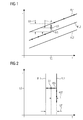
- FIG. 1 shows a schematic view in diagram form of a number of driving lines FL1, FL2, FL3 for operating a gas turbine, which are substantially parallel to each other.
- the driving lines FL1, FL2, FL3 can be described as a function of the temperature T as a function of the power L of the gas turbine 1 (not shown here) or as a function of the power L as a function of the temperature T.
- the shown driving lines FL1, FL2, FL3 point in this case with increasing temperature T a uniform increase in power L on.
- such a course of the driving line is characterized, for example, by increased addition of fuel to the individual burners or burner stages of the gas turbine 1.
- the driving lines FL1, FL2 and FL3 can be easily described by merely increasing the total amount of fuel, for example, given an already existing and fixed distribution of the individual proportional fuel quantities for the burner stages or burner stages of the gas turbine 1.
- the individual driving lines FL1, FL2, FL3 may differ in that the proportional amounts of individual fuel streams which are supplied to the individual burners or burner stages of the gas turbine differ.
- a change of operation between an operation which uses the driving line FL2 as a reference variable should take place in that the driving line FL1 should now be used as the reference variable
- a corresponding change of the respective associated parameter set would have to be made in the regulation of the gas turbine 1.
- the driving lines FL1 and FL2 also differ in respect of the proportionate amounts of fuel to the individual burners or burner stages, this would lead to a sometimes relatively large jump in the distribution change of the fuel, which can convert the gas turbine into an unstable operating state.
- a power setpoint LS is to be determined, which is arranged between the two driving lines FL1 and FL2.
- an interpolation is performed which calculates the corresponding operating parameters for the power setpoint LS.
- a power difference LU is determined at a predetermined temperature T0, which should not change during this process, or not significantly change, which is present between the two driving lines FL2 and FL1 at a substantially constant predetermined temperature value T0.
- a power deviation LA becomes the predetermined power setpoint LS of the second driving lines FL2 also determined at substantially kontantem predetermined temperature value T0.
- an interpolated travel line deviation IFA can be determined via a simple three-rate calculation, which as it were includes all operating parameters for a driving line FL but refers to an intermediate position between the two driving lines FL1 and FL2. If this interpolated driving-route deviation IFA is now added by calculation to the second driving line FL2 as well, a new driving-route course can be defined which approximately connects the driving-line 2 with the driving-line 1 (see the highlighted areas of the respective driving-lines).
- the intermediate states thus calculated are not only different with respect to the parameters of the proportionate individual fuel mass flows, but also approximately different with respect to the vane positions.
- the transition shown between the driving line FL2 and FL1 which indeed takes place at a substantially constant predetermined temperature T0, ie at substantially unchanged fuel mass flow, is typically due to a change in Ver emphasizervorleitschaufelhornen next made a change in the proportionate fuel flows to the individual burners or burner stages.
- the interpolated driving-route deviation IFA In order to calculate the interpolated driving-route deviation IFA, a difference is again calculated, but this time between the temperatures of the two driving lines at the substantially constant predetermined power LO. In addition, a deviation AST of the predetermined target value ST of the temperature T from the temperature T of the driving line FL2 at a substantially constant predetermined power LO is calculated. Again by a rule of three, the interpolated travel line deviation IFA can be calculated from these two values of the deviation AST of the predefined setpoint value ST of the temperature T and of the difference UT of the temperature T.
- the further principles in the determination of the setpoint ST of a temperature T correspond to the principles as under FIG. 1 to determine the power setpoint LS.
- the transition between the two driving lines FL2 and FL1 is primarily caused by a change in the total fuel mass flow, which is supplied to the individual burners or burner stages of the gas turbine 1 (not shown in the present case).
- FIG. 3 shows a further diagrammatic representation of different driving lines FL1, FL2, FL3 and FL4, wherein the in the Figures 1 and 2 Cases are now combined.
- the combination of the cases results in a mixing range MB in the region of the transition between the driving lines FL1, FL2 and FL3, FL4, which is shown in a checkered manner. While in FIG. 1 shown transition from the driving line FL2 to the driving line FL1 can be achieved via the power setpoint LS substantially by an adjustment of Verêtrvorleitschaufeln and the transition between the driving line FL2 and FL1 after FIG.
Priority Applications (5)
| Application Number | Priority Date | Filing Date | Title |
|---|---|---|---|
| EP15170417.8A EP3101250A1 (fr) | 2015-06-03 | 2015-06-03 | Opération d'une turbine à gaz à écart interpolé de ligne d'opépartions |
| CN201680032701.0A CN107771243B (zh) | 2015-06-03 | 2016-04-20 | 包括内插工作曲线偏差的燃气轮机的运行 |
| EP16721675.3A EP3280894B1 (fr) | 2015-06-03 | 2016-04-20 | Opération d'une turbine à gaz à écart interpolé de ligne d'opépartion |
| PCT/EP2016/058703 WO2016192890A1 (fr) | 2015-06-03 | 2016-04-20 | Fonctionnement d'une turbine à gaz avec écart de lignes directrices interpolée |
| US15/576,962 US10371058B2 (en) | 2015-06-03 | 2016-04-20 | Operation of a gas turbine comprising an interpolated operating curve deviation |
Applications Claiming Priority (1)
| Application Number | Priority Date | Filing Date | Title |
|---|---|---|---|
| EP15170417.8A EP3101250A1 (fr) | 2015-06-03 | 2015-06-03 | Opération d'une turbine à gaz à écart interpolé de ligne d'opépartions |
Publications (1)
| Publication Number | Publication Date |
|---|---|
| EP3101250A1 true EP3101250A1 (fr) | 2016-12-07 |
Family
ID=53298212
Family Applications (2)
| Application Number | Title | Priority Date | Filing Date |
|---|---|---|---|
| EP15170417.8A Withdrawn EP3101250A1 (fr) | 2015-06-03 | 2015-06-03 | Opération d'une turbine à gaz à écart interpolé de ligne d'opépartions |
| EP16721675.3A Active EP3280894B1 (fr) | 2015-06-03 | 2016-04-20 | Opération d'une turbine à gaz à écart interpolé de ligne d'opépartion |
Family Applications After (1)
| Application Number | Title | Priority Date | Filing Date |
|---|---|---|---|
| EP16721675.3A Active EP3280894B1 (fr) | 2015-06-03 | 2016-04-20 | Opération d'une turbine à gaz à écart interpolé de ligne d'opépartion |
Country Status (4)
| Country | Link |
|---|---|
| US (1) | US10371058B2 (fr) |
| EP (2) | EP3101250A1 (fr) |
| CN (1) | CN107771243B (fr) |
| WO (1) | WO2016192890A1 (fr) |
Families Citing this family (4)
| Publication number | Priority date | Publication date | Assignee | Title |
|---|---|---|---|---|
| US10961920B2 (en) | 2018-10-02 | 2021-03-30 | 8 Rivers Capital, Llc | Control systems and methods suitable for use with power production systems and methods |
| US11686258B2 (en) | 2014-11-12 | 2023-06-27 | 8 Rivers Capital, Llc | Control systems and methods suitable for use with power production systems and methods |
| US10731571B2 (en) | 2016-02-26 | 2020-08-04 | 8 Rivers Capital, Llc | Systems and methods for controlling a power plant |
| KR20220088460A (ko) | 2019-10-22 | 2022-06-27 | 8 리버스 캐피탈, 엘엘씨 | 동력 생산 시스템들 및 방법들의 열 관리를 위한 제어 계획들 |
Citations (5)
| Publication number | Priority date | Publication date | Assignee | Title |
|---|---|---|---|---|
| DE102006008483A1 (de) * | 2005-09-14 | 2007-03-22 | Mitsubishi Heavy Industries, Ltd. | Verbrennungssteuervorrichtung für eine Gasturbine |
| EP2071157A1 (fr) | 2007-12-10 | 2009-06-17 | ALSTOM Technology Ltd | Procédé de contrôle d'une turbine à gaz dans une centrale électrique et centrale électrique de mise en oeuvre du procédé |
| US20130167549A1 (en) * | 2011-12-29 | 2013-07-04 | Chad M. Holcomb | Compressor guide vane and pilot control for gas turbine engine |
| US20130227954A1 (en) * | 2012-03-05 | 2013-09-05 | Bonnie D. Marini | Gas turbine engine configured to shape power output |
| WO2015146994A1 (fr) * | 2014-03-25 | 2015-10-01 | 三菱日立パワーシステムズ株式会社 | Dispositif de commande de combustion et procédé de commande de combustion pour turbine à gaz, et programme correspondant |
Family Cites Families (1)
| Publication number | Priority date | Publication date | Assignee | Title |
|---|---|---|---|---|
| JP2002206430A (ja) * | 2001-01-10 | 2002-07-26 | Meidensha Corp | 発電方法および発電設備 |
-
2015
- 2015-06-03 EP EP15170417.8A patent/EP3101250A1/fr not_active Withdrawn
-
2016
- 2016-04-20 WO PCT/EP2016/058703 patent/WO2016192890A1/fr active Application Filing
- 2016-04-20 US US15/576,962 patent/US10371058B2/en active Active
- 2016-04-20 CN CN201680032701.0A patent/CN107771243B/zh active Active
- 2016-04-20 EP EP16721675.3A patent/EP3280894B1/fr active Active
Patent Citations (5)
| Publication number | Priority date | Publication date | Assignee | Title |
|---|---|---|---|---|
| DE102006008483A1 (de) * | 2005-09-14 | 2007-03-22 | Mitsubishi Heavy Industries, Ltd. | Verbrennungssteuervorrichtung für eine Gasturbine |
| EP2071157A1 (fr) | 2007-12-10 | 2009-06-17 | ALSTOM Technology Ltd | Procédé de contrôle d'une turbine à gaz dans une centrale électrique et centrale électrique de mise en oeuvre du procédé |
| US20130167549A1 (en) * | 2011-12-29 | 2013-07-04 | Chad M. Holcomb | Compressor guide vane and pilot control for gas turbine engine |
| US20130227954A1 (en) * | 2012-03-05 | 2013-09-05 | Bonnie D. Marini | Gas turbine engine configured to shape power output |
| WO2015146994A1 (fr) * | 2014-03-25 | 2015-10-01 | 三菱日立パワーシステムズ株式会社 | Dispositif de commande de combustion et procédé de commande de combustion pour turbine à gaz, et programme correspondant |
Also Published As
| Publication number | Publication date |
|---|---|
| EP3280894B1 (fr) | 2019-05-29 |
| US10371058B2 (en) | 2019-08-06 |
| WO2016192890A1 (fr) | 2016-12-08 |
| US20180156127A1 (en) | 2018-06-07 |
| EP3280894A1 (fr) | 2018-02-14 |
| CN107771243A (zh) | 2018-03-06 |
| CN107771243B (zh) | 2019-07-12 |
Similar Documents
| Publication | Publication Date | Title |
|---|---|---|
| EP3280894B1 (fr) | Opération d'une turbine à gaz à écart interpolé de ligne d'opépartion | |
| DE3153303C2 (de) | Verfahren und Einrichtung zum Begrenzen der bei Belastungsänderungen auftetenden thermischen Beanspruchung einer Dampfturbine | |
| DE602005000623T2 (de) | Steuerung mehrerer Vorrichtungen | |
| CH702608B1 (de) | Verfahren zum Starten einer Gasturbine und System zum Steuern eines Hochfahrvorgangs einer Gasturbine. | |
| DE3135829A1 (de) | "dampfturbinenregelverfahren und -anordnung" | |
| WO2014154374A1 (fr) | Procédé de commande et/ou de régulation, assistée par ordinateur, d'un système technique | |
| EP0642707B1 (fr) | Procede et dispositif de regulation d'un ensemble turbine-generateur | |
| EP1053512B1 (fr) | Procede et dispositif pour reguler le fonctionnement d'un groupe electrogene a turbine a gaz, en particulier de centrales electriques a gaz et a vapeur | |
| DE2900336A1 (de) | Verfahren und einrichtung zum steuern von ventilen einer dampfturbine bei einem betriebsartwechsel | |
| DE3512061C2 (de) | Steuerungssystem | |
| DE3632041A1 (de) | Verfahren und einrichtung zur regelung der leistung eines dampfkraftwerkblocks | |
| EP1490735B1 (fr) | Procede et regulateur permettant la regulation adaptative d'au moins une composante d'une installation technique | |
| EP1478986A1 (fr) | Procede et dispositif pour la regulation du regime d'un moteur a combustion interne | |
| EP0842350B1 (fr) | Systeme de regulation du regime d'une turbine et procede de regulation du regime d'une turbine pendant un delestage | |
| DE102019216401B3 (de) | Vorrichtung zum Regeln eines Ventils | |
| DE3910869C2 (de) | Reglereinheit für Gasturbinen | |
| EP0684366B1 (fr) | Procédé et système pour la commande et la régulation de la puissance d'une centrale à vapeur | |
| DE2356390C2 (de) | Verfahren zur Steuerung des Betriebs einer Dampfturbine | |
| DE10246910A1 (de) | Mehrgrößenregelungssystem und Verfahren zum Regeln einer Mehrgrößenregelstrecke | |
| EP3460202A1 (fr) | Réglage de turbine à vapeur | |
| WO2016131561A1 (fr) | Procédé pour faire fonctionner une turbine et système de turbine | |
| EP3594475A1 (fr) | Procédé de fonctionnement d'une installation de turbine à gaz à combustible gazeux | |
| DE19828446C1 (de) | Verfahren zur koordinierten Regelung eines Dampfkraftwerksblockes | |
| DE102012104359B4 (de) | Verfahren und Vorrichtung zum Ansteuern mehrerer Stellglieder | |
| DE102016220846A1 (de) | Dampfturbine und Verfahren zum Betreiben einer Dampfturbine |
Legal Events
| Date | Code | Title | Description |
|---|---|---|---|
| PUAI | Public reference made under article 153(3) epc to a published international application that has entered the european phase |
Free format text: ORIGINAL CODE: 0009012 |
|
| AK | Designated contracting states |
Kind code of ref document: A1 Designated state(s): AL AT BE BG CH CY CZ DE DK EE ES FI FR GB GR HR HU IE IS IT LI LT LU LV MC MK MT NL NO PL PT RO RS SE SI SK SM TR |
|
| AX | Request for extension of the european patent |
Extension state: BA ME |
|
| RAP1 | Party data changed (applicant data changed or rights of an application transferred) |
Owner name: SIEMENS AKTIENGESELLSCHAFT |
|
| STAA | Information on the status of an ep patent application or granted ep patent |
Free format text: STATUS: THE APPLICATION IS DEEMED TO BE WITHDRAWN |
|
| 18D | Application deemed to be withdrawn |
Effective date: 20170608 |