EP3101250A1 - Operation of a gas turbine with an interpolated operating line deviation - Google Patents
Operation of a gas turbine with an interpolated operating line deviation Download PDFInfo
- Publication number
- EP3101250A1 EP3101250A1 EP15170417.8A EP15170417A EP3101250A1 EP 3101250 A1 EP3101250 A1 EP 3101250A1 EP 15170417 A EP15170417 A EP 15170417A EP 3101250 A1 EP3101250 A1 EP 3101250A1
- Authority
- EP
- European Patent Office
- Prior art keywords
- gas turbine
- power
- driving lines
- temperature
- driving
- Prior art date
- Legal status (The legal status is an assumption and is not a legal conclusion. Google has not performed a legal analysis and makes no representation as to the accuracy of the status listed.)
- Withdrawn
Links
Images

Classifications
-
- F—MECHANICAL ENGINEERING; LIGHTING; HEATING; WEAPONS; BLASTING
- F02—COMBUSTION ENGINES; HOT-GAS OR COMBUSTION-PRODUCT ENGINE PLANTS
- F02C—GAS-TURBINE PLANTS; AIR INTAKES FOR JET-PROPULSION PLANTS; CONTROLLING FUEL SUPPLY IN AIR-BREATHING JET-PROPULSION PLANTS
- F02C7/00—Features, components parts, details or accessories, not provided for in, or of interest apart form groups F02C1/00 - F02C6/00; Air intakes for jet-propulsion plants
- F02C7/22—Fuel supply systems
- F02C7/228—Dividing fuel between various burners
-
- F—MECHANICAL ENGINEERING; LIGHTING; HEATING; WEAPONS; BLASTING
- F02—COMBUSTION ENGINES; HOT-GAS OR COMBUSTION-PRODUCT ENGINE PLANTS
- F02C—GAS-TURBINE PLANTS; AIR INTAKES FOR JET-PROPULSION PLANTS; CONTROLLING FUEL SUPPLY IN AIR-BREATHING JET-PROPULSION PLANTS
- F02C9/00—Controlling gas-turbine plants; Controlling fuel supply in air- breathing jet-propulsion plants
- F02C9/26—Control of fuel supply
- F02C9/28—Regulating systems responsive to plant or ambient parameters, e.g. temperature, pressure, rotor speed
-
- F—MECHANICAL ENGINEERING; LIGHTING; HEATING; WEAPONS; BLASTING
- F05—INDEXING SCHEMES RELATING TO ENGINES OR PUMPS IN VARIOUS SUBCLASSES OF CLASSES F01-F04
- F05D—INDEXING SCHEME FOR ASPECTS RELATING TO NON-POSITIVE-DISPLACEMENT MACHINES OR ENGINES, GAS-TURBINES OR JET-PROPULSION PLANTS
- F05D2270/00—Control
- F05D2270/01—Purpose of the control system
- F05D2270/05—Purpose of the control system to affect the output of the engine
- F05D2270/053—Explicitly mentioned power
-
- F—MECHANICAL ENGINEERING; LIGHTING; HEATING; WEAPONS; BLASTING
- F05—INDEXING SCHEMES RELATING TO ENGINES OR PUMPS IN VARIOUS SUBCLASSES OF CLASSES F01-F04
- F05D—INDEXING SCHEME FOR ASPECTS RELATING TO NON-POSITIVE-DISPLACEMENT MACHINES OR ENGINES, GAS-TURBINES OR JET-PROPULSION PLANTS
- F05D2270/00—Control
- F05D2270/01—Purpose of the control system
- F05D2270/10—Purpose of the control system to cope with, or avoid, compressor flow instabilities
-
- F—MECHANICAL ENGINEERING; LIGHTING; HEATING; WEAPONS; BLASTING
- F05—INDEXING SCHEMES RELATING TO ENGINES OR PUMPS IN VARIOUS SUBCLASSES OF CLASSES F01-F04
- F05D—INDEXING SCHEME FOR ASPECTS RELATING TO NON-POSITIVE-DISPLACEMENT MACHINES OR ENGINES, GAS-TURBINES OR JET-PROPULSION PLANTS
- F05D2270/00—Control
- F05D2270/01—Purpose of the control system
- F05D2270/14—Purpose of the control system to control thermoacoustic behaviour in the combustion chambers
-
- F—MECHANICAL ENGINEERING; LIGHTING; HEATING; WEAPONS; BLASTING
- F05—INDEXING SCHEMES RELATING TO ENGINES OR PUMPS IN VARIOUS SUBCLASSES OF CLASSES F01-F04
- F05D—INDEXING SCHEME FOR ASPECTS RELATING TO NON-POSITIVE-DISPLACEMENT MACHINES OR ENGINES, GAS-TURBINES OR JET-PROPULSION PLANTS
- F05D2270/00—Control
- F05D2270/30—Control parameters, e.g. input parameters
- F05D2270/303—Temperature
-
- F—MECHANICAL ENGINEERING; LIGHTING; HEATING; WEAPONS; BLASTING
- F05—INDEXING SCHEMES RELATING TO ENGINES OR PUMPS IN VARIOUS SUBCLASSES OF CLASSES F01-F04
- F05D—INDEXING SCHEME FOR ASPECTS RELATING TO NON-POSITIVE-DISPLACEMENT MACHINES OR ENGINES, GAS-TURBINES OR JET-PROPULSION PLANTS
- F05D2270/00—Control
- F05D2270/30—Control parameters, e.g. input parameters
- F05D2270/309—Rate of change of parameters
-
- F—MECHANICAL ENGINEERING; LIGHTING; HEATING; WEAPONS; BLASTING
- F05—INDEXING SCHEMES RELATING TO ENGINES OR PUMPS IN VARIOUS SUBCLASSES OF CLASSES F01-F04
- F05D—INDEXING SCHEME FOR ASPECTS RELATING TO NON-POSITIVE-DISPLACEMENT MACHINES OR ENGINES, GAS-TURBINES OR JET-PROPULSION PLANTS
- F05D2270/00—Control
- F05D2270/30—Control parameters, e.g. input parameters
- F05D2270/335—Output power or torque
-
- F—MECHANICAL ENGINEERING; LIGHTING; HEATING; WEAPONS; BLASTING
- F05—INDEXING SCHEMES RELATING TO ENGINES OR PUMPS IN VARIOUS SUBCLASSES OF CLASSES F01-F04
- F05D—INDEXING SCHEME FOR ASPECTS RELATING TO NON-POSITIVE-DISPLACEMENT MACHINES OR ENGINES, GAS-TURBINES OR JET-PROPULSION PLANTS
- F05D2270/00—Control
- F05D2270/70—Type of control algorithm
- F05D2270/701—Type of control algorithm proportional
-
- F—MECHANICAL ENGINEERING; LIGHTING; HEATING; WEAPONS; BLASTING
- F05—INDEXING SCHEMES RELATING TO ENGINES OR PUMPS IN VARIOUS SUBCLASSES OF CLASSES F01-F04
- F05D—INDEXING SCHEME FOR ASPECTS RELATING TO NON-POSITIVE-DISPLACEMENT MACHINES OR ENGINES, GAS-TURBINES OR JET-PROPULSION PLANTS
- F05D2270/00—Control
- F05D2270/70—Type of control algorithm
- F05D2270/708—Type of control algorithm with comparison tables
-
- F—MECHANICAL ENGINEERING; LIGHTING; HEATING; WEAPONS; BLASTING
- F23—COMBUSTION APPARATUS; COMBUSTION PROCESSES
- F23N—REGULATING OR CONTROLLING COMBUSTION
- F23N2225/00—Measuring
- F23N2225/08—Measuring temperature
-
- F—MECHANICAL ENGINEERING; LIGHTING; HEATING; WEAPONS; BLASTING
- F23—COMBUSTION APPARATUS; COMBUSTION PROCESSES
- F23N—REGULATING OR CONTROLLING COMBUSTION
- F23N2241/00—Applications
- F23N2241/20—Gas turbines
Definitions
- the present invention relates to an operating method for a gas turbine at partial load operation.
- gas turbines follow a pre-programmed control with suitable control parameters in such a partial load operation, which can also be provided as a driving line over a larger operating range.
- a set of driving lines in the control can be predetermined in which predetermined temperature values are assigned to the selected power values of the gas turbine.
- This temperature value corresponds to a temperature value relevant for the determination of the power of the gas turbine, which may be approximately the turbine inlet temperature or also the turbine outlet temperature.
- the relevant driving lines serve as reference variables by means of which a desired power value can be set. In other words, these driving lines serve as a set of control setpoints to which the gas turbine control adjusts the power value.
- such driving lines may also include operating parameters with regard to the position of a variable compressor guide grille (compressor guide vanes), as well as further operating parameters, such as an amount of water injected into the gas turbine or the distribution of the fuel quantity to individual burners or burner stages in the engine Gas turbine to suit the performance of the gas turbine suitable.
- the driving lines are typically determined individually in gas turbines for a wide variety of operating methods and stored in the regulation of the gas turbine.
- the driving lines will be determined in such a way that at each point of the driving line a stable operation of the gas turbine can take place.
- the specific distribution of the fuel to different burners of the gas turbine is stored in the individual driving lines as operating parameters and typically does not change or only slightly within a driving line. If now the operation of a gas turbine along a predetermined first driving line to be changed so that this is done according to a second deviating driving line, a change between these lines is required.
- the two relevant driving lines are relatively close to each other, then a direct switching between the first driving line and the second driving line can possibly be carried out without instabilities in operation of the gas turbine being expected.
- the two driving lines are relatively far apart, the gas turbine can be converted into an unstable operating range due to this change, which in the worst case even leads to an emergency shutdown of the gas turbine.
- an operating method for a gas turbine is to be specified, which also largely controls the change between individual driving lines of the gas turbine control and makes it trouble-free.
- the scheme should also be able to make this controlled and stable in jumps between two lines, which typically can not be made without disruption without further precautions.
- gas turbine control which is designed to perform a method as shown above and also below.
- a gas turbine comprising such a gas turbine control.
- a driving line is initially to be understood as a function of the temperature of the power, wherein each driving line is assigned a fixed parameter set.
- a driving line may also be understood as a function of power from a temperature.
- the driving lines In addition to a temperature which is relevant for the power operation of the gas turbine and can also be used to determine the power of the gas turbine, the driving lines also have an output which is output by the gas turbine during the partial load operation. Furthermore, however, the driving lines also have operating parameters which relate, in particular, to the fuel distribution, wherein the parameters determine how much fuel is to be proportionally supplied to the individual burners of the gas turbine or burner stages. With regard to the fuel distribution of two different driving lines, these parameter sets typically also differ in that the relative distribution of fuel to the individual burners or burner stages varies. If, therefore, there is a change between the two driving lines through the gas turbine control, not only is the operating parameter of the power or temperature varied, but also the proportionate distribution of fuel to the individual burners and burner stages. In addition, the driving lines can also differ by varying Verêtrleitschaufel sued.
- the fuel distribution between the individual burners or burner stages ensures a stable overall combustion when operating along a driving line.
- each new parameter sets would be used in the gas turbine control, so that when changing between two driving lines
- the relative proportion of fuel between the individual burners or burner stages would vary.
- the present invention proposes, when changing between two such driving lines, to specify a suitable power setpoint or a setpoint value of a temperature which is arranged between the two driving lines.
- the difference in performance or the difference in the temperatures of the two driving lines are initially determined and held to a certain extent as the maximum power difference or maximum difference of the temperatures.
- one of the driving lines typically the driving line provided for the current operation of the gas turbine, determines the distance to the respective desired power value and the temperature reference value, respectively, and from these values calculates a suitable power deviation of the predetermined reference value of the temperature.
- an intermediate value for the desired power value or the setpoint value of the temperature that the gas turbine control can take into account for operating the gas turbine can now be calculated.
- This intermediate value results from an interpolated driving-line deviation, from which new intermediate-parameter values are calculated in each case also for the individual parameters encompassed by the respective driving lines.
- the calculation of the interpolated travel line deviation thus serves to ensure stable operation of the gas turbine for the calculated intermediate values.
- the interpolated driving line deviation according to the invention now also includes a correspondingly interpolated parameter set for the respective operating parameters, the gas turbine control can thus access intermediate states even when switching between two driving lanes, which help to avoid that an unstable operating state results directly from the rapid changeover between the two driving lanes.
- the gas turbine instead of a jump between the two lines at least adjusted by setting a further intermediate value between the two lines. This can prevent undesirable high jumps between the individual operating parameters associated with the driving lines, and consequently an unnecessarily large discontinuity in operation of the gas turbine can be avoided.
- the interpolation according to the invention can be calculated by various mathematical methods, but a linear interpolation of the individual similar parameters represents the simplest and most advantageous solution.
- the individual operating parameters which are assigned to the two driving lines at a predetermined temperature value or at a predetermined power value are interpolated to the extent that the individual operating parameters are used by simple calculation in a three-set equation for calculating an intermediate state.
- the determination of the interpolated travel line deviation also includes a determination of the fuel distribution at the power setpoint or the setpoint value of the temperature. This typically differs from the fuel distribution in one of the two driving lines, since both driving lines typically have different fuel distributions.
- the interpolated driving line deviation is thus, comparable to a driving line, understood as a set of operating parameters, which includes not only the relevant temperature and power but also operating parameters with regard to the fuel distribution or the amount of air (position of the vanes of a Ver emphasizervorleitgitters). If, in addition, water is injected into the gas turbine for increased performance, the interpolated driving line deviation, as well as the driving lines, can additionally also have operating parameters which more closely determine the quantity and distribution of the injected water.
- the temperature values predetermined according to the invention in this case relate to those temperatures which are used as relevant for the operation of the gas turbine and its regulation. These are in particular measured as well as calculated temperatures, which occur in the flow channel of the gas turbine during their operation.
- the outlet temperatures at the expansion turbine (ATK) or the turbine inlet temperature (TT1) are such temperatures.
- these temperatures can be determined even more accurately by suitable calculation methods in order to be able to take into account, for example, the supply of secondary air in or after the burner space.
- the predetermined temperature values are therefore of relevance with regard to the determination of the power.
- the power according to the invention relates to the power delivered by the gas turbine during operation, which may also be referred to as a load.
- the interpolated driving line deviation calculated according to the invention is typically added to one of the two driving lines, typically the driving line currently used in the regulation of the gas turbine, whereby a new one is changed Driving line results.
- at least one intermediate state which is described by a power setpoint or a setpoint value of the temperature, is essential to this new changed driving line, wherein the relevant setpoint values are not encompassed by one of the two driving lines, which are already described in the control of the gas turbine.
- the temperature is a turbine outlet temperature.
- turbine outlet temperatures can be measured here (typically also referred to as TT2) as well as calculated turbine outlet temperatures.
- these can also be computationally thermodynamic effects, such as the secondary air supply or - discharge, corrected turbine outlet temperatures.
- These temperatures are typically present in the context of the control of a gas turbine, so that the definition of driving lines and the intermediate states to be determined can be done easily.
- the calculated turbine inlet temperature could also be used to determine the temperature.
- one of the two driving lines is the driving line currently used in the regulation of the gas turbine.
- a use is in this case when the respective driving line, which provides used as a control basis for the gas turbine parameters.
- the interpolated travel line deviation is calculated by a linear interpolation.
- Alternative approaches would be either a weighted interpolation or an interpolation by polygon trains, which can be created according to appropriate criteria.
- the linear interpolation can easily be determined mathematically as a simple deviation value, which can be calculated approximately in a rule of three. This difference thus calculated, which can also be referred to as the delta difference, can then be added to the currently used driving line for the further operation of the gas turbine, so that a new operating guide value can be determined.
- the interpolated driving line deviation takes into account or includes a change in the compressor guide vane position.
- a change in the compressor vane position can in this case already in the calculation of the power difference of the two driving lines or the determination of the difference in the temperatures of the two driving lines to be taken into account.
- driving lines which also include different values characterizing the position of the compressor guide vanes in their operating parameters.
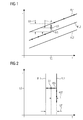
- FIG. 1 shows a schematic view in diagram form of a number of driving lines FL1, FL2, FL3 for operating a gas turbine, which are substantially parallel to each other.
- the driving lines FL1, FL2, FL3 can be described as a function of the temperature T as a function of the power L of the gas turbine 1 (not shown here) or as a function of the power L as a function of the temperature T.
- the shown driving lines FL1, FL2, FL3 point in this case with increasing temperature T a uniform increase in power L on.
- such a course of the driving line is characterized, for example, by increased addition of fuel to the individual burners or burner stages of the gas turbine 1.
- the driving lines FL1, FL2 and FL3 can be easily described by merely increasing the total amount of fuel, for example, given an already existing and fixed distribution of the individual proportional fuel quantities for the burner stages or burner stages of the gas turbine 1.
- the individual driving lines FL1, FL2, FL3 may differ in that the proportional amounts of individual fuel streams which are supplied to the individual burners or burner stages of the gas turbine differ.
- a change of operation between an operation which uses the driving line FL2 as a reference variable should take place in that the driving line FL1 should now be used as the reference variable
- a corresponding change of the respective associated parameter set would have to be made in the regulation of the gas turbine 1.
- the driving lines FL1 and FL2 also differ in respect of the proportionate amounts of fuel to the individual burners or burner stages, this would lead to a sometimes relatively large jump in the distribution change of the fuel, which can convert the gas turbine into an unstable operating state.
- a power setpoint LS is to be determined, which is arranged between the two driving lines FL1 and FL2.
- an interpolation is performed which calculates the corresponding operating parameters for the power setpoint LS.
- a power difference LU is determined at a predetermined temperature T0, which should not change during this process, or not significantly change, which is present between the two driving lines FL2 and FL1 at a substantially constant predetermined temperature value T0.
- a power deviation LA becomes the predetermined power setpoint LS of the second driving lines FL2 also determined at substantially kontantem predetermined temperature value T0.
- an interpolated travel line deviation IFA can be determined via a simple three-rate calculation, which as it were includes all operating parameters for a driving line FL but refers to an intermediate position between the two driving lines FL1 and FL2. If this interpolated driving-route deviation IFA is now added by calculation to the second driving line FL2 as well, a new driving-route course can be defined which approximately connects the driving-line 2 with the driving-line 1 (see the highlighted areas of the respective driving-lines).
- the intermediate states thus calculated are not only different with respect to the parameters of the proportionate individual fuel mass flows, but also approximately different with respect to the vane positions.
- the transition shown between the driving line FL2 and FL1 which indeed takes place at a substantially constant predetermined temperature T0, ie at substantially unchanged fuel mass flow, is typically due to a change in Ver emphasizervorleitschaufelhornen next made a change in the proportionate fuel flows to the individual burners or burner stages.
- the interpolated driving-route deviation IFA In order to calculate the interpolated driving-route deviation IFA, a difference is again calculated, but this time between the temperatures of the two driving lines at the substantially constant predetermined power LO. In addition, a deviation AST of the predetermined target value ST of the temperature T from the temperature T of the driving line FL2 at a substantially constant predetermined power LO is calculated. Again by a rule of three, the interpolated travel line deviation IFA can be calculated from these two values of the deviation AST of the predefined setpoint value ST of the temperature T and of the difference UT of the temperature T.
- the further principles in the determination of the setpoint ST of a temperature T correspond to the principles as under FIG. 1 to determine the power setpoint LS.
- the transition between the two driving lines FL2 and FL1 is primarily caused by a change in the total fuel mass flow, which is supplied to the individual burners or burner stages of the gas turbine 1 (not shown in the present case).
- FIG. 3 shows a further diagrammatic representation of different driving lines FL1, FL2, FL3 and FL4, wherein the in the Figures 1 and 2 Cases are now combined.
- the combination of the cases results in a mixing range MB in the region of the transition between the driving lines FL1, FL2 and FL3, FL4, which is shown in a checkered manner. While in FIG. 1 shown transition from the driving line FL2 to the driving line FL1 can be achieved via the power setpoint LS substantially by an adjustment of Verêtrvorleitschaufeln and the transition between the driving line FL2 and FL1 after FIG.
Abstract
Die Erfindung betrifft ein Betriebsverfahren für eine Gasturbine (1) bei Teillastbetrieb, umfassend die folgenden Schritte: - Vorgeben eines Leistungssollwerts (LS) bei einem vorbestimmten Temperaturwert (T0); - Bestimmen zweier Fahrlinien (FL) der Temperatur (T) in Abhängigkeit von der Leistung (L) der Gasturbine (1), wobei der Leistungssollwert (LS) zwischen diesen Fahrlinien (FL) angeordnet ist; - Bestimmung des Leistungsunterschieds (LU) dieser beiden Fahrlinien (FL) bei dem im Wesentlichen konstanten, vorbestimmten Temperaturwert (T0); - Bestimmung einer Leistungsabweichung (LA) des vorgegebenen Leistungssollwerts (LS) von einer der beiden Fahrlinien (FL) bei dem in Wesentlichen konstanten, vorbestimmten Temperaturwert (T0); - Berechnen einer interpolierten Fahrlinienabweichung (IFA) auf Grundlage des Leistungsunterschieds (LU) und der Leistungsabweichung (LA).The invention relates to an operating method for a gas turbine (1) under partial load operation, comprising the following steps: - Specifying a power setpoint (LS) at a predetermined temperature value (T0); Determining two driving lines (FL) of the temperature (T) as a function of the power (L) of the gas turbine (1), the power setpoint (LS) being arranged between these driving lines (FL); - determining the power difference (LU) of these two driving lines (FL) at the substantially constant, predetermined temperature value (T0); - Determining a power deviation (LA) of the predetermined power setpoint (LS) of one of the two driving lines (FL) at the substantially constant, predetermined temperature value (T0); - Compute an interpolated driving line deviation (IFA) based on the power difference (LU) and the power deviation (LA).
Description
Die vorliegende Erfindung betrifft ein Betriebsverfahren für eine Gasturbine bei Teillastbetrieb. Typischerweise folgen Gasturbinen bei einem solchen Teillastbetrieb einer vorprogrammierten Regelung mit geeigneten Regelparametern, die etwa auch als Fahrlinie über einen größeren Betriebsbereich vorgesehen sein können. So können etwa bei einem sog. Leistungsbetrieb, also einem Betrieb, bei welchem die abgegebene Leistung der Gasturbine als Regelparameter vorgesehen ist, ein Satz an Fahrlinien in der Regelung vorbestimmt sein, bei dem ausgewählten Leistungswerten der Gasturbine vorbestimmte Temperaturwerte zugordnet sind. Dieser Temperaturwert entspricht einem für die Bestimmung der Leistung der Gasturbine relevanten Temperaturwert, wobei dieser etwa die Turbineneintrittstemperatur oder auch die Turbinenaustrittstemperatur sein kann. Die betreffenden Fahrlinien dienen während des Leistungsbetriebs als Führungsgrößen, mittels welcher ein gewünschter Leistungswert eingestellt werden kann. In anderen Worten dienen diese Fahrlinien als ein Satz an Regelsollwerten, auf welche die Gasturbinenregelung den Leistungswert einstellt.The present invention relates to an operating method for a gas turbine at partial load operation. Typically, gas turbines follow a pre-programmed control with suitable control parameters in such a partial load operation, which can also be provided as a driving line over a larger operating range. For example, in a so-called power operation, ie an operation in which the output power of the gas turbine is provided as a control parameter, a set of driving lines in the control can be predetermined in which predetermined temperature values are assigned to the selected power values of the gas turbine. This temperature value corresponds to a temperature value relevant for the determination of the power of the gas turbine, which may be approximately the turbine inlet temperature or also the turbine outlet temperature. During the power operation, the relevant driving lines serve as reference variables by means of which a desired power value can be set. In other words, these driving lines serve as a set of control setpoints to which the gas turbine control adjusts the power value.
Zusätzlich zu derartigen Temperaturwerten können solche Fahrlinien aber etwa auch noch Betriebsparameter hinsichtlich der Stellung eines variablen Verdichterleitgitters (Verdichterleitschaufeln) umfassen, wie auch weitere Betriebsparameter, etwa eine Menge an in die Gasturbine eingedüstem Wasser oder auch die Verteilung der Brennstoffmenge an einzelne Brenner oder Brennerstufen in der Gasturbine, um die Leistung der Gasturbine geeignet anzupassen.In addition to such temperature values, however, such driving lines may also include operating parameters with regard to the position of a variable compressor guide grille (compressor guide vanes), as well as further operating parameters, such as an amount of water injected into the gas turbine or the distribution of the fuel quantity to individual burners or burner stages in the engine Gas turbine to suit the performance of the gas turbine suitable.
Die Fahrlinien werden in Gasturbinen typischerweise für unterschiedlichste Betriebsverfahren einzeln festgelegt und in der Regelung der Gasturbine hinterlegt. Die Fahrlinien werden hierbei derart bestimmt, dass bei jedem Punkt der Fahrlinie ein stabiler Betrieb der Gasturbine erfolgen kann. Insbesondere die konkrete Verteilung des Brennstoffs an verschiedene Brenner der Gasturbine ist in den einzelnen Fahrlinien als Betriebsparameter hinterlegt und ändert sich typischerweise innerhalb einer Fahrlinie nicht oder nur kaum. Soll nun der Betrieb einer Gasturbine entlang einer vorbestimmten ersten Fahrlinie dahingehend geändert werden, dass dieser gemäß einer zweiten davon abweichenden Fahrlinie erfolgt, ist ein Wechseln zwischen diesen Fahrlinien erforderlich. Liegen die beiden betreffenden Fahrlinien verhältnismäßig eng aneinander, kann möglicherweise ein direktes Umschalten zwischen erster Fahrlinie und zweiter Fahrlinie vorgenommen werden, ohne dass mit Instabilitäten bei Betrieb der Gasturbine zu rechnen ist. Liegen die beiden Fahrlinien jedoch verhältnismäßig weit auseinander, kann aufgrund dieses Wechsels die Gasturbine in einen instabilen Betriebsbereich überführt werden, welcher im schlimmsten Fall sogar zu einer Notabschaltung der Gasturbine führt.The driving lines are typically determined individually in gas turbines for a wide variety of operating methods and stored in the regulation of the gas turbine. The driving lines will be determined in such a way that at each point of the driving line a stable operation of the gas turbine can take place. In particular, the specific distribution of the fuel to different burners of the gas turbine is stored in the individual driving lines as operating parameters and typically does not change or only slightly within a driving line. If now the operation of a gas turbine along a predetermined first driving line to be changed so that this is done according to a second deviating driving line, a change between these lines is required. If the two relevant driving lines are relatively close to each other, then a direct switching between the first driving line and the second driving line can possibly be carried out without instabilities in operation of the gas turbine being expected. However, if the two driving lines are relatively far apart, the gas turbine can be converted into an unstable operating range due to this change, which in the worst case even leads to an emergency shutdown of the gas turbine.
Zwar wird im Stand der Technik, etwa wie der
Insbesondere aufgrund der zwischen zwei Fahrlinien unterschiedlichen Verteilung von Brennstoff an die einzelnen Brenner bzw. Brennerstufen der Gasturbine können bei Wechsel zwischen zwei Fahrlinien verhältnismäßig abrupte Änderungen im Verbrennungsraum erfolgen, die den Gasturbinenbetrieb wenigstens zeitweilig instabil werden lassen. Zwar wird bei Betrieb entlang einer Fahrlinie typischerweise ein Betriebspunkt durch geeignetes Regeln der Gasturbine weitgehend stabil gehalten, jedoch ist diese Regelung meist nur für den Ausgleich kleinerer Abweichungen ausgelegt. Geringe Abweichungen entlang einer Fahrlinie verlaufen insofern meist störungsfrei. Abweichungen jedoch, welche beim Betrieb über mehrere Fahrlinien hinweg entstehen, kann die Gasturbinenregelung mitunter nicht störungsfrei ausregeln.In particular, due to the different between two driving lines distribution of fuel to the individual burner or burner stages of the gas turbine relatively abrupt changes in the combustion chamber can take place when switching between two driving lines, which can be at least temporarily unstable gas turbine operation. Although, during operation along a driving line, an operating point is typically kept largely stable by suitable regulation of the gas turbine, however, this control is usually designed only to compensate for minor deviations. Small deviations along a driving line are therefore usually trouble-free. Deviations, however, which arise during operation over several driving lines, the gas turbine control can sometimes not trouble-free.
Insofern stellt sich das technische Erfordernis, ein geeignetes Betriebsverfahren für eine Gasturbine bei Teillastbetrieb anzugeben, welche die aus dem Stand der Technik bekannten Nachteile vermeiden kann. Insbesondere ist ein Betriebsverfahren für eine Gasturbine anzugeben, welches auch den Wechsel zwischen einzelnen Fahrlinien der Gasturbinenregelung weitgehend kontrolliert und störungsfrei vornehmen lässt. In anderen Worten soll die Regelung auch in der Lage sein, bei Sprüngen zwischen zwei Fahrlinien, welche typischerweise ohne weitere Vorkehrungen nicht störungsfrei vorgenommen werden können, diese dennoch kontrolliert und stabil erfolgen zu lassen.In this respect, there is the technical requirement to provide a suitable operating method for a gas turbine at partial load operation, which can avoid the disadvantages known from the prior art. In particular, an operating method for a gas turbine is to be specified, which also largely controls the change between individual driving lines of the gas turbine control and makes it trouble-free. In other words, the scheme should also be able to make this controlled and stable in jumps between two lines, which typically can not be made without disruption without further precautions.
Diese der Erfindung zugrundeliegenden Aufgaben werden gelöst durch ein Betriebsverfahren für eine Gasturbine bei Teillastbetrieb gemäß Ansprüchen 1 und 2 sowie durch eine Gasturbinenregelung gemäß Anspruch 8, wie auch durch eine Gasturbine gemäß Anspruch 9.These objects of the invention are achieved by an operating method for a gas turbine at part load operation according to claims 1 and 2 and by a gas turbine control according to claim 8, as well as by a gas turbine according to claim 9.
Insbesondere werden die der Erfindung zugrundeliegenden Aufgaben gelöst durch ein Betriebsverfahren für eine Gasturbine bei Teillast, umfassend die folgenden Schritte:
- Vorgeben eines Leistungssollwerts bei einem vorbestimmten Temperaturwert;
- Bestimmen zweier Fahrlinien der Temperatur in Abhängigkeit von der Leistung der Gasturbine, wobei der Leistungssollwert zwischen diesen Fahrlinien angeordnet ist;
- Bestimmung des Leistungsunterschieds dieser beiden Fahrlinien bei dem im Wesentlichen konstanten, vorbestimmten Temperaturwert;
- Bestimmung einer Leistungsabweichung des vorgegebenen Leistungssollwerts von einer der beiden Fahrlinien bei dem im Wesentlichen konstanten, vorbestimmten Temperaturwert;
- Berechnen einer interpolierten Fahrlinienabweichung auf Grundlage des Leistungsunterschieds und der Leistungsabweichung.
- Specifying a power setpoint at a predetermined temperature value;
- Determining two driving lines of the temperature as a function of the power of the gas turbine, the power setpoint being arranged between these driving lines;
- Determining the power difference of these two driving lines at the substantially constant, predetermined temperature value;
- Determining a power deviation of the predetermined power setpoint from one of the two driving lines at the substantially constant, predetermined temperature value;
- Calculating an interpolated travel line deviation based on the power difference and the power deviation.
Weiterhin werden die der Erfindung zugrundeliegenden Aufgaben gelöst durch ein Betriebsverfahren für eine Gasturbine bei Teillast, umfassend die folgenden Schritte:
- Vorgeben eines Sollwerts einer Temperatur bei einer vorbestimmten Leistung;
- Bestimmen zweier Fahrlinien der Temperatur in Abhängigkeit von der Leistung der Gasturbine, wobei der Sollwert der Temperatur zwischen diesen Fahrlinien (FL) angeordnet ist;
- Bestimmung des Unterschieds der Temperaturen dieser beiden Fahrlinien bei der im Wesentlichen konstanten, vorbestimmten Leistung;
- Bestimmung einer Abweichung des vorgegebenen Sollwerts der Temperatur von der Temperatur einer der beiden Fahrlinien bei der im Wesentlichen konstanten, vorbestimmten Leistung;
- Berechnen einer interpolierten Fahrlinienabweichung auf Grundlage des Unterschieds der Temperaturen und der Abweichung des Sollwerts der Temperatur.
- Providing a setpoint of a temperature at a predetermined power;
- Determining two driving lines of the temperature in dependence on the power of the gas turbine, wherein the set value of the temperature between these driving lines (FL) is arranged;
- Determining the difference in the temperatures of these two driving lines at the substantially constant, predetermined power;
- Determining a deviation of the predetermined target value of the temperature from the temperature of one of the two driving lines at the substantially constant, predetermined power;
- Calculating an interpolated travel line deviation based on the difference of the temperatures and the deviation of the setpoint of the temperature.
Weiterhin werden die der Erfindung zugrundeliegenden Aufgaben gelöst durch eine Gasturbinenregelung, welche dazu ausgebildet ist, ein Verfahren, wie oben wie auch nachfolgend dargestellt, auszuführen.Furthermore, the objects underlying the invention are achieved by a gas turbine control, which is designed to perform a method as shown above and also below.
Ebenso werden die der Erfindung zugrundeliegenden Aufgaben gelöst durch eine Gasturbine umfassend eine solche Gasturbinenregelung.Likewise, the objects underlying the invention are achieved by a gas turbine comprising such a gas turbine control.
Erfindungsgemäß ist eine Fahrlinie zunächst als eine Funktion der Temperatur von der Leistung zu verstehen, wobei jeder Fahrlinie ein fester Parametersatz zugeordnet ist. Alternativ kann eine Fahrlinie auch als eine Funktion der Leistung von einer Temperatur zu verstehen sein. Im Rahmen der weiteren Erklärungen soll jedoch nicht zwischen diesen beiden Fällen explizit unterschieden werden. Insbesondere, wenn die jeweiligen Funktionen eindeutig sind, ist eine Unterscheidung ohnehin nicht erforderlich.According to the invention, a driving line is initially to be understood as a function of the temperature of the power, wherein each driving line is assigned a fixed parameter set. Alternatively, a driving line may also be understood as a function of power from a temperature. In the further explanations, however, no distinction should be made between these two cases. In particular, if the respective functions are unique, a distinction is not required anyway.
Die Fahrlinien weisen also neben einer Temperatur, welche für den Leistungsbetrieb der Gasturbine relevant ist und zur Leistungsbestimmung der Gasturbine mit herangezogen werden kann, auch eine Leistung auf, welche während des Teillastbetriebes durch die Gasturbine abgegeben wird. Weiterhin weisen die Fahrlinien jedoch auch noch Betriebsparameter auf, welche insbesondere die Brennstoffverteilung betreffen, wobei die Parameter festlegen, wie viel Brennstoff anteilig den einzelnen Brennern der Gasturbine bzw. Brennerstufen zuzuführen ist. Typischerweise unterscheiden sich diese Parametersätze hinsichtlich der Brennstoffverteilung zweier unterschiedlicher Fahrlinien auch dahingehend, dass die relative Verteilung von Brennstoff an die einzelnen Brenner bzw. Brennerstufen variiert. Wird also zwischen zwei Fahrlinien durch die Gasturbinenregelung gewechselt, wird nicht nur der Betriebsparameter der Leistung bzw. Temperatur variiert sondern auch etwa die anteilige Brennstoffverteilung an die einzelnen Brenner und Brennerstufen. Zudem können sich die Fahrlinien auch durch variierende Verdichterleitschaufelstellungen unterscheiden.In addition to a temperature which is relevant for the power operation of the gas turbine and can also be used to determine the power of the gas turbine, the driving lines also have an output which is output by the gas turbine during the partial load operation. Furthermore, however, the driving lines also have operating parameters which relate, in particular, to the fuel distribution, wherein the parameters determine how much fuel is to be proportionally supplied to the individual burners of the gas turbine or burner stages. With regard to the fuel distribution of two different driving lines, these parameter sets typically also differ in that the relative distribution of fuel to the individual burners or burner stages varies. If, therefore, there is a change between the two driving lines through the gas turbine control, not only is the operating parameter of the power or temperature varied, but also the proportionate distribution of fuel to the individual burners and burner stages. In addition, the driving lines can also differ by varying Verdichterleitschaufelstellungen.
Insbesondere die Brennstoffverteilung zwischen den einzelnen Brennern bzw. Brennerstufen gewährleistet bei Betrieb entlang einer Fahrlinie eine stabile Gesamtverbrennung. Soll nun jedoch zwischen den zwei Fahrlinien gewechselt werden, würden in der Gasturbinenregelung jeweils neue Parametersätze zur Anwendung kommen, so dass beim Wechsel zwischen zwei Fahrlinien auch der relative Anteil von Brennstoff zwischen den einzelnen Brennern bzw. Brennerstufen variieren würde.In particular, the fuel distribution between the individual burners or burner stages ensures a stable overall combustion when operating along a driving line. However, if now between the two driving lines to be changed, each new parameter sets would be used in the gas turbine control, so that when changing between two driving lines Also, the relative proportion of fuel between the individual burners or burner stages would vary.
Die vorliegende Erfindung schlägt nun vor, bei Wechsel zwischen zweier solcher Fahrlinien, einen geeigneten Leistungssollwert bzw. Sollwert einer Temperatur vorzugeben, der zwischen den beiden Fahrlinien angeordnet ist. Um nun einen stabilen Betrieb der Gasturbine gewährleisten zu können, werden zunächst der Leistungsunterschied bzw. der Unterschied der Temperaturen der beiden Fahrlinien bestimmt und gewissermaßen als maximaler Leistungsunterschied bzw. maximaler Unterschied der Temperaturen bereitgehalten. Ebenso wird von einer der Fahrlinien, typischerweise der zum aktuellen Betrieb der Gasturbine vorgesehenen Fahrlinie, der Abstand zu dem jeweiligen Leistungssollwert bzw. dem Sollwert der Temperatur bestimmt, und aus diesen Werten eine geeignete Leistungsabweichung bzw. Leistungsabweichung des vorgegebenen Sollwerts der Temperatur berechnet. Aufgrund der berechneten Leistungsunterschiede und Leistungsabweichungen bzw. aufgrund der Unterschiede der Temperaturen und der Abweichung des Sollwerts der Temperaturen kann nun ein Zwischenwert für den Leistungssollwert bzw. den Sollwert der Temperatur errechnet werden, den die Gasturbinenregelung zum Betrieb der Gasturbine berücksichtigen kann. Dieser Zwischenwert ergibt sich aus einer interpolierten Fahrlinienabweichung, aus welcher auch für die von den jeweiligen Fahrlinien umfassten einzelnen Parameter jeweils neue Zwischenparameterwerte berechnet werden.The present invention proposes, when changing between two such driving lines, to specify a suitable power setpoint or a setpoint value of a temperature which is arranged between the two driving lines. In order to be able to ensure a stable operation of the gas turbine, the difference in performance or the difference in the temperatures of the two driving lines are initially determined and held to a certain extent as the maximum power difference or maximum difference of the temperatures. Likewise, one of the driving lines, typically the driving line provided for the current operation of the gas turbine, determines the distance to the respective desired power value and the temperature reference value, respectively, and from these values calculates a suitable power deviation of the predetermined reference value of the temperature. Based on the calculated power differences and power deviations or due to the differences in the temperatures and the deviation of the setpoint of the temperatures, an intermediate value for the desired power value or the setpoint value of the temperature that the gas turbine control can take into account for operating the gas turbine can now be calculated. This intermediate value results from an interpolated driving-line deviation, from which new intermediate-parameter values are calculated in each case also for the individual parameters encompassed by the respective driving lines.
Die Berechnung der interpolierten Fahrlinienabweichung dient also dazu, für die berechneten Zwischenwerte auch einen stabilen Betrieb der Gasturbine gewährleisten zu können. Da die erfindungsgemäße interpolierte Fahrlinienabweichung nun auch einen entsprechend interpolierten Parametersatz für die jeweiligen Betriebsparameter umfasst, kann also die Gasturbinenregelung auch bei Wechsel zwischen zwei Fahrlinien auf Zwischenzustände zugreifen, die vermeiden helfen, dass durch den raschen Wechsel zwischen den beiden Fahrlinien direkt ein instabiler Betriebszustand resultiert. Erfindungsgemäß wird also die Gasturbine anstelle eines Sprunges zwischen den zwei Fahrlinien wenigstens durch Einstellen eines weiteren Zwischenwertes zwischen den beiden Fahrlinien ausgeregelt. Damit kann verhindert werden, dass ungewünscht hohe Sprünge zwischen den einzelnen Betriebsparametern, die den Fahrlinien zugeordnet sind, erfolgen, und folglich kann eine unnötig starke Diskontinuität bei Betrieb der Gasturbine vermieden werden.The calculation of the interpolated travel line deviation thus serves to ensure stable operation of the gas turbine for the calculated intermediate values. Since the interpolated driving line deviation according to the invention now also includes a correspondingly interpolated parameter set for the respective operating parameters, the gas turbine control can thus access intermediate states even when switching between two driving lanes, which help to avoid that an unstable operating state results directly from the rapid changeover between the two driving lanes. According to the invention So the gas turbine instead of a jump between the two lines at least adjusted by setting a further intermediate value between the two lines. This can prevent undesirable high jumps between the individual operating parameters associated with the driving lines, and consequently an unnecessarily large discontinuity in operation of the gas turbine can be avoided.
Die erfindungsgemäße Interpolation kann hierbei durch verschiedene mathematische Verfahren berechnet werden, wobei jedoch eine lineare Interpolation der einzelnen gleichartigen Parameter die einfachste und vorteilhafteste Lösung darstellt. In anderen Worten werden die einzelnen Betriebsparameter, welche etwa den zwei Fahrlinien bei einem vorbestimmten Temperaturwert bzw. bei einem vorbestimmten Leistungswert zugeordnet sind, insoweit interpoliert, dass die einzelnen Betriebsparameter durch einfache Berechnung in einer Dreisatzgleichung zur Berechnung eines Zwischenzustandes herangezogen werden.In this case, the interpolation according to the invention can be calculated by various mathematical methods, but a linear interpolation of the individual similar parameters represents the simplest and most advantageous solution. In other words, the individual operating parameters which are assigned to the two driving lines at a predetermined temperature value or at a predetermined power value are interpolated to the extent that the individual operating parameters are used by simple calculation in a three-set equation for calculating an intermediate state.
Die Bestimmung der interpolierten Fahrlinienabweichung umfasst insbesondere auch eine Bestimmung der Brennstoffverteilung bei dem Leistungssollwert bzw. dem Sollwert der Temperatur. Diese unterscheidet sich typischerweise von der Brennstoffverteilung bei einer der beiden Fahrlinien, da beide Fahrlinien typischerweise unterschiedliche Brennstoffverteilungen aufweisen. Die interpolierte Fahrlinienabweichung ist also, vergleichbar etwa einer Fahrlinie, als Satz an Betriebsparametern zu verstehen, welcher etwa neben der relevanten Temperatur und der Leistung auch Betriebsparameter hinsichtlich der Brennstoffverteilung oder auch der Luftmenge (Stellung der Leitschaufeln eines Verdichtervorleitgitters) umfassen. Wird zudem noch Wasser in die Gasturbine zur Leistungssteigerung eingedüst, kann die interpolierte Fahrlinienabweichung ebenso wie die Fahrlinien auch zusätzlich noch Betriebsparameter aufweisen, die die Menge und Verteilung des eingedüsten Wassers näher bestimmen.In particular, the determination of the interpolated travel line deviation also includes a determination of the fuel distribution at the power setpoint or the setpoint value of the temperature. This typically differs from the fuel distribution in one of the two driving lines, since both driving lines typically have different fuel distributions. The interpolated driving line deviation is thus, comparable to a driving line, understood as a set of operating parameters, which includes not only the relevant temperature and power but also operating parameters with regard to the fuel distribution or the amount of air (position of the vanes of a Verdichtervorleitgitters). If, in addition, water is injected into the gas turbine for increased performance, the interpolated driving line deviation, as well as the driving lines, can additionally also have operating parameters which more closely determine the quantity and distribution of the injected water.
An dieser Stelle ist nochmals anzumerken, dass die erfindungsgemäß vorbestimmten Temperaturwerte hierbei solche Temperaturen betreffen, welche für den Betrieb der Gasturbine und deren Regelung als relevant herangezogen werden. Diese sind insbesondere gemessene wie auch berechnete Temperaturen, welche im Strömungskanal der Gasturbine während deren Betrieb auftreten. So sind etwa die Austrittstemperaturen an der Entspannungsturbine (ATK) oder auch die Turbineneintrittstemperatur (TT1) derartige Temperaturen. Diese Temperaturen können bspw. durch geeignete Berechnungsverfahren noch weiter genauer bestimmt werden, um etwa auch die Zuführung von Sekundärluft in oder nach dem Brennerraum berücksichtigen zu können. Die vorbestimmten Temperaturwerte sind also hinsichtlich der Leistungsbestimmung von Relevanz.It should again be noted at this point that the temperature values predetermined according to the invention in this case relate to those temperatures which are used as relevant for the operation of the gas turbine and its regulation. These are in particular measured as well as calculated temperatures, which occur in the flow channel of the gas turbine during their operation. For example, the outlet temperatures at the expansion turbine (ATK) or the turbine inlet temperature (TT1) are such temperatures. For example, these temperatures can be determined even more accurately by suitable calculation methods in order to be able to take into account, for example, the supply of secondary air in or after the burner space. The predetermined temperature values are therefore of relevance with regard to the determination of the power.
Die erfindungsgemäße Leistung betrifft die bei Betrieb der durch die Gasturbine abgegebene Leistung, welche auch als Last bezeichnet werden kann.The power according to the invention relates to the power delivered by the gas turbine during operation, which may also be referred to as a load.
Um eine Gasturbine, welche bspw. entlang einer ersten Fahrlinie betrieben wird, auch im erfindungsgemäßen Sinn betreiben zu können, wird typischerweise die erfindungsgemäß berechnete interpolierte Fahrlinienabweichung einer der beiden Fahrlinien zugeschlagen, typischerweise der aktuell bei der Regelung der Gasturbine benutzten Fahrlinie, wodurch eine neue veränderte Fahrlinie resultiert. Wesentlich an dieser neuen geänderten Fahrlinie ist jedoch mindestens eine Zwischenzustand, welcher durch einen Leistungssollwert bzw. einen Sollwert der Temperatur beschrieben wird, wobei die betreffenden Sollwerte nicht von einer der beiden Fahrlinien, die bereits vorbeschrieben in der Regelung der Gasturbine hinterlegt sind, umfasst sind.In order to be able to operate a gas turbine, which is operated, for example, along a first driving line, in the sense of the invention, the interpolated driving line deviation calculated according to the invention is typically added to one of the two driving lines, typically the driving line currently used in the regulation of the gas turbine, whereby a new one is changed Driving line results. However, at least one intermediate state, which is described by a power setpoint or a setpoint value of the temperature, is essential to this new changed driving line, wherein the relevant setpoint values are not encompassed by one of the two driving lines, which are already described in the control of the gas turbine.
Gemäß einer ersten besonders bevorzugten Ausführungsform der Erfindung ist vorgesehen, dass die Temperatur eine Turbinenaustrittstemperatur ist. Diese Turbinenaustrittstemperaturen können hierbei gemessene (typischerweise auch als TT2 bezeichnet) wie auch berechnete Turbinenaustrittstemperaturen sein. Insbesondere können diese auch rechnerisch um thermodynamische Effekte, wie etwa der Sekundärluftzufuhr oder - abfuhr, korrigierte Turbinenaustrittstemperaturen sein. Diese Temperaturen sind typischerweise im Rahmen der Regelung einer Gasturbine ohnehin vorhanden, so dass die Definition von Fahrlinien und der zu bestimmenden Zwischenzustände leicht erfolgen kann. Alternativ könnte auch die rechnerisch bestimmte Turbineneintrittstemperatur zur Bestimmung der Temperatur herangezogen werden.According to a first particularly preferred embodiment of the invention it is provided that the temperature is a turbine outlet temperature. These turbine outlet temperatures can be measured here (typically also referred to as TT2) as well as calculated turbine outlet temperatures. In particular, these can also be computationally thermodynamic effects, such as the secondary air supply or - discharge, corrected turbine outlet temperatures. These temperatures are typically present in the context of the control of a gas turbine, so that the definition of driving lines and the intermediate states to be determined can be done easily. Alternatively, the calculated turbine inlet temperature could also be used to determine the temperature.
Gemäß einer weiteren, besonders bevorzugten Ausführungsform der Erfindung ist vorgesehen, dass eine der beiden Fahrlinien die aktuell bei der Regelung der Gasturbine genutzte Fahrlinie ist. Eine Nutzung liegt hierbei dann vor, wenn die betreffende Fahrlinie, die als Regelungsgrundlage bei der Gasturbine benutzten Parameter zur Verfügung stellt.According to a further, particularly preferred embodiment of the invention, it is provided that one of the two driving lines is the driving line currently used in the regulation of the gas turbine. A use is in this case when the respective driving line, which provides used as a control basis for the gas turbine parameters.
Entsprechend einer besonders bevorzugten Ausführungsform der Erfindung ist vorgesehen, dass die interpolierte Fahrlinienabweichung durch eine lineare Interpolation berechnet wird. Alternative Ansätze wären entweder eine gewichtete Interpolation oder eine Interpolation durch Polygonenzüge, welche nach entsprechenden Kriterien erstellt werden kann. Die lineare Interpolation hingegen lässt sich leicht rechnerisch als einfacher Abweichungswert bestimmen, welcher etwa in einer Dreisatzgleichung berechnet werden kann. Dieser so berechnete Unterschied, welcher auch als Delta-Unterschied bezeichnet werden kann, kann für den weiteren Betrieb der Gasturbine dann der aktuell genutzten Fahrlinie zugeschlagen werden, so dass ein neuer Betriebsführungswert bestimmt werden kann.According to a particularly preferred embodiment of the invention, it is provided that the interpolated travel line deviation is calculated by a linear interpolation. Alternative approaches would be either a weighted interpolation or an interpolation by polygon trains, which can be created according to appropriate criteria. By contrast, the linear interpolation can easily be determined mathematically as a simple deviation value, which can be calculated approximately in a rule of three. This difference thus calculated, which can also be referred to as the delta difference, can then be added to the currently used driving line for the further operation of the gas turbine, so that a new operating guide value can be determined.
Gemäß einer weiteren besonders bevorzugten Ausführungsform der Erfindung ist vorgesehen, dass die interpolierte Fahrlinienabweichung eine Änderung der Verdichterleitschaufelstellung berücksichtigt, bzw. mit umfasst. Eine Änderung der Verdichterleitschaufelstellung kann hierbei bereits in der Berechnung des Leistungsunterschieds der beiden Fahrlinien oder der Bestimmung des Unterschiedes der Temperaturen der beiden Fahrlinien mit berücksichtigt sein. In anderen Worten können damit auch Fahrlinien berücksichtigt sein, die in ihren Betriebsparametern auch verschiedene, die Stellung der Verdichterleitschaufeln charakterisierenden Werte umfassen. Insofern kann auch flexibel zwischen Fahrlinien gewechselt werden, die unterschiedliche Stellungen der Verdichterleitschaufeln vorgeben.According to a further particularly preferred embodiment of the invention, it is provided that the interpolated driving line deviation takes into account or includes a change in the compressor guide vane position. A change in the compressor vane position can in this case already in the calculation of the power difference of the two driving lines or the determination of the difference in the temperatures of the two driving lines to be taken into account. In other words, it is also possible to take into account driving lines which also include different values characterizing the position of the compressor guide vanes in their operating parameters. In this respect, it is also possible to change flexibly between driving lines which specify different positions of the compressor guide vanes.
Gemäß einer weiteren besonders bevorzugten Ausführungsform der Erfindung ist vorgesehen, dass weiterhin der folgende Schritt mit umfasst ist:
- Bestimmen eines Satzes an Einzelbrennstoffmengen, welche einer Mehrzahl an Brennern bzw. Brennerstufen der Gasturbine zugeführt werden, unter Berücksichtigung der interpolierten Fahrlinienabweichung (IFA).
- Determining a set of individual fuel amounts, which are supplied to a plurality of burners or burner stages of the gas turbine, taking into account the interpolated Fahrlinienabweichung (IFA).
Nachfolgend soll die Erfindung anhand einzelner Figuren im Detail näher beschrieben werden. Hierbei ist die Erfindung lediglich schematisch dargestellt, wodurch jedoch keine Einschränkung der Ausführbarkeit der Erfindung resultiert. Weiterhin ist darauf hinzuweisen, dass alle nachfolgenden technischen Merkmale, welche mit gleichen Bezugszeichen versehen sind, gleiche technische Wirkung aufweisen.The invention will be described in more detail below with reference to individual figures. Here, the invention is shown only schematically, which, however, does not limit the feasibility of the invention results. Furthermore, it should be noted that all subsequent technical features, which are provided with the same reference numerals, have the same technical effect.
Ebenso ist darauf hinzuweisen, dass jede beliebige Kombination der nachfolgend beschriebenen technischen Merkmale beansprucht wird, soweit diese Kombination die der Erfindung zugrundeliegende Aufgabe lösen kann.Likewise, it should be noted that any combination of the technical features described below is claimed, as far as this combination can solve the problem underlying the invention.
Hierbei zeigen:
- Figur 1
- eine schematische Darstellung in Diagrammform des Verlaufs unterschiedlicher Fahrlinien zum Betrieb einer Gasturbine, sowie der Bestimmung eines Leistungssollwerts gemäß einer ersten Ausführungsform der Erfindung;
- Figur 2
- eine weitere schematische Darstellung in Diagrammform unterschiedlicher Fahrlinien zum Betrieb einer Gasturbine, unter Berücksichtigung eines Sollwerts einer Temperatur, gemäß einer weiteren Ausführungsform der Erfindung;
- Figur 3
- eine weitere schematische Darstellung in Diagrammform eines Verlaufs unterschiedlicher Fahrlinien zur Bestimmung eines Leistungssollwerts bzw. Sollwerts einer Temperatur gemäß einer weiteren Ausführungsform der Erfindung.
- FIG. 1
- a schematic representation in diagram form of the course of different driving lines for operating a gas turbine, and the determination of a power setpoint according to a first embodiment of the invention;
- FIG. 2
- a further schematic diagram in diagram form of different driving lines for operating a gas turbine, taking into account a target value of a temperature, according to another embodiment of the invention;
- FIG. 3
- a further schematic representation in diagram form of a course of different driving lines for determining a power setpoint or setpoint of a temperature according to another embodiment of the invention.
Die einzelnen Fahrlinien FL1, FL2, FL3 können sich jedoch dahingehend unterscheiden, dass die anteiligen Mengen an Einzelbrennstoffströmen, welche den einzelnen Brennern bzw. Brennerstufen der Gasturbine zugeführt werden, unterscheiden. Soll also bspw. ein Betriebswechsel zwischen einem Betrieb, welcher die Fahrlinie FL2 als Führungsgröße benutzt, dahingehend erfolgen, dass nun die Fahrlinie FL1 als Führungsgröße herangezogen werden soll, müsste in der Regelung der Gasturbine 1 ein entsprechender Wechsel des jeweilig zugehörigen Parametersatzes vorgenommen werden. Da die Fahrlinien FL1 und FL2 sich auch hinsichtlich der anteiligen Mengen an Brennstoff zu den einzelnen Brennern bzw. Brennerstufen unterscheiden, würde dies einen mitunter verhältnismäßig starken Sprung bei der Verteilungsänderung des Brennstoffes herbeiführen, welcher die Gasturbine in einen instabilen Betriebszustand überführen kann. Um dies zu verhindern, soll nun ein Leistungssollwert LS bestimmt werden, welcher zwischen den beiden Fahrlinien FL1 und FL2 angeordnet ist. Um diesen Leistungssollwert LS näher zu bestimmen, wird nach einer Ausführungsform der Erfindung eine Interpolation vorgenommen, die die entsprechenden Betriebsparameter für den Leistungssollwert LS berechnet. Hierzu wird bei einer vorbestimmten Temperatur T0, welche sich während dieses Verfahrens nicht ändern soll, bzw. nicht wesentlich ändern soll, ein Leistungsunterscheid LU bestimmt werden, welcher zwischen den beiden Fahrlinien FL2 und FL1 bei im Wesentlichen konstantem vorbestimmtem Temperaturwert T0 vorliegt. Gleichermaßen wird eine Leistungsabweichung LA des vorgegebenen Leistungssollwertes LS von der zweiten Fahrlinien FL2 ebenfalls bei im Wesentlichen kontantem vorgegebenem Temperaturwert T0 bestimmt. Mit Hilfe dieser beiden Werte des Leitungsunterschiedes LU und der Leitungsabweichung LA kann nun über eine einfache Dreisatzrechnung eine interpolierte Fahrlinienabweichung IFA bestimmt werden, die gewissermaßen alle Betriebsparameter für eine Fahrlinie FL umfasst, jedoch auf eine Zwischenposition zwischen den beiden Fahrlinien FL1 und FL2 verweist. Wird diese interpolierte Fahrlinienabweichung IFA nun etwa noch der zweiten Fahrlinie FL2 rechnerisch zugeschlagen, kann ein neuer Fahrlinienverlauf definiert werden, welcher etwa die Fahrlinie 2 mit der Fahrlinie 1 verbindet (siehe die hervorgehobenen Bereiche der jeweiligen Fahrlinien).However, the individual driving lines FL1, FL2, FL3 may differ in that the proportional amounts of individual fuel streams which are supplied to the individual burners or burner stages of the gas turbine differ. Thus, if, for example, a change of operation between an operation which uses the driving line FL2 as a reference variable should take place in that the driving line FL1 should now be used as the reference variable, a corresponding change of the respective associated parameter set would have to be made in the regulation of the gas turbine 1. Since the driving lines FL1 and FL2 also differ in respect of the proportionate amounts of fuel to the individual burners or burner stages, this would lead to a sometimes relatively large jump in the distribution change of the fuel, which can convert the gas turbine into an unstable operating state. To prevent this, now a power setpoint LS is to be determined, which is arranged between the two driving lines FL1 and FL2. In order to determine this power setpoint LS more closely, according to one embodiment of the invention, an interpolation is performed which calculates the corresponding operating parameters for the power setpoint LS. For this purpose, a power difference LU is determined at a predetermined temperature T0, which should not change during this process, or not significantly change, which is present between the two driving lines FL2 and FL1 at a substantially constant predetermined temperature value T0. Likewise, a power deviation LA becomes the predetermined power setpoint LS of the second driving lines FL2 also determined at substantially kontantem predetermined temperature value T0. With the aid of these two values of the line difference LU and the line deviation LA, an interpolated travel line deviation IFA can be determined via a simple three-rate calculation, which as it were includes all operating parameters for a driving line FL but refers to an intermediate position between the two driving lines FL1 and FL2. If this interpolated driving-route deviation IFA is now added by calculation to the second driving line FL2 as well, a new driving-route course can be defined which approximately connects the driving-line 2 with the driving-line 1 (see the highlighted areas of the respective driving-lines).
Durch die Bestimmung eines solchen Leistungssollwertes LS kann also bei Wechsel zwischen den Fahrlinien FL2 und FL1 ein Zwischenzustand angefahren werden, der einen verhältnismäßig stabileren Zwischenbetrieb bei Änderung des geregelten Betriebes vorzunehmen erlaubt. Natürlich ist es auch denkbar, dass eine größere Anzahl, eine Mehrzahl an unterschiedlichen Leistungssollwerten zwischen den jeweiligen Fahrlinien FL1 und FL2 bestimmt werden. Dementsprechend kann damit gerechnet werden, dass der so eingestellte Gasturbinenbetrieb sogar noch stabiler erfolgen kann. In anderen Worten kann durch die Berechnung einer oder mehrerer Leistungssollwerte zwischen den Fahrlinien FL1 und FL2 eine neue Gesamtfahrlinie definiert werden, die als geeignete Führungsgröße im Rahmen der Gasturbinenregelung herangezogen werden kann. Hierbei ist es auch denkbar, dass die so berechneten Zwischenzustände nicht nur unterschiedlich hinsichtlich der Parameter der anteiligen einzelnen Brennstoffmengenströme sind, sondern auch etwa unterschiedlich hinsichtlich der Leitschaufelstellungen. Gerade auch der in
Anders verhält sich dies bei einem Wechsel des Gasturbinenbetriebs zwischen einer Fahrlinie FL2 und einer Fahrlinie FL1, wie in
Die weiteren Grundsätze bei der Bestimmung des Sollwertes ST einer Temperatur T entsprechen hierbei den Grundsätzen wie unter
Weitere Ausführungsformen ergeben sich aus den Unteransprüchen.Further embodiments emerge from the subclaims.
Claims (9)
dadurch gekennzeichnet, dass die Temperatur (T) eine Turbinenaustrittstemperatur (ATK) ist.Operating method according to one of the preceding claims,
characterized in that the temperature (T) is a turbine outlet temperature (ATK).
dadurch gekennzeichnet, dass eine der beiden Fahrlinien (FL) die aktuell bei der Regelung der Gasturbine (1) genutzte Fahrlinie ist.Operating method according to one of the preceding claims,
characterized in that one of the two driving lines (FL) is currently used in the control of the gas turbine (1) driving line.
dadurch gekennzeichnet, dass die interpolierte Fahrlinienabweichung (IFA) durch eine lineare Interpolation berechnet wird.Operating method according to one of the preceding claims,
characterized in that the interpolated travel line deviation (IFA) is calculated by a linear interpolation.
dadurch gekennzeichnet, dass die interpolierte Fahrlinienabweichung (IFA) eine Änderung der Verdichterleitschaufelstellung berücksichtigt, bzw. mit umfasst.Operating method according to one of the preceding claims,
characterized in that the interpolated driving line deviation (IFA) takes into account or includes a change in the compressor guide vane position.
dadurch gekennzeichnet, dass weiterhin der folgende Schritt umfasst ist:
characterized in that it further comprises the following step:
Priority Applications (5)
| Application Number | Priority Date | Filing Date | Title |
|---|---|---|---|
| EP15170417.8A EP3101250A1 (en) | 2015-06-03 | 2015-06-03 | Operation of a gas turbine with an interpolated operating line deviation |
| US15/576,962 US10371058B2 (en) | 2015-06-03 | 2016-04-20 | Operation of a gas turbine comprising an interpolated operating curve deviation |
| EP16721675.3A EP3280894B1 (en) | 2015-06-03 | 2016-04-20 | Operation of a gas turbine with an interpolated operating line deviation |
| CN201680032701.0A CN107771243B (en) | 2015-06-03 | 2016-04-20 | The operation of gas turbine including interpolation working curve deviation |
| PCT/EP2016/058703 WO2016192890A1 (en) | 2015-06-03 | 2016-04-20 | Operation of a gas turbine comprising an interpolated operating curve deviation |
Applications Claiming Priority (1)
| Application Number | Priority Date | Filing Date | Title |
|---|---|---|---|
| EP15170417.8A EP3101250A1 (en) | 2015-06-03 | 2015-06-03 | Operation of a gas turbine with an interpolated operating line deviation |
Publications (1)
| Publication Number | Publication Date |
|---|---|
| EP3101250A1 true EP3101250A1 (en) | 2016-12-07 |
Family
ID=53298212
Family Applications (2)
| Application Number | Title | Priority Date | Filing Date |
|---|---|---|---|
| EP15170417.8A Withdrawn EP3101250A1 (en) | 2015-06-03 | 2015-06-03 | Operation of a gas turbine with an interpolated operating line deviation |
| EP16721675.3A Active EP3280894B1 (en) | 2015-06-03 | 2016-04-20 | Operation of a gas turbine with an interpolated operating line deviation |
Family Applications After (1)
| Application Number | Title | Priority Date | Filing Date |
|---|---|---|---|
| EP16721675.3A Active EP3280894B1 (en) | 2015-06-03 | 2016-04-20 | Operation of a gas turbine with an interpolated operating line deviation |
Country Status (4)
| Country | Link |
|---|---|
| US (1) | US10371058B2 (en) |
| EP (2) | EP3101250A1 (en) |
| CN (1) | CN107771243B (en) |
| WO (1) | WO2016192890A1 (en) |
Families Citing this family (4)
| Publication number | Priority date | Publication date | Assignee | Title |
|---|---|---|---|---|
| US11686258B2 (en) | 2014-11-12 | 2023-06-27 | 8 Rivers Capital, Llc | Control systems and methods suitable for use with power production systems and methods |
| US10961920B2 (en) | 2018-10-02 | 2021-03-30 | 8 Rivers Capital, Llc | Control systems and methods suitable for use with power production systems and methods |
| JP7001608B2 (en) | 2016-02-26 | 2022-01-19 | 8 リバーズ キャピタル,エルエルシー | Systems and methods for controlling power plants |
| BR112022007588A2 (en) | 2019-10-22 | 2022-07-05 | 8 Rivers Capital Llc | CONTROL SCHEMES FOR THE THERMAL MANAGEMENT OF ENERGY PRODUCTION SYSTEMS AND METHODS |
Citations (5)
| Publication number | Priority date | Publication date | Assignee | Title |
|---|---|---|---|---|
| DE102006008483A1 (en) * | 2005-09-14 | 2007-03-22 | Mitsubishi Heavy Industries, Ltd. | Combustion control device for gas turbine, has fuel flow rate-control valve position-instruction adjusting unit to estimate instruction values based on which fuel supply to fuel injectors is controlled by controlling valve opening levels |
| EP2071157A1 (en) | 2007-12-10 | 2009-06-17 | ALSTOM Technology Ltd | Method for controlling a gas turbine in a power plant and power plant for carrying out the method |
| US20130167549A1 (en) * | 2011-12-29 | 2013-07-04 | Chad M. Holcomb | Compressor guide vane and pilot control for gas turbine engine |
| US20130227954A1 (en) * | 2012-03-05 | 2013-09-05 | Bonnie D. Marini | Gas turbine engine configured to shape power output |
| WO2015146994A1 (en) * | 2014-03-25 | 2015-10-01 | 三菱日立パワーシステムズ株式会社 | Combustion control device and combustion control method for gas turbine, and program |
Family Cites Families (1)
| Publication number | Priority date | Publication date | Assignee | Title |
|---|---|---|---|---|
| JP2002206430A (en) | 2001-01-10 | 2002-07-26 | Meidensha Corp | Method and equipment for power generation |
-
2015
- 2015-06-03 EP EP15170417.8A patent/EP3101250A1/en not_active Withdrawn
-
2016
- 2016-04-20 US US15/576,962 patent/US10371058B2/en active Active
- 2016-04-20 WO PCT/EP2016/058703 patent/WO2016192890A1/en active Application Filing
- 2016-04-20 EP EP16721675.3A patent/EP3280894B1/en active Active
- 2016-04-20 CN CN201680032701.0A patent/CN107771243B/en active Active
Patent Citations (5)
| Publication number | Priority date | Publication date | Assignee | Title |
|---|---|---|---|---|
| DE102006008483A1 (en) * | 2005-09-14 | 2007-03-22 | Mitsubishi Heavy Industries, Ltd. | Combustion control device for gas turbine, has fuel flow rate-control valve position-instruction adjusting unit to estimate instruction values based on which fuel supply to fuel injectors is controlled by controlling valve opening levels |
| EP2071157A1 (en) | 2007-12-10 | 2009-06-17 | ALSTOM Technology Ltd | Method for controlling a gas turbine in a power plant and power plant for carrying out the method |
| US20130167549A1 (en) * | 2011-12-29 | 2013-07-04 | Chad M. Holcomb | Compressor guide vane and pilot control for gas turbine engine |
| US20130227954A1 (en) * | 2012-03-05 | 2013-09-05 | Bonnie D. Marini | Gas turbine engine configured to shape power output |
| WO2015146994A1 (en) * | 2014-03-25 | 2015-10-01 | 三菱日立パワーシステムズ株式会社 | Combustion control device and combustion control method for gas turbine, and program |
Also Published As
| Publication number | Publication date |
|---|---|
| CN107771243A (en) | 2018-03-06 |
| EP3280894A1 (en) | 2018-02-14 |
| WO2016192890A1 (en) | 2016-12-08 |
| US20180156127A1 (en) | 2018-06-07 |
| EP3280894B1 (en) | 2019-05-29 |
| US10371058B2 (en) | 2019-08-06 |
| CN107771243B (en) | 2019-07-12 |
Similar Documents
| Publication | Publication Date | Title |
|---|---|---|
| EP3280894B1 (en) | Operation of a gas turbine with an interpolated operating line deviation | |
| DE3153303C2 (en) | Method and device for limiting the thermal stress on a steam turbine that occurs when there are changes in load | |
| DE602005000623T2 (en) | Control of several devices | |
| CH702608B1 (en) | Method for starting a gas turbine and system for controlling a startup process of a gas turbine. | |
| DE3135829A1 (en) | "STEAM TURBINE CONTROL METHOD AND ARRANGEMENT" | |
| WO2014154374A1 (en) | Method for the computerized control and/or regulation of a technical system | |
| EP1053512B1 (en) | Method and regulating device for regulating a gas turbo generator, especially in gas and steam power plants | |
| DE3632041C2 (en) | ||
| DE3512061C2 (en) | Control system | |
| EP1490735B1 (en) | Method and controller for the adaptive control of at least one component of a technical plant | |
| EP1478986A1 (en) | Method and device for controlling the speed of an internal combustion engine | |
| EP0842350B1 (en) | Regulating system for regulating the speed of rotation of a turbine and process for regulating the speed of rotation of a turbine during release | |
| DE102019216401B3 (en) | Device for regulating a valve | |
| DE3910869C2 (en) | Control unit for gas turbines | |
| EP0684366B1 (en) | Process and system for the control and regulation of the power of a steam power plant | |
| DE10246910B4 (en) | Multi-size control system and method for controlling a multi-size control system | |
| EP3460202A1 (en) | Steam turbine control | |
| WO2016131561A1 (en) | Method for operating a turbine installation and turbine installation | |
| EP3594475A1 (en) | Method for operating a gas turbine plant with gaseous fuel | |
| DE19828446C1 (en) | Coordinated regulation of steam power plant block in steam power plant essentially consisting of steam generator with turbine to which is assigned generator with regulators for turbine inlet valve and fuel | |
| DE102012104359B4 (en) | Method and device for driving a plurality of actuators | |
| DE102016220846A1 (en) | Steam turbine and method for operating a steam turbine | |
| DE2823661A1 (en) | Steam turbine generating plant control system - has loop operating turbine nozzles in parallel operated dependent on load-related steam pressure | |
| DE3723176A1 (en) | METHOD AND DEVICE FOR THE ELECTRONIC CONTROL OF A STEAM TURBINE | |
| EP1528446A1 (en) | Method and controller for positioning an actuator and use of the controller |
Legal Events
| Date | Code | Title | Description |
|---|---|---|---|
| PUAI | Public reference made under article 153(3) epc to a published international application that has entered the european phase |
Free format text: ORIGINAL CODE: 0009012 |
|
| AK | Designated contracting states |
Kind code of ref document: A1 Designated state(s): AL AT BE BG CH CY CZ DE DK EE ES FI FR GB GR HR HU IE IS IT LI LT LU LV MC MK MT NL NO PL PT RO RS SE SI SK SM TR |
|
| AX | Request for extension of the european patent |
Extension state: BA ME |
|
| RAP1 | Party data changed (applicant data changed or rights of an application transferred) |
Owner name: SIEMENS AKTIENGESELLSCHAFT |
|
| STAA | Information on the status of an ep patent application or granted ep patent |
Free format text: STATUS: THE APPLICATION IS DEEMED TO BE WITHDRAWN |
|
| 18D | Application deemed to be withdrawn |
Effective date: 20170608 |