EP3101248A1 - Abgasstrang für eine brennkraftmaschine - Google Patents
Abgasstrang für eine brennkraftmaschine Download PDFInfo
- Publication number
- EP3101248A1 EP3101248A1 EP16001186.2A EP16001186A EP3101248A1 EP 3101248 A1 EP3101248 A1 EP 3101248A1 EP 16001186 A EP16001186 A EP 16001186A EP 3101248 A1 EP3101248 A1 EP 3101248A1
- Authority
- EP
- European Patent Office
- Prior art keywords
- exhaust gas
- wastegate
- turbine
- flow
- channel
- Prior art date
- Legal status (The legal status is an assumption and is not a legal conclusion. Google has not performed a legal analysis and makes no representation as to the accuracy of the status listed.)
- Granted
Links
Images


Classifications
-
- B—PERFORMING OPERATIONS; TRANSPORTING
- B01—PHYSICAL OR CHEMICAL PROCESSES OR APPARATUS IN GENERAL
- B01F—MIXING, e.g. DISSOLVING, EMULSIFYING OR DISPERSING
- B01F23/00—Mixing according to the phases to be mixed, e.g. dispersing or emulsifying
- B01F23/10—Mixing gases with gases
-
- F—MECHANICAL ENGINEERING; LIGHTING; HEATING; WEAPONS; BLASTING
- F02—COMBUSTION ENGINES; HOT-GAS OR COMBUSTION-PRODUCT ENGINE PLANTS
- F02C—GAS-TURBINE PLANTS; AIR INTAKES FOR JET-PROPULSION PLANTS; CONTROLLING FUEL SUPPLY IN AIR-BREATHING JET-PROPULSION PLANTS
- F02C6/00—Plural gas-turbine plants; Combinations of gas-turbine plants with other apparatus; Adaptations of gas-turbine plants for special use
- F02C6/04—Gas-turbine plants providing heated or pressurised working fluid for other apparatus, e.g. without mechanical power output
- F02C6/10—Gas-turbine plants providing heated or pressurised working fluid for other apparatus, e.g. without mechanical power output supplying working fluid to a user, e.g. a chemical process, which returns working fluid to a turbine of the plant
- F02C6/12—Turbochargers, i.e. plants for augmenting mechanical power output of internal-combustion piston engines by increase of charge pressure
-
- B—PERFORMING OPERATIONS; TRANSPORTING
- B01—PHYSICAL OR CHEMICAL PROCESSES OR APPARATUS IN GENERAL
- B01F—MIXING, e.g. DISSOLVING, EMULSIFYING OR DISPERSING
- B01F25/00—Flow mixers; Mixers for falling materials, e.g. solid particles
- B01F25/10—Mixing by creating a vortex flow, e.g. by tangential introduction of flow components
-
- F—MECHANICAL ENGINEERING; LIGHTING; HEATING; WEAPONS; BLASTING
- F01—MACHINES OR ENGINES IN GENERAL; ENGINE PLANTS IN GENERAL; STEAM ENGINES
- F01N—GAS-FLOW SILENCERS OR EXHAUST APPARATUS FOR MACHINES OR ENGINES IN GENERAL; GAS-FLOW SILENCERS OR EXHAUST APPARATUS FOR INTERNAL-COMBUSTION ENGINES
- F01N13/00—Exhaust or silencing apparatus characterised by constructional features
- F01N13/08—Other arrangements or adaptations of exhaust conduits
-
- F—MECHANICAL ENGINEERING; LIGHTING; HEATING; WEAPONS; BLASTING
- F02—COMBUSTION ENGINES; HOT-GAS OR COMBUSTION-PRODUCT ENGINE PLANTS
- F02B—INTERNAL-COMBUSTION PISTON ENGINES; COMBUSTION ENGINES IN GENERAL
- F02B37/00—Engines characterised by provision of pumps driven at least for part of the time by exhaust
- F02B37/12—Control of the pumps
- F02B37/18—Control of the pumps by bypassing exhaust from the inlet to the outlet of turbine or to the atmosphere
- F02B37/183—Arrangements of bypass valves or actuators therefor
-
- F—MECHANICAL ENGINEERING; LIGHTING; HEATING; WEAPONS; BLASTING
- F15—FLUID-PRESSURE ACTUATORS; HYDRAULICS OR PNEUMATICS IN GENERAL
- F15D—FLUID DYNAMICS, i.e. METHODS OR MEANS FOR INFLUENCING THE FLOW OF GASES OR LIQUIDS
- F15D1/00—Influencing flow of fluids
- F15D1/02—Influencing flow of fluids in pipes or conduits
- F15D1/04—Arrangements of guide vanes in pipe elbows or duct bends; Construction of pipe conduit elements for elbows with respect to flow, e.g. for reducing losses of flow
-
- F—MECHANICAL ENGINEERING; LIGHTING; HEATING; WEAPONS; BLASTING
- F01—MACHINES OR ENGINES IN GENERAL; ENGINE PLANTS IN GENERAL; STEAM ENGINES
- F01N—GAS-FLOW SILENCERS OR EXHAUST APPARATUS FOR MACHINES OR ENGINES IN GENERAL; GAS-FLOW SILENCERS OR EXHAUST APPARATUS FOR INTERNAL-COMBUSTION ENGINES
- F01N2260/00—Exhaust treating devices having provisions not otherwise provided for
- F01N2260/06—Exhaust treating devices having provisions not otherwise provided for for improving exhaust evacuation or circulation, or reducing back-pressure
-
- F—MECHANICAL ENGINEERING; LIGHTING; HEATING; WEAPONS; BLASTING
- F01—MACHINES OR ENGINES IN GENERAL; ENGINE PLANTS IN GENERAL; STEAM ENGINES
- F01N—GAS-FLOW SILENCERS OR EXHAUST APPARATUS FOR MACHINES OR ENGINES IN GENERAL; GAS-FLOW SILENCERS OR EXHAUST APPARATUS FOR INTERNAL-COMBUSTION ENGINES
- F01N2340/00—Dimensional characteristics of the exhaust system, e.g. length, diameter or volume of the exhaust apparatus; Spatial arrangements of exhaust apparatuses
- F01N2340/06—Arrangement of the exhaust apparatus relative to the turbine of a turbocharger
-
- Y—GENERAL TAGGING OF NEW TECHNOLOGICAL DEVELOPMENTS; GENERAL TAGGING OF CROSS-SECTIONAL TECHNOLOGIES SPANNING OVER SEVERAL SECTIONS OF THE IPC; TECHNICAL SUBJECTS COVERED BY FORMER USPC CROSS-REFERENCE ART COLLECTIONS [XRACs] AND DIGESTS
- Y02—TECHNOLOGIES OR APPLICATIONS FOR MITIGATION OR ADAPTATION AGAINST CLIMATE CHANGE
- Y02T—CLIMATE CHANGE MITIGATION TECHNOLOGIES RELATED TO TRANSPORTATION
- Y02T10/00—Road transport of goods or passengers
- Y02T10/10—Internal combustion engine [ICE] based vehicles
- Y02T10/12—Improving ICE efficiencies
Definitions
- the invention relates to an exhaust system for an internal combustion engine according to the preamble of claim 1, a method for operating the exhaust system according to the preamble of claim 13 and an internal combustion engine with the exhaust system and / or for carrying out the method according to claim 14.
- an exhaust gas turbocharger in an internal combustion engine.
- Such an exhaust gas turbocharger has an exhaust gas turbine arranged in an exhaust gas line with a turbine flow channel, by means of which an exhaust gas stream flowing into the exhaust gas turbine is guided via a turbine wheel of the exhaust gas turbine.
- the turbine wheel of the exhaust gas turbocharger and a compressor wheel of the exhaust gas turbocharger connected to the turbine wheel are driven.
- the compressor wheel By means of the compressor wheel, the internal combustion engine supplied combustion air is then compressed or compressed.
- wastegate or a wastegate valve on the exhaust gas turbine, by means of which at least part of the exhaust gas stream flowing into the exhaust gas turbine can be guided past the turbine wheel.
- the wastegate valve for example, the compression or the charge pressure of the combustion air can be adjusted or adjusted.
- the wastegate valve is usually controlled or controlled automatically by means of a control and / or control device.
- the turbine flow channel leading to the exhaust gas flow via the turbine wheel and the wastegate open on an outflow side of the exhaust gas turbine into an exhaust gas-side mouth space.
- This mouth space is formed so large volume that results in a strong increase in cross-Stüh of the turbine flow channel and a highly turbulent exhaust gas flow in the mouth space.
- This highly turbulent exhaust gas flow, seen in the exhaust gas flow direction, downstream of the turbine wheel of the exhaust gas turbine causes an increased exhaust gas pressure, which has a negative effect on the compression capacity of the exhaust gas turbocharger.
- the object of the invention is therefore to provide an exhaust system for an internal combustion engine and a method for operating an exhaust system, in which the compression capacity of the exhaust gas turbocharger is increased in a simple manner.
- an exhaust system for an internal combustion engine is proposed, with an arranged in the exhaust line exhaust gas turbine, in particular an exhaust gas turbine of an exhaust gas turbocharger, wherein the exhaust gas turbine housing having an exhaust turbine having a turbine flow channel into which an incoming from the engine exhaust stream flows and in the one Turbine wheel of the exhaust gas turbine drivable by the exhaust gas flow is arranged, wherein the exhaust gas turbine further comprises a wastegate, by means of which a part of the exhaust gas flowing into the exhaust gas stream as wastegate exhaust gas flow past the turbine wheel, wherein the exhaust gas flow through the turbine wheel leading turbine flow channel and open the wastegate on a downstream side of the exhaust gas turbine in a discharge-side mouth space, and wherein the outflow side of the exhaust gas turbine, an outflow channel connects, via which coming from the turbine exhaust gas stream and / or the discharged via the wastegate wastegate exhaust stream flows.
- the exhaust-gas-side mouth space is into a first turbine-side exhaust gas flow inflow region into which the exhaust gas flow coming from the turbine wheel flows and into which the outflow duct adjoins, and into a second exhaust gas-side waste gas flow inflow region separated from the first inflow region which is divided by the exhaust gas flow passed through the wastegate.
- a wastegate flow channel adjoining the wastegate flow-stream inflow region is provided downstream of the turbine exhaust-flow inflow region into which, in particular, tangentially, adjoining this outflow channel, that which is introduced into the outflow channel via the wastegate flow channel Wastegate exhaust stream flows as a sheath flow on the inner wall of the outflow channel and spirally around a central longitudinal axis of the outflow channel in the direction of the exhaust gas turbine through the outflow channel.
- wastegate is understood to mean any type of bypass channel provided on the exhaust gas turbine or a bypass opening provided on the exhaust gas turbine, by means of which the exhaust gas flow past the turbine wheel and which can be at least partially opened and closed by means of an actuating device.
- the adjusting device can basically be designed arbitrarily.
- the adjusting device may be designed such that the bypass opening is automatically opened and closed in dependence on the exhaust gas pressure in the interior of the exhaust gas turbine.
- the adjusting device is formed by a controllable by means of a control and / or control device or controllable valve element, by means of which the bypass opening can be opened and closed.
- the outflow channel adjoins directly to the turbine exhaust gas flow inflow region, such that the exhaust gas flow coming from the turbine wheel flows away from the exhaust gas turbine through the outflow channel in the direction of the central longitudinal axis of the outflow channel.
- the exhaust gas pressure, seen in the exhaust gas flow direction, downstream of the turbine wheel of the exhaust gas turbine is further reduced.
- the mixing of the exhaust gas flow coming from the turbine wheel with the wastegate exhaust gas flow is also improved.
- the mutually associated orifices of the exhaust turbine-side turbine exhaust-gas inflow region and the outflow channel adjoining one another are preferably of substantially the same design, in order to further reduce the exhaust-gas pressure, viewed in the exhaust-gas flow direction, downstream of the turbine wheel of the exhaust-gas turbine. It is preferably provided that the mutually associated orifices of the exhaust gas turbine side exhaust gas flow inflow and the adjoining outflow channel are aligned. This ensures in a simple and reliable manner that the exhaust gas flow coming from the turbine wheel flows away from the exhaust gas turbine through the outflow channel in the direction of the central longitudinal axis of the outflow channel.
- the cross-sectional area, preferably the diameter, of the wastegate flow channel is less than the cross-sectional area, preferably the diameter, of the outflow channel, at least in the area of its confluence with the outflow channel. It is thereby achieved that the exhaust gas flow coming from the turbine wheel and the waste gas exhaust gas flow have a similar speed at least in the region of the junction of the wastegate flow channel in the discharge channel. This further reduces the exhaust gas pressure, seen in the exhaust gas flow direction, downstream of the turbine wheel of the exhaust gas turbocharger.
- the wastegate flow channel based on a cross section through the outflow channel, tangentially and / or eccentrically to an outer wall portion of the outflow, preferably such that, based on the cross section, outer and straight mouth-side channel wall portion of the wastegate flow channel in lies approximately at the height of a vertex of the outflow channel.
- the mouth-side channel wall portion of the wastegate flow channel is continuously, that is without jump, edge or the like, in the outflow over in order to avoid a strong turbulence of the introduced into the outflow wastegate exhaust stream.
- a central longitudinal axis of the wastegate flow channel at a defined distance from the apex of the discharge channel, preferably a distance in about one third to two thirds, preferably in about half, of the diameter of the wastegate flow channel in the mouth region of the wastegate flow channel in the outflow channel corresponds.
- the wastegate flow channel opens at an angle into the outflow channel, such that an angle is formed between the at least the muzzle-side subregion of the wastegate flow channel and thus the wastegate exhaust stream flowing into the outflow channel and / or a cross section formed by the cross section of the outflow channel in the muzzle region. or transverse to the longitudinal axis of the outflow channel in the mouth region of the wastegate flow channel aligned cross-sectional plane an angle value of 30 ° to 80 °, preferably from 40 ° to 80 °, particularly preferably from 45 ° to 80 °. This angling reliably ensures that the wastegate exhaust gas stream introduced into the outflow channel flows away from the exhaust gas turbine through the outflow channel. A larger angle value between the wastegate exhaust gas stream and the cross-sectional plane reduces the exhaust gas pressure, seen in the exhaust gas flow direction, downstream of the turbine wheel of the exhaust gas turbine.
- the outflow channel has a round, in particular a circular, cross section. In this way, the spiral sheath flow of the introduced into the outflow wastegate exhaust gas flow through the outflow can be realized easily and reliably.
- the cross-section of the discharge passage along the exhaust-collecting flow passage is substantially constant to realize a harmonious mixture of the exhaust gas flow coming from the turbine and the waste -gate exhaust flow in the discharge passage.
- the exhaust gas pressure, as seen in the exhaust gas flow direction, is thereby further reduced downstream of the turbine wheel of the exhaust gas turbine.
- the cross section of the wastegate flow channel downstream of the wastegate is made larger than the maximum opening cross section of the wastegate opening of the wastegate. In this way it is prevented that the wastegate exhaust stream, seen in the exhaust gas flow direction, downstream of the wastegate in the wastegate flow channel accumulates. Such a stagnation or a high exhaust gas pressure, seen in the exhaust gas flow direction, downstream of the wastegate significantly reduces the effectiveness of the wastegate.
- the exhaust turbine side exhaust gas flow inflow is separated on the downstream side of the exhaust gas turbine by means of at least one opening space side provided intermediate wall of the exhaust gas side wastegate exhaust stream inflow to reliably ensure the subdivision of the mouth space.
- the outflow channel is formed by a separate component which is connected to the exhaust gas turbine or to an exhaust gas turbine housing.
- the exhaust gas line according to the invention has a particularly simple construction.
- the exhaust gas turbine and the separate component are connected to each other by means of a flange connection in order to connect the exhaust gas turbine and the separate component in a simple and reliable manner.
- the wastegate flow channel is formed by the separate component in order to simplify the structure of the exhaust gas line according to the invention.
- a method for operating an exhaust system for an internal combustion engine is further proposed, with an arranged in the exhaust line exhaust gas turbine, in particular an exhaust gas turbine of an exhaust gas turbocharger, wherein the exhaust gas turbine having an exhaust gas turbine housing has a turbine flow channel into which an exhaust gas stream coming from the internal combustion engine flows and in which a turbine of the exhaust gas turbine drivable by the exhaust gas flow is arranged, wherein the exhaust gas turbine further comprises a wastegate, by means of which a part of the exhaust gas into the exhaust gas turbine inflowing exhaust gas stream as wastegate exhaust gas flow past the turbine wheel, wherein the exhaust gas flow over the turbine leading turbine flow channel and the wastegate on a downstream side of the exhaust gas turbine in an exhaust gas side discharge space, and wherein the outflow side of the exhaust turbine is followed by a discharge channel via the an exhaust gas flow coming from the turbine wheel and / or the wastegate exhaust gas flow routed via the wastegate flow out.
- the exhaust-gas-side mouth space is into a first turbine-side exhaust gas flow inflow region into which the exhaust gas flow coming from the turbine wheel flows and into which the outflow duct adjoins, and into a second exhaust gas-side waste gas flow inflow region separated from the first inflow region which is divided by the exhaust gas flow passed through the wastegate.
- a wastegate flow channel adjoining the wastegate flow-inflow region is provided downstream of the turbine exhaust-flow inflow region into which, in particular, tangentially, adjoining this outflow channel, that which is introduced into the outflow channel via the wastegate flow channel Wastegate exhaust stream flows as a sheath flow on the inner wall of the outflow channel and spirally around a central longitudinal axis of the outflow channel in the direction of the exhaust gas turbine through the outflow channel.
- an internal combustion engine with the exhaust gas line according to the invention and / or for carrying out the method according to the invention is claimed.
- the resulting advantages are also identical to the already appreciated advantages of the exhaust line according to the invention, so that these are not repeated here.
- the internal combustion engine can be designed, for example, as a vehicle internal combustion engine or as a stationary internal combustion engine.
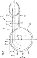
- Fig. 1 is a part of an exhaust line 1 of an internal combustion engine according to the invention shown.
- the exhaust gas line 1 has an exhaust gas turbine 3 of an exhaust gas turbocharger 2 and, viewed in the exhaust gas flow direction, arranged downstream of the exhaust gas turbine 3, connected to the exhaust gas turbine 3 exhaust pipe or exhaust gas duct element 5.
- the exhaust gas turbine 3 and the exhaust gas duct element 5 are here connected to one another by way of example by means of a flange connection.
- the exhaust gas turbine 3 and the exhaust gas duct element 5 could also be connected to one another in the same material and / or in one piece.
- an exhaust gas stream 9 coming from the internal combustion engine flows into the exhaust gas turbine 3.
- a wastegate 11 or a wastegate valve 10 of the exhaust gas turbine 3 is at least partially opened, the exhaust gas stream 9 flowing through the exhaust gas turbine 3 is split into a turbine exhaust gas stream 13 and into a wastegate exhaust gas stream 15.
- the turbine exhaust gas flow 13 flows through a turbine flow duct 17 of the exhaust gas turbine 3, by means of which the turbine exhaust gas flow 13 via a turbine wheel 19 arranged in the turbine flow duct 17 the exhaust gas turbine 3 is passed.
- the wastegate exhaust gas flow 15 in this case flows through the wastegate 11 by means of which the wastegate exhaust gas flow 15 is conducted past the turbine wheel 19 of the exhaust gas turbocharger 3.
- Fig. 5 is a section through an exhaust line 1 according to the prior art shown.
- the turbine wheel flow channel 17 and the wastegate 10 open here at an outflow side 12 of the exhaust gas turbine 3 into a large-volume mouth space 57 of the exhaust gas turbine 3. This causes, seen in the exhaust gas flow direction, downstream of the turbine wheel 19 of the exhaust gas turbocharger 3, a high exhaust gas pressure, which has a negative effect on the compression capacity of the exhaust gas turbocharger 3.
- the mouth space 57 is subdivided into a first turbine-side turbine exhaust gas flow inflow region 21 and into a second exhaust gas turbine-side waste gas flow inflow region 27 separated from the first inflow region 21.
- first inflow region 21 of the coming of the turbine 19 exhaust gas stream 13 flows.
- a discharge channel 23 of the exhaust pipe 5 adjoins the first inflow region 21, so that the turbine exhaust gas stream 13 coming from the turbine wheel 19 flows via the first inflow region 21 into the outflow channel 23.
- the exhaust gas flow 15, which is guided via the wastegate 11 flows in.
- the separation of the exhaust gas turbine side exhaust gas flow inflow region 21 from the exhaust gas side wastegate exhaust gas flow inflow region 27 takes place here by way of example by means of an intermediate wall 33 provided on the side of the opening space.
- Fig. 3 Connects to the wastegate exhaust gas flow inflow region 27 to a wastegate flow channel 25, which opens downstream of the turbine exhaust gas inflow region 21 in the adjoining this outflow channel 23 in such a way that via the wastegate 11 and the wastegate exhaust stream inflow 27th in the outflow channel 23 introduced wastegate exhaust stream 15 as a sheath flow on an inner wall 14 of the outflow channel 23 and spirally about a central longitudinal axis A A of the outflow 23 in the direction of the exhaust gas turbine 3 away through the outflow channel 23 flows.
- the exhaust gas pressure, seen in the exhaust gas flow direction, downstream of the turbine wheel 19 of the exhaust gas turbine 3 is significantly reduced.
- the wastegate flow channel 25 is formed here by way of example on the exhaust gas duct element 5.
- the mixed exhaust gas stream 16 flows here by way of example in a, seen in the exhaust gas flow direction, downstream of the exhaust gas duct element 5, connected to the exhaust gas duct element 5 exhaust line section 7 a.
- the exhaust gas line section 7 may, for example, have a plurality of exhaust gas aftertreatment elements, for example an SCR catalytic converter or a particle filter.
- the mutually associated orifices of the exhaust gas turbine side exhaust gas flow inflow region 21 and the adjoining outflow channel 23 are formed here by way of example the same or identical.
- the mutually associated orifices of the exhaust gas turbine side exhaust gas flow inflow region 21 and of the adjoining outflow channel 23 are here arranged in alignment with one another in an exemplary manner. This ensures in a particularly reliable manner that, as in Fig. 3 is shown, the coming of the turbine 19 exhaust gas stream 13 in the direction of the central longitudinal axis A A of the outflow channel 23 from the exhaust gas turbine 3 away through the outflow channel 23 flows.
- the cross-sectional area of the wastegate flow channel 25 in the region of its confluence with the outflow channel 23 here is, for example, less than the cross-sectional area of the outflow channel 23. This ensures that the flow generated by the turbine exhaust gas stream 13 and the waste gas exhaust gas flow 15 in the region of the confluence of the wastegate channel. Flow channel 25 in the discharge channel 23 have a similar speed.
- the wastegate flow channel 25 opens here, for example, at an angle into the outflow channel 23, that in the region of the mouth of the wastegate flow channel 25 in the discharge channel 23, an angle ⁇ between the flowing into the outflow channel 23 wastegate exhaust stream 15 and a Cross-sectional plane E formed by the cross-section of the outflow channel 23 in the mouth region and aligned transversely to the longitudinal axis of the outflow channel 23 in the mouth region of the wastegate flow channel 25 an angle value of only 45 °, for example.
- this angle value a particularly low exhaust gas pressure, seen in the exhaust gas flow direction, downstream of the turbine wheel 19 of the exhaust gas turbine 3 is achieved.
- the exhaust gas collection flow channel 23 here by way of example has a round cross section.
- the cross section of the exhaust gas collection flow channel 23 is also substantially constant along the exhaust gas collection flow channel 23.
- a channel section 39 forming the wastegate exhaust gas inflow region 27 has an annular cross-sectional contour, by way of example here.
- the cross-section of the channel section 39 here is essentially constant along the channel section 39 by way of example.
- a channel wall 41 delimiting the wastegate flow channel 25, for example, here continuously passes over into a channel wall 43 delimiting the channel section 39.
- the cross section of the wastegate flow duct 25 tapers as an example up to a duct section 45 of the wastegate flow duct 25.
- the duct section 45 here forms the smallest cross section of the wastegate flow channel 25.
- the channel section 45 has here for example over its entire length a constant cross-section.
- the cross-section of the channel section 45 is designed to be larger than the maximum opening cross section of the wastegate 11 or of the wastegate valve 10.
- connection channel section 47 of the wastegate flow channel 25 connects here to the channel section 45.
- a channel wall 49 delimiting the connection channel section 47 passes by way of example here continuously into the exhaust gas collection channel wall 29. This continuous transition is realized here by way of example by means of a rounding 53.
- Fig. 4 is shown schematically a cross section through the exhaust gas duct element 5.
- This illustration is intended to make clear that the wastegate flow channel 25 here adjoins tangentially and off-centerly an outer wall section 51 of the outflow channel 23, as seen in the outflow channel radial direction r, such that an outflow channel 23 enters the outlet region 23 in the mouth region of the wastegate flow channel 25 , Seen in Abströmkanal radial direction r, outer and straight trained channel wall portion 49 of the wastegate flow channel 25 at the level of an exemplary here top vertex S of the outflow channel 23 is located.
- the wastegate exhaust gas stream 15 flowing into the outflow channel 23 flows as a spiral jacket flow on the inner wall 14 of the outflow channel 23.
- the outer wall section 51 of the outflow channel 23 here continues to be continuous, for example, into the channel wall section 49 of the wastegate flow channel 25.
- the vertex S could Of course, at every other point of the outer circumference lie; In this respect, the representation here is merely exemplary and schematic.
- a central longitudinal axis A W of the wastegate flow channel 25 here, for example, in the mouth region of the wastegate flow channel 25 in the discharge channel 23 at a distance from the apex S of the discharge channel 23, the preferred and exemplary in about half a diameter d of the wastegate Flow channel 25 corresponds in the mouth area.
- an angle ⁇ between the central longitudinal axis A W of the wastegate flow channel 25 and an axis A here by way of example has an angle value of 90 °.
- the axis A passes through the vertex S and a central point Z, through which the longitudinal axis A A of the outflow channel 23 extends.
Landscapes
- Engineering & Computer Science (AREA)
- Chemical & Material Sciences (AREA)
- Mechanical Engineering (AREA)
- General Engineering & Computer Science (AREA)
- Combustion & Propulsion (AREA)
- Chemical Kinetics & Catalysis (AREA)
- Physics & Mathematics (AREA)
- Fluid Mechanics (AREA)
- General Chemical & Material Sciences (AREA)
- Supercharger (AREA)
Abstract
Description
- Die Erfindung betrifft einen Abgasstrang für eine Brennkraftmaschine nach dem Oberbegriff des Patentanspruches 1, ein Verfahren zum Betreiben des Abgasstrangs nach dem Oberbegriff des Patentanspruches 13 sowie eine Brennkraftmaschine mit dem Abgasstrang und/oder zur Durchführung des Verfahrens nach Patentanspruch 14.
- Es ist bekannt, bei einer Brennkraftmaschine einen Abgasturbolader vorzusehen. Ein derartiger Abgasturbolader weist eine in einem Abgasstrang angeordnete Abgasturbine mit einem Turbinen-Strömungskanal auf, mittels dem ein in die Abgasturbine einströmender Abgasstrom über ein Turbinenrad der Abgasturbine geleitet wird. Dadurch werden das Turbinenrad des Abgasturboladers und ein mit dem Turbinenrad verbundenes Verdichterrad des Abgasturboladers angetrieben. Mittels des Verdichterrads wird dann die der Brennkraftmaschine zugeführte Verbrennungsluft verdichtet bzw. komprimiert.
- Weiter ist es auch bekannt, an der Abgasturbine ein Wastegate bzw. ein Wastegate-Ventil vorzusehen, mittels dem zumindest ein Teil des in die Abgasturbine einströmenden Abgasstroms an dem Turbinenrad vorbeigeleitet werden kann. Mittels des Wastegate-Ventils kann beispielsweise die Verdichtung bzw. der Ladedruck der Verbrennungsluft eingestellt bzw. verstellt werden. Das Wastegate-Ventil wird dabei üblicherweise mittels einer Regel- und/oder Steuereinrichtung selbsttätig geregelt bzw. gesteuert.
- Des Weiteren münden der den Abgasstrom über das Turbinenrad führende Turbinen-Strömungskanal und das Wastegate auf einer Abströmseite der Abgasturbine in einen abgasturbinenseitigen Mündungsraum ein. Dieser Mündungsraum ist derart großvolumig ausgebildet, dass sich eine starke Quersthnittserhöhung des Turbinen-Strömungskanals und eine hochturbulente Abgasströmung in dem Mündungsraum ergibt. Diese hochturbulente Abgasströmung bewirkt, in Abgas-Strömungsrichtung gesehen, stromab des Turbinenrads der Abgasturbine einen erhöhten Abgasdruck, der sich negativ auf die Verdichtungsleistung des Abgasturboladers auswirkt.
- Aufgabe der Erfindung ist es daher, einen Abgasstrang für eine Brennkraftmaschine und ein Verfahren zum Betreiben eines Abgasstrangs bereitzustellen, bei dem die Verdichtungsleistung des Abgasturboladers auf einfache Weise erhöht ist.
- Diese Aufgabe wird durch die Merkmale der unabhängigen Ansprüche gelöst. Bevorzugte Weiterbildungen sind in den Unteransprüchen offenbart.
- Gemäß Patentanspruch 1 wird ein Abgasstrang für eine Brennkraftmaschine vorgeschlagen, mit einer in dem Abgasstrang angeordneten Abgasturbine, insbesondere einer Abgasturbine eines Abgasturboladers, wobei die ein Abgasturbinengehäuse aufweisende Abgasturbine einen Turbinen-Strömungskanal aufweist, in den ein von der Brennkraftmaschine kommender Abgasstrom einströmt und in dem ein von dem Abgasstrom antreibbares Turbinenrad der Abgasturbine angeordnet ist, wobei die Abgasturbine weiter ein Wastegate aufweist, mittels dem ein Teil des in die Abgasturbine einströmenden Abgasstroms als Wastegate-Abgasstrom an dem Turbinenrad vorbeileitbar ist, wobei der den Abgasstrom über das Turbinenrad führende Turbinen-Strömungskanal und das Wastegate auf einer Abströmseite der Abgasturbine in einen abgasturbinenseitigen Mündungsraum einmünden, und wobei an die Abströmseite der Abgasturbine ein Abströmkanal anschließt, über den ein von dem Turbinenrad kommender Abgasstrom und/oder der über das Wastegate geführte Wastegate-Abgasstrom abströmt. Erfindungsgemäß ist der abgasturbinenseitige Mündungsraum in einen ersten abgasturbinenseitigen Turbinen-Abgasstrom-Einströmbereich, in den der von dem Turbinenrad kommende Abgasstrom einströmt und an den der Abströmkanal anschließt, und in einen strömungstechnisch von dem ersten Einströmbereich getrennten, zweiten abgasturbinenseitigen Wastegate-Abgasstrom-Einströmbereich, in den der über das Wastegate geführte Abgasstrom einströmt, unterteilt. Zudem ist ein sich an den Wastegate-Abgasstrom-Einströmbereich anschließender Wastegate-Strömungskanal vorgesehen, der stromab des Turbinen-Abgasstrom-Einströmbereiches in den sich an diesen anschließenden Abströmkanal dergestalt, insbesondere tangential, einmündet, dass der über den Wastegate-Strömungskanal in den Abströmkanal eingeleitete Wastegate-Abgasstrom als Mantelströmung an der Innenwand des Abströmkanals sowie spiralförmig um eine zentrale Längsachse des Abströmkanals in Richtung von der Abgasturbine weg durch den Abströmkanal strömt.
- Dadurch wird die Verdichtungsleistung des Abgasturboladers auf einfache Weise erhöht, da durch die Unterteilung bzw. Aufteilung des Mündungsraums und durch die spiralförmige Mantelströmung des Wastegate-Abgasstroms durch den Abströmkanal der Abgasdruck, in Abgas-Strömungsrichtung gesehen, stromab des Turbinenrads deutlich verringert wird. Somit wird mittels des erfindungsgemäßen Abgasstrangs eine besonders energieeffiziente Abgasführung realisiert.
- Unter der Begrifflichkeit "Wastegate" ist jegliche Art eines an der Abgasturbine vorgesehenen Bypasskanals bzw. einer an der Abgasturbine vorgesehenen Bypassöffnung zu verstehen, mittels der der Abgasstrom an dem Turbinenrad vorbeigeleitet und die mittels einer Stelleinrichtung zumindest teilweise geöffnet und geschlossen werden kann.
- Die Stelleinrichtung kann grundsätzlich beliebig gestaltet sein. Beispielsweise kann die Stelleinrichtung derart ausgebildet sein, dass die Bypassöffnung in Abhängigkeit vom Abgasdruck im Inneren der Abgasturbine selbsttätig geöffnet und geschlossen wird. Bevorzugt ist es jedoch, wenn die Stelleinrichtung durch ein mittels einer Regel- und/oder Steuereinrichtung regelbares bzw. steuerbares Ventilelement gebildet ist, mittels dem die Bypassöffnung geöffnet und geschlossen werden kann.
- In einer bevorzugten Ausgestaltung des erfindungsgemäßen Abgasstrangs schließt sich der Abströmkanal unmittelbar an den abgasturbinenseitigen Turbinen-Abgasstrom-Einströmbereich an, dergestalt, dass der von dem Turbinenrad kommende Abgasstrom in Richtung der zentralen Längsachse des Abströmkanals von der Abgasturbine weg durch den Abströmkanal strömt. Auf diese Weise wird der Abgasdruck, in Abgas-Strömungsrichtung gesehen, stromab des Turbinenrads der Abgasturbine weiter verringert. Zudem wird auch die Vermischung des von dem Turbinenrad kommenden Abgasstroms mit dem Wastegate-Abgasstrom verbessert.
- Vorzugsweise sind die einander zugeordneten Mündungsöffnungen des abgasturbinenseitigen Turbinen-Abgasstrom-Einströmbereichs und des sich daran anschließenden Abströmkanals im Wesentlichen gleich ausgebildet, um den Abgasdruck, in Abgas-Strömungsrichtung gesehen, stromab des Turbinenrads der Abgasturbine weiter zu verringern. Bevorzugt ist dabei vorgesehen, dass die einander zugeordneten Mündungsöffnungen des abgasturbinenseitigen Turbinen-Abgasstrom-Einströmbereichs und des sich daran anschließenden Abströmkanals miteinander fluchten. Dadurch wird auf einfache und zuverlässige Weise sichergestellt, dass der von dem Turbinenrad kommende Abgasstrom in Richtung der zentralen Längsachse des Abströmkanals von der Abgasturbine weg durch den Abströmkanal strömt.
- Bevorzugt ist die Querschnittsfläche, vorzugsweise der Durchmesser, des Wastegate-Strömungskanals wenigstens im Bereich seiner Einmündung in den Abströmkanal geringer als die Querschnittsfläche, vorzugsweise der Durchmesser, des Abströmkanals. Dadurch wird erreicht, dass der von dem Turbinenrad kommende Abgasstrom und der Wastgate-Abgasstrom wenigstens im Bereich der Einmündung des Wastegate-Strömungskanals in den Abströmkanal eine ähnliche Geschwindigkeit aufweisen. Dies verringert den Abgasdruck, in Abgas-Strömungsrichtung gesehen, stromab des Turbinenrads des Abgasturboladers noch weiter.
- Weiter bevorzugt schließt der Wastegate-Strömungskanal, bezogen auf einen Querschnitt durch den Abströmkanal, tangential und/oder außermittig an einen äußeren Wandabschnitt des Abströmkanals an, vorzugsweise dergestalt, dass ein, bezogen auf den Querschnitt, äußerer und gerader mündungsseitiger Kanalwandabschnitt des Wastegate-Strömungskanals in etwa auf Höhe eines Scheitelpunkts des Abströmkanals liegt. Dadurch wird auf einfache Weise sichergestellt, dass der in den Abströmkanal eingeleitete Wastegate-Abgasstrom als spiralförmige Mantelströmung an der Innenwand des Abströmkanals strömt. Bevorzugt geht der mündungsseitige Kanalwandabschnitt des Wastegate-Strömungskanals dabei kontinuierlich, das heißt ohne Sprung, Kante oder dergleichen, in den Abströmkanal über, um eine starke Verwirbelung des in den Abströmkanal eingeleiteten Wastegate-Abgasstroms zu vermeiden.
- Bevorzugt weist eine zentrale Längsachse des Wastegate-Strömungskanals einen definierten Abstand von dem Scheitelpunkt des Abströmkanal auf, vorzugsweise einen Abstand, der in etwa einem Drittel bis zwei Drittel, vorzugsweise in etwa der Hälfte, des Durchmessers des Wastegate-Strömungskanals im Mündungsbereich des Wastegate-Strömungskanals in den Abströmkanal entspricht.
- Weiter bevorzugt mündet der Wastegate-Strömungskanal derart winklig in den Abströmkanal ein, dass ein Winkel zwischen einerseits wenigstens dem mündungsseitigen Teilbereich des Wastegate-Strömungskanals und damit dem in den Abströmkanal einströmenden Wastegate-Abgasstrom und andererseits einer durch den Querschnitt des Abströmkanals im Mündungsbereich gebildeten und/oder quer zur Längsachse des Abströmkanals im Mündungsbereich des Wastegate-Strömungskanals ausgerichteten Querschnittsebene einen Win-kelwert von 30° bis 80°, bevorzugt von 40° bis 80°, besonders bevorzugt von 45° bis 80°, aufweist. Durch diese Anwinkelung wird zuverlässig sichergestellt, dass sich der in den Abströmkanal eingeleitete Wastegate-Abgasstrom von der Abgasturbine weg durch den Abströmkanal strömt. Ein größerer Winkelwert zwischen dem Wastegate-Abgasstrom und der Querschnittsebene verringert dabei den Abgasdruck, in Abgas-Strömungsrichtung gesehen, stromab des Turbinenrads der Abgasturbine.
- In einer bevorzugten Ausgestaltung weist der Abströmkanal einen runden, insbesondere einen kreisrunden, Querschnitt auf. Auf diese Weise kann die spiralförmige Mantelströmung des in den Abströmkanal eingeleiteten Wastegate-Abgasstroms durch den Abströmkanal einfach und zuverlässig realisiert werden.
- Vorzugsweise ist der Querschnitt des Abströmkanals entlang des Abgassammel-Strömungskanals im Wesentlichen konstant, um eine harmonische Mischung des von der Turbine kommenden Abgasstroms und des Wastegate-Abgasstroms in dem Abströmkanal zu realisieren. Zudem wird dadurch der Abgasdruck, in Abgas-Strömungsrichtung gesehen, stromab des Turbinenrads der Abgasturbine weiter verringert.
- Besonders bevorzugt ist der Querschnitt des Wastegate-Strömungskanals stromab des Wastegates größer ausgebildet als der maximale Öffnungsquerschnitt der Wastegateöffnung des Wastegates. Auf diese Weise wird verhindert, dass sich der Wastegate-Abgasstrom, in Abgas-Strömungsrichtung gesehen, stromab des Wastegates in dem Wastegate-Strömungskanal staut. Eine derartige Stauung bzw. ein hoher Abgasdruck, in Abgas-Strömungsrichtung gesehen, stromab des Wastegates vermindert die Effektivität des Wastegates deutlich.
- Vorzugsweise ist der abgasturbinenseitige Turbinen-Abgasstrom-Einströmbereich auf der Abströmseite der Abgasturbine mittels wenigstens einer mündungsraumseitig vorgesehenen Zwischenwand von dem abgasturbinenseitigen Wastegate-Abgasstrom-Einströmbereich abgetrennt, um die Unterteilung des Mündungsraum zuverlässig sicherzustellen.
- In einer bevorzugten Ausgestaltung ist der Abströmkanal durch ein separates Bauteil gebildet ist, das mit der Abgasturbine bzw. mit einem Abgasturbinengehäuse verbunden ist. Dadurch weist der erfindungsgemäße Abgasstrang einen besonders einfachen Aufbau auf. Bevorzugt ist dabei vorgesehen, dass die Abgasturbine und das separate Bauteil mittels einer Flanschverbindung miteinander verbunden sind, um die Abgasturbine und das separate Bauteil auf einfache und zuverlässige Weise miteinander zu verbinden.
- Besonders bevorzugt ist der Wastegate-Strömungskanal durch das separate Bauteil gebildet, um den Aufbau des erfindungsgemäßen Abgasstrangs zu vereinfachen.
- Zur Lösung der bereits genannten Aufgabe wird ferner ein Verfahren zum Betreiben eines Abgasstrangs für eine Brennkraftmaschine vorgeschlagen, mit einer in dem Abgasstrang angeordneten Abgasturbine, insbesondere einer Abgasturbine eines Abgasturboladers, wobei die ein Abgasturbinengehäuse aufweisende Abgasturbine einen Turbinen-Strömungskanal aufweist, in den ein von der Brennkraftmaschine kommender Abgasstrom einströmt und in dem ein von dem Abgasstrom antreibbares Turbinenrad der Abgasturbine angeordnet ist, wobei die Abgasturbine weiter ein Wastegate aufweist, mittels dem ein Teil des in die Abgasturbine einströmenden Abgasstroms als Wastegate-Abgasstrom an dem Turbinenrad vorbeileitbar ist, wobei der den Abgasstrom über das Turbinenrad führende Turbinen-Strömungskanal und das Wastegate auf einer Abströmseite der Abgasturbine in einen abgasturbinenseitigen Mündungsraum einmünden, und wobei an die Abströmseite der Abgasturbine ein Abströmkanal anschließt, über den ein von dem Turbinenrad kommender Abgasstrom und/oder der über das Wastegate geführte Wastegate-Abgasstrom abströmt. Erfindungsgemäß ist der abgasturbinenseitige Mündungsraum in einen ersten abgasturbinenseitigen Turbinen-Abgasstrom-Einströmbereich, in den der von dem Turbinenrad kommende Abgasstrom einströmt und an den der Abströmkanal anschließt, und in einen strömungstechnisch von dem ersten Einströmbereich getrennten, zweiten abgasturbinenseitigen Wastegate-Abgasstrom-Einströmbereich, in den der über das Wastegate geführte Abgasstrom einströmt, unterteilt. Zudem ist ein sich an den Wastegate-Abgasstrom-Einströmbereich anschließender Wastegate-Strömungskanal vorgesehen, der stromab des Turbinen-Abgasstrom-Einströmbereiches in den sich an diesen anschließenden Abströmkanal dergestalt, insbesondere tangential, einmündet, dass der über den Wastegate-Strömungskanal in den Abströmkanal eingeleitete Wastegate-Abgasstrom als Mantelströmung an der Innenwand des Abströmkanals sowie spiralförmig um eine zentrale Längsachse des Abströmkanals in Richtung von der Abgasturbine weg durch den Abströmkanal strömt.
- Die sich durch die erfindungsgemäße Verfahrensführung ergebenden Vorteile sind identisch mit den bereits gewürdigten Vorteilen des erfindungsgemäßen Abgasstrangs, so dass diese an dieser Stelle nicht wiederholt werden.
- Des Weiteren wird auch eine Brennkraftmaschine mit dem erfindungsgemäßen Abgasstrang und/oder zur Durchführung des erfindungsgemäßen Verfahrens beansprucht. Die sich hieraus ergebenden Vorteile sind ebenfalls identisch mit den bereits gewürdigten Vorteilen des erfindungsgemäßen Abgasstrangs, so dass auch diese hier nicht wiederholt werden. Die Brennkraftmaschine kann dabei beispielsweise als Fahrzeugbrennkraftmaschine oder als stationäre Brennkraftmaschine ausgebildet sein.
- Die vorstehend erläuterten und/oder in den Unteransprüchen wiedergegebenen vorteilhaften Aus- und/oder Weiterbildungen der Erfindung können - außer zum Beispiel in den Fällen eindeutiger Abhängigkeiten oder unvereinbarer Alternativen - einzeln oder aber auch in beliebiger Kombination miteinander zur Anwendung kommen.
- Die Erfindung und ihre vorteilhaften Aus- und/oder Weiterbildungen sowie deren Vorteile werden nachfolgend anhand von Zeichnungen lediglich beispielhaft näher erläutert.
- Es zeigen:
- Fig. 1
- in einer Perspektivdarstellung einen Teil eines erfindungsgemäßen Abgasstrangs;
- Fig. 2
- in einer Schnittdarstellung einen Teil des Abgasstrangs;
- Fig. 3
- in einer schematischen Darstellung einen Teil des Abgasstrangs;
- Fig. 4
- in einer schematischen Schnittdarstellung ein Abgasstrangelement des Abgasstrangs; und
- Fig. 5
- in einer Darstellung gemäß
Fig. 2 einen Abgasstrang gemäß dem Stand der Technik. - In
Fig. 1 ist ein Teil eines erfindungsgemäßen Abgasstrangs 1 einer Brennkraftmaschine gezeigt. Der Abgasstrang 1 weist eine Abgasturbine 3 eines Abgasturboladers 2 und ein, in Abgas-Strömungsrichtung gesehen, stromab der Abgasturbine 3 angeordnetes, mit der Abgasturbine 3 verbundenes Abgasrohr bzw. Abgasstrangelement 5 auf. Die Abgasturbine 3 und das Abgasstrangelement 5 sind hier beispielhaft mittels einer Flanschverbindung miteinander verbunden. Alternativ könnten die Abgasturbine 3 und das Abgasstrangelement 5 beispielsweise aber auch materialeinheitlich und/oder einstückig miteinander verbunden sein. - Gemäß
Fig. 3 strömt beim Betrieb der Brennkraftmaschine ein von der Brennkraftmaschine kommender Abgasstrom 9 in die Abgasturbine 3 ein. Sofern ein Wastegate 11 bzw. ein Wastegate-Ventil 10 der Abgasturbine 3 zumindest teilweise geöffnet ist, wird der durch die Abgasturbine 3 strömende Abgasstrom 9 in einen Turbinenrad-Abgasstrom 13 und in einen Wastegate-Abgasstrom 15 aufgeteilt. Der Turbinenrad-Abgasstrom 13 strömt in diesem Fall durch einen Turbinen-Strömungskanal 17 der Abgasturbine 3, mittels dem der Turbinenrad-Abgasstrom 13 über ein in dem Turbinen-Strömungskanal 17 angeordnetes Turbinenrad 19 der Abgasturbine 3 geleitet wird. Der Wastegate-Abgasstrom 15 strömt in diesem Fall durch das Wastegate 11 mittels dem der Wastegate-Abgasstrom 15 an dem Turbinenrad 19 des Abgasturboladers 3 vorbeigeleitet wird. - In
Fig. 5 ist ein Schnitt durch einen Abgasstrang 1 gemäß dem Stand der Technik gezeigt. Der Turbinenrad-Strömungskanal 17 und das Wastegate 10 münden hier an einer Abströmseite 12 der Abgasturbine 3 in einen großvolumigen Mündungsraum 57 der Abgasturbine 3 ein. Dies bewirkt, in Abgas-Strömungsrichtung gesehen, stromab des Turbinenrads 19 des Abgasturboladers 3 einen hohen Abgasdruck, der sich negativ auf die Verdichtungsleistung des Abgasturboladers 3 auswirkt. - Im Gegensatz zum in
Fig. 5 gezeigten Stand der Technik ist bei dem erfindungsgemäßen Abgasstrang 1, wie inFig. 2 gezeigt ist, der Mündungsraum 57 in einen ersten abgasturbinenseitigen Turbinen-Abgasstrom-Einströmbereich 21 und in einen strömungstechnisch von dem ersten Einströmbereich 21 getrennten, zweiten abgasturbinenseitigen Wastegate-Abgasstrom-Einströmbereich 27 unterteilt. In den ersten Einströmbereich 21 strömt der von dem Turbinenrad 19 kommende Abgasstrom 13 ein. Zudem schließt an den ersten Einströmbereich 21 ein Abströmkanal 23 des Abgasrohrs 5 an, so dass der von dem Turbinenrad 19 kommende Turbinenrad-Abgastrom 13 über den ersten Einströmbereich 21 in den Abströmkanal 23 strömt. In den zweiten Einströmbereich 27 strömt der über das Wastegate 11 geführte Abgasstrom 15 ein. Die Abtrennung des abgasturbinenseitigen Turbinen-Abgasstrom-Einströmbereichs 21von dem abgasturbinenseitigen Wastegate-Abgasstrom-Einströmbereich 27 erfolgt hier beispielhaft mittels einer mündungsraumseitig vorgesehenen Zwischenwand 33. - Gemäß
Fig. 3 schließt an den Wastegate-Abgasstrom-Einströmbereich 27 ein Wastegate-Strömungskanal 25 an, der stromab des Turbinen-Abgasstrom-Einströmbereiches 21 in den sich an diesen anschließenden Abströmkanal 23 dergestalt einmündet, dass der über das Wastegate 11 und den Wastegate-Abgasstrom-Einströmbereich 27 in den Abströmkanal 23 eingeleitete Wastegate-Abgasstrom 15 als Mantelströmung an einer Innenwand 14 des Abströmkanals 23 sowie spiralförmig um eine zentrale Längsachse AA des Abströmkanals 23 in Richtung von der Abgasturbine 3 weg durch den Abströmkanal 23 strömt. Auf diese Weise wird, im Vegleich zum Stand der Technik, der Abgasdruck, in Abgas-Strömungsrichtung gesehen, stromab des Turbinenrads 19 der Abgasturbine 3 deutlich verringert. Der Wastegate-Strömungskanal 25 ist hier beispielhaft an dem Abgasstrangelement 5 ausgebildet. - In Abgas-Strömungsrichtung gesehen, stromab der Einmündung des Wastegate-Strömungskanals 25 in den Abströmkanal 23 vermischen sich der Turbinen-Abgasstrom 13 und der Wastgate-Abgasstrom 15 in dem Abströmkanal 23 zu einem Misch-Abgastrom 16. Der Misch-Abgasstrom 16 strömt hier beispielhaft in einen, in Abgas-Strömungsrichtung gesehen, stromab des Abgasstrangelements 5 angeordneten, mit dem Abgasstrangelement 5 verbundenen Abgasstrangabschnitt 7 ein. Der Abgasstrangabschnitt 7 kann beispielsweise mehrere Abgasnachbehandlungselemente, beispielsweise einen SCR-Katalysator oder einen Partikelfilter, aufweisen.
- Wie in
Fig. 2 gezeigt ist, sind die einander zugeordneten Mündungsöffnungen des abgasturbinenseitigen Turbinen-Abgasstrom-Einströmbereichs 21 und des sich daran anschließenden Abströmkanals 23 hier beispielhaft gleich bzw. identisch ausgebildet. Zudem sind die einander zugeordneten Mündungsöffnungen des abgasturbinenseitigen Turbinen-Abgasstrom-Einströmbereichs 21 und des sich daran anschließenden Abströmkanals 23 hier beispielhaft zueinander fluchtend angeordnet. Dadurch wird auf besonders zuverlässige Weise sichergestellt, dass, wie inFig. 3 gezeigt ist, der von dem Turbinenrad 19 kommende Abgasstrom 13 in Richtung der zentralen Längsachse AA des Abströmkanals 23 von der Abgasturbine 3 weg durch den Abströmkanal 23 strömt. - Weiter ist, hier lediglich beispielhaft, gemäß
Fig. 3 die Querschnittsfläche des Wastegate-Strömungskanals 25 im Bereich seiner Einmündung in den Abströmkanal 23 hier beispielhaft geringer als die Querschnittsfläche des Abströmkanals 23. Dadurch wird erreicht, dass der von dem Turbinenrad-Abgasstrom 13 und der Wastgate-Abgasstrom 15 im Bereich der Einmündung des Wastegate-Strömungskanals 25 in den Abströmkanal 23 eine ähnliche Geschwindigkeit aufweisen. - Wie in
Fig. 3 weiter gezeigt ist, mündet der Wastegate-Strömungskanal 25 hier beispielhaft derart winklig in den Abströmkanal 23 ein, dass im Bereich der Mündung des Wastegate-Strömungskanals 25 in den Abströmkanal 23 ein Winkel α zwischen dem in den Abströmkanal 23 einströmenden Wastegate-Abgasstrom 15 und einer durch den Querschnitt des Abströmkanals 23 im Mündungsbereich gebildeten und quer zur Längsachse des Abströmkanals 23 im Mündungsbereich des Wastegate-Strömungskanals 25 ausgerichteten Querschnittsebene E einen Winkelwert von hier lediglich beispielsweise 45° aufweist. Durch diesen Winkelwert wird ein besonders geringer Abgasdruck, in Abgas-Strömungsrichtung gesehen, stromab des Turbinenrads 19 der Abgasturbine 3 erreicht. - Weiter weist der Abgassammel-Strömungskanal 23 hier beispielhaft einen runden Querschnitt auf. Der Querschnitt des Abgassammel-Strömungskanals 23 ist hier zudem entlang des Abgassammel-Strömungskanals 23 im Wesentlichen konstant.
- Wie in
Fig. 2 gezeigt ist, weist ein den Wastegate-Abgasstrom-Einströmbereich 27 bildender Kanalabschnitt 39 hier beispielhaft eine ringförmige Querschnittskontur auf. Zudem ist der Querschnitt des Kanalabschnitts 39 hier beispielhaft entlang des Kanalabschnitts 39 im Wesentlichen konstant. Des Weiteren geht eine den Wastegate-Strömungskanal 25 begrenzende Kanalwand 41 hier beispielhaft kontinuierlich in eine den Kanalabschnitt 39 begrenzende Kanalwand 43 über. In Abgas-Strömungsrichtung gesehen, stromab eines Verbindungsbereichs 44, an dem die Abgasturbine 3 und das Abgasstrangelement 5 miteinander verbunden sind, verjüngt sich hier beispielhaft der Querschnitt des Wastegate-Strömungskanals 25 bis hin zu einem Kanalabschnitt 45 des Wastegate-Strömungskanals 25. Der Kanalabschnitt 45 bildet hier den geringsten Querschnitt des Wastegate-Strömungskanal 25 aus. Der Kanalabschnitt 45 weist hier beispielhaft über seine gesamte Länge einen konstanten Querschnitt auf. Der Querschnitt des Kanalabschnitts 45 ist hier beispielhaft größer ausgebildet als der maximale Öffnungsquerschnitt Wastegates 11 bzw. des Wastegate-Ventils 10. - Weiter schließt hier an den Kanalabschnitt 45 ein Anschluss-Kanalabschnitt 47 des Wastegate-Strömungskanals 25 an. Eine den Anschluss-Kanalabschnitt 47 begrenzende Kanalwand 49 geht hier beispielhaft kontinuierlich in die Abgassammel-Kanalwand 29 über. Dieser kontinuierliche Übergang ist hier beispielhaft mittels einer Verrundung 53 realisiert.
- In
Fig. 4 ist schematisch ein Querschnitt durch das Abgasstrangelement 5 gezeigt. Diese Darstellung soll verdeutlichen, dass sich der Wastegate-Strömungskanal 25 hier tangential und außermittig an einen, in Abströmkanal-Radialrichtung r gesehen, äußeren Wandabschnitt 51 des Abströmkanals 23 anschließt, dergestalt, dass in dem Mündungsbereich des Wastegate-Strömungskanals 25 in den Abströmkanal 23 ein, in Abströmkanal-Radialrichtung r gesehen, äußerer und gerade ausgebildeter Kanalwandabschnitt 49 des Wastegate-Strömungskanals 25 auf Höhe eines hier beispielhaft oberen Scheitelpunkts S des Abströmkanals 23 liegt. Dadurch wird auf besonders zuverlässige Weise sichergestellt, dass der in den Abströmkanal 23 einströmende Wastegate-Abgasstrom 15 als spiralförmige Mantelströmung an der Innenwand 14 des Abströmkanals 23 strömt. Zudem geht der äußeren Wandabschnitt 51 des Abströmkanals 23 hier beispielhaft auch kontinuierlich in den Kanalwandabschnitt 49 des Wastegate-Strömungskanals 25 über. Der Scheitelpunkt S könnte selbstverständlich auch an jeder anderen Stelle des Außenumfangs liegen; insofern ist die Darstellung hier lediglich beispielhaft und schematisch zu verstehen. - Des Weiteren weist eine zentrale Längsachse AW des Wastegate-Strömungskanals 25 hier beispielhaft im Mündungsbereich des Wastegate-Strömungskanals 25 in den Abströmkanal 23 einen Abstand von dem Scheitelpunkt S des Abströmkanals 23 auf, der bevorzugt und beispielhaft in etwa der Hälfte eines Durchmessers d des Wastegate-Strömungskanals 25 in dem Mündungsbereich entspricht. Zudem weist ein Winkel β zwischen der zentralen Längsachse AW des Wastegate-Strömungskanals 25 und einer Achse A hier beispielhaft einen Winkelwert von 90° auf. Die Achse A verläuft durch den Scheitelpunkt S und einen zentralen Punkt Z, durch den die Längsachse AA des Abströmkanals 23 verläuft.
-
- 1
- Abgasstrang
- 2
- Abgasturbolader
- 3
- Abgasturbine
- 5
- Abgasstrangelement
- 7
- Abgasstrangabschnitt
- 9
- Abgasstrom
- 10
- Wastegate
- 11
- Wastegate-Ventil
- 12
- Abströmseite
- 13
- Turbinenrad-Abgasstrom
- 14
- Innenwand
- 15
- Wastegate-Abgasstrom
- 16
- Misch-Abgasstrom
- 17
- Turbinen-Strömungskanal
- 19
- Turbinenrad
- 21
- Turbinen-Abgasstrom-Einströmbereich
- 23
- Abströmkanal
- 25
- Wastegate-Strömungskanal
- 27
- Wastegate-Abgasstrom-Einströmbereich
- 33
- Zwischenwand
- 39
- Kanalabschnitt
- 41
- Kanalwand
- 43
- Kanalwand
- 44
- Verbindungsbereich
- 45
- Kanalabschnitt
- 47
- Anschluss-Kanalabschnitt
- 49
- Kanalwand
- 51
- Wandabschnitt
- 53
- Verrundung
- 57
- Mündungsraum
- A
- Achse
- AA
- zentrale Längsachse Abströmkanal
- AW
- zentrale Längsachse Wastegate-Strömungskanal
- d
- Durchmesser
- E
- Querschnittsebene
- Z
- zentraler Punkt
- α
- Winkel
- β
- Winkel
Claims (14)
- Abgasstrang für eine Brennkraftmaschine, mit einer in dem Abgasstrang angeordneten Abgasturbine (3), insbesondere einer Abgasturbine eines Abgasturboladers,
wobei die ein Abgasturbinengehäuse aufweisende Abgasturbine (3) einen Turbinen-Strömungskanal (17) aufweist, in den ein von der Brennkraftmaschine kommender Abgasstrom (9) einströmt und in dem ein von dem Abgasstrom (9) antreibbares Turbinenrad (19) der Abgasturbine (3) angeordnet ist,
wobei die Abgasturbine (3) weiter ein Wastegate (11) aufweist, mittels dem ein Teil des in die Abgasturbine (3) einströmenden Abgasstroms (9) als Wastegate-Abgasstrom (15) an dem Turbinenrad (19) vorbeileitbar ist,
wobei der den Abgasstrom (9) über das Turbinenrad (19) führende Turbinen-Strömungskanal (17) und das Wastegate (11) auf einer Abströmseite (12) der Abgasturbine (3) in einen abgasturbinenseitigen Mündungsraum (57) einmünden, und wobei an die Abströmseite (12) der Abgasturbine (3) ein Abströmkanal (23) anschließt, über den ein von dem Turbinenrad (19) kommender Abgasstrom (13) und/oder der über das Wastegate (11) geführte Wastegate-Abgasstrom (15) abströmt,
dadurch gekennzeichnet,
dass der abgasturbinenseitige Mündungsraum (57) in einen ersten abgasturbinenseitigen Turbinen-Abgasstrom-Einströmbereich (21), in den der von dem Turbinenrad (19) kommende Abgasstrom (13) einströmt und an den der Abströmkanal (23) anschließt, und in einen strömungstechnisch von dem ersten Einströmbereich (21) getrennten, zweiten abgasturbinenseitigen Wastegate-Abgasstrom-Einströmbereich (27), in den der über das Wastegate (11) geführte Abgasstrom (15) einströmt, unterteilt ist, und
dass ein sich an den Wastegate-Abgasstrom-Einströmbereich (27) anschließender Wastegate-Strömungskanal (25) vorgesehen ist, der stromab des Turbinen-Abgasstrom-Einströmbereiches (21) in den sich an diesen anschließenden Abströmkanal (23) dergestalt, insbesondere tangential, einmündet, dass der über den Wastegate-Strömungskanal (25) in den Abströmkanal (23) eingeleitete Wastegate-Abgasstrom (15) als Mantelströmung an der Innenwand (14) des Abströmkanals (23) sowie spiralförmig um eine zentrale Längsachse (AA) des Abströmkanals (23) in Richtung von der Abgasturbine (3) weg durch den Abströmkanal (23) strömt. - Abgasstrang nach Anspruch 1, dadurch gekennzeichnet, dass sich der Abströmkanal (23) unmittelbar an den abgasturbinenseitigen Turbinen-Abgasstrom-Einströmbereich (21) anschließt, dergestalt, dass der von dem Turbinenrad (19) kommende Abgasstrom (13) in Richtung der zentralen Längsachse (AA) des Abströmkanals (23) von der Abgasturbine (3) weg durch den Abströmkanal (23) strömt.
- Abgasstrang Anspruch 2, dadurch gekennzeichnet, dass die einander zugeordneten Mündungsöffnungen des abgasturbinenseitigen Turbinen-Abgasstrom-Einströmbereichs (21) und des sich daran anschließenden Abströmkanals (23) im Wesentlichen gleich ausgebildet sind, wobei bevorzugt vorgesehen ist, dass die einander zugeordneten Mündungsöffnungen des abgasturbinenseitigen Turbinen-Abgasstrom-Einströmbereichs (21) und des sich daran anschließenden Abströmkanals (23) zueinander fluchtend angeordnet sind.
- Abgasstrang nach einem der vorhergehenden Ansprüche, dadurch gekennzeichnet, dass die Querschnittsfläche, vorzugsweise der Durchmesser, des Wastegate-Strömungskanals (25) wenigstens im Bereich seiner Einmündung in den Abströmkanal (23) geringer ist als die Querschnittsfläche, vorzugsweise der Durchmesser, des Abströmkanals (23).
- Abgasstrang nach einem der vorhergehenden Ansprüche, dadurch gekennzeichnet, dass der Wastegate-Strömungskanal (25), bezogen auf einen Querschnitt durch den Abströmkanal (23), tangential und/oder außermittig an einen äußeren Wandabschnitt (51) des Abströmkanals (23) anschließt, vorzugsweise dergestalt, dass ein, bezogen auf den Querschnitt, äußerer und gerade ausgebildeter mündungsseitiger Kanalwandabschnitt (49) des Wastegate-Strömungskanals (25) in etwa auf Höhe eines Scheitelpunkts (S) des Abströmkanals (23) liegt und, vorzugsweise kontinuierlich in diesen übergeht.
- Abgasstrang nach Anspruch 4 und 5, dadurch gekennzeichnet, dass eine zentrale Längsachse (AW) des Wastegate-Strömungskanals (25) einen definierten Abstand von dem Scheitelpunkt (S) des Abströmkanals (23) aufweist, vorzugsweise einen Abstand aufweist, der in etwa einem Drittel bis zwei Drittel, vorzugsweise in etwa der Hälfte, des Durchmessers des Wastegate-Strömungskanals (25) im Mündungsbereich des Wastegate-Strömungskanals (25) in den Abströmkanal (23) entspricht.
- Abgasstrang nach einem der vorhergehenden Ansprüche, dadurch gekennzeichnet, dass der Wastegate-Strömungskanal (25) derart winklig in den Abströmkanal (23) einmündet, dass ein Winkel (α) zwischen einerseits wenigstens dem mündungsseitigen Teilbereich des Wastegate-Strömungskanals (25) und damit dem in den Abströmkanal (23) einströmenden Wastegate-Abgasstrom (15) und andererseits einer durch den Querschnitt des Abströmkanals (23) im Mündungsbereich gebildeten und/oder quer zur Längsachse (AW) des Abströmkanals (23) im Mündungsbereich des Wastegate-Strömungskanals (25) ausgerichteten Querschnittsebene (E) einen Winkelwert von 30° bis 80°, bevorzugt von 40° bis 80°, besonders bevorzugt von 45° bis 80°, aufweist.
- Abgasstrang nach einem der vorhergehenden Ansprüche, dadurch gekennzeichnet, dass der Abströmkanal (23) einen runden, insbesondere eine kreisrunden, Querschnitt aufweist
- Abgasstrang nach einem der vorhergehenden Ansprüche, dadurch gekennzeichnet, dass der Querschnitt des Abströmkanals (23) entlang des Abströmkanals (23) im Wesentlichen konstant ist.
- Abgasstrang nach einem der vorhergehenden Ansprüche, dadurch gekennzeichnet, dass der Querschnitt des Wastegate-Strömungskanals (25) stromab des Wastegates (11) größer ausgebildet ist als der maximale Öffnungsquerschnitt der Wastegateöffnung des Wastegates (11).
- Abgasstrang nach einem der vorhergehenden Ansprüche, dadurch gekennzeichnet, dass der abgasturbinenseitige Turbinen-Abgasstrom-Einströmbereich (21) auf der Abströmseite (12) der Abgasturbine (3) mittels wenigstens einer mündungsraumseitig vorgesehenen Zwischenwand (33) von dem abgasturbinenseitigen Wastegate-Abgasstrom-Einströmbereich (27) abgetrennt ist.
- Abgasstrang nach einem der vorhergehenden Ansprüche, dadurch gekennzeichnet, dass der Abströmkanal (23) durch ein separates Bauteil gebildet ist, das mit der Abgasturbine (3) bzw. mit einem Abgasturbinengehäuse verbunden ist, vorzugsweise mittels einer Flanschverbindung verbunden ist.
- Verfahren zum Betreiben eines Abgasstrangs für eine Brennkraftmaschine, insbesonder zum Betreiben eines Abgasstrangs nach einem der vorhergehenden Ansprüche, mit einer in dem Abgasstrang angeordneten Abgasturbine (3), insbesondere einer Abgasturbine eines Abgasturboladers,
wobei die ein Abgasturbinengehäuse aufweisende Abgasturbine (3) einen Turbinen-Strömungskanal (17) aufweist, in den ein von der Brennkraftmaschine kommender Abgasstrom (9) einströmt und in dem ein von dem Abgasstrom (9) antreibbares Turbinenrad (19) der Abgasturbine (3) angeordnet ist,
wobei die Abgasturbine (3) weiter ein Wastegate (11) aufweist, mittels dem ein Teil des in die Abgasturbine (3) einströmenden Abgasstroms (9) als Wastegate-Abgasstrom (15) an dem Turbinenrad (17) vorbeileitbar ist,
wobei der den Abgasstrom (9) über das Turbinenrad (17) führende Turbinen-Strömungskanal (17) und das Wastegate (11) auf einer Abströmseite (12) der Abgasturbine (3) in einen abgasturbinenseitigen Mündungsraum (57) einmünden, und wobei an die Abströmseite der Abgasturbine (3) ein Abströmkanal (23) anschließt, über den ein von dem Turbinenrad (19) kommender Abgasstrom (13) und/oder der über das Wastegate (11) geführte Wastegate-Abgasstrom (15) abströmt,
dadurch gekennzeichnet,
dass der abgasturbinenseitige Mündungsraum (57) in einen ersten abgasturbinenseitigen Turbinen-Abgasstrom-Einströmbereich (21), in den der von dem Turbinenrad (19) kommende Abgasstrom (13) einströmt und an den der Abströmkanal (23) anschließt, und in einen strömungstechnisch von dem ersten Einströmbereich (21) getrennten, zweiten abgasturbinenseitigen Wastegate-Abgasstrom-Einströmbereich (27), in den der über das Wastegate (11) geführte Abgasstrom einströmt, unterteilt ist, und
dass ein sich an den Wastegate-Abgasstrom-Einströmbereich (27) anschließender Wastegate-Strömungskanal (25) vorgesehen ist, der stromab des Turbinen-Abgasstrom-Einströmbereiches (21) in den sich an diesen anschließenden Abströmkanal (23) dergestalt, insbesondere tangential, einmündet, dass der über den Wastegate-Strömungskanal (25) in den Abströmkanal (23) eingeleitete Wastegate-Abgasstrom (15) als Mantelströmung an der Innenwand (14) des Abströmkanals (23) sowie spiralförmig um eine zentrale Längsachse (AA) des Abströmkanals (23) in Richtung von der Abgasturbine (3) weg durch den Abströmkanal (23) strömt. - Brennkraftmaschine mit einem Abgasstrang nach einem der Ansprüche 1 bis 12 und/oder zur Durchführung eines Verfahrens nach Anspruch 13.
Applications Claiming Priority (1)
| Application Number | Priority Date | Filing Date | Title |
|---|---|---|---|
| DE102015007414.8A DE102015007414A1 (de) | 2015-06-06 | 2015-06-06 | Abgasstrang für eine Brennkraftmaschine |
Publications (2)
| Publication Number | Publication Date |
|---|---|
| EP3101248A1 true EP3101248A1 (de) | 2016-12-07 |
| EP3101248B1 EP3101248B1 (de) | 2020-04-22 |
Family
ID=56203074
Family Applications (1)
| Application Number | Title | Priority Date | Filing Date |
|---|---|---|---|
| EP16001186.2A Active EP3101248B1 (de) | 2015-06-06 | 2016-05-24 | Abgasstrang für eine brennkraftmaschine |
Country Status (6)
| Country | Link |
|---|---|
| US (1) | US20160356207A1 (de) |
| EP (1) | EP3101248B1 (de) |
| CN (1) | CN106246349A (de) |
| BR (1) | BR102016012786B1 (de) |
| DE (1) | DE102015007414A1 (de) |
| RU (1) | RU2722555C2 (de) |
Citations (3)
| Publication number | Priority date | Publication date | Assignee | Title |
|---|---|---|---|---|
| WO1989007194A1 (fr) * | 1988-02-02 | 1989-08-10 | Audi Ag | Turbine pour turbocompresseur |
| DE19549020A1 (de) * | 1994-12-28 | 1996-07-11 | Aisin Seiki | Abgasregeleinrichtung für einen Turbolader |
| DE102007021763A1 (de) * | 2006-05-11 | 2007-11-15 | Toyota Jidosha Kabushiki Kaisha, Toyota | Verbrennungsmotor |
Family Cites Families (16)
| Publication number | Priority date | Publication date | Assignee | Title |
|---|---|---|---|---|
| US3994620A (en) * | 1975-06-30 | 1976-11-30 | Wallace-Murray Corporation | Variable exducer turbine control |
| FR2483515A1 (fr) * | 1980-05-27 | 1981-12-04 | Renault | Dispositif antipollution pour moteur a combustion interne a turbocompresseur |
| DE3101131A1 (de) * | 1981-01-15 | 1982-08-05 | Aktiengesellschaft Kühnle, Kopp & Kausch, 6710 Frankenthal | Abgasturbolader und verfahren zur wirkungsgradverbesserung |
| US5118455A (en) * | 1990-03-29 | 1992-06-02 | Loren Norman S | Gas assisted injection molding |
| JP3624521B2 (ja) * | 1996-02-29 | 2005-03-02 | アイシン精機株式会社 | ターボチャージャ |
| US6202413B1 (en) * | 1999-02-04 | 2001-03-20 | Cummins Engine Company, Inc. | Multiple nozzle ejector for wastegated turbomachinery |
| US6978615B2 (en) * | 2003-06-09 | 2005-12-27 | Jones Gregg A | High efficiency turbocharger having secondary wastegate volute |
| US8387385B2 (en) * | 2004-08-31 | 2013-03-05 | The United States Of America, As Represented By The Administrator Of The U.S. Environmental Protection Agency | Efficient bypass valve for multi-stage turbocharging system |
| DE102006001571A1 (de) * | 2006-01-12 | 2007-08-02 | Robert Bosch Gmbh | Strömungsoptimierter Bypass für Strömungsmaschinen |
| WO2010104695A2 (en) * | 2009-03-09 | 2010-09-16 | Borgwarner Inc. | Exhaust-gas turbocharger |
| WO2011111118A1 (ja) * | 2010-03-12 | 2011-09-15 | トヨタ自動車株式会社 | 内燃機関の排気浄化システム |
| DE102010044683A1 (de) * | 2010-09-08 | 2012-03-08 | Volkswagen Ag | Abgasturbolader mit einem Bypassventil |
| JP5858143B2 (ja) * | 2012-03-30 | 2016-02-10 | トヨタ自動車株式会社 | 内燃機関の制御装置 |
| US9103271B2 (en) * | 2013-04-04 | 2015-08-11 | Ford Global Technologies, Llc | Exhaust leakage management |
| JP2015014258A (ja) * | 2013-07-05 | 2015-01-22 | 株式会社Ihi | 過給機 |
| GB2528097A (en) * | 2014-07-09 | 2016-01-13 | Jaguar Land Rover Ltd | Wastegate valve |
-
2015
- 2015-06-06 DE DE102015007414.8A patent/DE102015007414A1/de not_active Withdrawn
-
2016
- 2016-05-24 EP EP16001186.2A patent/EP3101248B1/de active Active
- 2016-06-03 RU RU2016122052A patent/RU2722555C2/ru active
- 2016-06-03 BR BR102016012786-6A patent/BR102016012786B1/pt active IP Right Grant
- 2016-06-06 CN CN201610391453.0A patent/CN106246349A/zh active Pending
- 2016-06-06 US US15/174,294 patent/US20160356207A1/en not_active Abandoned
Patent Citations (3)
| Publication number | Priority date | Publication date | Assignee | Title |
|---|---|---|---|---|
| WO1989007194A1 (fr) * | 1988-02-02 | 1989-08-10 | Audi Ag | Turbine pour turbocompresseur |
| DE19549020A1 (de) * | 1994-12-28 | 1996-07-11 | Aisin Seiki | Abgasregeleinrichtung für einen Turbolader |
| DE102007021763A1 (de) * | 2006-05-11 | 2007-11-15 | Toyota Jidosha Kabushiki Kaisha, Toyota | Verbrennungsmotor |
Also Published As
| Publication number | Publication date |
|---|---|
| RU2016122052A (ru) | 2017-12-07 |
| US20160356207A1 (en) | 2016-12-08 |
| CN106246349A (zh) | 2016-12-21 |
| DE102015007414A1 (de) | 2016-12-08 |
| BR102016012786A2 (pt) | 2016-12-06 |
| BR102016012786B1 (pt) | 2023-01-24 |
| RU2722555C2 (ru) | 2020-06-01 |
| EP3101248B1 (de) | 2020-04-22 |
| RU2016122052A3 (de) | 2019-10-15 |
Similar Documents
| Publication | Publication Date | Title |
|---|---|---|
| EP3051099B1 (de) | Verdichter mit variabler anströmgeometrie | |
| EP3018311B1 (de) | Injektionsabschnitt für eine abgasnachbehandlungseinrichtung | |
| DE112012005379B4 (de) | Fliehkraftabscheider und Filteranordnung | |
| EP2137397B1 (de) | Verbrennungsluft- und abgasanordnung eines verbrennungsmotors | |
| EP2532408B2 (de) | Luftfilter mit vorabscheider | |
| WO2009068181A1 (de) | Turbolader | |
| EP3092385B1 (de) | Trimmsteller für mindestens einen verdichter und brennkraftmaschine | |
| DE102015209704A1 (de) | Verdichter mit variabler Anströmgeometrie | |
| EP2025896A2 (de) | Radialverdichter für einen Turbolader | |
| WO2010031499A1 (de) | Radialverdichter, insbesondere für einen abgasturbolader einer brennkraftmaschine | |
| DE102011122322A1 (de) | Fliehkraftabscheider und Filteranordnung | |
| DE102010036799A1 (de) | Abgasrückführungsvorrichtung für einen Verbrennungsmotor | |
| DE102012014333A1 (de) | Mischvorrichtung zur Nachbehandlung von Abgasen | |
| DE102010051638A1 (de) | Gasturbinenbrennkammer mit einer Kühlluftzuführvorrichtung | |
| EP1881173B1 (de) | Multidiffusor für eine Hubkolbenbrennkraftmaschine, sowie Hubkolbenbrennkraftmaschine | |
| EP3274569A1 (de) | Mischvorrichtung | |
| EP3234337A1 (de) | Luftleitung für einen ansaugtrakt einer verbrennungskraftmaschine, insbesondere eines kraftwagens | |
| EP2788591A1 (de) | Turbine für einen abgasturbolader | |
| DE102020129001B4 (de) | Abgasanlage mit Abgasturbolader, Ejektor und Abgaskatalysator | |
| DE102013001231B4 (de) | Abgasführung einer Abgasnutzturbine für ein Turbocompound-System und Turbocompound-System | |
| DE102004039299A1 (de) | Turboverdichter für eine Brennkraftmaschine | |
| EP2225467B1 (de) | Drallerzeugungsapparat und turbolader mit einem solchen drallerzeugungsapparat | |
| EP3101248B1 (de) | Abgasstrang für eine brennkraftmaschine | |
| DE102005042720A1 (de) | Verfahren und Vorrichtung zur Partikelabscheidung aus Gasen | |
| EP2387468B1 (de) | Zyklonabscheider mit einlassströmungsleitrohr |
Legal Events
| Date | Code | Title | Description |
|---|---|---|---|
| PUAI | Public reference made under article 153(3) epc to a published international application that has entered the european phase |
Free format text: ORIGINAL CODE: 0009012 |
|
| STAA | Information on the status of an ep patent application or granted ep patent |
Free format text: STATUS: THE APPLICATION HAS BEEN PUBLISHED |
|
| AK | Designated contracting states |
Kind code of ref document: A1 Designated state(s): AL AT BE BG CH CY CZ DE DK EE ES FI FR GB GR HR HU IE IS IT LI LT LU LV MC MK MT NL NO PL PT RO RS SE SI SK SM TR |
|
| AX | Request for extension of the european patent |
Extension state: BA ME |
|
| STAA | Information on the status of an ep patent application or granted ep patent |
Free format text: STATUS: REQUEST FOR EXAMINATION WAS MADE |
|
| 17P | Request for examination filed |
Effective date: 20170607 |
|
| RBV | Designated contracting states (corrected) |
Designated state(s): AL AT BE BG CH CY CZ DE DK EE ES FI FR GB GR HR HU IE IS IT LI LT LU LV MC MK MT NL NO PL PT RO RS SE SI SK SM TR |
|
| STAA | Information on the status of an ep patent application or granted ep patent |
Free format text: STATUS: EXAMINATION IS IN PROGRESS |
|
| 17Q | First examination report despatched |
Effective date: 20190212 |
|
| RAP1 | Party data changed (applicant data changed or rights of an application transferred) |
Owner name: MAN TRUCK & BUS SE |
|
| GRAP | Despatch of communication of intention to grant a patent |
Free format text: ORIGINAL CODE: EPIDOSNIGR1 |
|
| STAA | Information on the status of an ep patent application or granted ep patent |
Free format text: STATUS: GRANT OF PATENT IS INTENDED |
|
| RIC1 | Information provided on ipc code assigned before grant |
Ipc: F15D 1/04 20060101ALI20191008BHEP Ipc: F02B 37/18 20060101AFI20191008BHEP Ipc: B01F 5/00 20060101ALI20191008BHEP Ipc: B01F 3/02 20060101ALI20191008BHEP Ipc: F01N 13/08 20100101ALI20191008BHEP |
|
| INTG | Intention to grant announced |
Effective date: 20191113 |
|
| GRAS | Grant fee paid |
Free format text: ORIGINAL CODE: EPIDOSNIGR3 |
|
| GRAA | (expected) grant |
Free format text: ORIGINAL CODE: 0009210 |
|
| STAA | Information on the status of an ep patent application or granted ep patent |
Free format text: STATUS: THE PATENT HAS BEEN GRANTED |
|
| AK | Designated contracting states |
Kind code of ref document: B1 Designated state(s): AL AT BE BG CH CY CZ DE DK EE ES FI FR GB GR HR HU IE IS IT LI LT LU LV MC MK MT NL NO PL PT RO RS SE SI SK SM TR |
|
| REG | Reference to a national code |
Ref country code: CH Ref legal event code: EP |
|
| REG | Reference to a national code |
Ref country code: IE Ref legal event code: FG4D Free format text: LANGUAGE OF EP DOCUMENT: GERMAN |
|
| REG | Reference to a national code |
Ref country code: DE Ref legal event code: R096 Ref document number: 502016009607 Country of ref document: DE |
|
| REG | Reference to a national code |
Ref country code: AT Ref legal event code: REF Ref document number: 1260374 Country of ref document: AT Kind code of ref document: T Effective date: 20200515 |
|
| REG | Reference to a national code |
Ref country code: NL Ref legal event code: FP |
|
| REG | Reference to a national code |
Ref country code: SE Ref legal event code: TRGR |
|
| REG | Reference to a national code |
Ref country code: LT Ref legal event code: MG4D |
|
| PG25 | Lapsed in a contracting state [announced via postgrant information from national office to epo] |
Ref country code: LT Free format text: LAPSE BECAUSE OF FAILURE TO SUBMIT A TRANSLATION OF THE DESCRIPTION OR TO PAY THE FEE WITHIN THE PRESCRIBED TIME-LIMIT Effective date: 20200422 Ref country code: GR Free format text: LAPSE BECAUSE OF FAILURE TO SUBMIT A TRANSLATION OF THE DESCRIPTION OR TO PAY THE FEE WITHIN THE PRESCRIBED TIME-LIMIT Effective date: 20200723 Ref country code: NO Free format text: LAPSE BECAUSE OF FAILURE TO SUBMIT A TRANSLATION OF THE DESCRIPTION OR TO PAY THE FEE WITHIN THE PRESCRIBED TIME-LIMIT Effective date: 20200722 Ref country code: IS Free format text: LAPSE BECAUSE OF FAILURE TO SUBMIT A TRANSLATION OF THE DESCRIPTION OR TO PAY THE FEE WITHIN THE PRESCRIBED TIME-LIMIT Effective date: 20200822 Ref country code: FI Free format text: LAPSE BECAUSE OF FAILURE TO SUBMIT A TRANSLATION OF THE DESCRIPTION OR TO PAY THE FEE WITHIN THE PRESCRIBED TIME-LIMIT Effective date: 20200422 Ref country code: PT Free format text: LAPSE BECAUSE OF FAILURE TO SUBMIT A TRANSLATION OF THE DESCRIPTION OR TO PAY THE FEE WITHIN THE PRESCRIBED TIME-LIMIT Effective date: 20200824 |
|
| PG25 | Lapsed in a contracting state [announced via postgrant information from national office to epo] |
Ref country code: RS Free format text: LAPSE BECAUSE OF FAILURE TO SUBMIT A TRANSLATION OF THE DESCRIPTION OR TO PAY THE FEE WITHIN THE PRESCRIBED TIME-LIMIT Effective date: 20200422 Ref country code: HR Free format text: LAPSE BECAUSE OF FAILURE TO SUBMIT A TRANSLATION OF THE DESCRIPTION OR TO PAY THE FEE WITHIN THE PRESCRIBED TIME-LIMIT Effective date: 20200422 Ref country code: LV Free format text: LAPSE BECAUSE OF FAILURE TO SUBMIT A TRANSLATION OF THE DESCRIPTION OR TO PAY THE FEE WITHIN THE PRESCRIBED TIME-LIMIT Effective date: 20200422 Ref country code: BG Free format text: LAPSE BECAUSE OF FAILURE TO SUBMIT A TRANSLATION OF THE DESCRIPTION OR TO PAY THE FEE WITHIN THE PRESCRIBED TIME-LIMIT Effective date: 20200722 |
|
| PG25 | Lapsed in a contracting state [announced via postgrant information from national office to epo] |
Ref country code: AL Free format text: LAPSE BECAUSE OF FAILURE TO SUBMIT A TRANSLATION OF THE DESCRIPTION OR TO PAY THE FEE WITHIN THE PRESCRIBED TIME-LIMIT Effective date: 20200422 |
|
| REG | Reference to a national code |
Ref country code: DE Ref legal event code: R097 Ref document number: 502016009607 Country of ref document: DE |
|
| PG25 | Lapsed in a contracting state [announced via postgrant information from national office to epo] |
Ref country code: RO Free format text: LAPSE BECAUSE OF FAILURE TO SUBMIT A TRANSLATION OF THE DESCRIPTION OR TO PAY THE FEE WITHIN THE PRESCRIBED TIME-LIMIT Effective date: 20200422 Ref country code: MC Free format text: LAPSE BECAUSE OF FAILURE TO SUBMIT A TRANSLATION OF THE DESCRIPTION OR TO PAY THE FEE WITHIN THE PRESCRIBED TIME-LIMIT Effective date: 20200422 Ref country code: LI Free format text: LAPSE BECAUSE OF NON-PAYMENT OF DUE FEES Effective date: 20200531 Ref country code: ES Free format text: LAPSE BECAUSE OF FAILURE TO SUBMIT A TRANSLATION OF THE DESCRIPTION OR TO PAY THE FEE WITHIN THE PRESCRIBED TIME-LIMIT Effective date: 20200422 Ref country code: DK Free format text: LAPSE BECAUSE OF FAILURE TO SUBMIT A TRANSLATION OF THE DESCRIPTION OR TO PAY THE FEE WITHIN THE PRESCRIBED TIME-LIMIT Effective date: 20200422 Ref country code: SM Free format text: LAPSE BECAUSE OF FAILURE TO SUBMIT A TRANSLATION OF THE DESCRIPTION OR TO PAY THE FEE WITHIN THE PRESCRIBED TIME-LIMIT Effective date: 20200422 Ref country code: EE Free format text: LAPSE BECAUSE OF FAILURE TO SUBMIT A TRANSLATION OF THE DESCRIPTION OR TO PAY THE FEE WITHIN THE PRESCRIBED TIME-LIMIT Effective date: 20200422 Ref country code: CH Free format text: LAPSE BECAUSE OF NON-PAYMENT OF DUE FEES Effective date: 20200531 Ref country code: CZ Free format text: LAPSE BECAUSE OF FAILURE TO SUBMIT A TRANSLATION OF THE DESCRIPTION OR TO PAY THE FEE WITHIN THE PRESCRIBED TIME-LIMIT Effective date: 20200422 |
|
| PG25 | Lapsed in a contracting state [announced via postgrant information from national office to epo] |
Ref country code: SK Free format text: LAPSE BECAUSE OF FAILURE TO SUBMIT A TRANSLATION OF THE DESCRIPTION OR TO PAY THE FEE WITHIN THE PRESCRIBED TIME-LIMIT Effective date: 20200422 Ref country code: PL Free format text: LAPSE BECAUSE OF FAILURE TO SUBMIT A TRANSLATION OF THE DESCRIPTION OR TO PAY THE FEE WITHIN THE PRESCRIBED TIME-LIMIT Effective date: 20200422 |
|
| PLBE | No opposition filed within time limit |
Free format text: ORIGINAL CODE: 0009261 |
|
| STAA | Information on the status of an ep patent application or granted ep patent |
Free format text: STATUS: NO OPPOSITION FILED WITHIN TIME LIMIT |
|
| REG | Reference to a national code |
Ref country code: BE Ref legal event code: MM Effective date: 20200531 |
|
| 26N | No opposition filed |
Effective date: 20210125 |
|
| GBPC | Gb: european patent ceased through non-payment of renewal fee |
Effective date: 20200722 |
|
| PG25 | Lapsed in a contracting state [announced via postgrant information from national office to epo] |
Ref country code: LU Free format text: LAPSE BECAUSE OF NON-PAYMENT OF DUE FEES Effective date: 20200524 |
|
| PG25 | Lapsed in a contracting state [announced via postgrant information from national office to epo] |
Ref country code: GB Free format text: LAPSE BECAUSE OF NON-PAYMENT OF DUE FEES Effective date: 20200722 Ref country code: IE Free format text: LAPSE BECAUSE OF NON-PAYMENT OF DUE FEES Effective date: 20200524 |
|
| PG25 | Lapsed in a contracting state [announced via postgrant information from national office to epo] |
Ref country code: BE Free format text: LAPSE BECAUSE OF NON-PAYMENT OF DUE FEES Effective date: 20200531 Ref country code: SI Free format text: LAPSE BECAUSE OF FAILURE TO SUBMIT A TRANSLATION OF THE DESCRIPTION OR TO PAY THE FEE WITHIN THE PRESCRIBED TIME-LIMIT Effective date: 20200422 |
|
| PG25 | Lapsed in a contracting state [announced via postgrant information from national office to epo] |
Ref country code: TR Free format text: LAPSE BECAUSE OF FAILURE TO SUBMIT A TRANSLATION OF THE DESCRIPTION OR TO PAY THE FEE WITHIN THE PRESCRIBED TIME-LIMIT Effective date: 20200422 Ref country code: MT Free format text: LAPSE BECAUSE OF FAILURE TO SUBMIT A TRANSLATION OF THE DESCRIPTION OR TO PAY THE FEE WITHIN THE PRESCRIBED TIME-LIMIT Effective date: 20200422 Ref country code: CY Free format text: LAPSE BECAUSE OF FAILURE TO SUBMIT A TRANSLATION OF THE DESCRIPTION OR TO PAY THE FEE WITHIN THE PRESCRIBED TIME-LIMIT Effective date: 20200422 |
|
| PG25 | Lapsed in a contracting state [announced via postgrant information from national office to epo] |
Ref country code: MK Free format text: LAPSE BECAUSE OF FAILURE TO SUBMIT A TRANSLATION OF THE DESCRIPTION OR TO PAY THE FEE WITHIN THE PRESCRIBED TIME-LIMIT Effective date: 20200422 |
|
| REG | Reference to a national code |
Ref country code: AT Ref legal event code: MM01 Ref document number: 1260374 Country of ref document: AT Kind code of ref document: T Effective date: 20210524 |
|
| PG25 | Lapsed in a contracting state [announced via postgrant information from national office to epo] |
Ref country code: AT Free format text: LAPSE BECAUSE OF NON-PAYMENT OF DUE FEES Effective date: 20210524 |
|
| PGFP | Annual fee paid to national office [announced via postgrant information from national office to epo] |
Ref country code: NL Payment date: 20250526 Year of fee payment: 10 |
|
| PGFP | Annual fee paid to national office [announced via postgrant information from national office to epo] |
Ref country code: DE Payment date: 20250528 Year of fee payment: 10 |
|
| PGFP | Annual fee paid to national office [announced via postgrant information from national office to epo] |
Ref country code: IT Payment date: 20250522 Year of fee payment: 10 |
|
| PGFP | Annual fee paid to national office [announced via postgrant information from national office to epo] |
Ref country code: FR Payment date: 20250526 Year of fee payment: 10 |
|
| PGFP | Annual fee paid to national office [announced via postgrant information from national office to epo] |
Ref country code: SE Payment date: 20250526 Year of fee payment: 10 |