EP3100928B1 - Vehicle with a support system - Google Patents
Vehicle with a support system Download PDFInfo
- Publication number
- EP3100928B1 EP3100928B1 EP16172001.6A EP16172001A EP3100928B1 EP 3100928 B1 EP3100928 B1 EP 3100928B1 EP 16172001 A EP16172001 A EP 16172001A EP 3100928 B1 EP3100928 B1 EP 3100928B1
- Authority
- EP
- European Patent Office
- Prior art keywords
- rail
- stop
- vehicle
- underfloor
- carrier
- Prior art date
- Legal status (The legal status is an assumption and is not a legal conclusion. Google has not performed a legal analysis and makes no representation as to the accuracy of the status listed.)
- Active
Links
Images

Classifications
-
- B—PERFORMING OPERATIONS; TRANSPORTING
- B61—RAILWAYS
- B61C—LOCOMOTIVES; MOTOR RAILCARS
- B61C17/00—Arrangement or disposition of parts; Details or accessories not otherwise provided for; Use of control gear and control systems
- B61C17/06—Power storing devices
-
- B—PERFORMING OPERATIONS; TRANSPORTING
- B61—RAILWAYS
- B61C—LOCOMOTIVES; MOTOR RAILCARS
- B61C17/00—Arrangement or disposition of parts; Details or accessories not otherwise provided for; Use of control gear and control systems
-
- Y—GENERAL TAGGING OF NEW TECHNOLOGICAL DEVELOPMENTS; GENERAL TAGGING OF CROSS-SECTIONAL TECHNOLOGIES SPANNING OVER SEVERAL SECTIONS OF THE IPC; TECHNICAL SUBJECTS COVERED BY FORMER USPC CROSS-REFERENCE ART COLLECTIONS [XRACs] AND DIGESTS
- Y02—TECHNOLOGIES OR APPLICATIONS FOR MITIGATION OR ADAPTATION AGAINST CLIMATE CHANGE
- Y02T—CLIMATE CHANGE MITIGATION TECHNOLOGIES RELATED TO TRANSPORTATION
- Y02T30/00—Transportation of goods or passengers via railways, e.g. energy recovery or reducing air resistance
Definitions
- the present invention relates to a vehicle, in particular a rail vehicle, with a support system for mounting a replaceable component on an underfloor area of the vehicle. Furthermore, the invention relates to a method for installing and / or removal of such a replaceable component of the vehicle.
- an underfloor area of vehicles such as buses, trucks or rail vehicles, is used to place different functional components there.
- trucks containers for fuel are mounted on an underfloor area of the vehicle frame.
- the document WO 2012/095596 A1 describes a vehicle, in particular a rail vehicle, with a support system for attaching a replaceable component to an underfloor area of the vehicle, the support system having a receptacle for the component and an extendable support for supporting the receptacle at the underfloor area, and wherein the support at least a first and a second rail, wherein the first rail is fixed to a support structure of the underfloor region, and the second rail is supported directly or indirectly on the first rail slidably, and the receiving device is attached to the second rail.
- the battery can have a high weight, it is provided according to the prior art to connect the working platform with the flap of the underbody compartment positively. In this way it is effectively prevented that during maintenance or replacement of the battery the control over the same is lost and the battery is lost for example falls to the ground.
- the positioning of the platform is necessary for each maintenance of the battery in order to be able to pull the battery out of the underbody compartment.
- Object of the present invention is therefore to provide a support system for mounting a replaceable component to an underfloor area of a vehicle, in particular a rail vehicle, which has a simple and robust construction.
- maintenance and replacement of such a component should be simplified.
- the vehicle has a support system, wherein the support system comprises a receiving device for the component and an extendable support device for supporting the receiving device at the underfloor area.
- this support system has a first and a second rail, wherein a stop device is effectively provided between a rail and the underfloor area or between the rails, which can assume a blocking position and an unlocking position.
- the receiving device is attached to the second rail, wherein the second rail is in turn supported directly or indirectly on the first rail slidably.
- the rails mesh directly with one another and transmit supporting forces via direct component contact.
- the rails may each have interlocking S-profiles.
- the first rail which supports the second rail directly or indirectly, attached to a support structure of the underfloor area of the vehicle. This allows the Recording device drawer-like pulled out of the underfloor area of the vehicle in a pull-out and inserted by means of an insertion movement.
- the stop device serves to limit in cooperation with a first rail stop a displacement of the rails to each other in the pull-out direction.
- the stopper device is in a locking position and activated, whereby the effectiveness of the support of the rails is secured together.
- the described design of the vehicle with support system for the first time makes it possible to make the component accessible for maintenance or replacement purposes in a highly efficient manner and at the same time to ensure that falling out is prevented and thus the risk of injury of the maintenance personnel is reduced. If the replacement of the component is necessary, the receiving device can be completely removed in a simple manner by deactivating the stop device.
- the carrying device has at least one third rail, wherein the second rail is supported displaceably directly or indirectly via the third rail with respect to the first rail.
- the third rail may be arranged between the first and second rail such that the second rail is completely displaceable over the first rail, and in the extended state, there is no overlap between the first and second rail. In this way, the receiving device and the component provided therein or thereto can be pulled out particularly far.
- the number of rails used in the support device can be adapted according to the requirements of the support device.
- the scope should therefore not be limited to a support device with two or three rails, but a use of a support device with four or more rails - with appropriate adjustment - conceivable.
- a subfloor compartment is provided in the underfloor area, which is designed such that the receiving device can be inserted into this and pulled out.
- an outer side of the receiving device is formed corresponding to a panel of the vehicle, so that the inserted receiving device forms a substantially homogeneous surface together with the trim of the vehicle.
- the vehicle trim in the region of the underbody compartment can have a suitable flap arrangement from which the receiving device can be pulled out.
- the invention proposes that the support system has return means, whereby the abutment device of the support device is activated by the insertion movement or is brought into the locked position.
- the return means is thus arranged such that the Antschvorcardischimum is deactivated or in the unlocked position - is activated when the receiving device is pushed back or pushed into the underfloor area.
- the stop device is basically activated, or blocking position is.
- the safety for maintenance personnel is considerably increased, because it is never possible that the recording device unintentionally beyond the stop device and thus completely pulled out and could fall down.
- the stop device has a stop element.
- the stop device further comprises a biasing means acting on the stop element. If the stop device is activated, then the stop element is acted upon by the biasing means with a biasing force, or the biasing force of the biasing means is increased relative to the biasing force in the unlocked position.
- the stop element Upon reaching a fixed, maximum displacement of the rails to each other, the stop element automatically engages with the first rail stop and blocks further pulling apart of the rails.
- the first rail stop and the stop device are designed so that the stop element engages in the rail stop. This means that the maintenance personnel can pull out the receiving device until the rail stop and Stop element engage with each other in operative engagement and thus the movement of the pulling apart is stopped.
- a suitable stop can be provided in the underfloor area or in the underfloor compartment, which comes into operative engagement with the stop element and thus limits a movement in the pull-out direction.
- the first rail stop and / or the stop element has unlocking means which are effectively arranged counter to the pull-out direction.
- unlocking means and the stop element are designed such that the stop element can be disengaged by an insertion movement of the carrying device by means of the unlocking means.
- the unlocking means have at least one inclined surface, which - based on a wedge effect - can push the stop element back and disengage when the receiving device is pushed back.
- the concrete configuration of the unlocking should have no limiting effect: For example, an oblique surface - or an effective-like arrangement - be provided on the rail stop, on the stop element or as another component.
- the carrying device has a second rail stop, with which the stop element in the inserted state of the receiving device can be brought into engagement.
- an insertion movement of the receiving device can be limited, in which the stop element of the stop device is in operative engagement with the second rail stop upon reaching a certain insertion position.
- the stop device is designed and arranged on a rail, and further provided on another rail a recess such that the stop element is at least partially receivable in the inserted state of the support device of the recess. Recess and stop device are thus provided so that the stop element the stop device can rest in the recess. This reduces the load on the biasing means.
- the stop element thus engages in the recess, wherein the stop element does not necessarily have to have a limiting effect with a stop.
- In the foreground here is the effect that the biasing means are at least partially relieved in the inserted position of the receiving device, and thereby their life is increased.
- the recess and / or the stop element are provided with unlocking means. These act in the pull-out of the receiving device and have, for example, an inclined surface, which is achieved by the pull-out of the engagement of the stop element in the recess.
- the stop element of the stop device may be designed as a pin, which is accommodated in a receptacle of the stop device according to its longitudinal axis displaceable.
- the bolt projects beyond the receptacle of the stop device according to its longitudinal direction and is thus suitable in a rail stop, designed for example as a bore, intervene. If the stop device is deactivated, then a suitable mechanism of the stop device causes the pin to be at least partially withdrawn into a receptacle of the stop device and no longer protruding beyond it. In this condition, the bolt will not be able to engage a rail stop.
- the stop device is preferably designed such that the longitudinal axis of the bolt extends substantially perpendicular to the withdrawal direction of the support system.
- the bolt of the stop device can be mounted spring-loaded in the receptacle of the stop device displaced. Thereby, the bolt can be inserted against the biasing force against the biasing direction in the stop device even when activated stop device.
- a rail stop is designed as a bore in a rail.
- the bore is arranged in the rail so that it can at least partially receive the part of the bolt which projects beyond the stop device.
- a ramp-like inclined surface is provided in the pull-out direction and / or in the direction of the insertion movement in a rail. These oblique surface connects substantially in a continuous shape a bottom of the bore and a surface of the rail. Furthermore, the surface is inclined so that upon extension or retraction of the support system of the bolt of the activated stop device is inserted into the receptacle of the stopper device against the bias by a part of an end face of the bolt slides along the surface.
- the bolt is in at least partially inserted position in the receptacle of the stop device before.
- the rails are arranged adjacent to each other, so that the bolt of the stop device is pressed by a surface of a rail against the biasing direction in the recording of the stop device. If the support system now reaches an end position - pushed in completely or pulled out - the rail stop executed as a bore aligns with the bolt of the stop device. This spring-loaded jumps into the bore of the rail stop and blocks further disengagement or pushing together of the support system.
- the bolt rests - essentially unloaded - in the bore of the second rail stop. Further insertion of the support system is thereby prevented by a radial wall of the bore with a radial outer side of the bolt is engaged, and so a positive connection between the rails is made against the pull-out.
- a pull-out side of the bore is provided with the inclined surface which pushes the bolt into the receptacle of the stop device, if the support system is pulled out.
- an analogous embodiment of the unlocking means for the first rail stop is disclosed. Accordingly, a radial side of the bore of the first rail stop is present in the pull-out direction and an inclined surface is provided on the bore in the direction of the insertion movement.
- the inclined surface in the bore of the first rail stop and / or the second rail stop is designed so that it merges into a bottom of the holes substantially seamlessly.
- the pin When the stopper device is deactivated, the pin is substantially completely retracted into the receptacle of the stopper device. In this state, a positive connection between the bolt and a radial wall of a bore of a rail stop is not present, so that the rails can be completely pulled apart.
- the receiving device or the second or the third rail has means for fastening an engagement element for engaging the external lifting device.
- the replacement or inspection of components of the receiving device is substantially facilitated.
- batteries are arranged in the receiving device, for example, they have a high weight.
- the receiving device including batteries can be transported to and from a test stand or workbench without much difficulty.
- Conceivable is the use of a forklift.
- the engagement elements may be formed according to the fork of the forklift.
- the engagement elements are mounted to the receiving device - for example by means of screws - when it has already been pulled out of the underfloor area of the vehicle. This has the advantage that the entire volume of the corresponding underfloor area can be used exclusively for the receiving device and no extra space for the engagement elements must be reserved.
- One or more of the embodiments of the described supporting system of a vehicle are particularly advantageous if the component to be replaced or checked is a battery unit of an electrically driven vehicle. It has been shown that these battery units must be regularly maintained and replaced, since they are subjected to increased stress during operation, for example, to buffer regenerated braking energy. In particular, battery units have a high weight, making their handling during maintenance and replacement is particularly demanding. The design of the receiving device of the battery unit in the sense of the described support system, the maintenance and replacement of the battery unit is considerably simplified.
- the receiving device is designed like a drawer.
- a support device is provided on each of two vertical sides of the receiving device, with which the receiving device is mounted in the underbody of the vehicle.
- a method for removing a replaceable component, for example a battery unit, of a vehicle is also cited.
- the vehicle has a carrying device according to one of the preceding described embodiments and the method comprises the following steps:
- the pickup device which carries the component to be replaced, is pulled out of the underbody compartment of the underfloor area of the vehicle.
- the component to be replaced is a battery unit of a rail vehicle.
- the rail vehicle is driven to a workshop, where the appropriate personnel can carry out the inspection and possible replacement of the battery unit.
- At least one engagement element is fastened to the receiving device or to the second or third rail.
- These engagement elements can be either hooks or eyes for a crane device or also suitable receptacles for lifting devices, for example for a forklift. Since the engagement element is not mounted in the inserted state of the receiving device, it is necessary that this is kept in the workshop.
- the lifting or crane device is effectively positioned on the engagement element.
- the weight of the receiving device can be essentially carried by the lifting or crane device, so that in the following step, the stop device can be deactivated.
- the support system is in a state in which the receiving device can be completely separated from the vehicle.
- the operator brings the stop device in the unlocked position and pulls the receiving device so far from the underfloor area of the vehicle that the rails go out of engagement and the receiving device is supported exclusively by the external lifting or crane device.
- a check or replacement of the corresponding component in the receiving device can be performed by the receiving device is transported by means of the lifting or crane device to the designated work or storage space.
- existing mechanical or electrical means for connecting the component to the vehicle must be interrupted at the latest before the removal of the receiving device. If the receiving device carries a battery unit, the electrical connection of the battery unit with other electrical components of the vehicle is interrupted before removal of the same.
- the receiving device is brought by means of the lifting or crane device in a suitable installation position in front of the underbody compartment of the underfloor area of the vehicle.
- the rail of the pickup device is brought into engagement with a rail of the underbody compartment, so that the carrier device can divert the weight of the pickup device into the underfloor area of the vehicle.
- the engagement element is removed. After further electrical and / or mechanical connections between the component and the vehicle have been made, the receiving device or the support system can be completely inserted into the underbody compartment.
- a complete method of replacing a component of a vehicle is disclosed by first sequentially applying the above-described method of disassembling a component and the subsequent, previously described, method of installing a component of a vehicle.
- the maintenance and optionally the replacement of a component of a vehicle can be carried out particularly simply and quickly.
- the described embodiments are not intended to be limiting to the invention and are in each case in a suitable form combined to form further favorable embodiments.
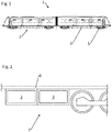
- FIG. 1 A typical rail vehicle 1 with an underfloor area 2 and subfloors 3 provided thereon is in Fig. 1 shown.
- Such a rail vehicle 1 has numerous electrical components, which may be arranged partly on the vehicle roof, as well as on the underfloor area 2 in subfloor compartments 3.
- Fig. 2 is a schematic representation of a section of the underfloor region 2 of the rail vehicle 1 from Fig. 1 , Under the floor 6 of the rail vehicle 1 there are a wheel set 5 and subfloors 3. In these subfloors 3, for example, at least battery unit 4, which are supported by a support system 10.
- Fig. 3a to 3d describe a first embodiment of the support system 10.
- Fig. 3a is a receiving device 15 in a fully inserted state.
- the entire support system 10 comprising the support device 11 and the Receiving device 15, in which the battery unit 4 is arranged, completely absorbed by the lower shelf 3 and covered by the bottom 6.
- Fig. 3b shows the support device 10 with an almost completely pulled in the withdrawal direction A receiving device 15.
- the second rail 13 is provided fixed, the second rail 13 slidably on the third rail 14, and the third rail 14 in turn slidably on the first rail 12 is stored. If the receiving device 15 is pulled out of the underbody compartment 3, this is done by a relative displacement of the second rail 13 and third rail 14 with respect to the first rail 12.
- Fig. 3c illustrates the fully extended state of the recording device 15th
- a stop device 16 is connected to the second rail 13 or the receiving device 15 and can be activated or deactivated.
- the stopper 16 is in the Fig. 3a to 3c in each case in a blocking position, ie the stop device 16 is activated.
- the stop device 16 comprises a stop element 17, which is biased in the direction of the blocking position.
- the biasing device not shown, causes the stop member 17 of the stopper 16 in the activated state always strives to go with a first rail stop 18 in operative engagement. This condition is in Fig.
- the stop device 14 is brought into the unlocked position.
- the stop element 17 of the stop device 16 now deactivated assumes a position at which the stop element 17 is no longer in operative engagement with the first rail stop 18 is.
- the receiving device 15 can now be removed from the third rail 14.
- a lifting device 31 is previously brought under the receiving device 15.
- a plurality of engagement elements 30 have previously been mounted on the receiving device 15, with corresponding mounting devices being provided on the receiving device 15 for this purpose. It is conceivable that the engagement elements 30 are formed as receptacles for a fork of a forklift 31, which are screwed to an underside of the receiving device 15.
- the in this embodiment ( Fig. 3d Lifting device 31 designed as a forklift truck completely carries the receiving device 15, which can thus be transported to a workbench, for example.
- the second rail 13 of the receiving device 15 is brought into a position in which the second rail 13 is aligned with the third rail 14.
- the return means 20 is of particular importance.
- the restoring means 20 are arranged in the underbody compartment 3 or on the underfloor region 2 such that they change the switching position of the abutment device 16 during the insertion movement.
- the stop device 16 is always switched to the blocking position, provided that it was in the unlocked position.
- the return means 20 are such that they have an oblique upper side - directional information refers to the orientation of the sheet of the Fig. 3 - Touch the deactivated stop member 17 at the insertion movement E and press down, causing the stopper 16 assumes the blocking position. This ensures that the stop device 16 is always activated when the receiving device 15 is inserted into the underbody compartment 3. This prevents that when pulling out the receiving device 15 in the pull-out direction A this is moved beyond the maximum displacement and fell in the worst case to the ground and thus involved personnel could be injured.
- the stopper 16 acts with the first rail stop 18 exclusively in the withdrawal direction A.
- the stopper 16 is equipped with unlocking means 21, which are formed in the present embodiment as an inclined surface on the stop element 17. Since the prestressed stop element 17 endeavors to remain in operative engagement with the first rail stop 18, the preload force must be overcome for unlocking.
- the insertion movement E is translated via the inclined surface of the stop element 17 in a vertical movement, whereby the stop member 17, at least in the short term, against the bias, out of engagement with the first rail stop 18.
- the stop member 17 of the stopper 16 rests in an activated state in a recess 22 of a second rail stop 19. In this way, biasing means of the stopper 16 are in a relatively relaxed state, creating the risk of Breakage of the biasing agent is reduced.
- the second rail stop 19 can be designed so that the insertion movement E is limited in cooperation with the stop element 17.
- the second rail stop 19 may be attached both to the first rail 12 and to the underbody compartment 3.
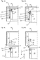
- FIG. 4a to Fig. 4d introduce a further embodiment of the support device 10.
- the underbody 3 is shown together with the support device 10 in a horizontal plan view.
- the withdrawal takes place in the withdrawal direction A and the insertion movement E of the receiving device 15 analogous to the embodiment described above.
- the stop member 17 of the stopper 16 has a different arrangement to the previous embodiment, wherein a maximum displacement V max is also defined by the first rail stop 18 in cooperation with the activated stop member 17 (see Fig. 4c) ,
- Fig. 4d shows the decoupled receiving device 15 with the stop device 16 deactivated. Since the stop element 17 of the stop device 16 located in the unlocking position can not be in operative engagement with the first rail stop 18, For example, the second rail 13 of the receiving device 15 can be pulled out of the overlap with the third rail 14. The receiving device 15 is thus free and can be moved to another location.
- the receiving device 15 can according to the Fig. 4c to 4a be completely inserted into the underbody 3.
- There are return means 20 are provided, which activate the deactivated stop device 16 during insertion and can bring into blocking position.
Description
Die vorliegende Erfindung betrifft ein Fahrzeug, insbesondere ein Schienenfahrzeug, mit einem Tragsystem zur Anbringung einer austauschbaren Komponente an einem Unterflurbereich des Fahrzeugs. Weiterhin betrifft die Erfindung ein Verfahren zum Ein- und/oder Ausbau einer solchen austauschbaren Komponente des Fahrzeugs.The present invention relates to a vehicle, in particular a rail vehicle, with a support system for mounting a replaceable component on an underfloor area of the vehicle. Furthermore, the invention relates to a method for installing and / or removal of such a replaceable component of the vehicle.
Im Allgemeinen ist bekannt, dass ein Unterflurbereich von Fahrzeugen, wie zum Beispiel von Bussen, Lastkraftwagen oder Schienenfahrzeugen, dazu genutzt wird, unterschiedliche funktionale Komponenten dort anzuordnen. Beispielsweise sind bei Lastkraftwagen Behältnisse für Kraftstoff an einem Unterflurbereich des Fahrzeugrahmens montiert.In general, it is known that an underfloor area of vehicles, such as buses, trucks or rail vehicles, is used to place different functional components there. For example, in trucks containers for fuel are mounted on an underfloor area of the vehicle frame.
Weiterhin können am Unterflurbereich, insbesondere in sogenannten Unterbodenfächern von Fahrzeugen elektrische Komponenten, zum Beispiel Umrichter, Klimageräte, Schaltungen oder auch elektrische Energiespeicher vorgesehen sein. Um ein fehlerfreies Funktionieren solcher Komponenten sicherzustellen, sind regelmäßige Wartung und gegebenenfalls ein Austausch von Komponenten notwendig.Furthermore, it is possible to provide electrical components, for example converters, air conditioning units, circuits or also electrical energy storage devices, in the underfloor area, in particular in so-called underfloor compartments of vehicles. In order to ensure a faultless functioning of such components, regular maintenance and, if necessary, replacement of components are necessary.
Aus der europäischen Patentschrift
Das Dokument
Da die Batterie ein hohes Gewicht aufweisen kann, ist gemäß dem Stand der Technik vorgesehen, die Arbeitsbühne mit der Klappe des Unterbodenfachs formschlüssig zu verbinden. Auf diese Weise wird effektiv verhindert, dass während der Wartung oder des Austausches der Batterie die Kontrolle über selbige verloren geht und die Batterie beispielsweise zu Boden fällt.Since the battery can have a high weight, it is provided according to the prior art to connect the working platform with the flap of the underbody compartment positively. In this way it is effectively prevented that during maintenance or replacement of the battery the control over the same is lost and the battery is lost for example falls to the ground.
Um gemäß der Lehre des Stands der Technik Austausch und Wartung der Komponente zu erleichtern, ist ein technisches System von nicht unerheblicher Komplexität notwendig. Sowohl die Lagerung der Batterie in dem Unterbodenfach, als auch die Abstützung der Batterie außerhalb auf einer Arbeitsbühne erfordert eine hohe Anzahl zusätzlicher Bauteile.In order to facilitate replacement and maintenance of the component according to the teachings of the prior art, a technical system of considerable complexity is necessary. Both the storage of the battery in the underbody compartment, as well as the support of the battery outside on a working platform requires a large number of additional components.
Weiterhin ist für jede Wartung der Batterie die Positionierung der Arbeitsbühne notwendig, um die Batterie aus dem Unterbodenfach herausziehen zu können.Furthermore, the positioning of the platform is necessary for each maintenance of the battery in order to be able to pull the battery out of the underbody compartment.
Aufgabe der vorliegenden Erfindung ist es daher, ein Tragsystem zur Anbringung einer austauschbaren Komponente an einem Unterflurbereich eines Fahrzeugs, insbesondere eines Schienenfahrzeugs, bereitzustellen, welches einen einfachen und robusten Aufbau aufweist. Zudem sollen Wartung und Austausch einer solchen Komponente vereinfacht werden.Object of the present invention is therefore to provide a support system for mounting a replaceable component to an underfloor area of a vehicle, in particular a rail vehicle, which has a simple and robust construction. In addition, maintenance and replacement of such a component should be simplified.
Die obige Aufgabe wird durch ein Fahrzeug nach Anspruch 1 gelöst. Dabei weist das Fahrzeug ein Tragsystem auf, wobei das Tragsystem eine Aufnahmevorrichtung für die Komponente und eine ausziehbare Tragvorrichtung zum Abstützen der Aufnahmevorrichtung am Unterflurbereich umfasst. Dieses Tragsystem weist gemäß einer Ausführungsform eine erste und eine zweite Schiene auf, wobei zwischen einer Schiene und dem Unterflurbereich oder zwischen den Schienen eine Anschlagvorrichtung wirksam vorgesehen ist, die eine Sperrstellung und eine Entsperrstellung einnehmen kann.The above object is achieved by a vehicle according to
Die Aufnahmevorrichtung ist an der zweiten Schiene befestigt, wobei die zweite Schiene wiederum direkt oder indirekt an der ersten Schiene verschiebbar abgestützt ist. Denkbar ist, dass die Schienen direkt ineinandergreifen und über direktem Bauteilkontakt Abstützungskräfte übertragen. Dazu können die Schienen jeweils ineinander greifende S-Profile aufweisen. Um die Verschiebung der Schienen zueinander zu erleichtern, ist dabei die Verwendung von Wälzmitteln zwischen den Schienen als vorteilhaft zu betrachten. Weiterhin ist die erste Schiene, welche die zweite Schiene direkt oder indirekt trägt, an einer Tragstruktur des Unterflurbereichs des Fahrzeugs befestigt. Dadurch kann die Aufnahmevorrichtung schubladenartig aus dem Unterflurbereich des Fahrzeugs in einer Ausziehrichtung herausgezogen und mittels einer Einschubbewegung eingeschoben werden.The receiving device is attached to the second rail, wherein the second rail is in turn supported directly or indirectly on the first rail slidably. It is conceivable that the rails mesh directly with one another and transmit supporting forces via direct component contact. For this purpose, the rails may each have interlocking S-profiles. In order to facilitate the displacement of the rails to each other, the use of rolling elements between the rails is to be considered advantageous. Furthermore, the first rail, which supports the second rail directly or indirectly, attached to a support structure of the underfloor area of the vehicle. This allows the Recording device drawer-like pulled out of the underfloor area of the vehicle in a pull-out and inserted by means of an insertion movement.
Die Anschlagvorrichtung dient dazu, in Zusammenwirken mit einem ersten Schienenanschlag eine Verschiebung der Schienen zueinander in Ausziehrichtung zu begrenzen. In diesem Fall ist die Anschlagvorrichtung in einer Sperrstellung befindlich und aktiviert, wobei die Wirksamkeit der Abstützung der Schienen aneinander sichergestellt ist.The stop device serves to limit in cooperation with a first rail stop a displacement of the rails to each other in the pull-out direction. In this case, the stopper device is in a locking position and activated, whereby the effectiveness of the support of the rails is secured together.
Wird die Anschlagvorrichtung in Entsperrstellung gebracht, so wird die Begrenzung der Verschiebung der Schienen zueinander in Ausziehrichtung aufgehoben und die Anschlagvorrichtung ist deaktiviert. In diesem Zustand können beide Schienen vollständig auseinander gezogen und getrennt werden.If the stop device is brought into the unlocked position, the limitation of the displacement of the rails relative to one another in the pull-out direction is canceled and the stop device is deactivated. In this condition, both rails can be completely pulled apart and separated.
Durch die beschriebene Ausbildung des Fahrzeugs mit Tragsystem wird erstmalig ermöglicht, in hocheffizienter Weise die Komponente zu Wartungs- oder Austauschzwecken zugänglich zu machen und gleichzeitig sicherzustellen, dass ein Herausfallen verhindert und somit das Verletzungsrisiko des Wartungspersonals verringert wird. Ist der Austausch der Komponente notwendig kann in einfacher Art und Weise die Aufnahmevorrichtung vollständig entnommen werden, indem die Anschlagvorrichtung deaktiviert wird.The described design of the vehicle with support system for the first time makes it possible to make the component accessible for maintenance or replacement purposes in a highly efficient manner and at the same time to ensure that falling out is prevented and thus the risk of injury of the maintenance personnel is reduced. If the replacement of the component is necessary, the receiving device can be completely removed in a simple manner by deactivating the stop device.
Gemäß einer Ausführungsform weist die Tragvorrichtung mindestens eine dritte Schiene auf, wobei die zweite Schiene direkt oder indirekt über die dritte Schiene gegenüber der ersten Schiene verschiebbar abgestützt ist. Die dritte Schiene kann derart zwischen der ersten und zweiten Schiene angeordnet sein, sodass die zweite Schiene vollständig über die erste Schiene heraus verschiebbar ist, und im ausgezogenen Zustand keine Überdeckung zwischen erster und zweiter Schiene vorliegt. Auf diese Weise kann die Aufnahmevorrichtung und die darin oder daran vorgesehene Komponente besonders weit herausgezogen werden.According to one embodiment, the carrying device has at least one third rail, wherein the second rail is supported displaceably directly or indirectly via the third rail with respect to the first rail. The third rail may be arranged between the first and second rail such that the second rail is completely displaceable over the first rail, and in the extended state, there is no overlap between the first and second rail. In this way, the receiving device and the component provided therein or thereto can be pulled out particularly far.
Grundsätzlich ist die Anzahl der verwendeten Schienen der Tragvorrichtung entsprechend den Anforderungen an die Tragvorrichtung anpassbar. Der Schutzbereich soll somit nicht auf eine Tragvorrichtung mit zwei oder drei Schienen begrenzt sein, sondern eine Verwendung einer Tragvorrichtung mit vier oder mehr Schienen ist - bei entsprechender Anpassung - denkbar.In principle, the number of rails used in the support device can be adapted according to the requirements of the support device. The scope should therefore not be limited to a support device with two or three rails, but a use of a support device with four or more rails - with appropriate adjustment - conceivable.
Günstigerweise ist im Unterflurbereich ein Unterbodenfach vorgesehen, welches derart gestaltet ist, dass die Aufnahmevorrichtung in dieses eingeschoben und herausgezogen werden kann.Conveniently, a subfloor compartment is provided in the underfloor area, which is designed such that the receiving device can be inserted into this and pulled out.
Gemäß einer Ausführungsform ist eine Außenseite der Aufnahmevorrichtung entsprechend einer Verkleidung des Fahrzeugs ausgebildet, sodass die eingeschobene Aufnahmevorrichtung zusammen mit der Verkleidung des Fahrzeugs eine im Wesentlichen homogene Oberfläche bildet. Anstatt eine solche blendenartige Verkleidung für die Aufnahmevorrichtung vorzusehen kann die Fahrzeugverkleidung im Bereich des Unterbodenfachs eine geeignete Klappenanordnung aufweisen, aus welcher die Aufnahmevorrichtung herausgezogen werden kann.According to one embodiment, an outer side of the receiving device is formed corresponding to a panel of the vehicle, so that the inserted receiving device forms a substantially homogeneous surface together with the trim of the vehicle. Instead of providing such an aperture-like covering for the receiving device, the vehicle trim in the region of the underbody compartment can have a suitable flap arrangement from which the receiving device can be pulled out.
In Erweiterung dieses Grundprinzips wird erfindungsgemäß vorgeschlagen, dass das Tragsystem Rückstellmittel aufweist, wodurch die Anschlagvorrichtung der Tragvorrichtung durch die Einschubbewegung aktiviert wird bzw. in Sperrstellung gebracht wird. Das Rückstellmittel ist folglich derart angeordnet, dass die Anschlagvorrichtungsofern deaktiviert bzw. in Entsperrstellung befindlich - aktiviert wird, wenn die Aufnahmevorrichtung in den Unterflurbereich zurückgeschoben bzw. eingeschoben wird. Auf diese Weise wird sichergestellt, dass die Anschlagvorrichtung grundsätzlich aktiviert ist, bzw. Sperrstellung steht. Dadurch wird die Sicherheit für Wartungspersonal erheblich erhöht, denn es ist niemals möglich, dass die Aufnahmevorrichtung ungewollt über die Anschlagvorrichtung hinaus und somit vollständig herausgezogen wird und herabstürzen könnte.In an extension of this basic principle, the invention proposes that the support system has return means, whereby the abutment device of the support device is activated by the insertion movement or is brought into the locked position. The return means is thus arranged such that the Anschlagvorrichtungsofern is deactivated or in the unlocked position - is activated when the receiving device is pushed back or pushed into the underfloor area. In this way it is ensured that the stop device is basically activated, or blocking position is. As a result, the safety for maintenance personnel is considerably increased, because it is never possible that the recording device unintentionally beyond the stop device and thus completely pulled out and could fall down.
Gemäß einer Ausführungsform weist die Anschlagvorrichtung ein Anschlagelement auf. Bevorzugt umfasst die Anschlagvorrichtung weiterhin ein auf das Anschlagelement wirkendes Vorspannmittel. Ist die Anschlagvorrichtung aktiviert, so wird das Anschlagelement durch das Vorspannmittel mit einer Vorspannkraft beaufschlagt, bzw. die Vorspannkraft des Vorspannmittels wird, relativ zur Vorspannkraft in Entsperrstellung, erhöht. Bei Erreichen einer festgelegten, maximalen Verschiebung der Schienen zueinander geht das Anschlagelement mit dem ersten Schienenanschlag automatisch in Eingriff und blockiert ein weiteres Auseinanderziehen der Schienen. Gegebenenfalls sind der erste Schienenanschlag und die Anschlagvorrichtung so gestaltet, dass das Anschlagelement in den Schienenanschlag einrastet. Dies bedeutet, dass das Wartungspersonal die Aufnahmevorrichtung soweit herausziehen kann, bis Schienenanschlag und Anschlagelement miteinander in Wirkeingriff gehen und somit die Bewegung des Auseinanderziehens gestoppt wird.According to one embodiment, the stop device has a stop element. Preferably, the stop device further comprises a biasing means acting on the stop element. If the stop device is activated, then the stop element is acted upon by the biasing means with a biasing force, or the biasing force of the biasing means is increased relative to the biasing force in the unlocked position. Upon reaching a fixed, maximum displacement of the rails to each other, the stop element automatically engages with the first rail stop and blocks further pulling apart of the rails. Optionally, the first rail stop and the stop device are designed so that the stop element engages in the rail stop. This means that the maintenance personnel can pull out the receiving device until the rail stop and Stop element engage with each other in operative engagement and thus the movement of the pulling apart is stopped.
Anstatt der Verwendung des Schienenanschlags kann ein geeigneter Anschlag im Unterflurbereich oder im Unterbodenfach vorgesehen sein, welcher zusammen mit dem Anschlagelement in Wirkeingriff geht und so eine Bewegung in Ausziehrichtung begrenzt.Instead of using the rail stop, a suitable stop can be provided in the underfloor area or in the underfloor compartment, which comes into operative engagement with the stop element and thus limits a movement in the pull-out direction.
Im Rahmen einer weiteren Ausführungsform wird offenbart, dass der erste Schienenanschlag und/oder das Anschlagelement entgegen der Ausziehrichtung wirksam angeordnete Entriegelungsmittel aufweist. Dabei sind Entriegelungsmittel und das Anschlagelement derart ausgebildet, dass das Anschlagelement durch eine Einschubbewegung der Tragvorrichtung mit Hilfe der Entriegelungsmittel außer Eingriff gebracht werden kann. Durch diese Konzeption wird ermöglicht, dass die Blockierung der Verschiebung der Schienen zueinander nur in eine Richtung - in Ausziehrichtung - wirkt, jedoch ein Einschieben der Tragvorrichtung bzw. der Aufnahmevorrichtung zurück in das Unterbodenfachs nicht durch die Anschlagvorrichtung blockiert wird.In the context of a further embodiment, it is disclosed that the first rail stop and / or the stop element has unlocking means which are effectively arranged counter to the pull-out direction. In this case, unlocking means and the stop element are designed such that the stop element can be disengaged by an insertion movement of the carrying device by means of the unlocking means. This concept makes it possible that the blocking of the displacement of the rails to one another only in one direction - in pull-out - acts, but insertion of the support device or the receiving device back into the underbody compartment is not blocked by the stop device.
Denkbar ist, dass die Entriegelungsmittel zumindest eine schräge Fläche aufweisen, welche - basierend auf einer Keilwirkung - das Anschlagelement zurückschieben und außer Eingriff bringen kann, wenn die Aufnahmevorrichtung zurückgeschoben wird. Jedoch soll die konkrete Ausgestaltung der Entriegelungsmittel keine begrenzende Wirkung haben: Beispielsweise kann eine schräge Fläche - oder eine wirk-ähnliche Anordnung - an dem Schienenanschlag, an dem Anschlagelement oder auch als weiteres Bauteil vorgesehen sein.It is conceivable that the unlocking means have at least one inclined surface, which - based on a wedge effect - can push the stop element back and disengage when the receiving device is pushed back. However, the concrete configuration of the unlocking should have no limiting effect: For example, an oblique surface - or an effective-like arrangement - be provided on the rail stop, on the stop element or as another component.
Gemäß einer weiteren Ausführungsform wird vorgeschlagen, dass die Tragvorrichtung einen zweiten Schienenanschlag aufweist, mit welchem das Anschlagelement in eingeschobenem Zustand der Aufnahmevorrichtung in Eingriff bringbar ist. Auf diese Weise kann eine Einschubbewegung der Aufnahmevorrichtung begrenzt werden, in dem das Anschlagelement der Anschlagvorrichtung bei Erreichen einer gewissen Einschubposition mit dem zweiten Schienenanschlag in Wirkeingriff geht.According to a further embodiment, it is proposed that the carrying device has a second rail stop, with which the stop element in the inserted state of the receiving device can be brought into engagement. In this way, an insertion movement of the receiving device can be limited, in which the stop element of the stop device is in operative engagement with the second rail stop upon reaching a certain insertion position.
Gemäß einer weiteren Ausführungsform ist die Anschlagvorrichtung derart ausgebildet und an einer Schiene angeordnet, und weiterhin ist an einer anderen Schiene eine Aussparung derart vorgesehen, so dass das Anschlagelement in eingeschobenem Zustand der Tragvorrichtung von der Aussparung zumindest teilweise aufnehmbar ist. Aussparung und Anschlagvorrichtung sind somit so vorgesehen, dass das Anschlagelement der Anschlagvorrichtung in der Aussparung ruhen kann. Dadurch wird die Belastung der Vorspannmittel verringert. Das Anschlagelement rastet folglich in die Aussparung ein, wobei das Anschlagelement nicht zwingend mit einem Anschlag eine begrenzende Wirkung haben muss. Im Vordergrund steht hierbei der Effekt, dass die Vorspannmittel bei eingeschobener Position der Aufnahmevorrichtung zumindest teilweise entlastet sind, und dadurch deren Lebensdauer erhöht wird.According to a further embodiment, the stop device is designed and arranged on a rail, and further provided on another rail a recess such that the stop element is at least partially receivable in the inserted state of the support device of the recess. Recess and stop device are thus provided so that the stop element the stop device can rest in the recess. This reduces the load on the biasing means. The stop element thus engages in the recess, wherein the stop element does not necessarily have to have a limiting effect with a stop. In the foreground here is the effect that the biasing means are at least partially relieved in the inserted position of the receiving device, and thereby their life is increased.
Gemäß einer Ausgestaltung sind die Aussparung und/oder das Anschlagelement mit Entriegelungsmitteln versehen. Diese wirken in Ausziehrichtung der Aufnahmevorrichtung und weisen dazu beispielsweise eine schräge Fläche auf, wobei durch die Ausziehbewegung der Eingriff des Anschlagelements in der Aussparung gelöst wird.According to one embodiment, the recess and / or the stop element are provided with unlocking means. These act in the pull-out of the receiving device and have, for example, an inclined surface, which is achieved by the pull-out of the engagement of the stop element in the recess.
Gemäß einer weiteren Ausführungsform kann das Anschlagelement der Anschlagvorrichtung als Bolzen ausgeführt sein, welcher gemäß seiner Längsachse verschiebbar in einer Aufnahme der Anschlagvorrichtung aufgenommen ist. Bei aktivierter Anschlagvorrichtung überragt der Bolzen die Aufnahme der Anschlagvorrichtung gemäß seiner Längsrichtung und ist somit geeignet in einen Schienenanschlag, beispielsweise als Bohrung gestaltet, einzugreifen. Wird die Anschlagvorrichtung deaktiviert, so bewirkt eine geeignete Mechanik der Anschlagvorrichtung, dass der Bolzen zumindest teilweise in eine Aufnahme der Anschlagvorrichtung zurückgezogen wird und diese nicht mehr überragt. In diesem Zustand ist der Bolzen nicht in der Lage, mit einem Schienenanschlag in Eingriff zu gehen.According to a further embodiment, the stop element of the stop device may be designed as a pin, which is accommodated in a receptacle of the stop device according to its longitudinal axis displaceable. When activated stop device, the bolt projects beyond the receptacle of the stop device according to its longitudinal direction and is thus suitable in a rail stop, designed for example as a bore, intervene. If the stop device is deactivated, then a suitable mechanism of the stop device causes the pin to be at least partially withdrawn into a receptacle of the stop device and no longer protruding beyond it. In this condition, the bolt will not be able to engage a rail stop.
Die Anschlagvorrichtung ist vorzugsweise so ausgebildet, dass die Längsachse des Bolzens im Wesentlichen senkrecht zur Ausziehrichtung des Tragsystems verläuft.The stop device is preferably designed such that the longitudinal axis of the bolt extends substantially perpendicular to the withdrawal direction of the support system.
Insbesondere kann der Bolzen der Anschlagvorrichtung federbelastet in der Aufnahme der Anschlagvorrichtung verschiebbar gelagert sein. Dadurch kann der Bolzen auch bei aktivierter Anschlagvorrichtung gegen die Vorspannkraft entgegen der Vorspannrichtung in die Anschlagvorrichtung eingeschoben werden.In particular, the bolt of the stop device can be mounted spring-loaded in the receptacle of the stop device displaced. Thereby, the bolt can be inserted against the biasing force against the biasing direction in the stop device even when activated stop device.
Ein solches Einschieben des Bolzens bei aktivierter Anschlagvorrichtung kann günstiger Weise mithilfe der Entriegelungsmittel umgesetzt werden. Denkbar ist, dass dazu ein Schienenanschlag als Bohrung in einer Schiene ausgeführt ist. Die Bohrung ist so in der Schiene angeordnet, dass diese den Teil des Bolzens zumindest teilweise aufnehmen kann, welcher die Anschlagvorrichtung überragt. Dabei ist in Ausziehrichtung und/oder in Richtung der Einschubbewegung in einer Schiene eine rampenartige schräge Fläche vorgesehen. Diese schräge Fläche verbindet im Wesentlichen in stetiger Gestalt einen Boden der Bohrung und eine Oberfläche der Schiene. Weiterhin ist die Fläche derart geneigt, sodass beim Ausziehen oder beim Einziehen des Tragsystems der Bolzen der aktivierten Anschlagvorrichtung in die Aufnahme der Anschlagvorrichtung entgegen der Vorspannung eingeschoben wird, indem ein Teil einer Stirnseite des Bolzens die Fläche entlang gleitet.Such insertion of the bolt when the stop device is activated can be implemented in a favorable manner by means of the unlocking means. It is conceivable that a rail stop is designed as a bore in a rail. The bore is arranged in the rail so that it can at least partially receive the part of the bolt which projects beyond the stop device. In this case, a ramp-like inclined surface is provided in the pull-out direction and / or in the direction of the insertion movement in a rail. These oblique surface connects substantially in a continuous shape a bottom of the bore and a surface of the rail. Furthermore, the surface is inclined so that upon extension or retraction of the support system of the bolt of the activated stop device is inserted into the receptacle of the stopper device against the bias by a part of an end face of the bolt slides along the surface.
Die Funktionsweise des oben genannten Ausführungsbeispiels soll im Folgenden erläutert werden: Sofern die Schienen zueinander nicht vollständig eingeschoben oder auseinandergezogen sind, liegt der Bolzen in zumindest teilweise eingeschobener Position in der Aufnahme der Anschlagvorrichtung vor. Dazu sind die Schienen derart benachbart zueinander angeordnet, sodass der Bolzen der Anschlagvorrichtung von einer Fläche einer Schiene entgegen der Vorspannrichtung in die Aufnahme der Anschlagvorrichtung gedrückt wird. Erreicht das Tragsystem nun eine Endposition - vollständig eingeschoben oder ausgezogen -, so fluchtet der als Bohrung ausgeführte Schienenanschlag mit dem Bolzen der Anschlagvorrichtung. Dieser springt federbelastet in die Bohrung des Schienenanschlags ein und blockiert ein weiteres Auseinander- oder Zusammenschieben des Tragsystems.The operation of the above embodiment will be explained below: If the rails are not fully inserted or pulled apart from each other, the bolt is in at least partially inserted position in the receptacle of the stop device before. For this purpose, the rails are arranged adjacent to each other, so that the bolt of the stop device is pressed by a surface of a rail against the biasing direction in the recording of the stop device. If the support system now reaches an end position - pushed in completely or pulled out - the rail stop executed as a bore aligns with the bolt of the stop device. This spring-loaded jumps into the bore of the rail stop and blocks further disengagement or pushing together of the support system.
Ist das Tragsystem vollständig eingeschoben, so ruht der Bolzen - im Wesentlichen entlastet - in der Bohrung des zweiten Schienenanschlags. Ein weiteres Einschieben des Tragsystems wird dadurch verhindert, indem eine radiale Wandung der Bohrung mit einer radialen Außenseite des Bolzens im Eingriff steht, und so ein Formschluss zwischen den Schienen entgegen der Ausziehrichtung hergestellt ist. Um das Tragsystem ohne Deaktivierung der Anschlagvorrichtung ausziehen zu können, ist eine in Ausziehrichtung gelegene Seite der Bohrung mit der schrägen Fläche versehen, welche den Bolzen in die Aufnahme der Anschlagvorrichtung schiebt, sofern das Tragsystem ausgezogen wird.If the support system is fully inserted, the bolt rests - essentially unloaded - in the bore of the second rail stop. Further insertion of the support system is thereby prevented by a radial wall of the bore with a radial outer side of the bolt is engaged, and so a positive connection between the rails is made against the pull-out. In order to be able to remove the support system without deactivating the stop device, a pull-out side of the bore is provided with the inclined surface which pushes the bolt into the receptacle of the stop device, if the support system is pulled out.
Anhand eines weiteren Ausführungsbeispiels wird eine analoge Ausführung der Entriegelungsmittel für den ersten Schienenanschlag offenbart. Entsprechend ist eine radiale Seite der Bohrung des ersten Schienenanschlags in Ausziehrichtung vorhanden und eine schräge Fläche ist an der Bohrung in Richtung der Einschubbewegung vorgesehen.On the basis of a further embodiment, an analogous embodiment of the unlocking means for the first rail stop is disclosed. Accordingly, a radial side of the bore of the first rail stop is present in the pull-out direction and an inclined surface is provided on the bore in the direction of the insertion movement.
Vorzugsweise ist die schräge Fläche in der Bohrung des ersten Schienenanschlags und/oder des zweiten Schienenanschlags so gestaltet, dass diese im Wesentlichen nahtlos in einen Boden der Bohrungen übergeht.Preferably, the inclined surface in the bore of the first rail stop and / or the second rail stop is designed so that it merges into a bottom of the holes substantially seamlessly.
Wenn die Anschlagvorrichtung deaktiviert wird, ist der Bolzen im Wesentlichen vollständig in die Aufnahme der Anschlagvorrichtung zurückgezogen. In diesem Zustand ist ein Formschluss zwischen Bolzen und einer radialen Wandung einer Bohrung eines Schienenanschlags nicht vorhanden, so dass die Schienen vollständig auseinandergezogen werden können.When the stopper device is deactivated, the pin is substantially completely retracted into the receptacle of the stopper device. In this state, a positive connection between the bolt and a radial wall of a bore of a rail stop is not present, so that the rails can be completely pulled apart.
Um die Aufnahmevorrichtung bei deaktivierter Anschlagvorrichtung unter Zuhilfenahme von, beispielsweise, einer geeigneten Hubvorrichtung entnehmen zu können, weist die Aufnahmevorrichtung oder die zweite oder die dritte Schiene Mittel zur Befestigung eines Eingriffselement zum Eingreifen der externen Hubvorrichtung auf. Mittels dieser Maßnahme wird der Austausch oder Überprüfung von Komponenten der Aufnahmevorrichtung wesentlich erleichtert. Im Falle dass Batterien in der Aufnahmevorrichtung angeordnet sind, weisen diese beispielsweise ein hohes Gewicht auf. Indem die Verwendung einer externen Hubvorrichtung ermöglicht wird, kann in diesem Fall die Aufnahmevorrichtung inklusive Batterien ohne größere Schwierigkeiten zu und von einem Prüfstand oder Werktisch transportiert werden. Denkbar ist dabei die Verwendung eines Gabelstaplers. Für diesen Zweck können die Eingriffselemente entsprechend der Gabel des Gabelstaplers ausgeformt sein.In order to be able to remove the receiving device with the stop device deactivated with the aid of, for example, a suitable lifting device, the receiving device or the second or the third rail has means for fastening an engagement element for engaging the external lifting device. By means of this measure, the replacement or inspection of components of the receiving device is substantially facilitated. In the case that batteries are arranged in the receiving device, for example, they have a high weight. In this case, by making it possible to use an external lifting device, the receiving device including batteries can be transported to and from a test stand or workbench without much difficulty. Conceivable is the use of a forklift. For this purpose, the engagement elements may be formed according to the fork of the forklift.
Gemäß einer Ausführungsform werden die Eingriffselemente an die Aufnahmevorrichtung montiert - zum Beispiel mittels Schrauben -, wenn diese aus dem Unterflurbereich des Fahrzeugs bereits herausgezogen ist. Dies hat den Vorteil, dass das gesamte Volumen des entsprechenden Unterflurbereichs ausschließlich für die Aufnahmevorrichtung verwendet werden kann und kein extra Bauraum für die Eingriffselemente die reserviert werden muss.According to one embodiment, the engagement elements are mounted to the receiving device - for example by means of screws - when it has already been pulled out of the underfloor area of the vehicle. This has the advantage that the entire volume of the corresponding underfloor area can be used exclusively for the receiving device and no extra space for the engagement elements must be reserved.
Eine oder mehrere der genannten Ausführungsformen des beschriebenen Tragsystems eines Fahrzeugs sind besonders vorteilhaft, wenn die auszutauschende oder zu überprüfende Komponente eine Batterieeinheit eines elektrisch angetriebenen Fahrzeugs ist. Es hat sich gezeigt, dass diese Batterieeinheiten regelmäßig gewartet und ausgetauscht werden müssen, da sie im Betrieb verstärkt beansprucht sind, um beispielsweise regenerierte Bremsenergie zwischenzuspeichern. Insbesondere weisen Batterieeinheiten ein hohes Gewicht auf, wodurch deren Handhabung bei Wartung und Austausch besonders anspruchsvoll ist. Durch die Gestaltung der Aufnahmevorrichtung der Batterieeinheit im Sinne des beschriebenen Tragsystems wird die Wartung und Austausch der Batterieeinheit erheblich vereinfacht.One or more of the embodiments of the described supporting system of a vehicle are particularly advantageous if the component to be replaced or checked is a battery unit of an electrically driven vehicle. It has been shown that these battery units must be regularly maintained and replaced, since they are subjected to increased stress during operation, for example, to buffer regenerated braking energy. In particular, battery units have a high weight, making their handling during maintenance and replacement is particularly demanding. The design of the receiving device of the battery unit in the sense of the described support system, the maintenance and replacement of the battery unit is considerably simplified.
Gemäß einer Ausführungsform ist die Aufnahmevorrichtung schubladenartig ausgebildet. Dabei ist an zwei vertikalen Seiten der Aufnahmevorrichtung jeweils eine Tragvorrichtung vorgesehen, womit die Aufnahmevorrichtung in dem Unterbodenfach des Fahrzeugs befestigt ist.According to one embodiment, the receiving device is designed like a drawer. In this case, a support device is provided on each of two vertical sides of the receiving device, with which the receiving device is mounted in the underbody of the vehicle.
Im Rahmen der Erfindung wird weiterhin ein Verfahren zum Ausbau einer austauschbaren Komponente, Beispiel einer Batterieeinheit, eines Fahrzeugs angeführt. Dabei weist das Fahrzeug eine Tragvorrichtung gemäß einer der vorangehenden beschriebenen Ausführungsformen auf und das Verfahren umfasst die folgenden Schritte:In the context of the invention, a method for removing a replaceable component, for example a battery unit, of a vehicle is also cited. In this case, the vehicle has a carrying device according to one of the preceding described embodiments and the method comprises the following steps:
Die Aufnahmevorrichtung, welche die auszutauschen Komponente trägt, wird aus dem Unterbodenfach des Unterflurbereich des Fahrzeugs herausgezogen. Beispielsweise ist die auszutauschende Komponente eine Batterieeinheit eines Schienenfahrzeugs. Das Schienenfahrzeug wird dazu in eine Werkstätte gefahren, wo das entsprechende Personal die Überprüfung und einen eventuellen Austausch der Batterieeinheit vornehmen kann.The pickup device, which carries the component to be replaced, is pulled out of the underbody compartment of the underfloor area of the vehicle. For example, the component to be replaced is a battery unit of a rail vehicle. The rail vehicle is driven to a workshop, where the appropriate personnel can carry out the inspection and possible replacement of the battery unit.
Um im Folgenden die Aufnahmevorrichtung günstig handhaben zu können, wird mindestens ein Eingriffselement an der Aufnahmevorrichtung oder an der zweiten oder dritten Schiene befestigt. Diese Eingriffselemente können entweder Haken oder Ösen für eine Kranvorrichtung oder auch für geeignete Aufnahmen für Hubvorrichtungen, zum Beispiel für einen Gabelstapler, sein. Da das Eingriffselement nicht in eingeschobenem Zustand der Aufnahmevorrichtung montiert ist, ist es erforderlich, dass diese in der Werkstätte vorgehalten wird.In order to be able to handle the receiving device favorably in the following, at least one engagement element is fastened to the receiving device or to the second or third rail. These engagement elements can be either hooks or eyes for a crane device or also suitable receptacles for lifting devices, for example for a forklift. Since the engagement element is not mounted in the inserted state of the receiving device, it is necessary that this is kept in the workshop.
Im folgenden Schritt wird die Hub- oder Kranvorrichtung wirksam am Eingriffselement positioniert. Dadurch kann die Gewichtskraft der Aufnahmevorrichtung im Wesentlichen von der Hub- oder Kranvorrichtung getragen werden, sodass im folgenden Schritt die Anschlagvorrichtung deaktiviert werden kann.In the following step, the lifting or crane device is effectively positioned on the engagement element. As a result, the weight of the receiving device can be essentially carried by the lifting or crane device, so that in the following step, the stop device can be deactivated.
Nun ist das Tragsystem in einem Zustand, in welchem die Aufnahmevorrichtung vollständig vom Fahrzeug getrennt werden kann. Der Bearbeiter bringt die Anschlagvorrichtung in Entsperrstellung und zieht die Aufnahmevorrichtung soweit aus dem Unterflurbereich des Fahrzeugs, dass die Schienen außer Eingriff gehen und die Aufnahmevorrichtung ausschließlich durch die externe Hub- oder Kranvorrichtung getragen wird.Now, the support system is in a state in which the receiving device can be completely separated from the vehicle. The operator brings the stop device in the unlocked position and pulls the receiving device so far from the underfloor area of the vehicle that the rails go out of engagement and the receiving device is supported exclusively by the external lifting or crane device.
Nun kann eine Überprüfung oder Austausch der entsprechenden Komponente in der Aufnahmevorrichtung ausgeführt werden, indem die Aufnahmevorrichtung mittels der Hub- oder Kranvorrichtung zum dafür vorgesehenen Arbeits- oder Lagerplatz transportiert wird.Now, a check or replacement of the corresponding component in the receiving device can be performed by the receiving device is transported by means of the lifting or crane device to the designated work or storage space.
Gemäß einer Ausführungsform müssen spätestens vor dem Abtransport der Aufnahmevorrichtung gegebenenfalls vorhandene mechanische oder elektrische Mittel zur Verbindung der Komponente mit dem Fahrzeug unterbrochen werden. Wenn die Aufnahmevorrichtung eine Batterieeinheit trägt, wird vor Abtransport derselben die elektrische Verbindung der Batterieeinheit mit weiteren elektrischen Komponenten des Fahrzeugs unterbrochen.According to one embodiment, existing mechanical or electrical means for connecting the component to the vehicle must be interrupted at the latest before the removal of the receiving device. If the receiving device carries a battery unit, the electrical connection of the battery unit with other electrical components of the vehicle is interrupted before removal of the same.
Im Weiteren wird ein Verfahren zum Einbau der austauschbaren Komponente des Fahrzeugs angeführt. In einem ersten Schritt wird die Aufnahmevorrichtung mittels der Hub- oder Kranvorrichtung in eine geeignete Einbauposition vor dem Unterbodenfach des Unterflurbereichs des Fahrzeugs gebracht.The following is a method for installing the replaceable component of the vehicle is given. In a first step, the receiving device is brought by means of the lifting or crane device in a suitable installation position in front of the underbody compartment of the underfloor area of the vehicle.
Nun wird die Schiene der Aufnahmevorrichtung mit einer Schiene des Unterbodenfachs in Eingriff gebracht, so dass die Tragvorrichtung die Gewichtskraft der Aufnahmevorrichtung in den Unterflurbereich des Fahrzeugs ableiten kann.Now, the rail of the pickup device is brought into engagement with a rail of the underbody compartment, so that the carrier device can divert the weight of the pickup device into the underfloor area of the vehicle.
Da die Hub- oder Kranvorrichtung nicht mehr die Gewichtskraft der Aufnahmevorrichtung tragen muss, wird das Eingriffselement abmontiert. Nachdem weiterhin elektrische und/oder mechanische Verbindungen zwischen der Komponente und dem Fahrzeug hergestellt worden sind, kann die Aufnahmevorrichtung bzw. das Tragsystem vollständig in das Unterbodenfach eingeschoben werden.Since the lifting or crane device no longer has to carry the weight of the receiving device, the engagement element is removed. After further electrical and / or mechanical connections between the component and the vehicle have been made, the receiving device or the support system can be completely inserted into the underbody compartment.
Gemäß einer Ausführungsform wird ein vollständiges Verfahren zum Austausch einer Komponente eines Fahrzeugs offenbart, indem zuerst das oben beschriebene Verfahren zum Ausbau einer Komponente und das darauf folgende, vorbeschriebene Verfahren zum Einbau einer Komponente eines Fahrzeugs sequenziell angewendet werden.According to one embodiment, a complete method of replacing a component of a vehicle is disclosed by first sequentially applying the above-described method of disassembling a component and the subsequent, previously described, method of installing a component of a vehicle.
Durch Anwendung einer oder mehrerer der genannten Ausführungsformen und/oder der beschriebenen Verfahren kann die Wartung und gegebenenfalls ein Austausch einer Komponente eines Fahrzeugs besonders einfach und schnell ausgeführt werden. Die beschriebenen Ausführungsformen sollen nicht limitierend auf die Erfindung wirken und sind jeweils miteinander in geeigneter Form kombinierbar, um weitere günstige Ausführungsformen zu bilden.By using one or more of the mentioned embodiments and / or the described methods, the maintenance and optionally the replacement of a component of a vehicle can be carried out particularly simply and quickly. The described embodiments are not intended to be limiting to the invention and are in each case in a suitable form combined to form further favorable embodiments.
Die beiliegenden Zeichnungen veranschaulichen Ausführungsformen und dienen zusammen mit der Beschreibung der Erläuterung der Prinzipien der Erfindung. Die Elemente der Zeichnungen sind relativ zueinander und nicht notwendigerweise maßstabsgetreu.The accompanying drawings illustrate embodiments and, together with the description, serve to explain the principles of the invention. The elements of the drawings are relative to one another and not necessarily to scale.
Gleiche Bezugszeichen bezeichnen entsprechend gleiche oder ähnliche Teile.
-
Fig. 1 zeigt ein Schienenfahrzeug mit Unterbodenfächern, -
Fig. 2 führt den Unterflurbereich des Schienenfahrzeugs gemäßFig. 1 in vergrößerter Darstellung an, -
Fig. 3a bis d zeigt eine schematische Seitenansicht einer ersten Ausführungsform eines Tragsystems in verschiedenen Zuständen, und -
Fig. 4a bis d verdeutlicht eine zweite Ausführungsform eines Tragsystems in schematischer Darstellung.
-
Fig. 1 shows a rail vehicle with underfloor compartments, -
Fig. 2 guides the underfloor area of the rail vehicle according toFig. 1 in an enlarged view, -
Fig. 3a to d shows a schematic side view of a first embodiment of a support system in different states, and -
Fig. 4a to d illustrates a second embodiment of a support system in a schematic representation.
Ein typisches Schienenfahrzeug 1 mit einem Unterflurbereich 2 und daran vorgesehenen Unterbodenfächern 3 wird in
Die
Im Falle einer Inspektion oder Wartung der Batterieeinheit 4 in der Aufnahmevorrichtung 15 wird gemäß
Sollte eine vorzunehmende Tätigkeit an der Batterieeinheit 4 es notwendig machen, die gesamte Aufnahmevorrichtung 15 an einen anderen Ort zu transportieren, so kann diese zusammen mit der zweiten Schiene 13 gemäß
Die in diesem Ausführungsbeispiel (
Dabei kommt den Rückstellmitteln 20 eine besondere Bedeutung zu. Die Rückstellmittel 20 sind so im Unterbodenfach 3 oder am Unterflurbereich 2 angeordnet, dass diese während der Einschubbewegung die Schaltposition der Anschlagvorrichtung 16 verändern. Insbesondere wird die Anschlagvorrichtung 16 immer in Sperrstellung geschaltet, sofern diese in Entsperrstellung befindlich war. Im vorliegenden Ausführungsbeispiel liegen die Rückstellmittel 20 so, dass sie eine schräge Oberseite - Richtungsangaben beziehen sich auf die Ausrichtung des Blatts der
Wie in
Ist die Aufnahmevorrichtung 15 vollständig in das Unterbodenfach 3 eingeschoben, so ruht das Anschlagelement 17 der Anschlagvorrichtung 16 in aktiviertem Zustand in einer Aussparung 22 eines zweiten Schienenanschlags 19. Auf diese Weise befinden sich Vorspannmittel der Anschlagvorrichtung 16 in einem verhältnismäßig entspannten Zustand, wodurch die Gefahr eines Bruchs der Vorspannmittel reduziert ist.If the receiving
Der zweite Schienenanschlag 19 kann dabei so ausgebildet sein, dass die Einschubbewegung E in Zusammenwirken mit dem Anschlagelement 17 begrenzt ist. Zudem weist der zweite Schienenanschlag Entriegelungsmittel 23 auf, sodass ein Ausziehen der Aufnahmevorrichtung 15 in Ausziehrichtung A nicht durch den zweiten Schienenanschlag 19 behindert wird. Der zweite Schienenanschlag 19 kann sowohl an der ersten Schiene 12 als auch an dem Unterbodenfach 3 befestigt sein.The
Die einzelnen Darstellungen
Das Anschlagelement 17 der Anschlagvorrichtung 16 weist eine unterschiedliche Anordnung zum vorangehenden Ausführungsbeispiel auf, wobei eine maximale Verschiebung Vmax ebenfalls durch den ersten Schienenanschlag 18 in Zusammenwirken mit dem aktivierten Anschlagelement 17 definiert ist (siehe
Die Aufnahmevorrichtung 15 kann gemäß den
Wenngleich hierin spezifische Ausführungsformen dargestellt und beschrieben worden sind, liegt es im Rahmen der vorliegenden Erfindung, die gezeigten Ausführungsformen geeignet zu modifizieren, ohne vom Schutzbereich der vorliegenden Ansprüche abzuweichen.While specific embodiments have been illustrated and described herein, it is within the scope of the present invention to properly modify the illustrated embodiments without departing from the scope of the present claims.
- 11
- Fahrzeugvehicle
- 22
- UnterflurbereichUnderfloor
- 33
- UnterbodenfachUnder floor compartment
- 44
- Batterieeinheitbattery unit
- 55
- Radsatzwheelset
- 66
- Bodenground
- 1010
- Tragsystemsupport system
- 1111
- Tragvorrichtungcarrying device
- 1212
- erste Schienefirst rail
- 1313
- zweite Schienesecond rail
- 1414
- dritte Schienethird rail
- 1515
- Aufnahmevorrichtungcradle
- 1616
- Anschlagvorrichtungstop device
- 1717
- Anschlagelementstop element
- 1818
- erster Schienenanschlagfirst rail stop
- 1919
- zweiter Schienenanschlagsecond rail stop
- 2020
- RückstellmittelReturn means
- 2121
- Entriegelungsmittelunlocking
- 2222
- Aussparungrecess
- 2323
- Entriegelungsmittelunlocking
- 3030
- Eingriffselementengaging member
- 3131
- Hubvorrichtunglifting device
- AA
- Ausziehrichtungpull-out
- Ee
- Einschubbewegunginsertion movement
- Vmax V max
- maximale Verschiebungmaximum shift
Claims (15)
- A vehicle (1), particularly a rail vehicle, having a carrier system (10) for attaching a replaceable component to an underfloor region (2) of the vehicle (1),- wherein the carrier system (10) comprises an accommodating device (15) for the component and a pull-out carrier device (11) for supporting the accommodating device (15) at the underfloor region (2),- wherein the carrier device (11) comprises at least one first and one second rail (12, 13),- the first rail (12) is fastened on a carrier structure of the underfloor region (2), the second rail (13) is supported directly or indirectly in a displaceable manner on the first rail (12), and the accommodating device (15) being fastened to the second rail (13), characterized in that- the carrier device has a stop device (16) which can be switchable arranged in an a locked position and in an unlocked position,- wherein the stop device (16) is activated in the locked position and displacement in the pull-out direction (A) of the rails with respect to one another is delimited by means of a first rail stop (18) of a rail, and- the stop device (16) is deactivated in the unlocked position, and a complete pulling apart of the rails (12, 13) in the pull-out direction is enabled.
- The vehicle (1) according to claim 1, characterized in that the carrier device (11) comprises at least one third rail (14), wherein the second rail (13) is supported in a displaceable manner with respect to the first rail (12) directly or indirectly by the third rail (14).
- The vehicle (1) according to claim 1 or 2, characterized in that the carrier system (10) comprises reactivation means (20), in particular arranged at the underfloor region (2), by which the stop device (16) can be activated by means of a push-in movement (E) of the carrier device (11).
- The vehicle (1) according to one of the preceding claims, characterized in that the stop device (16) has a stop element (17) and prestressing means acting on the stop element (17), wherein the stop element (17) can be brought into engagement with the first rail stop (18) with the help of the prestressing means, if the stop device (16) is activated and if a maximum displacement (Vmax) of the rails (12, 13, 14) with respect to one another is reached.
- The vehicle (1) according to claim 4, characterized in that the first rail stop (18) and/or the stop element (17) has unlocking means (21) effectively arranged contrary to the pull-out direction (A), wherein the unlocking means (21) and the stop element (17) are configured such that the stop element (17) can be brought out of engagement by a push-in movement (E) of the carrier device (11) by means of the unlocking means (21).
- The vehicle (1) according to claim 4 or 5, characterized in that the carrier device (11) comprises a second rail stop (19), by which the stop element (17) can be brought into engagement in the pushed-in state of the accommodating device (15).
- The vehicle (1) according to one of claims 4 to 6, characterized in that the stop device (16) is configured and arranged such, and that a recess (22) is provided on a different rail (12) such that the stop element (17) in the pushed-in state of the carrier device (11) can be accommodated at least to some extent by the recess (22).
- The vehicle (1) according to claim 7, characterized in that the recess (22) and/or the stop element (17) has unlocking means (23) effectively arranged in the pull-out direction, wherein unlocking means (23) and stop element (17) are configured such that with the help of the unlocking means (23) and by a pull-out movement (A) of the carrier device (11) the stop element (17) can be moved counter to the prestressing direction.
- The vehicle (1) according to one of the preceding claims, characterized in that the accommodating device (15) or the second or the third rail (13; 14) comprises means for fastening an engagement element (30) for engaging an external lifting device (31).
- The vehicle (1) according to one of the preceding claims, characterized by an underfloor compartment (3) in the underfloor region (2), wherein the accommodating device (15) and the carrier device (11) in the pushed-in state can be accommodated completely in the underfloor compartment (3).
- The vehicle (1) according to one of the preceding claims, characterized in that the component is a battery unit (4), wherein means are provided for electrically and/or mechanically connecting the battery unit to electrical components in the vehicle (1) and/or to the carrier device (11).
- A method for removing a replaceable component of a vehicle (1) according to one of the preceding claims, having the stepsa) pulling the accommodating device (15) out of an underfloor compartment (3) in the underfloor region (2),b) fastening an engagement element (30) on the accommodating device (15) or the second or third rail (13, 14),c) effectively arranging a lifting device (31) at the engagement element (30),d) deactivating the stop device (16),e) completely separating at least two rails (13, 14) from one another, andf) removing the accommodating device (15) by means of the lifting device (31).
- The method according to claim 12, wherein before step f), electrical and/or mechanical means for connections of the component and the vehicle (1) are interrupted.
- A method for installing a replaceable component of a vehicle (1) according to one of the preceding claims 1 to 10, having the stepsa) moving the accommodating device (15) by means of a lifting device (31) into a suitable installation position in front of an underfloor compartment (3) in the underfloor region (2),b) moving a rail (13, 14) in such a manner that the same and a different rail (13, 14) are in engagement with one another in a suitable manner for supporting the accommodating device (15),c) removing an engagement element (30) from the accommodating device (15) or the second or third rail (13, 14), andd) pushing the carrier system (10) into the underfloor compartment (3).
- The method according to claim 14, wherein before step d), electrical and/or mechanical means are engaged for connecting the component and the vehicle (1).
Applications Claiming Priority (1)
| Application Number | Priority Date | Filing Date | Title |
|---|---|---|---|
| DE102015108657.3A DE102015108657B4 (en) | 2015-06-01 | 2015-06-01 | Vehicle with a carrying system |
Publications (2)
| Publication Number | Publication Date |
|---|---|
| EP3100928A1 EP3100928A1 (en) | 2016-12-07 |
| EP3100928B1 true EP3100928B1 (en) | 2018-05-09 |
Family
ID=56101301
Family Applications (1)
| Application Number | Title | Priority Date | Filing Date |
|---|---|---|---|
| EP16172001.6A Active EP3100928B1 (en) | 2015-06-01 | 2016-05-30 | Vehicle with a support system |
Country Status (2)
| Country | Link |
|---|---|
| EP (1) | EP3100928B1 (en) |
| DE (1) | DE102015108657B4 (en) |
Cited By (1)
| Publication number | Priority date | Publication date | Assignee | Title |
|---|---|---|---|---|
| EP4011741A1 (en) * | 2020-12-11 | 2022-06-15 | SpeedInnov | Public transport vehicle with simplified equipment maintenance |
Families Citing this family (2)
| Publication number | Priority date | Publication date | Assignee | Title |
|---|---|---|---|---|
| DE102018209748A1 (en) * | 2018-06-18 | 2019-12-19 | Siemens Mobility GmbH | Rail Vehicle Group |
| DE102019217975A1 (en) * | 2019-11-21 | 2021-05-27 | Siemens Mobility GmbH | Battery tray for a rail vehicle |
Family Cites Families (9)
| Publication number | Priority date | Publication date | Assignee | Title |
|---|---|---|---|---|
| DE9110143U1 (en) * | 1991-08-16 | 1991-10-24 | Waggonbau Ammendorf Gmbh, O-4073 Halle, De | |
| DE4445571A1 (en) * | 1994-12-20 | 1996-06-27 | Krauss Maffei Verkehrstechnik | Rail car with its own drive unit |
| DE19949243C1 (en) * | 1999-10-13 | 2001-01-04 | Dwa Deutsche Waggonbau Gmbh | Frame structure for fixing apparatus to underneath of railed vehicle uses column-like adapter elements fixing adaptable on floor structure on one side and on profiled frame of vehicle understructure on other side |
| US7107669B2 (en) * | 2003-01-29 | 2006-09-19 | Hitachi, Ltd. | System for mounting an underfloor electronic equipment |
| JP3881317B2 (en) | 2003-01-30 | 2007-02-14 | 川崎重工業株式会社 | Battery box for railway vehicles |
| DE102005045605A1 (en) * | 2005-09-23 | 2007-04-05 | Siemens Ag | Inserting method e.g. for rail-mounted vehicle component within rail-mounted vehicle, involves inserting rail-mounted vehicle component within vehicle, such as traction vehicle with transportation fork raises component |
| FR2970456B1 (en) * | 2011-01-13 | 2013-05-24 | Sncf | RAILWAY EQUIPMENT COMPRISING AT LEAST ONE MODULE EXTRACTIBLE FROM BATTERIES. |
| DE102012206663A1 (en) * | 2012-04-23 | 2013-10-24 | Siemens Aktiengesellschaft | Structure-stable arrangement and method for forming a structure-stable arrangement. |
| DE102013110637A1 (en) * | 2013-09-26 | 2015-03-26 | Sma Railway Technology Gmbh | Receiving and supporting system for converters for rail vehicles |
-
2015
- 2015-06-01 DE DE102015108657.3A patent/DE102015108657B4/en active Active
-
2016
- 2016-05-30 EP EP16172001.6A patent/EP3100928B1/en active Active
Non-Patent Citations (1)
| Title |
|---|
| None * |
Cited By (2)
| Publication number | Priority date | Publication date | Assignee | Title |
|---|---|---|---|---|
| EP4011741A1 (en) * | 2020-12-11 | 2022-06-15 | SpeedInnov | Public transport vehicle with simplified equipment maintenance |
| FR3117439A1 (en) * | 2020-12-11 | 2022-06-17 | Speedinnov | Public transport vehicle, whose equipment maintenance is simplified |
Also Published As
| Publication number | Publication date |
|---|---|
| DE102015108657B4 (en) | 2017-10-12 |
| EP3100928A1 (en) | 2016-12-07 |
| DE102015108657A1 (en) | 2016-12-01 |
Similar Documents
| Publication | Publication Date | Title |
|---|---|---|
| EP2123526B1 (en) | Battery block changing adapter, battery changing system and battery changing method | |
| DE102009049563B4 (en) | Shuttle channel warehouse, shuttle station, shuttle and procedures for operating the shuttle channel warehouse | |
| EP2840056B1 (en) | Battery operated work vehicle, in particular industrial truck | |
| EP3100928B1 (en) | Vehicle with a support system | |
| DE102017100803B4 (en) | Detachable lifting platform | |
| DE102013008242B4 (en) | Traction pull with lifting device | |
| DE102016010687A1 (en) | Shelving system for a loading space of a vehicle | |
| DE102022113091A1 (en) | Service table for transporting a battery pack of an automobile along a floor surface | |
| EP2927049B1 (en) | Modular telescopic tube | |
| DE102018122634B4 (en) | Load securing system and vehicle comprising such a system and a method for securing loads | |
| EP3976513A1 (en) | Transfer station for loading goods pallets in a logistics system and logistics system | |
| WO2010013082A1 (en) | Pallet with movable chassis | |
| DE102011116920B4 (en) | Securing device for containers for securing large containers | |
| EP3037377B1 (en) | Reach truck, battery exchange system with a reach truck and reach truck battery change method | |
| DE102014010729A1 (en) | Transfer device for a production plant and method for operating a transfer device of a production plant | |
| DE202013101896U1 (en) | In van built-in auxiliary device for loading and unloading the pickup truck | |
| DE102009060700B4 (en) | Device for exchanging swap bodies in conjunction with a truck with rear axle air suspension | |
| DE102012108527B4 (en) | Truck with a protective frame | |
| EP3584114B1 (en) | Following vehicle for transporting a wind energy assembly rotor blade, displacement device for a following vehicle, transport vehicle and method | |
| AT519662B1 (en) | Trailer with interchangeable body | |
| DE102016006724A1 (en) | Vehicle with a carrier organization system | |
| EP2072453B1 (en) | Bracing device | |
| DE102014009800A1 (en) | Extendable loading floor for a motor vehicle | |
| DE102022117458A1 (en) | Load securing system and vehicle comprising such a system and a method for securing loads | |
| EP2957537B1 (en) | Heavy goods vehicle with stacker function |
Legal Events
| Date | Code | Title | Description |
|---|---|---|---|
| PUAI | Public reference made under article 153(3) epc to a published international application that has entered the european phase |
Free format text: ORIGINAL CODE: 0009012 |
|
| AK | Designated contracting states |
Kind code of ref document: A1 Designated state(s): AL AT BE BG CH CY CZ DE DK EE ES FI FR GB GR HR HU IE IS IT LI LT LU LV MC MK MT NL NO PL PT RO RS SE SI SK SM TR |
|
| AX | Request for extension of the european patent |
Extension state: BA ME |
|
| 17P | Request for examination filed |
Effective date: 20170601 |
|
| RBV | Designated contracting states (corrected) |
Designated state(s): AL AT BE BG CH CY CZ DE DK EE ES FI FR GB GR HR HU IE IS IT LI LT LU LV MC MK MT NL NO PL PT RO RS SE SI SK SM TR |
|
| RAP1 | Party data changed (applicant data changed or rights of an application transferred) |
Owner name: BOMBARDIER TRANSPORTATION GMBH |
|
| RIC1 | Information provided on ipc code assigned before grant |
Ipc: B61C 17/06 20060101ALI20171025BHEP Ipc: B61C 17/00 20060101AFI20171025BHEP |
|
| GRAP | Despatch of communication of intention to grant a patent |
Free format text: ORIGINAL CODE: EPIDOSNIGR1 |
|
| INTG | Intention to grant announced |
Effective date: 20171204 |
|
| GRAS | Grant fee paid |
Free format text: ORIGINAL CODE: EPIDOSNIGR3 |
|
| GRAA | (expected) grant |
Free format text: ORIGINAL CODE: 0009210 |
|
| AK | Designated contracting states |
Kind code of ref document: B1 Designated state(s): AL AT BE BG CH CY CZ DE DK EE ES FI FR GB GR HR HU IE IS IT LI LT LU LV MC MK MT NL NO PL PT RO RS SE SI SK SM TR |
|
| REG | Reference to a national code |
Ref country code: GB Ref legal event code: FG4D Free format text: NOT ENGLISH |
|
| REG | Reference to a national code |
Ref country code: CH Ref legal event code: EP Ref country code: AT Ref legal event code: REF Ref document number: 997319 Country of ref document: AT Kind code of ref document: T Effective date: 20180515 |
|
| REG | Reference to a national code |
Ref country code: FR Ref legal event code: PLFP Year of fee payment: 3 |
|
| REG | Reference to a national code |
Ref country code: DE Ref legal event code: R096 Ref document number: 502016001021 Country of ref document: DE Ref country code: IE Ref legal event code: FG4D Free format text: LANGUAGE OF EP DOCUMENT: GERMAN |
|
| REG | Reference to a national code |
Ref country code: CH Ref legal event code: NV Representative=s name: TR-IP CONSULTING LLC, CH |
|
| REG | Reference to a national code |
Ref country code: NL Ref legal event code: MP Effective date: 20180509 |
|
| REG | Reference to a national code |
Ref country code: LT Ref legal event code: MG4D |
|
| PG25 | Lapsed in a contracting state [announced via postgrant information from national office to epo] |
Ref country code: ES Free format text: LAPSE BECAUSE OF FAILURE TO SUBMIT A TRANSLATION OF THE DESCRIPTION OR TO PAY THE FEE WITHIN THE PRESCRIBED TIME-LIMIT Effective date: 20180509 Ref country code: SE Free format text: LAPSE BECAUSE OF FAILURE TO SUBMIT A TRANSLATION OF THE DESCRIPTION OR TO PAY THE FEE WITHIN THE PRESCRIBED TIME-LIMIT Effective date: 20180509 Ref country code: LT Free format text: LAPSE BECAUSE OF FAILURE TO SUBMIT A TRANSLATION OF THE DESCRIPTION OR TO PAY THE FEE WITHIN THE PRESCRIBED TIME-LIMIT Effective date: 20180509 Ref country code: NO Free format text: LAPSE BECAUSE OF FAILURE TO SUBMIT A TRANSLATION OF THE DESCRIPTION OR TO PAY THE FEE WITHIN THE PRESCRIBED TIME-LIMIT Effective date: 20180809 Ref country code: FI Free format text: LAPSE BECAUSE OF FAILURE TO SUBMIT A TRANSLATION OF THE DESCRIPTION OR TO PAY THE FEE WITHIN THE PRESCRIBED TIME-LIMIT Effective date: 20180509 Ref country code: BG Free format text: LAPSE BECAUSE OF FAILURE TO SUBMIT A TRANSLATION OF THE DESCRIPTION OR TO PAY THE FEE WITHIN THE PRESCRIBED TIME-LIMIT Effective date: 20180809 |
|
| PG25 | Lapsed in a contracting state [announced via postgrant information from national office to epo] |
Ref country code: NL Free format text: LAPSE BECAUSE OF FAILURE TO SUBMIT A TRANSLATION OF THE DESCRIPTION OR TO PAY THE FEE WITHIN THE PRESCRIBED TIME-LIMIT Effective date: 20180509 Ref country code: RS Free format text: LAPSE BECAUSE OF FAILURE TO SUBMIT A TRANSLATION OF THE DESCRIPTION OR TO PAY THE FEE WITHIN THE PRESCRIBED TIME-LIMIT Effective date: 20180509 Ref country code: GR Free format text: LAPSE BECAUSE OF FAILURE TO SUBMIT A TRANSLATION OF THE DESCRIPTION OR TO PAY THE FEE WITHIN THE PRESCRIBED TIME-LIMIT Effective date: 20180810 Ref country code: LV Free format text: LAPSE BECAUSE OF FAILURE TO SUBMIT A TRANSLATION OF THE DESCRIPTION OR TO PAY THE FEE WITHIN THE PRESCRIBED TIME-LIMIT Effective date: 20180509 Ref country code: HR Free format text: LAPSE BECAUSE OF FAILURE TO SUBMIT A TRANSLATION OF THE DESCRIPTION OR TO PAY THE FEE WITHIN THE PRESCRIBED TIME-LIMIT Effective date: 20180509 |
|
| REG | Reference to a national code |
Ref country code: BE Ref legal event code: MM Effective date: 20180531 |
|
| PG25 | Lapsed in a contracting state [announced via postgrant information from national office to epo] |
Ref country code: RO Free format text: LAPSE BECAUSE OF FAILURE TO SUBMIT A TRANSLATION OF THE DESCRIPTION OR TO PAY THE FEE WITHIN THE PRESCRIBED TIME-LIMIT Effective date: 20180509 Ref country code: SK Free format text: LAPSE BECAUSE OF FAILURE TO SUBMIT A TRANSLATION OF THE DESCRIPTION OR TO PAY THE FEE WITHIN THE PRESCRIBED TIME-LIMIT Effective date: 20180509 Ref country code: DK Free format text: LAPSE BECAUSE OF FAILURE TO SUBMIT A TRANSLATION OF THE DESCRIPTION OR TO PAY THE FEE WITHIN THE PRESCRIBED TIME-LIMIT Effective date: 20180509 Ref country code: PL Free format text: LAPSE BECAUSE OF FAILURE TO SUBMIT A TRANSLATION OF THE DESCRIPTION OR TO PAY THE FEE WITHIN THE PRESCRIBED TIME-LIMIT Effective date: 20180509 Ref country code: EE Free format text: LAPSE BECAUSE OF FAILURE TO SUBMIT A TRANSLATION OF THE DESCRIPTION OR TO PAY THE FEE WITHIN THE PRESCRIBED TIME-LIMIT Effective date: 20180509 Ref country code: CZ Free format text: LAPSE BECAUSE OF FAILURE TO SUBMIT A TRANSLATION OF THE DESCRIPTION OR TO PAY THE FEE WITHIN THE PRESCRIBED TIME-LIMIT Effective date: 20180509 |
|
| REG | Reference to a national code |
Ref country code: DE Ref legal event code: R097 Ref document number: 502016001021 Country of ref document: DE |
|
| REG | Reference to a national code |
Ref country code: IE Ref legal event code: MM4A |
|
| PG25 | Lapsed in a contracting state [announced via postgrant information from national office to epo] |
Ref country code: IT Free format text: LAPSE BECAUSE OF FAILURE TO SUBMIT A TRANSLATION OF THE DESCRIPTION OR TO PAY THE FEE WITHIN THE PRESCRIBED TIME-LIMIT Effective date: 20180509 Ref country code: SM Free format text: LAPSE BECAUSE OF FAILURE TO SUBMIT A TRANSLATION OF THE DESCRIPTION OR TO PAY THE FEE WITHIN THE PRESCRIBED TIME-LIMIT Effective date: 20180509 |
|
| PLBE | No opposition filed within time limit |
Free format text: ORIGINAL CODE: 0009261 |
|
| STAA | Information on the status of an ep patent application or granted ep patent |
Free format text: STATUS: NO OPPOSITION FILED WITHIN TIME LIMIT |
|
| PG25 | Lapsed in a contracting state [announced via postgrant information from national office to epo] |
Ref country code: LU Free format text: LAPSE BECAUSE OF NON-PAYMENT OF DUE FEES Effective date: 20180530 Ref country code: MC Free format text: LAPSE BECAUSE OF FAILURE TO SUBMIT A TRANSLATION OF THE DESCRIPTION OR TO PAY THE FEE WITHIN THE PRESCRIBED TIME-LIMIT Effective date: 20180509 |
|
| 26N | No opposition filed |
Effective date: 20190212 |
|
| PG25 | Lapsed in a contracting state [announced via postgrant information from national office to epo] |
Ref country code: IE Free format text: LAPSE BECAUSE OF NON-PAYMENT OF DUE FEES Effective date: 20180530 |
|
| PG25 | Lapsed in a contracting state [announced via postgrant information from national office to epo] |
Ref country code: BE Free format text: LAPSE BECAUSE OF NON-PAYMENT OF DUE FEES Effective date: 20180531 Ref country code: SI Free format text: LAPSE BECAUSE OF FAILURE TO SUBMIT A TRANSLATION OF THE DESCRIPTION OR TO PAY THE FEE WITHIN THE PRESCRIBED TIME-LIMIT Effective date: 20180509 |
|
| PG25 | Lapsed in a contracting state [announced via postgrant information from national office to epo] |
Ref country code: AL Free format text: LAPSE BECAUSE OF FAILURE TO SUBMIT A TRANSLATION OF THE DESCRIPTION OR TO PAY THE FEE WITHIN THE PRESCRIBED TIME-LIMIT Effective date: 20180509 |
|
| PG25 | Lapsed in a contracting state [announced via postgrant information from national office to epo] |
Ref country code: MT Free format text: LAPSE BECAUSE OF FAILURE TO SUBMIT A TRANSLATION OF THE DESCRIPTION OR TO PAY THE FEE WITHIN THE PRESCRIBED TIME-LIMIT Effective date: 20180509 |
|
| REG | Reference to a national code |
Ref country code: CH Ref legal event code: PCAR Free format text: NEW ADDRESS: ROUTE DU COUTSET 18, 1485 NUVILLY (CH) |
|
| PG25 | Lapsed in a contracting state [announced via postgrant information from national office to epo] |
Ref country code: TR Free format text: LAPSE BECAUSE OF FAILURE TO SUBMIT A TRANSLATION OF THE DESCRIPTION OR TO PAY THE FEE WITHIN THE PRESCRIBED TIME-LIMIT Effective date: 20180509 |
|
| PG25 | Lapsed in a contracting state [announced via postgrant information from national office to epo] |
Ref country code: PT Free format text: LAPSE BECAUSE OF FAILURE TO SUBMIT A TRANSLATION OF THE DESCRIPTION OR TO PAY THE FEE WITHIN THE PRESCRIBED TIME-LIMIT Effective date: 20180509 |
|
| PG25 | Lapsed in a contracting state [announced via postgrant information from national office to epo] |
Ref country code: MK Free format text: LAPSE BECAUSE OF NON-PAYMENT OF DUE FEES Effective date: 20180509 Ref country code: HU Free format text: LAPSE BECAUSE OF FAILURE TO SUBMIT A TRANSLATION OF THE DESCRIPTION OR TO PAY THE FEE WITHIN THE PRESCRIBED TIME-LIMIT; INVALID AB INITIO Effective date: 20160530 Ref country code: CY Free format text: LAPSE BECAUSE OF FAILURE TO SUBMIT A TRANSLATION OF THE DESCRIPTION OR TO PAY THE FEE WITHIN THE PRESCRIBED TIME-LIMIT Effective date: 20180509 |
|
| PG25 | Lapsed in a contracting state [announced via postgrant information from national office to epo] |
Ref country code: IS Free format text: LAPSE BECAUSE OF FAILURE TO SUBMIT A TRANSLATION OF THE DESCRIPTION OR TO PAY THE FEE WITHIN THE PRESCRIBED TIME-LIMIT Effective date: 20180909 |
|
| GBPC | Gb: european patent ceased through non-payment of renewal fee |
Effective date: 20200530 |
|
| PG25 | Lapsed in a contracting state [announced via postgrant information from national office to epo] |
Ref country code: GB Free format text: LAPSE BECAUSE OF NON-PAYMENT OF DUE FEES Effective date: 20200530 |
|
| PGFP | Annual fee paid to national office [announced via postgrant information from national office to epo] |
Ref country code: FR Payment date: 20230526 Year of fee payment: 8 Ref country code: DE Payment date: 20230519 Year of fee payment: 8 Ref country code: CH Payment date: 20230602 Year of fee payment: 8 |
|
| PGFP | Annual fee paid to national office [announced via postgrant information from national office to epo] |
Ref country code: AT Payment date: 20230522 Year of fee payment: 8 |
|
| P01 | Opt-out of the competence of the unified patent court (upc) registered |
Effective date: 20230822 |