EP3100125B1 - System and method for verifying the configuration and installation of a monitoring and protection system - Google Patents
System and method for verifying the configuration and installation of a monitoring and protection system Download PDFInfo
- Publication number
- EP3100125B1 EP3100125B1 EP15702360.7A EP15702360A EP3100125B1 EP 3100125 B1 EP3100125 B1 EP 3100125B1 EP 15702360 A EP15702360 A EP 15702360A EP 3100125 B1 EP3100125 B1 EP 3100125B1
- Authority
- EP
- European Patent Office
- Prior art keywords
- monitoring
- signal
- protection system
- mps
- signals
- Prior art date
- Legal status (The legal status is an assumption and is not a legal conclusion. Google has not performed a legal analysis and makes no representation as to the accuracy of the status listed.)
- Active
Links
- 238000000034 method Methods 0.000 title claims description 27
- 238000012544 monitoring process Methods 0.000 title claims description 27
- 238000009434 installation Methods 0.000 title description 9
- 230000005284 excitation Effects 0.000 claims description 33
- 238000012795 verification Methods 0.000 claims description 33
- 238000010200 validation analysis Methods 0.000 claims description 30
- 238000012545 processing Methods 0.000 claims description 13
- 230000008569 process Effects 0.000 claims description 12
- 230000015572 biosynthetic process Effects 0.000 claims description 3
- 230000004044 response Effects 0.000 claims description 3
- 238000003786 synthesis reaction Methods 0.000 claims description 3
- TVZRAEYQIKYCPH-UHFFFAOYSA-N 3-(trimethylsilyl)propane-1-sulfonic acid Chemical compound C[Si](C)(C)CCCS(O)(=O)=O TVZRAEYQIKYCPH-UHFFFAOYSA-N 0.000 claims 4
- 238000012360 testing method Methods 0.000 description 38
- 238000013459 approach Methods 0.000 description 8
- 230000006399 behavior Effects 0.000 description 7
- 238000005259 measurement Methods 0.000 description 7
- 238000004891 communication Methods 0.000 description 5
- 238000010586 diagram Methods 0.000 description 5
- 230000006870 function Effects 0.000 description 4
- 239000000523 sample Substances 0.000 description 3
- 230000000694 effects Effects 0.000 description 2
- 238000012986 modification Methods 0.000 description 2
- 230000004048 modification Effects 0.000 description 2
- 241000196324 Embryophyta Species 0.000 description 1
- 241000202567 Fatsia japonica Species 0.000 description 1
- 230000001133 acceleration Effects 0.000 description 1
- 230000009286 beneficial effect Effects 0.000 description 1
- 238000004364 calculation method Methods 0.000 description 1
- 230000008859 change Effects 0.000 description 1
- 238000011143 downstream manufacturing Methods 0.000 description 1
- 230000003631 expected effect Effects 0.000 description 1
- 239000000446 fuel Substances 0.000 description 1
- 238000013507 mapping Methods 0.000 description 1
- 238000013031 physical testing Methods 0.000 description 1
- 238000012546 transfer Methods 0.000 description 1
Images


Classifications
-
- G—PHYSICS
- G05—CONTROLLING; REGULATING
- G05B—CONTROL OR REGULATING SYSTEMS IN GENERAL; FUNCTIONAL ELEMENTS OF SUCH SYSTEMS; MONITORING OR TESTING ARRANGEMENTS FOR SUCH SYSTEMS OR ELEMENTS
- G05B23/00—Testing or monitoring of control systems or parts thereof
- G05B23/02—Electric testing or monitoring
- G05B23/0205—Electric testing or monitoring by means of a monitoring system capable of detecting and responding to faults
- G05B23/0218—Electric testing or monitoring by means of a monitoring system capable of detecting and responding to faults characterised by the fault detection method dealing with either existing or incipient faults
- G05B23/0256—Electric testing or monitoring by means of a monitoring system capable of detecting and responding to faults characterised by the fault detection method dealing with either existing or incipient faults injecting test signals and analyzing monitored process response, e.g. injecting the test signal while interrupting the normal operation of the monitored system; superimposing the test signal onto a control signal during normal operation of the monitored system
-
- A—HUMAN NECESSITIES
- A61—MEDICAL OR VETERINARY SCIENCE; HYGIENE
- A61B—DIAGNOSIS; SURGERY; IDENTIFICATION
- A61B8/00—Diagnosis using ultrasonic, sonic or infrasonic waves
- A61B8/08—Detecting organic movements or changes, e.g. tumours, cysts, swellings
- A61B8/0833—Detecting organic movements or changes, e.g. tumours, cysts, swellings involving detecting or locating foreign bodies or organic structures
- A61B8/0841—Detecting organic movements or changes, e.g. tumours, cysts, swellings involving detecting or locating foreign bodies or organic structures for locating instruments
-
- A—HUMAN NECESSITIES
- A61—MEDICAL OR VETERINARY SCIENCE; HYGIENE
- A61B—DIAGNOSIS; SURGERY; IDENTIFICATION
- A61B8/00—Diagnosis using ultrasonic, sonic or infrasonic waves
- A61B8/42—Details of probe positioning or probe attachment to the patient
- A61B8/4245—Details of probe positioning or probe attachment to the patient involving determining the position of the probe, e.g. with respect to an external reference frame or to the patient
-
- A—HUMAN NECESSITIES
- A61—MEDICAL OR VETERINARY SCIENCE; HYGIENE
- A61B—DIAGNOSIS; SURGERY; IDENTIFICATION
- A61B8/00—Diagnosis using ultrasonic, sonic or infrasonic waves
- A61B8/48—Diagnostic techniques
- A61B8/483—Diagnostic techniques involving the acquisition of a 3D volume of data
-
- A—HUMAN NECESSITIES
- A61—MEDICAL OR VETERINARY SCIENCE; HYGIENE
- A61B—DIAGNOSIS; SURGERY; IDENTIFICATION
- A61B8/00—Diagnosis using ultrasonic, sonic or infrasonic waves
- A61B8/58—Testing, adjusting or calibrating the diagnostic device
-
- A—HUMAN NECESSITIES
- A61—MEDICAL OR VETERINARY SCIENCE; HYGIENE
- A61B—DIAGNOSIS; SURGERY; IDENTIFICATION
- A61B8/00—Diagnosis using ultrasonic, sonic or infrasonic waves
- A61B8/46—Ultrasonic, sonic or infrasonic diagnostic devices with special arrangements for interfacing with the operator or the patient
- A61B8/467—Ultrasonic, sonic or infrasonic diagnostic devices with special arrangements for interfacing with the operator or the patient characterised by special input means
-
- G—PHYSICS
- G05—CONTROLLING; REGULATING
- G05B—CONTROL OR REGULATING SYSTEMS IN GENERAL; FUNCTIONAL ELEMENTS OF SUCH SYSTEMS; MONITORING OR TESTING ARRANGEMENTS FOR SUCH SYSTEMS OR ELEMENTS
- G05B2219/00—Program-control systems
- G05B2219/20—Pc systems
- G05B2219/23—Pc programming
- G05B2219/23446—HIL hardware in the loop, simulates equipment to which a control module is fixed
-
- G—PHYSICS
- G05—CONTROLLING; REGULATING
- G05B—CONTROL OR REGULATING SYSTEMS IN GENERAL; FUNCTIONAL ELEMENTS OF SUCH SYSTEMS; MONITORING OR TESTING ARRANGEMENTS FOR SUCH SYSTEMS OR ELEMENTS
- G05B2219/00—Program-control systems
- G05B2219/20—Pc systems
- G05B2219/23—Pc programming
- G05B2219/23453—Pc simulates equipment and is connected to sequencer to test program
Definitions
- the subject matter disclosed herein relates to monitoring and protection systems and, more specifically, to verifying the configuration and installation of a monitoring and protection system connected to a machine system.
- US 2007/250227 A1 discloses testing of control systems on vessels over a communication channel from a remote laboratory.
- Machine systems may include a variety of components and subsystems participating in a process.
- a turbomachine is a type of machine system that may include fuel lines, combustors, sensors, turbine system, exhaust systems, and so forth, participating in the generation of power.
- a monitoring and protection system is connected to a turbomachine system that provides continuous monitoring of the turbomachine system by processing signals from the turbomachine system's sensors.
- the installation of a MPS may involve testing to verify that it is configured and wired properly to downstream systems.
- field engineers test the configuration by disconnecting individual sensors and connecting a function generator or probe to simulate the machine error conditions. This process may require a great deal of time and the testing hardware may be expensive. Additionally, errors may be introduced if the wiring is not reconnected correctly.
- turbomachine is used as an embodiment of a machine system to which the monitoring and protection system (MPS) may be connected
- MPS monitoring and protection system
- the MPS may be connected to any machine system, such as hydroelectric turbines, aeroderivative gas turbines, pulp and paper plants, and so forth.
- Present embodiments relate to systems and methods for verifying the configuration (e.g., setup) and wiring of a monitoring and protection system (MPS) and downstream systems (e.g., controller systems, alarm/alert systems) without utilizing physical sensors or test hardware.
- the MPS may include an excitation system that is configured to bypass physical sensor input when commanded and excite sensor signals representing various system states that may drive connected relays and devices. That is, certain subsystem(s) of the MPS may be commanded to produce sensor signals representative of various states (e.g., turbine machinery startup, shutdown, trip, and so on) instead of physical sensors transmitting said signals.
- the produced sensor signals may then be transmitted to other MPS subsystems and downstream systems as described below, to verify and test that further processing of the produced sensor signals results is correct and/or valid.
- the excitation system may allow downstream processing to be tested, configuration to be verified, and downstream field wiring to be validated.
- the techniques that will be described in more detail below may reduce time that would have been otherwise spent in manually connecting various physical testing machines (e.g., signal generators), operating the turbomachinery or other machine system, further testing of wiring, and so on, additionally saving money that would otherwise be spent on testing hardware. Further, the techniques described herein are particularly beneficial because a field engineer can verify and validate the hardware configuration and software programming of the MPS without having to turn on the turbomachine system or other machine system the MPS is protecting. For example, a field engineer may wire the MPS to the turbomachine's sensors, configure the MPS and desired industrial protocol communication exchanges, and wire the MPS's relay outputs to various downstream systems (e.g., plant control systems, alert/alarm systems, status indicators, and the like). The field engineer may then command the MPS to excite various machine signals at one or more levels that will drive the MPS through desired states, eventually driving the output relays or other connected devices, and the field engineer may confirm that the configuration and wiring of the MPS is correct.
- various downstream systems e.
- the techniques described herein may provide for a verification and validation reporting system that is configured to dynamically generate a report that displays at least the behavior of the observed signal representing a selected system state.
- the report may indicate whether the connected output systems (e.g., relays and other devices) behaved as expected for the excited signals output by the MPS. In this way, the report will let a field engineer and various systems know whether the MPS is properly wired and configured.
- the report generated may be visible on a display screen connected to the turbomachine or any other machine system that the MPS is monitoring and protecting. In other embodiments, the report may be communicated to external systems, such as test department systems, insurance company systems, and so forth.
- the verification and validation reporting system may enable faster verification at the customer site by easily providing customized reports.
- the MPS 10 may provide continuous online monitoring of machine systems, such as turbomachinery 12, by utilizing signal processing and other computing techniques.
- the MPS 10 protects the turbomachinery 12 and other machine systems by continuously comparing and/or evaluating monitored parameters against configured alarm set points and may forward additional information to the turbomachinery's 12 control systems and other external systems, such as sensor measurements, turbomachinery 12 statuses, and the like.
- the turbomachinery 12 may be aeroderivative gas turbines suitable for driving mechanical loads, such as a generator that may provide electric power to an electrical power grid.
- the MPS 10 may be connected to the turbomachinery's 12, or other machine systems', sensors 14 via a variety of wired and wireless conduit 16.
- the MPS 10 may have multiple input channels that are configured to accept input from the sensors 14, which may include proximity probes or magnetic pickup type speed sensors, among others.
- the 3701/44 ADAPT Monitor can accept up to twelve dynamic inputs, but other MPS 10 may accept more or less inputs.
- each dynamic channel within the MPS 10 can perform the following measurements or functions: radial vibration, acceleration, velocity, thrust, temperature, clearance (e.g., distance between rotating and stationary components), flow, dynamic pressure, among others.
- the MPS 10 may be further connected to controller(s) 18, a shutdown system 22, other device(s) 24, and/or external systems 26 (e.g., alert systems, alarm systems, etc.).
- the MPS 10 may include a communication network/bus 28 that sends data over industrial protocol 30, such as Ethernet Global Data (EGD), Foundation Fieldbus, Modbus, HART, and/or TCP/IP, to the controller(s) 18.
- the MPS 10 may include output relays 32 that drive relay contacts 34 to a variety of systems (e.g., including systems used during shutdown, startup, turbomachinery trip, etc.), the controller(s) 18, and/or the shutdown system 22 based upon certain logic (e.g., programming executable via one or more processors).
- systems e.g., including systems used during shutdown, startup, turbomachinery trip, etc.
- controller(s) 18, and/or the shutdown system 22 based upon certain logic (e.g., programming executable via one or more processors).
- the MPS 10 In order for the MPS 10 to operate as desired, the MPS 10 needs to be configured and wired to the appropriate systems and devices properly.
- a field engineer will test the configuration and wiring of the MPS 10 when it is installed at a customer site. Using the techniques described herein, the field engineer can accomplish this testing without having to operate the turbomachinery 12 or other machine system that the MPS 10 is protecting and without manually disconnecting each sensor and using dedicated testing devices (e.g. function generator) to generate signals correlative of sensor operations.
- a field engineer may utilize a software user interface to test the MPS 10 through desired configuration stages. For example, the software may be used to walk through system states to verify that downstream relays are actuating as expected.
- the MPS 10 may be pre-configured to test the various devices' connections with set test cycles or scenarios. That is, the MPS 10 may be provided by the manufacturer with a suite of preconfigured tests to run (e.g., one or more manufacturer configured scenarios of system state signals). In other embodiments, the connection and scenario testing may be configured by a user. Once the MPS 10 is configured to verify the installation and given a command to proceed, the computer instructions stored on a tangible, non-transitory computer readable medium may bypass the sensor input and excite signals correlative of the sensor input and representing the system states that are to be tested.
- the MPS 10 may include sensor inputs 42 (e.g., terminal blocks), input/output (I/O) channels 44 communicatively coupled to the sensor inputs 42, analog-to-digital converter(s) (ADC) 46, a programmable circuit 48, a processor 50, a memory 52, an excitation system 54, digital signal processor(s) (DSPs) 56, a digital-to-analog converter (DAC) 58, a network interface 60, output relays 32, and/or a verification and validation reporting system 64 that are all connected via a bus.
- ADC analog-to-digital converter
- DSPs digital signal processor
- DAC digital-to-analog converter
- the MPS 10 may perform signal processing with the DSP(s) 56 on signals received from sensor inputs 42 via sensors connected to a turbomachine system, among others.
- the analog signals arrive at the I/O channels 44 and are converted to digital data by the ADC(s) 46 before being sent to a programmable circuit 48 for data processing 66.
- a field-programmable gate array FPGA
- any technique suitable for implementing a programmable circuit may be utilized, such as an arduino board, a custom chip, and so forth.
- the programmable circuit 48 contains certain components and functionality.
- the programmable circuit 48 may contain the excitation system 54 represented by the dashed box, which may be a combination of computer code stored on a tangible, non-transitory computer readable medium and/or circuitry.
- the excitation system 54 will be described in greater detail below, but generally will be commanded by the processor 50 to excite signals for various system states using a digital signal synthesis (DSS) source 68 that replace the signals that would typically come from the sensor inputs 42 in the normal course of operation.
- DSS digital signal synthesis
- the programmable circuit 48 may also contain computer code for data processing 66 that may communicate the digital data to the DSP(s) 56 to process the signal.
- the data processing 66 functionality may determine parameters and send the data to the processor 50 for alarm/state processing 69.
- the alarm/state processing 69 may derive a system state by comparing the parameters and configured system states and drive alarms accordingly.
- the processed digital data representing a system state may be passed to the memory 52 (e.g., signal value database) from the programmable circuit 48.
- the excitation system 54 when commanded by the processor 50, may determine to generate electric signals that simulate input 55.
- the excitation system 54 supplants data in a data-stream from the ADC(s) 46 with values from an internally excited DSS sine wave from the DSS source 68. It is to be understood that other waves (cosine, wavelets), curves, linear signals, and so on, may be excited by the excitation system 54.
- the excitation system 54 may be used irrespective of data streaming into the ADC(s) 46, that is, the excitation system 54 may be used without the ADC(s) 46 receiving any data whatsoever. Indeed, the I/O channel(s) 44 may be disconnected from any sensor inputs 42 and the excitation system 54 may be used to generate electric signals.
- the excitation system 54 may be enabled by utilizing password-protected security protocols (e.g., Hypertext Transfer Protocol Secure (HTTPS), Transport Layer Security (TSL), Challenge-Handshake Authentication Protocol (CHAP), etc.) for a particular power-on instance of the hardware, or by other techniques.
- the signals that are excited may represent a specific system state or states that are being tested. However, the signals may represent any number of properties capable of being represented by a sine wave, a cosine wave, wavelets, linear signals, non-linear signals, and the like. As depicted, once the excitation system 54 excites the signal(s), the remainder of the programmable circuit 48 functions as if the excited signals were real signals from the sensor inputs 42 connected to the turbomachinery or other machine system.
- the excitation system 54 may not switch to a different operating mode when running through a configured testing cycle or scenario of system states using the excitation system 54.
- the excitation system 54 may be included as a component of the ADC 46 rather than as separate to the ADC 46. As depicted, the excitation system 54 may be provided as separate circuitry and/or computer code from the ADC 46 (e.g., a part of a programmable circuit 48).
- the excited signal(s) may be sent to the network interface 60 and/or the output relays 32.
- the MPS 10 may pass the signal(s) through the DAC 58 before being outputted in order to convert the signal(s) to analog form.
- the MPS 10 may monitor and log the behavior of the signal(s) on the output systems.
- the verification and validation reporting system 64 may dynamically generate a report reflecting the behavior of the MPS 10 and other systems (e.g., controller(s) 18, external systems 26) based on their performance when using the excitation signals. The report will show whether or not systems that receive the excited signals reacted as expected.
- a field engineer can utilize the report generated as proof of proper installation, as a log of how the systems behaved at certain points in time, and so on.
- the verification and validation system 64 may include computer instructions stored on a non-transitory, tangible computer readable medium that are configured to log the behavior of systems (e.g., MPS 10, controller(s) 18, external systems 26, etc.) that are excited by the excitation system 54.
- the excitation signals may be correlative to one or more system states, and each system state has an associated expected response from systems (e.g., systems 10, 18, 26) processing the excitation signals.
- Any number of measurements may be derived from any channel, and the measurements include their own instances of the above four basic states. Any measurement or channel may be configured in any combination of relay logic. For example, Channel 1.Alert + Channel2.Alert may drive a relay, or Channel1.BandpassMeasurement1.NotOK + Channel2.Alert + Channel3.NotOK may drive a relay, and so forth.
- the excitation system 54 may excite an "Alert" signal for Channel1 and Channel2, in the former instance, and the verification and validation reporting system 64 may expect that the appropriate relay actuates and log whether or not the actuation happens. If the relay does not actuate, then the report may indicate the relay's failure to actuate, and the field engineer will know to check the wiring and configuration of the MPS 10 related to that relay.
- any measurement or computation derived by using the excitation signals may also be output by the network interface 60 via industrial protocol over Ethernet Global Data (EGD), Foundation Fieldbus, Modbus, HART, and/or TCP/IP to external systems 26 (e.g., a human-machine interface (HMI), a supervisory control and data acquisition (SCADA) system, a distributed control system (DCS), another controller, and so forth).
- GDD Global Data
- HMI human-machine interface
- SCADA supervisory control and data acquisition
- DCS distributed control system
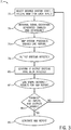
- FIG. 3 is a flow diagram of a process 71 that may be executed by the MPS 10 to excite signals, monitor the behavior of the signals and certain systems, and generate a report, in accordance with an embodiment of the present approach.
- a desired system state and/or operation mode for each input is selected.
- the MPS 10 has been pre-configured to test certain system states in a particular order (e.g., startup, steady state operation, shutdown, etc.). These configurations are generally referred to as testing cycles or scenarios herein.
- a user may utilize a graphical user interface (GUI) to configure the scenarios or testing cycle (e.g., the system states to be excited and the order in which each is excited), as illustrated by FIG. 5 and discussed in detail below.
- GUI graphical user interface
- the excitation system 54 will excite signal(s) that are configured based upon the selected system state (block 74).
- the signal(s) may be DSS sine waves, cosine waves, linear signals, non-linear signals, and the like.
- the MPS 10 processes the excited signals using, for example, the processor 50 as it would process a signal that came from the sensor inputs 42 in the normal course of operation of the connected turbomachinery or other machine system.
- the signals to be output are then sent to the output relays 32 and/or communicated to external systems 26 via the network interface 60, and the corresponding output systems that may be affected in block 78.
- the verification and validation reporting system 64 may monitor the behavior of the signal(s) and confirm if output systems (e.g., systems 10, 18, 26) have been affected as expected for the given scenario (block 80). Further, the verification and validation reporting system 64 may log the results (block 82). To reiterate from the above example, if the "Alert" signals excited for Channel1 and Channel2 did not drive a relay as desired, the verification and validation reporting system 64 will record that failure. In addition to the results, the verification and validation reporting system 64 may log the steps taken by the scenario, such as the channel for which signals were excited, the relay or network utilized, and the output system affected, among other things. Before generating the report, the verification and validation reporting system 64 may determine (decision 84) whether the excitation system is finished.
- output systems e.g., systems 10, 18, 26
- the process 71 determines at decision 84 whether all inputs and outputs for the scenario being run have been verified. If not complete, the process 71 may return to block 72 to select the desired system state and/or fault mode for another input and cycle through the process 71 until completion. Once the process 71 is complete, the verification and validation reporting system 64 will dynamically generate the report (block 86).
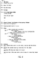
- FIG. 4 is an embodiment of a verification and validation report 100 generated by the verification and validation reporting system 64 included in the MPS 10.
- the verification and validation report 100 depicted may begin with a heading that includes several fields, such as a "performed by" field 102, a date field 104, and a site field 106.
- the "performed by" field 102 will typically include the field engineer's name that performed the test
- the date field 104 may include the date timestamp when the report was generated or the test was completed
- the site field 106 may indicate the site at which the test was performed.
- the verification and validation report 100 may include a "Summary" section 108 that includes subsections, such as the output systems verified 110, the scenario that was run 112, the expected effects of the scenario 118, and verification of the affects 124.
- the output systems verified subsection 110 may include a list of the output systems that were verified and a list of output systems that were not verified, including reason(s) for why the output systems were not verified.
- the title of the output systems verified subsection 110 may be "16/16 Output Systems Verified," which indicates that all 16 output systems that were tested were verified; however any number of output systems may be used.
- Examples of output systems include controllers (e.g., "GE MkVle controller”), external shutdown systems, HMI systems, SCADA systems, DCS systems, components of the MPS 10, and so forth.
- the subsection that indicates which scenario was run 112 may include a number identifying the scenario, a section of the turbomachine or other machine system being tested, the input from the sensor, and the result expected from that input. For example, a sample title may be "Scenario 5: Bearing 1 High Vibration on Direct, requiring a shutdown.”
- information relating to the input 114 and the amount over alarm level 116 may be displayed. For example, the input that is being utilized in Scenario 5 is "channel 6 on input card 2.”
- the excitation system 54 would excite a High Vibration on Direct signal from channel 6 to be processed by the MPS 10.
- the subsection that describes the effects expected from the scenario 118 may provide a hierarchy (e.g., grouping) of information for each of the output systems that are affected.
- the heading for each grouping may include the name of the output system verified and the specific relay or communication network used to connect the MPS 10 and the output system. For example, since the external shutdown system is being verified in this scenario, one heading may be "External shutdown system, output relay 4" 120. Another example may be "GE MkVle controller, industrial protocol, EGD" 122. Under each heading, the relay configuration or communication network mapping may be presented. This provides a field engineer with evidence that the wiring and configuration is accurate if the output system is verified. To that end, the verification subsection 124 may display the results for each of the output systems tested in the scenario.
- This subsection 124 may include a list indicating whether each output system passed or failed for the excited signal and details regarding what happened. For example, one item in the list may read, "pass - external shutdown system trips when bearing 1 experiences high direct vibration" 126. Another example may display "pass - GE MkVle controller receives high vibration status from EGD protocol" 128.
- the verification and validation report 100 may be displayed to the field engineer on a display screen on a device (e.g., the MPS 10 or other devices).
- the device may be a handheld portable computing device such as a laptop, tablet, phone, or a personal digital assistant (PDA), or the device may be a standalone computer located next to the turbomachinery, or other machine system, or in a control room in the facility.
- the verification and validation report 100 may be communicated over the network interface 60 to external systems 26, such as the HMI, SCADA, DCS, controllers, insurance company's systems, or test department systems as proof of desired installation.
- Verification and validation reports 100 may be in any format viewable by a word processing program or a spreadsheet program.
- the verification and validation report 100 may be a MICROSOFT ® Word document, a MICROSOFT ® Excel spreadsheet, and so forth.
- the verification and validation report 100 may be configurable by the field engineer to include certain parameters and fields, to rearrange subsections and headings, and the like. It should be noted that any combination of sections, subsections, headings, scenarios, and information may be displayed via the verification and validation report 100 and the foregoing embodiment was illustrative only and not intended to be limiting. Further, the verification and validation report 100 may be configured to be broadcast to any number of systems. Alternatively, in some embodiments, external systems 26 may communicate with the MPS 10 and request that the verification and validation report 100 be sent to their systems once it is compiled.
- FIG. 5 is a view of a graphic user interface (GUI) 150 that may be displayed to test the configuration of the MPS 10, in accordance with an embodiment of the present approach.
- the GUI 150 may be referred to generally as a system state scenario configurator.
- the system state scenario configurator 150 may contain radio buttons (152 and 154), or any selectable graphic (menus, text boxes, drop down boxes, combo boxes, check boxes, etc.), for a user to choose between testing with virtual hardware or real hardware. In the depicted embodiment, the user has selected the radio button 152 to test with virtual hardware.
- the GUI 150 may contain one or more input card menus 156 and one or more output card menus 158.
- the input card menu(s) 156 may contain a plurality of channels 160, which represent sensor input from a connected machine system, such as a turbomachine system, among others.
- the input card menu(s) 156 may contain a drop down list or selectable graphic 162 associated with each channel 160. From the selectable graphic 162, a user may select which system state (listed above) to excite for a particular channel 160. On the output card menu 158, the user may choose which relay(s) 164 (or other actuators) the channel 160 and system state combination should drive. This configuration results in a system state scenario as referred to above, which may be saved using the save button 166 and/or the scenario may be run using the run button 168. A user can also modify the system state scenario configurator's 150 settings with the settings button 170.
- the settings button 170 may allow the user to change the address of the real hardware, the number of channels 160 on an input card 156, the number of relays 164 on an output card 158, and so forth.
- the MPS 10 may contain default scenarios to excite various system state signals for selected channels 160 and monitor the response of the connected relays 164 and devices.
- a user may customize scenarios to completely test the configuration and wiring of the MPS 10. Further, the scenarios may be reused at later times if saved.
- a field engineer may utilize a software user interface to test the MPS 10 through desired configuration stages. For example, the software may be used to walk through system states to verify that downstream relays are actuating as expected.
- the MPS 10 may be pre-configured to test the various devices' connections with set test cycles or scenarios.
- the connection and scenario testing may be configured by a user.
- the circuitry and/or computer instructions stored on a tangible, non-transitory computer readable medium may bypass the sensor input and excite signals correlative of the sensor input and representing the system states that are to be tested.
Landscapes
- Health & Medical Sciences (AREA)
- Life Sciences & Earth Sciences (AREA)
- Engineering & Computer Science (AREA)
- Physics & Mathematics (AREA)
- Medical Informatics (AREA)
- Animal Behavior & Ethology (AREA)
- Radiology & Medical Imaging (AREA)
- Nuclear Medicine, Radiotherapy & Molecular Imaging (AREA)
- Biomedical Technology (AREA)
- Heart & Thoracic Surgery (AREA)
- Biophysics (AREA)
- Molecular Biology (AREA)
- Surgery (AREA)
- Pathology (AREA)
- General Health & Medical Sciences (AREA)
- Public Health (AREA)
- Veterinary Medicine (AREA)
- General Physics & Mathematics (AREA)
- Automation & Control Theory (AREA)
- Testing And Monitoring For Control Systems (AREA)
- Ultra Sonic Daignosis Equipment (AREA)
Applications Claiming Priority (2)
| Application Number | Priority Date | Filing Date | Title |
|---|---|---|---|
| JP2014014410A JP2015139576A (ja) | 2014-01-29 | 2014-01-29 | 超音波診断装置及びプログラム |
| PCT/US2015/012456 WO2015116469A1 (en) | 2014-01-29 | 2015-01-22 | System and method for verifying the configuration and installation of a monitoring and protection system |
Publications (2)
| Publication Number | Publication Date |
|---|---|
| EP3100125A1 EP3100125A1 (en) | 2016-12-07 |
| EP3100125B1 true EP3100125B1 (en) | 2022-01-05 |
Family
ID=52444673
Family Applications (1)
| Application Number | Title | Priority Date | Filing Date |
|---|---|---|---|
| EP15702360.7A Active EP3100125B1 (en) | 2014-01-29 | 2015-01-22 | System and method for verifying the configuration and installation of a monitoring and protection system |
Country Status (4)
| Country | Link |
|---|---|
| EP (1) | EP3100125B1 (ja) |
| JP (1) | JP2015139576A (ja) |
| DK (1) | DK3100125T3 (ja) |
| WO (2) | WO2015116469A1 (ja) |
Families Citing this family (8)
| Publication number | Priority date | Publication date | Assignee | Title |
|---|---|---|---|---|
| JP6325495B2 (ja) * | 2015-08-28 | 2018-05-16 | ジーイー・メディカル・システムズ・グローバル・テクノロジー・カンパニー・エルエルシー | 超音波診断装置及びそのプログラム |
| JP6664517B2 (ja) | 2016-05-10 | 2020-03-13 | コーニンクレッカ フィリップス エヌ ヴェKoninklijke Philips N.V. | 追跡デバイス |
| KR101931747B1 (ko) | 2016-10-28 | 2019-03-13 | 삼성메디슨 주식회사 | 생체 검사 장치 및 동작 방법 |
| US10613143B2 (en) | 2018-04-03 | 2020-04-07 | Hamilton Sundstrand Corporation | System and method for providing automation of microprocessor analog input stimulation |
| CN109580786B (zh) * | 2018-12-04 | 2020-07-24 | 广州三瑞医疗器械有限公司 | 一种超声探头校准方法 |
| CN110703732B (zh) * | 2019-10-21 | 2021-04-13 | 北京百度网讯科技有限公司 | 相关性检测方法、装置、设备及计算机可读存储介质 |
| WO2023129636A1 (en) * | 2021-12-29 | 2023-07-06 | Creare Llc | Penetrative medical access devices, and related methods and systems |
| CN116269767B (zh) * | 2023-05-22 | 2023-08-08 | 北京迈迪斯医疗技术有限公司 | 一种基于电磁定位的活检系统及导航方法 |
Family Cites Families (10)
| Publication number | Priority date | Publication date | Assignee | Title |
|---|---|---|---|---|
| CA2032384C (en) * | 1989-12-18 | 2000-06-20 | Drexelbrook Controls, Inc. | Remote instrument testing system |
| EP0845959A4 (en) * | 1995-07-16 | 1998-09-30 | Ultra Guide Ltd | HAND-FREE DRAWING A NEEDLE GUIDE |
| AU3985400A (en) * | 1999-04-15 | 2000-11-02 | Ultra-Guide Ltd. | Apparatus and method for detecting the bending of medical invasive tools in medical interventions |
| NO320692B1 (no) * | 2002-12-30 | 2006-01-16 | Stiftelsen Det Norske Veritas | Fremgangsmate og system for testing av datamaskinbaserte styre- og overvakningssystemer i et fartoy via en kommunikasjonskanal |
| JP4828802B2 (ja) | 2004-05-12 | 2011-11-30 | 株式会社東芝 | 穿刺治療のための超音波診断装置 |
| DE102005011246A1 (de) * | 2005-03-11 | 2006-09-14 | Robert Bosch Gmbh | System und Verfahren zum Testen einer Steuergeräteanordnung |
| DE102005041427A1 (de) * | 2005-08-31 | 2007-03-01 | Endress + Hauser Conducta Gesellschaft für Mess- und Regeltechnik mbH + Co. KG | Sensorsimulator |
| NO323949B1 (no) * | 2005-10-31 | 2007-07-23 | Marine Cybernetics As | Framgangsmate og system for testing av et reguleringssystem for et marint petroleumsprosessanlegg |
| US20120143055A1 (en) * | 2010-12-01 | 2012-06-07 | General Electric Company | Method and system for ultrasound imaging |
| JP2012245092A (ja) | 2011-05-26 | 2012-12-13 | Toshiba Corp | 超音波診断装置 |
-
2014
- 2014-01-29 JP JP2014014410A patent/JP2015139576A/ja active Pending
-
2015
- 2015-01-22 DK DK15702360.7T patent/DK3100125T3/da active
- 2015-01-22 EP EP15702360.7A patent/EP3100125B1/en active Active
- 2015-01-22 WO PCT/US2015/012456 patent/WO2015116469A1/en active Application Filing
- 2015-01-27 WO PCT/US2015/013073 patent/WO2015116584A1/en active Application Filing
Also Published As
| Publication number | Publication date |
|---|---|
| WO2015116584A1 (en) | 2015-08-06 |
| DK3100125T3 (da) | 2022-01-31 |
| JP2015139576A (ja) | 2015-08-03 |
| EP3100125A1 (en) | 2016-12-07 |
| WO2015116469A1 (en) | 2015-08-06 |
Similar Documents
| Publication | Publication Date | Title |
|---|---|---|
| EP3100125B1 (en) | System and method for verifying the configuration and installation of a monitoring and protection system | |
| EP2645195B1 (en) | Systems and methods for improved reliability operations | |
| DK2175256T3 (en) | Systems and methods for sensor-level machine monitoring | |
| US9360864B2 (en) | Turbine fault prediction | |
| US9122253B2 (en) | Systems and methods for dynamic risk derivation | |
| US9280617B2 (en) | Systems and methods for improved reliability operations | |
| US9618933B2 (en) | System and method for verifying the configuration and installation of a monitoring and protection system | |
| EP3140700B1 (en) | Systems and methods for monitoring protection devices of an industrial machine | |
| CN106054822B (zh) | 规划和工程设计方法,软件工具和模拟工具 | |
| EP3703075A1 (en) | Method for verifying measurement control system of nuclear power plant, and verification device therefor | |
| US20110264396A1 (en) | Electrical circuit with physical layer diagnostics system | |
| KR20120032450A (ko) | 발전기 작동을 모니터하고 진단하는 방법 및 컴퓨터 시스템 | |
| Ngu et al. | Proactive and predictive maintenance strategies and application for instrumentation & control in oil & gas industry | |
| US7096159B2 (en) | System and method for detecting and excluding outlier sensors in sensor-based monitoring | |
| JP2013228314A (ja) | ディジタル制御盤試験装置およびその試験方法 | |
| CN110506240B (zh) | 工程辅助系统、工程辅助方法、服务器设备、存储介质、客户端设备及客户端程序 | |
| EP3394692B1 (en) | Method and apparatus for analyzing an investigated complex system | |
| JP2019057196A (ja) | 情報収集装置、情報収集方法 | |
| CN111044826A (zh) | 检测方法及检测系统 | |
| CN112462729B (zh) | 用于保护监测系统的影子功能 | |
| JP7059346B1 (ja) | プラントシミュレーション装置およびプラントシミュレーションシステム | |
| KR101824398B1 (ko) | 발전소 계측장비의 현장데이터 실시간 검정 및 보정을 통한 계기판 안정작동 제어방법 및 그 시스템 | |
| JP6037801B2 (ja) | 検査装置、検査システム、及び検査方法 | |
| JP5703927B2 (ja) | 鉄鋼プラントの制御盤設計支援装置 | |
| IT201900016199A1 (it) | Metodo e sistema di test per test a ciclo di I/O per turbomacchine. |
Legal Events
| Date | Code | Title | Description |
|---|---|---|---|
| PUAI | Public reference made under article 153(3) epc to a published international application that has entered the european phase |
Free format text: ORIGINAL CODE: 0009012 |
|
| STAA | Information on the status of an ep patent application or granted ep patent |
Free format text: STATUS: REQUEST FOR EXAMINATION WAS MADE |
|
| 17P | Request for examination filed |
Effective date: 20160829 |
|
| AK | Designated contracting states |
Kind code of ref document: A1 Designated state(s): AL AT BE BG CH CY CZ DE DK EE ES FI FR GB GR HR HU IE IS IT LI LT LU LV MC MK MT NL NO PL PT RO RS SE SI SK SM TR |
|
| AX | Request for extension of the european patent |
Extension state: BA ME |
|
| DAX | Request for extension of the european patent (deleted) | ||
| STAA | Information on the status of an ep patent application or granted ep patent |
Free format text: STATUS: EXAMINATION IS IN PROGRESS |
|
| 17Q | First examination report despatched |
Effective date: 20180301 |
|
| STAA | Information on the status of an ep patent application or granted ep patent |
Free format text: STATUS: EXAMINATION IS IN PROGRESS |
|
| GRAP | Despatch of communication of intention to grant a patent |
Free format text: ORIGINAL CODE: EPIDOSNIGR1 |
|
| STAA | Information on the status of an ep patent application or granted ep patent |
Free format text: STATUS: GRANT OF PATENT IS INTENDED |
|
| INTG | Intention to grant announced |
Effective date: 20210805 |
|
| GRAS | Grant fee paid |
Free format text: ORIGINAL CODE: EPIDOSNIGR3 |
|
| GRAA | (expected) grant |
Free format text: ORIGINAL CODE: 0009210 |
|
| STAA | Information on the status of an ep patent application or granted ep patent |
Free format text: STATUS: THE PATENT HAS BEEN GRANTED |
|
| AK | Designated contracting states |
Kind code of ref document: B1 Designated state(s): AL AT BE BG CH CY CZ DE DK EE ES FI FR GB GR HR HU IE IS IT LI LT LU LV MC MK MT NL NO PL PT RO RS SE SI SK SM TR |
|
| REG | Reference to a national code |
Ref country code: GB Ref legal event code: FG4D |
|
| REG | Reference to a national code |
Ref country code: CH Ref legal event code: EP |
|
| REG | Reference to a national code |
Ref country code: AT Ref legal event code: REF Ref document number: 1461137 Country of ref document: AT Kind code of ref document: T Effective date: 20220115 |
|
| REG | Reference to a national code |
Ref country code: DE Ref legal event code: R096 Ref document number: 602015076217 Country of ref document: DE |
|
| REG | Reference to a national code |
Ref country code: DK Ref legal event code: T3 Effective date: 20220128 |
|
| REG | Reference to a national code |
Ref country code: IE Ref legal event code: FG4D |
|
| REG | Reference to a national code |
Ref country code: SE Ref legal event code: TRGR |
|
| REG | Reference to a national code |
Ref country code: LT Ref legal event code: MG9D |
|
| REG | Reference to a national code |
Ref country code: NL Ref legal event code: MP Effective date: 20220105 |
|
| REG | Reference to a national code |
Ref country code: AT Ref legal event code: MK05 Ref document number: 1461137 Country of ref document: AT Kind code of ref document: T Effective date: 20220105 |
|
| PG25 | Lapsed in a contracting state [announced via postgrant information from national office to epo] |
Ref country code: NL Free format text: LAPSE BECAUSE OF FAILURE TO SUBMIT A TRANSLATION OF THE DESCRIPTION OR TO PAY THE FEE WITHIN THE PRESCRIBED TIME-LIMIT Effective date: 20220105 |
|
| PG25 | Lapsed in a contracting state [announced via postgrant information from national office to epo] |
Ref country code: RS Free format text: LAPSE BECAUSE OF FAILURE TO SUBMIT A TRANSLATION OF THE DESCRIPTION OR TO PAY THE FEE WITHIN THE PRESCRIBED TIME-LIMIT Effective date: 20220105 Ref country code: PT Free format text: LAPSE BECAUSE OF FAILURE TO SUBMIT A TRANSLATION OF THE DESCRIPTION OR TO PAY THE FEE WITHIN THE PRESCRIBED TIME-LIMIT Effective date: 20220505 Ref country code: NO Free format text: LAPSE BECAUSE OF FAILURE TO SUBMIT A TRANSLATION OF THE DESCRIPTION OR TO PAY THE FEE WITHIN THE PRESCRIBED TIME-LIMIT Effective date: 20220405 Ref country code: LT Free format text: LAPSE BECAUSE OF FAILURE TO SUBMIT A TRANSLATION OF THE DESCRIPTION OR TO PAY THE FEE WITHIN THE PRESCRIBED TIME-LIMIT Effective date: 20220105 Ref country code: HR Free format text: LAPSE BECAUSE OF FAILURE TO SUBMIT A TRANSLATION OF THE DESCRIPTION OR TO PAY THE FEE WITHIN THE PRESCRIBED TIME-LIMIT Effective date: 20220105 Ref country code: ES Free format text: LAPSE BECAUSE OF FAILURE TO SUBMIT A TRANSLATION OF THE DESCRIPTION OR TO PAY THE FEE WITHIN THE PRESCRIBED TIME-LIMIT Effective date: 20220105 Ref country code: BG Free format text: LAPSE BECAUSE OF FAILURE TO SUBMIT A TRANSLATION OF THE DESCRIPTION OR TO PAY THE FEE WITHIN THE PRESCRIBED TIME-LIMIT Effective date: 20220405 |
|
| PG25 | Lapsed in a contracting state [announced via postgrant information from national office to epo] |
Ref country code: PL Free format text: LAPSE BECAUSE OF FAILURE TO SUBMIT A TRANSLATION OF THE DESCRIPTION OR TO PAY THE FEE WITHIN THE PRESCRIBED TIME-LIMIT Effective date: 20220105 Ref country code: LV Free format text: LAPSE BECAUSE OF FAILURE TO SUBMIT A TRANSLATION OF THE DESCRIPTION OR TO PAY THE FEE WITHIN THE PRESCRIBED TIME-LIMIT Effective date: 20220105 Ref country code: GR Free format text: LAPSE BECAUSE OF FAILURE TO SUBMIT A TRANSLATION OF THE DESCRIPTION OR TO PAY THE FEE WITHIN THE PRESCRIBED TIME-LIMIT Effective date: 20220406 Ref country code: FI Free format text: LAPSE BECAUSE OF FAILURE TO SUBMIT A TRANSLATION OF THE DESCRIPTION OR TO PAY THE FEE WITHIN THE PRESCRIBED TIME-LIMIT Effective date: 20220105 Ref country code: AT Free format text: LAPSE BECAUSE OF FAILURE TO SUBMIT A TRANSLATION OF THE DESCRIPTION OR TO PAY THE FEE WITHIN THE PRESCRIBED TIME-LIMIT Effective date: 20220105 |
|
| PG25 | Lapsed in a contracting state [announced via postgrant information from national office to epo] |
Ref country code: IS Free format text: LAPSE BECAUSE OF FAILURE TO SUBMIT A TRANSLATION OF THE DESCRIPTION OR TO PAY THE FEE WITHIN THE PRESCRIBED TIME-LIMIT Effective date: 20220505 |
|
| REG | Reference to a national code |
Ref country code: BE Ref legal event code: MM Effective date: 20220131 |
|
| REG | Reference to a national code |
Ref country code: DE Ref legal event code: R097 Ref document number: 602015076217 Country of ref document: DE |
|
| PG25 | Lapsed in a contracting state [announced via postgrant information from national office to epo] |
Ref country code: SM Free format text: LAPSE BECAUSE OF FAILURE TO SUBMIT A TRANSLATION OF THE DESCRIPTION OR TO PAY THE FEE WITHIN THE PRESCRIBED TIME-LIMIT Effective date: 20220105 Ref country code: SK Free format text: LAPSE BECAUSE OF FAILURE TO SUBMIT A TRANSLATION OF THE DESCRIPTION OR TO PAY THE FEE WITHIN THE PRESCRIBED TIME-LIMIT Effective date: 20220105 Ref country code: RO Free format text: LAPSE BECAUSE OF FAILURE TO SUBMIT A TRANSLATION OF THE DESCRIPTION OR TO PAY THE FEE WITHIN THE PRESCRIBED TIME-LIMIT Effective date: 20220105 Ref country code: MC Free format text: LAPSE BECAUSE OF FAILURE TO SUBMIT A TRANSLATION OF THE DESCRIPTION OR TO PAY THE FEE WITHIN THE PRESCRIBED TIME-LIMIT Effective date: 20220105 Ref country code: LU Free format text: LAPSE BECAUSE OF NON-PAYMENT OF DUE FEES Effective date: 20220122 Ref country code: EE Free format text: LAPSE BECAUSE OF FAILURE TO SUBMIT A TRANSLATION OF THE DESCRIPTION OR TO PAY THE FEE WITHIN THE PRESCRIBED TIME-LIMIT Effective date: 20220105 Ref country code: CZ Free format text: LAPSE BECAUSE OF FAILURE TO SUBMIT A TRANSLATION OF THE DESCRIPTION OR TO PAY THE FEE WITHIN THE PRESCRIBED TIME-LIMIT Effective date: 20220105 |
|
| PLBE | No opposition filed within time limit |
Free format text: ORIGINAL CODE: 0009261 |
|
| STAA | Information on the status of an ep patent application or granted ep patent |
Free format text: STATUS: NO OPPOSITION FILED WITHIN TIME LIMIT |
|
| PG25 | Lapsed in a contracting state [announced via postgrant information from national office to epo] |
Ref country code: BE Free format text: LAPSE BECAUSE OF NON-PAYMENT OF DUE FEES Effective date: 20220131 Ref country code: AL Free format text: LAPSE BECAUSE OF FAILURE TO SUBMIT A TRANSLATION OF THE DESCRIPTION OR TO PAY THE FEE WITHIN THE PRESCRIBED TIME-LIMIT Effective date: 20220105 |
|
| 26N | No opposition filed |
Effective date: 20221006 |
|
| PG25 | Lapsed in a contracting state [announced via postgrant information from national office to epo] |
Ref country code: IE Free format text: LAPSE BECAUSE OF NON-PAYMENT OF DUE FEES Effective date: 20220122 Ref country code: FR Free format text: LAPSE BECAUSE OF NON-PAYMENT OF DUE FEES Effective date: 20220305 |
|
| PG25 | Lapsed in a contracting state [announced via postgrant information from national office to epo] |
Ref country code: SI Free format text: LAPSE BECAUSE OF FAILURE TO SUBMIT A TRANSLATION OF THE DESCRIPTION OR TO PAY THE FEE WITHIN THE PRESCRIBED TIME-LIMIT Effective date: 20220105 |
|
| P01 | Opt-out of the competence of the unified patent court (upc) registered |
Effective date: 20230526 |
|
| PG25 | Lapsed in a contracting state [announced via postgrant information from national office to epo] |
Ref country code: IT Free format text: LAPSE BECAUSE OF FAILURE TO SUBMIT A TRANSLATION OF THE DESCRIPTION OR TO PAY THE FEE WITHIN THE PRESCRIBED TIME-LIMIT Effective date: 20220105 |
|
| PGFP | Annual fee paid to national office [announced via postgrant information from national office to epo] |
Ref country code: GB Payment date: 20231219 Year of fee payment: 10 |
|
| PGFP | Annual fee paid to national office [announced via postgrant information from national office to epo] |
Ref country code: SE Payment date: 20231219 Year of fee payment: 10 Ref country code: DK Payment date: 20231219 Year of fee payment: 10 |
|
| PG25 | Lapsed in a contracting state [announced via postgrant information from national office to epo] |
Ref country code: HU Free format text: LAPSE BECAUSE OF FAILURE TO SUBMIT A TRANSLATION OF THE DESCRIPTION OR TO PAY THE FEE WITHIN THE PRESCRIBED TIME-LIMIT; INVALID AB INITIO Effective date: 20150122 |
|
| PG25 | Lapsed in a contracting state [announced via postgrant information from national office to epo] |
Ref country code: MK Free format text: LAPSE BECAUSE OF FAILURE TO SUBMIT A TRANSLATION OF THE DESCRIPTION OR TO PAY THE FEE WITHIN THE PRESCRIBED TIME-LIMIT Effective date: 20220105 Ref country code: CY Free format text: LAPSE BECAUSE OF FAILURE TO SUBMIT A TRANSLATION OF THE DESCRIPTION OR TO PAY THE FEE WITHIN THE PRESCRIBED TIME-LIMIT Effective date: 20220105 |
|
| PGFP | Annual fee paid to national office [announced via postgrant information from national office to epo] |
Ref country code: DE Payment date: 20231219 Year of fee payment: 10 Ref country code: CH Payment date: 20240202 Year of fee payment: 10 |