EP3099974B1 - Led bulb - Google Patents
Led bulb Download PDFInfo
- Publication number
- EP3099974B1 EP3099974B1 EP15701207.1A EP15701207A EP3099974B1 EP 3099974 B1 EP3099974 B1 EP 3099974B1 EP 15701207 A EP15701207 A EP 15701207A EP 3099974 B1 EP3099974 B1 EP 3099974B1
- Authority
- EP
- European Patent Office
- Prior art keywords
- bulb
- leds
- central core
- wall
- light emitting
- Prior art date
- Legal status (The legal status is an assumption and is not a legal conclusion. Google has not performed a legal analysis and makes no representation as to the accuracy of the status listed.)
- Active
Links
Images

Classifications
-
- F—MECHANICAL ENGINEERING; LIGHTING; HEATING; WEAPONS; BLASTING
- F21—LIGHTING
- F21V—FUNCTIONAL FEATURES OR DETAILS OF LIGHTING DEVICES OR SYSTEMS THEREOF; STRUCTURAL COMBINATIONS OF LIGHTING DEVICES WITH OTHER ARTICLES, NOT OTHERWISE PROVIDED FOR
- F21V3/00—Globes; Bowls; Cover glasses
- F21V3/02—Globes; Bowls; Cover glasses characterised by the shape
-
- F—MECHANICAL ENGINEERING; LIGHTING; HEATING; WEAPONS; BLASTING
- F21—LIGHTING
- F21K—NON-ELECTRIC LIGHT SOURCES USING LUMINESCENCE; LIGHT SOURCES USING ELECTROCHEMILUMINESCENCE; LIGHT SOURCES USING CHARGES OF COMBUSTIBLE MATERIAL; LIGHT SOURCES USING SEMICONDUCTOR DEVICES AS LIGHT-GENERATING ELEMENTS; LIGHT SOURCES NOT OTHERWISE PROVIDED FOR
- F21K9/00—Light sources using semiconductor devices as light-generating elements, e.g. using light-emitting diodes [LED] or lasers
- F21K9/20—Light sources comprising attachment means
- F21K9/23—Retrofit light sources for lighting devices with a single fitting for each light source, e.g. for substitution of incandescent lamps with bayonet or threaded fittings
- F21K9/235—Details of bases or caps, i.e. the parts that connect the light source to a fitting; Arrangement of components within bases or caps
-
- F—MECHANICAL ENGINEERING; LIGHTING; HEATING; WEAPONS; BLASTING
- F21—LIGHTING
- F21K—NON-ELECTRIC LIGHT SOURCES USING LUMINESCENCE; LIGHT SOURCES USING ELECTROCHEMILUMINESCENCE; LIGHT SOURCES USING CHARGES OF COMBUSTIBLE MATERIAL; LIGHT SOURCES USING SEMICONDUCTOR DEVICES AS LIGHT-GENERATING ELEMENTS; LIGHT SOURCES NOT OTHERWISE PROVIDED FOR
- F21K9/00—Light sources using semiconductor devices as light-generating elements, e.g. using light-emitting diodes [LED] or lasers
- F21K9/20—Light sources comprising attachment means
- F21K9/23—Retrofit light sources for lighting devices with a single fitting for each light source, e.g. for substitution of incandescent lamps with bayonet or threaded fittings
- F21K9/232—Retrofit light sources for lighting devices with a single fitting for each light source, e.g. for substitution of incandescent lamps with bayonet or threaded fittings specially adapted for generating an essentially omnidirectional light distribution, e.g. with a glass bulb
-
- F—MECHANICAL ENGINEERING; LIGHTING; HEATING; WEAPONS; BLASTING
- F21—LIGHTING
- F21K—NON-ELECTRIC LIGHT SOURCES USING LUMINESCENCE; LIGHT SOURCES USING ELECTROCHEMILUMINESCENCE; LIGHT SOURCES USING CHARGES OF COMBUSTIBLE MATERIAL; LIGHT SOURCES USING SEMICONDUCTOR DEVICES AS LIGHT-GENERATING ELEMENTS; LIGHT SOURCES NOT OTHERWISE PROVIDED FOR
- F21K9/00—Light sources using semiconductor devices as light-generating elements, e.g. using light-emitting diodes [LED] or lasers
- F21K9/20—Light sources comprising attachment means
- F21K9/23—Retrofit light sources for lighting devices with a single fitting for each light source, e.g. for substitution of incandescent lamps with bayonet or threaded fittings
- F21K9/238—Arrangement or mounting of circuit elements integrated in the light source
-
- F—MECHANICAL ENGINEERING; LIGHTING; HEATING; WEAPONS; BLASTING
- F21—LIGHTING
- F21V—FUNCTIONAL FEATURES OR DETAILS OF LIGHTING DEVICES OR SYSTEMS THEREOF; STRUCTURAL COMBINATIONS OF LIGHTING DEVICES WITH OTHER ARTICLES, NOT OTHERWISE PROVIDED FOR
- F21V19/00—Fastening of light sources or lamp holders
- F21V19/001—Fastening of light sources or lamp holders the light sources being semiconductors devices, e.g. LEDs
- F21V19/003—Fastening of light source holders, e.g. of circuit boards or substrates holding light sources
- F21V19/005—Fastening of light source holders, e.g. of circuit boards or substrates holding light sources by permanent fixing means, e.g. gluing, riveting or embedding in a potting compound
-
- F—MECHANICAL ENGINEERING; LIGHTING; HEATING; WEAPONS; BLASTING
- F21—LIGHTING
- F21V—FUNCTIONAL FEATURES OR DETAILS OF LIGHTING DEVICES OR SYSTEMS THEREOF; STRUCTURAL COMBINATIONS OF LIGHTING DEVICES WITH OTHER ARTICLES, NOT OTHERWISE PROVIDED FOR
- F21V23/00—Arrangement of electric circuit elements in or on lighting devices
- F21V23/003—Arrangement of electric circuit elements in or on lighting devices the elements being electronics drivers or controllers for operating the light source, e.g. for a LED array
- F21V23/004—Arrangement of electric circuit elements in or on lighting devices the elements being electronics drivers or controllers for operating the light source, e.g. for a LED array arranged on a substrate, e.g. a printed circuit board
- F21V23/005—Arrangement of electric circuit elements in or on lighting devices the elements being electronics drivers or controllers for operating the light source, e.g. for a LED array arranged on a substrate, e.g. a printed circuit board the substrate is supporting also the light source
-
- F—MECHANICAL ENGINEERING; LIGHTING; HEATING; WEAPONS; BLASTING
- F21—LIGHTING
- F21V—FUNCTIONAL FEATURES OR DETAILS OF LIGHTING DEVICES OR SYSTEMS THEREOF; STRUCTURAL COMBINATIONS OF LIGHTING DEVICES WITH OTHER ARTICLES, NOT OTHERWISE PROVIDED FOR
- F21V29/00—Protecting lighting devices from thermal damage; Cooling or heating arrangements specially adapted for lighting devices or systems
- F21V29/50—Cooling arrangements
- F21V29/502—Cooling arrangements characterised by the adaptation for cooling of specific components
- F21V29/506—Cooling arrangements characterised by the adaptation for cooling of specific components of globes, bowls or cover glasses
-
- F—MECHANICAL ENGINEERING; LIGHTING; HEATING; WEAPONS; BLASTING
- F21—LIGHTING
- F21V—FUNCTIONAL FEATURES OR DETAILS OF LIGHTING DEVICES OR SYSTEMS THEREOF; STRUCTURAL COMBINATIONS OF LIGHTING DEVICES WITH OTHER ARTICLES, NOT OTHERWISE PROVIDED FOR
- F21V29/00—Protecting lighting devices from thermal damage; Cooling or heating arrangements specially adapted for lighting devices or systems
- F21V29/50—Cooling arrangements
- F21V29/70—Cooling arrangements characterised by passive heat-dissipating elements, e.g. heat-sinks
- F21V29/83—Cooling arrangements characterised by passive heat-dissipating elements, e.g. heat-sinks the elements having apertures, ducts or channels, e.g. heat radiation holes
-
- F—MECHANICAL ENGINEERING; LIGHTING; HEATING; WEAPONS; BLASTING
- F21—LIGHTING
- F21V—FUNCTIONAL FEATURES OR DETAILS OF LIGHTING DEVICES OR SYSTEMS THEREOF; STRUCTURAL COMBINATIONS OF LIGHTING DEVICES WITH OTHER ARTICLES, NOT OTHERWISE PROVIDED FOR
- F21V3/00—Globes; Bowls; Cover glasses
- F21V3/04—Globes; Bowls; Cover glasses characterised by materials, surface treatments or coatings
- F21V3/06—Globes; Bowls; Cover glasses characterised by materials, surface treatments or coatings characterised by the material
- F21V3/061—Globes; Bowls; Cover glasses characterised by materials, surface treatments or coatings characterised by the material the material being glass
-
- F—MECHANICAL ENGINEERING; LIGHTING; HEATING; WEAPONS; BLASTING
- F21—LIGHTING
- F21Y—INDEXING SCHEME ASSOCIATED WITH SUBCLASSES F21K, F21L, F21S and F21V, RELATING TO THE FORM OR THE KIND OF THE LIGHT SOURCES OR OF THE COLOUR OF THE LIGHT EMITTED
- F21Y2107/00—Light sources with three-dimensionally disposed light-generating elements
- F21Y2107/30—Light sources with three-dimensionally disposed light-generating elements on the outer surface of cylindrical surfaces, e.g. rod-shaped supports having a circular or a polygonal cross section
-
- F—MECHANICAL ENGINEERING; LIGHTING; HEATING; WEAPONS; BLASTING
- F21—LIGHTING
- F21Y—INDEXING SCHEME ASSOCIATED WITH SUBCLASSES F21K, F21L, F21S and F21V, RELATING TO THE FORM OR THE KIND OF THE LIGHT SOURCES OR OF THE COLOUR OF THE LIGHT EMITTED
- F21Y2115/00—Light-generating elements of semiconductor light sources
- F21Y2115/10—Light-emitting diodes [LED]
Definitions
- the present invention relates generally to a light emitting diode (LED) bulb, and in particular to cooling an LED lamp.
- LED light emitting diode
- LED bulbs also offer the possibility to employ two or more groups or "channels" of LEDs which produce light of different colors, each controllably supplied with predetermined currents to enable the generation and mixing of light to produce general illumination with desired attributes or a desired lighting effect.
- LEDs offer more versatile lighting solutions.
- the standard solution is to provide heat sinking structures for dissipating excess heat.
- LED-based bulbs have reached a level that makes it affordable for consumers. There is however fierce competition among manufacturers of these bulbs, and a huge pressure to reduce the cost price of the bulbs. Despite recent cost reductions, LED bulbs are still relatively expensive. This is mainly the result of the price of the components such as the heat sinks, the LEDs, the driver, the printed circuit board (PCB), as well as the cost associated with mounting the components.
- the components such as the heat sinks, the LEDs, the driver, the printed circuit board (PCB), as well as the cost associated with mounting the components.
- a reduction in cost price is made possible for example by using a light source in the form of a linear array of electrically connected LEDs on a thin and narrow flexible substrate.
- the LEDs can be mounted (soldered) in a continuous linear process.
- a phosphor can be applied (e.g. by dip-coating and drying). Afterwards, the long line of LEDs can be cut to length.
- the length then determines the light output of the bulb.
- the main problem with this proposition is that such a line of LEDs is difficult to cool.
- an LED light bulb comprising:
- the invention provides cooling by using air flow within a hollow core.
- the heating caused by the LEDs promotes air flow by convection, thus providing a continuous supply of cooler air for cooling the LEDs.
- the invention enables a low-cost LED-based light bulb.
- the hollow central core runs from top to bottom and provides an open passageway between the top and bottom, and the base comprises air flow openings which are in communication with the open passageway. In this way, air can flow completely through the central core of the light emitting bulb part.
- the hollow central core has a closed base, and extends from the top of the light emitting bulb part to at least half way into the depth of the light emitting bulb part.
- air flow caused by convection currents still flow within the core to promote cooling.
- the light emitting bulb part can in one example have a shape defined as a surface of revolution generated by revolving a closed shape in three-dimensional space about a top-bottom axis.
- this is a torus-like shape (but the revolved shape is not necessarily a circle).
- the light emitting bulb part can have a shape which is fully rotationally symmetric about the top-bottom axis.
- the chamber can comprise a closed annular volume, with an annular part around the central core, and a radially innermost wall of the annular part defines the central core.
- the shape of the chamber itself defines the core, which extends through the full height or only part of the height of the light emitting bulb part.
- the LEDs can then be provided around the radially innermost wall such that the LEDs are housed within the annular volume. In this way, the LEDs are mounted within the chamber and thus not exposed to the external environment.
- the closed volume of the chamber is completely defined by a glass wall, through which pass electrical connections to the LEDs.
- the closed volume of the chamber is defined by a glass wall having an open base, and a base cover which closes the open base, but leaves an open passage to the central core.
- the base cover can for example comprise a plastic ring.
- the closed volume of the chamber can be defined by an inner cylinder, which defines the innermost wall (i.e. the central core), and an outer wall around the inner cylinder.
- the LEDs can be mounted on the core before the bulb is assembled. This can reduce manufacturing cost.
- the inner cylinder can be plastic, metal or ceramic, and the outer wall can be glass.
- the LEDs can comprise a string of LEDs provided on a flexible substrate.
- This flexible substrate can then be wound around the surface of the inner core.
- the flexible substrate is preferably mounted in contact with a radially innermost wall which defines the central core. This contact provides thermal coupling between the LED substrate and the air flow passageway.
- the inner cylinder can comprise conductive tracks on which the LEDs are mounted.
- the inner cylinder then functions as the circuit board for the LEDs, which can then be mounted over the cylinder as discrete components. This can further reduce the component count.
- an air permeable membrane can be fitted across the open top and/or the open bottom of the hollow central core to filter the air and thus prevent contaminants and impurities from entering the hollow core. This may reduce the effect of dust collecting on the surface of the hollow central core, the dust acts as a thermal insulator and impedes airflow thus reducing the amount of heat dissipation achievable by the hollow core.
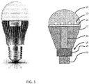
- Figure 1 shows known an LED-based alternative to incandescent light bulbs, particularly A55 and A60 types. The outer appearance is shown on the left, and the internal components are shown schematically on the right. This is known as the MASTER LED bulb available from Koninklijke Philips N.V.
- the bulb includes a plurality of LED light sources 10 provided on a circuit board 11, which is disposed over a heat sink 12. The LEDs emit dimmable light towards a diffusing dome cover 14.
- the bulb has a base which includes an electrical connector 16 and driver circuitry 18 which connects to the LEDs through conduit 20.
- the driver circuitry comprises an AC/DC converter that converts the AC power from the electrical connector to DC power.
- the driver circuitry additionally comprises dimming control circuitry, for example implemented using pulse width modulation (PWM).
- PWM pulse width modulation
- a dimming function is not an essential feature.
- the heat sink 12 is a significant contributor to the cost of the bulb.
- the invention provides an LED light bulb in which the light emitting bulb part comprises a central core running from the top and which provides an open passageway at least to the top.
- the LEDs are mounted in thermal contact around the central core.
- core runs from top to bottom and the base electrical connector comprises air flow openings which are in communication with the open passageway.
- the core only extends partly into the depth of the light emitting bulb part.
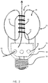
- FIG 2 shows an example of an LED light bulb.
- the same reference numbers are used as in Figure 1 for the same components.
- the LED light bulb again comprises a base 15 which includes an electrical connector 16, which is for connecting the bulb to a corresponding electrical socket.
- a screw fitting is shown, but it may equally be a bayonet fitting, any other twist and lock connection or a push fit connection.
- the electrical connector 16 supplies an LED driver 18, which may be of conventional design.
- the driver electronics is not described in this application, since standard off-the-shelf components can be used.
- the invention relates to the configuration of the LEDs and the light emitting bulb part, and for this reason no detailed discussion is provided concerning the electrical circuits and connections.
- the light emitting bulb part is shown as 22 and it has a bottom facing the base 15 and a top.
- the light emitting bulb part has a hollow central core 24 running from top to bottom and which provides an open passageway between the top and bottom.
- a chamber 25 surrounds the core 24, and the LEDs are mounted around the central core 24.
- the LEDs are mounted on a flexible carrier 26 as a linear strip which is wound around the core within the chamber 25. The leads 27 to the ends of the linear strip pass through the wall of the chamber.
- the base comprises air flow openings 28 which are in communication with the open passageway defined by the central core 24.
- the design provides cooling by using air flow 29 through a passageway running through the light emitting bulb part 22.
- the heating caused by the LED promotes air flow by convection, thus providing a continuous supply of cooler air for cooling the LEDs.
- the light emitting bulb part is preferably rotationally symmetric, so that it has a shape formed by rotating a shape (i.e. the near semicircles to each side of the central core) around the top-bottom axis. This gives a torus-like shape.
- the base 15 and the light emitting bulb part 22 are bonded together.
- the chamber 25 comprises a closed annular volume, and a radially innermost wall defines the central core 24.
- the light emitting bulb part can be made of a single piece of material or two or more pieces.
- the bulb part typically has a glass outer wall, although the outer wall can be plastic or a translucent ceramic such as a densely sintered alumina.
- the LEDs are located close to the central core 24 so that heat transport between the LEDs and the air flow 29 in the core takes place.
- the substrate carrying the linear array of electrically connected LEDs is preferably in contact with the radially innermost wall which defines the central core 24.
- the chamber 25 is closed, and it can thus be filled with a gas that promotes convection inside the bulb, thereby leading to an improved heat transfer from the LEDs to the bulb (as compared to air).
- a gas that promotes convection inside the bulb can be Helium, for example.
- the material of the light emitting bulb part can be translucent (i.e. scattering) to mask the individual LED sources.
- the surface of the inner wall or the outer wall of the central core can be coated with a material promoting heat conduction or heat transfer to the air.
- This coating can be a metal (e.g. aluminium) or a polymer layer with improved thermal conducting properties.
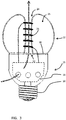
- the light emitting bulb part 22 is open at the lower side.
- the opening can be closed by means of a plastic ring 30 that has a central hole or set of holes 32 to let air through for the convective cooling.
- the closed volume of the chamber is defined by a wall (e.g. glass) having an open base, and a base cover which closes the open base, but leaves an open passage to the central core.
- a wall e.g. glass
- a base cover which closes the open base, but leaves an open passage to the central core.
- This separate component comprises an inner cylinder 34, which defines the innermost wall.
- the glass part forms an outer wall around the inner cylinder.
- the inner cylinder can be plastic, metal or ceramic, and the outer wall can be glass.
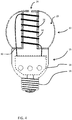
- Figure 5 shows a further example in which the central core 24 has a closed base 40, and the hollow core extends from the top of the light emitting bulb part 22 only partially into the depth of the light emitting bulb part.
- the core provides a cylindrical indentation.
- the LEDs 42 are again within the closed chamber 25 of the light emitting bulb part 22, mounted around the inner wall which defines the core.
- the LEDs can be mounted on a foil-type PCB that is deformed into a cylinder. This cylinder is located close to or in contact with the inner wall which defines the cylindrical shaped indentation in the bulb.
- the light emitting bulb part 22 is not completely annular, but it has an annular part around the core 24.
- the inner wall of the chamber in this annular part again defines the core.
- the arrows 44 show the convective gas flow.
- the core gives rise to an improved conduction of heat generated near the inner parts of the closed chamber towards the outer parts that are accessible by convective air flow.
- the LEDs can comprise a string of LEDs provided on a flexible substrate.
- This flexible substrate can then be wound around the surface of the inner core.
- the flexible substrate is preferably mounted in contact with the radially innermost wall which defines the central core. This contact provides thermal coupling between the LED substrate and the air flow passageway.
- the inner cylinder of the example of Figure 4 can comprise conductive tracks on which the LEDs are mounted.
- the inner cylinder then functions as the circuit board for the LEDs, which can then be mounted over the cylinder as discrete components. This can further reduce the component count.
- the design of Figure 4 means that the bulb is particularly easy and low-cost to make.
- the cylinder can be pre-assembled with the linear LED array or the discrete LEDs into a component that can be inserted and glued into the bulb easily.
- the LEDs can be in good thermal contact with the cylinder by using a thermal adhesive.
- This design also gives more freedom in the choice of materials and dimensions for the bulb and cylinder to result in the most efficient design from a thermal point of view.
- the central core defines a straight passageway running from the top towards the bottom of the light emitting part of the bulb. This is the easiest form to manufacture, since the part of the bulb around the core can be rotationally symmetric around the core.
- the core may take other forms. For example, there may be a central opening at the base. or a central closed end of the core, but the passageway may branch laterally so that the opening in the top is not at the very tip of the bulb. The passageway may be made less visible by displacing the top from the very tip of the bulb/
- the outer envelope of the bulb is preferably designed with scattering properties to mask the appearance of the discrete LEDs inside.
- a clear outer envelope can also be used. If the LEDs are provided on the inside surface of a cylindrical tube, the tube itself can have scattering properties, so that a clear outer envelope can be used.
Landscapes
- Engineering & Computer Science (AREA)
- General Engineering & Computer Science (AREA)
- Microelectronics & Electronic Packaging (AREA)
- Physics & Mathematics (AREA)
- Optics & Photonics (AREA)
- Non-Portable Lighting Devices Or Systems Thereof (AREA)
- Arrangement Of Elements, Cooling, Sealing, Or The Like Of Lighting Devices (AREA)
- Fastening Of Light Sources Or Lamp Holders (AREA)
Priority Applications (1)
| Application Number | Priority Date | Filing Date | Title |
|---|---|---|---|
| PL15701207T PL3099974T3 (pl) | 2014-01-29 | 2015-01-26 | Żarówka led |
Applications Claiming Priority (2)
| Application Number | Priority Date | Filing Date | Title |
|---|---|---|---|
| EP14153059 | 2014-01-29 | ||
| PCT/EP2015/051424 WO2015113913A1 (en) | 2014-01-29 | 2015-01-26 | Led bulb |
Publications (2)
| Publication Number | Publication Date |
|---|---|
| EP3099974A1 EP3099974A1 (en) | 2016-12-07 |
| EP3099974B1 true EP3099974B1 (en) | 2017-09-13 |
Family
ID=50002610
Family Applications (1)
| Application Number | Title | Priority Date | Filing Date |
|---|---|---|---|
| EP15701207.1A Active EP3099974B1 (en) | 2014-01-29 | 2015-01-26 | Led bulb |
Country Status (7)
| Country | Link |
|---|---|
| US (1) | US9995437B2 (enExample) |
| EP (1) | EP3099974B1 (enExample) |
| JP (1) | JP6603228B2 (enExample) |
| CN (1) | CN105940263B (enExample) |
| PL (1) | PL3099974T3 (enExample) |
| RU (1) | RU2671617C2 (enExample) |
| WO (1) | WO2015113913A1 (enExample) |
Families Citing this family (4)
| Publication number | Priority date | Publication date | Assignee | Title |
|---|---|---|---|---|
| EP3193073A1 (en) * | 2016-01-14 | 2017-07-19 | Philips Lighting Holding B.V. | A lighting device |
| KR102461385B1 (ko) * | 2017-10-31 | 2022-11-01 | 쑤저우 레킨 세미컨덕터 컴퍼니 리미티드 | 다색 발광 조명 장치 |
| CN111156432B (zh) * | 2020-02-11 | 2025-10-17 | 葛铁汉 | 一种全方位出光灯罩及具有该灯罩的灯泡 |
| CN114543003A (zh) * | 2022-03-01 | 2022-05-27 | 厦门阳光恩耐照明有限公司 | 加快散热的led灯 |
Family Cites Families (25)
| Publication number | Priority date | Publication date | Assignee | Title |
|---|---|---|---|---|
| JP2004296245A (ja) * | 2003-03-26 | 2004-10-21 | Matsushita Electric Works Ltd | Ledランプ |
| DE102007040444B8 (de) | 2007-08-28 | 2013-10-17 | Osram Gmbh | LED-Lampe |
| CN101457913B (zh) * | 2007-12-12 | 2011-09-28 | 富准精密工业(深圳)有限公司 | 发光二极管灯具 |
| EP2245367A4 (en) * | 2008-01-15 | 2015-08-12 | Philip Premysler | OMNIDIRECTIONAL LED BULB |
| CN101251246A (zh) * | 2008-03-24 | 2008-08-27 | 东莞勤上光电股份有限公司 | Led灯具及其散热方法 |
| US7950836B2 (en) * | 2008-05-09 | 2011-05-31 | Osram Sylvania Inc. | EMI controlled integral HID reflector lamp |
| KR101032414B1 (ko) | 2008-06-25 | 2011-05-03 | (주) 아모엘이디 | 엘이디 패키지 및 그 제조방법 |
| US20120049732A1 (en) * | 2010-08-26 | 2012-03-01 | Chuang Sheng-Yi | Led light bulb |
| US20130016508A1 (en) * | 2011-07-13 | 2013-01-17 | Curt Progl | Variable thickness globe |
| JP6161872B2 (ja) | 2011-07-14 | 2017-07-12 | 三菱電機照明株式会社 | 発光ダイオードランプ及び照明器具及び発光ダイオードランプの製造方法 |
| US8931924B2 (en) * | 2011-10-11 | 2015-01-13 | Uniled Lighting Taiwan Inc. | Heat sink for LED lamp |
| CN202303274U (zh) | 2011-10-11 | 2012-07-04 | 厦门市东林电子有限公司 | 一种led灯散热结构 |
| US9194541B2 (en) * | 2011-11-10 | 2015-11-24 | Epistar Corporation | Illumination apparatus |
| US8944639B2 (en) | 2011-12-14 | 2015-02-03 | Leroy E. Anderson | LED room light with multiple LEDs and radiator fins |
| JP2013127878A (ja) * | 2011-12-16 | 2013-06-27 | Samsung Electronics Co Ltd | 電球形照明装置 |
| CN202432304U (zh) * | 2011-12-30 | 2012-09-12 | 上海顿格电子贸易有限公司 | 空气自然内外对流散热的大角度led球泡灯 |
| WO2013109161A1 (ru) | 2012-01-20 | 2013-07-25 | Общество с ограниченной ответственностью "ДиС ПЛЮС" | Светодиодная лампа общего назначения |
| JP3178903U (ja) * | 2012-07-25 | 2012-10-04 | 臺灣利他股▲ふん▼有限公司 | ランプの芯構造 |
| CN202719428U (zh) * | 2012-08-06 | 2013-02-06 | 深圳市中电照明股份有限公司 | 一种对流散热式led灯泡 |
| CN202946967U (zh) * | 2012-11-19 | 2013-05-22 | 史杰 | 一种带尾巴有散热通道的led灯泡 |
| US9644799B2 (en) * | 2013-03-13 | 2017-05-09 | Smartbotics Inc. | LED light bulb construction and manufacture |
| US9657922B2 (en) * | 2013-03-15 | 2017-05-23 | Cree, Inc. | Electrically insulative coatings for LED lamp and elements |
| CN103244933A (zh) * | 2013-05-28 | 2013-08-14 | 浙江名芯半导体科技有限公司 | 带有内部对流散热结构的led灯泡及led光源设备 |
| TWM472161U (zh) * | 2013-09-18 | 2014-02-11 | Huang Tai Yin | 發光二極體燈具 |
| US9759388B2 (en) * | 2013-11-11 | 2017-09-12 | Ningbo Qtop Import & Export Co., Ltd. | LED light bulb assembly |
-
2015
- 2015-01-26 PL PL15701207T patent/PL3099974T3/pl unknown
- 2015-01-26 WO PCT/EP2015/051424 patent/WO2015113913A1/en not_active Ceased
- 2015-01-26 RU RU2016134901A patent/RU2671617C2/ru active
- 2015-01-26 JP JP2016548665A patent/JP6603228B2/ja active Active
- 2015-01-26 EP EP15701207.1A patent/EP3099974B1/en active Active
- 2015-01-26 US US15/114,200 patent/US9995437B2/en active Active
- 2015-01-26 CN CN201580006383.6A patent/CN105940263B/zh active Active
Non-Patent Citations (1)
| Title |
|---|
| None * |
Also Published As
| Publication number | Publication date |
|---|---|
| US20170002985A1 (en) | 2017-01-05 |
| EP3099974A1 (en) | 2016-12-07 |
| CN105940263A (zh) | 2016-09-14 |
| US9995437B2 (en) | 2018-06-12 |
| PL3099974T3 (pl) | 2018-06-29 |
| RU2016134901A3 (enExample) | 2018-09-03 |
| CN105940263B (zh) | 2020-05-29 |
| JP6603228B2 (ja) | 2019-11-06 |
| JP2017504943A (ja) | 2017-02-09 |
| RU2671617C2 (ru) | 2018-11-02 |
| RU2016134901A (ru) | 2018-03-05 |
| WO2015113913A1 (en) | 2015-08-06 |
Similar Documents
| Publication | Publication Date | Title |
|---|---|---|
| JP5348410B2 (ja) | 口金付ランプおよび照明器具 | |
| JP5795632B2 (ja) | Led電球 | |
| US9016924B2 (en) | Lamp device | |
| US20170012177A1 (en) | Led based lighting system | |
| US20120217870A1 (en) | LED Light Assembly | |
| CN103649636A (zh) | 用于基于led的灯泡或灯具装置的传热组件 | |
| US8947002B2 (en) | LED bulb with color-shift dimming | |
| MX2008013870A (es) | Bulbo de led de plastico. | |
| US20160341370A1 (en) | Led bulb | |
| CA2889834C (en) | Light emitting diode spotlight | |
| EP3099974B1 (en) | Led bulb | |
| JP5472793B2 (ja) | 照明装置および照明器具 | |
| JP5374003B1 (ja) | 照明用光源及び照明装置 | |
| US11592166B2 (en) | Light emitting device having improved illumination and manufacturing flexibility | |
| CN103775904A (zh) | 一种简单实用陶瓷漏光结构的led射灯 |
Legal Events
| Date | Code | Title | Description |
|---|---|---|---|
| PUAI | Public reference made under article 153(3) epc to a published international application that has entered the european phase |
Free format text: ORIGINAL CODE: 0009012 |
|
| 17P | Request for examination filed |
Effective date: 20160829 |
|
| AK | Designated contracting states |
Kind code of ref document: A1 Designated state(s): AL AT BE BG CH CY CZ DE DK EE ES FI FR GB GR HR HU IE IS IT LI LT LU LV MC MK MT NL NO PL PT RO RS SE SI SK SM TR |
|
| AX | Request for extension of the european patent |
Extension state: BA ME |
|
| GRAJ | Information related to disapproval of communication of intention to grant by the applicant or resumption of examination proceedings by the epo deleted |
Free format text: ORIGINAL CODE: EPIDOSDIGR1 |
|
| GRAP | Despatch of communication of intention to grant a patent |
Free format text: ORIGINAL CODE: EPIDOSNIGR1 |
|
| DAX | Request for extension of the european patent (deleted) | ||
| INTG | Intention to grant announced |
Effective date: 20170331 |
|
| GRAS | Grant fee paid |
Free format text: ORIGINAL CODE: EPIDOSNIGR3 |
|
| GRAA | (expected) grant |
Free format text: ORIGINAL CODE: 0009210 |
|
| RIN1 | Information on inventor provided before grant (corrected) |
Inventor name: VAN NEER, ALEXANDER JACOBUS MARIETTE Inventor name: DE ZWART, SIEBE TJERK Inventor name: DEKKER, TIM Inventor name: GOMMANS, HENDRIKUS HUBERTUS PETRUS Inventor name: KRIJN, MARCELLINUS PETRUS CAROLUS MICHAEL Inventor name: VAN GHELUWE, JOCHEN RENAAT |
|
| AK | Designated contracting states |
Kind code of ref document: B1 Designated state(s): AL AT BE BG CH CY CZ DE DK EE ES FI FR GB GR HR HU IE IS IT LI LT LU LV MC MK MT NL NO PL PT RO RS SE SI SK SM TR |
|
| REG | Reference to a national code |
Ref country code: GB Ref legal event code: FG4D |
|
| REG | Reference to a national code |
Ref country code: CH Ref legal event code: EP |
|
| REG | Reference to a national code |
Ref country code: IE Ref legal event code: FG4D |
|
| REG | Reference to a national code |
Ref country code: AT Ref legal event code: REF Ref document number: 928530 Country of ref document: AT Kind code of ref document: T Effective date: 20171015 |
|
| REG | Reference to a national code |
Ref country code: DE Ref legal event code: R096 Ref document number: 602015004771 Country of ref document: DE |
|
| REG | Reference to a national code |
Ref country code: NL Ref legal event code: MP Effective date: 20170913 |
|
| REG | Reference to a national code |
Ref country code: LT Ref legal event code: MG4D |
|
| PG25 | Lapsed in a contracting state [announced via postgrant information from national office to epo] |
Ref country code: LT Free format text: LAPSE BECAUSE OF FAILURE TO SUBMIT A TRANSLATION OF THE DESCRIPTION OR TO PAY THE FEE WITHIN THE PRESCRIBED TIME-LIMIT Effective date: 20170913 Ref country code: SE Free format text: LAPSE BECAUSE OF FAILURE TO SUBMIT A TRANSLATION OF THE DESCRIPTION OR TO PAY THE FEE WITHIN THE PRESCRIBED TIME-LIMIT Effective date: 20170913 Ref country code: FI Free format text: LAPSE BECAUSE OF FAILURE TO SUBMIT A TRANSLATION OF THE DESCRIPTION OR TO PAY THE FEE WITHIN THE PRESCRIBED TIME-LIMIT Effective date: 20170913 Ref country code: NO Free format text: LAPSE BECAUSE OF FAILURE TO SUBMIT A TRANSLATION OF THE DESCRIPTION OR TO PAY THE FEE WITHIN THE PRESCRIBED TIME-LIMIT Effective date: 20171213 Ref country code: HR Free format text: LAPSE BECAUSE OF FAILURE TO SUBMIT A TRANSLATION OF THE DESCRIPTION OR TO PAY THE FEE WITHIN THE PRESCRIBED TIME-LIMIT Effective date: 20170913 |
|
| REG | Reference to a national code |
Ref country code: AT Ref legal event code: MK05 Ref document number: 928530 Country of ref document: AT Kind code of ref document: T Effective date: 20170913 |
|
| PG25 | Lapsed in a contracting state [announced via postgrant information from national office to epo] |
Ref country code: RS Free format text: LAPSE BECAUSE OF FAILURE TO SUBMIT A TRANSLATION OF THE DESCRIPTION OR TO PAY THE FEE WITHIN THE PRESCRIBED TIME-LIMIT Effective date: 20170913 Ref country code: ES Free format text: LAPSE BECAUSE OF FAILURE TO SUBMIT A TRANSLATION OF THE DESCRIPTION OR TO PAY THE FEE WITHIN THE PRESCRIBED TIME-LIMIT Effective date: 20170913 Ref country code: BG Free format text: LAPSE BECAUSE OF FAILURE TO SUBMIT A TRANSLATION OF THE DESCRIPTION OR TO PAY THE FEE WITHIN THE PRESCRIBED TIME-LIMIT Effective date: 20171213 Ref country code: LV Free format text: LAPSE BECAUSE OF FAILURE TO SUBMIT A TRANSLATION OF THE DESCRIPTION OR TO PAY THE FEE WITHIN THE PRESCRIBED TIME-LIMIT Effective date: 20170913 Ref country code: GR Free format text: LAPSE BECAUSE OF FAILURE TO SUBMIT A TRANSLATION OF THE DESCRIPTION OR TO PAY THE FEE WITHIN THE PRESCRIBED TIME-LIMIT Effective date: 20171214 |
|
| PG25 | Lapsed in a contracting state [announced via postgrant information from national office to epo] |
Ref country code: NL Free format text: LAPSE BECAUSE OF FAILURE TO SUBMIT A TRANSLATION OF THE DESCRIPTION OR TO PAY THE FEE WITHIN THE PRESCRIBED TIME-LIMIT Effective date: 20170913 |
|
| PG25 | Lapsed in a contracting state [announced via postgrant information from national office to epo] |
Ref country code: CZ Free format text: LAPSE BECAUSE OF FAILURE TO SUBMIT A TRANSLATION OF THE DESCRIPTION OR TO PAY THE FEE WITHIN THE PRESCRIBED TIME-LIMIT Effective date: 20170913 |
|
| PG25 | Lapsed in a contracting state [announced via postgrant information from national office to epo] |
Ref country code: EE Free format text: LAPSE BECAUSE OF FAILURE TO SUBMIT A TRANSLATION OF THE DESCRIPTION OR TO PAY THE FEE WITHIN THE PRESCRIBED TIME-LIMIT Effective date: 20170913 Ref country code: IT Free format text: LAPSE BECAUSE OF FAILURE TO SUBMIT A TRANSLATION OF THE DESCRIPTION OR TO PAY THE FEE WITHIN THE PRESCRIBED TIME-LIMIT Effective date: 20170913 Ref country code: IS Free format text: LAPSE BECAUSE OF FAILURE TO SUBMIT A TRANSLATION OF THE DESCRIPTION OR TO PAY THE FEE WITHIN THE PRESCRIBED TIME-LIMIT Effective date: 20180113 Ref country code: AT Free format text: LAPSE BECAUSE OF FAILURE TO SUBMIT A TRANSLATION OF THE DESCRIPTION OR TO PAY THE FEE WITHIN THE PRESCRIBED TIME-LIMIT Effective date: 20170913 Ref country code: SM Free format text: LAPSE BECAUSE OF FAILURE TO SUBMIT A TRANSLATION OF THE DESCRIPTION OR TO PAY THE FEE WITHIN THE PRESCRIBED TIME-LIMIT Effective date: 20170913 Ref country code: SK Free format text: LAPSE BECAUSE OF FAILURE TO SUBMIT A TRANSLATION OF THE DESCRIPTION OR TO PAY THE FEE WITHIN THE PRESCRIBED TIME-LIMIT Effective date: 20170913 |
|
| REG | Reference to a national code |
Ref country code: DE Ref legal event code: R097 Ref document number: 602015004771 Country of ref document: DE |
|
| PLBE | No opposition filed within time limit |
Free format text: ORIGINAL CODE: 0009261 |
|
| STAA | Information on the status of an ep patent application or granted ep patent |
Free format text: STATUS: NO OPPOSITION FILED WITHIN TIME LIMIT |
|
| PG25 | Lapsed in a contracting state [announced via postgrant information from national office to epo] |
Ref country code: DK Free format text: LAPSE BECAUSE OF FAILURE TO SUBMIT A TRANSLATION OF THE DESCRIPTION OR TO PAY THE FEE WITHIN THE PRESCRIBED TIME-LIMIT Effective date: 20170913 |
|
| 26N | No opposition filed |
Effective date: 20180614 |
|
| REG | Reference to a national code |
Ref country code: CH Ref legal event code: PL |
|
| PG25 | Lapsed in a contracting state [announced via postgrant information from national office to epo] |
Ref country code: LU Free format text: LAPSE BECAUSE OF NON-PAYMENT OF DUE FEES Effective date: 20180126 Ref country code: FR Free format text: LAPSE BECAUSE OF NON-PAYMENT OF DUE FEES Effective date: 20180131 |
|
| REG | Reference to a national code |
Ref country code: IE Ref legal event code: MM4A |
|
| REG | Reference to a national code |
Ref country code: FR Ref legal event code: ST Effective date: 20180928 |
|
| REG | Reference to a national code |
Ref country code: BE Ref legal event code: MM Effective date: 20180131 |
|
| PG25 | Lapsed in a contracting state [announced via postgrant information from national office to epo] |
Ref country code: BE Free format text: LAPSE BECAUSE OF NON-PAYMENT OF DUE FEES Effective date: 20180131 Ref country code: SI Free format text: LAPSE BECAUSE OF FAILURE TO SUBMIT A TRANSLATION OF THE DESCRIPTION OR TO PAY THE FEE WITHIN THE PRESCRIBED TIME-LIMIT Effective date: 20170913 Ref country code: LI Free format text: LAPSE BECAUSE OF NON-PAYMENT OF DUE FEES Effective date: 20180131 Ref country code: CH Free format text: LAPSE BECAUSE OF NON-PAYMENT OF DUE FEES Effective date: 20180131 |
|
| PG25 | Lapsed in a contracting state [announced via postgrant information from national office to epo] |
Ref country code: IE Free format text: LAPSE BECAUSE OF NON-PAYMENT OF DUE FEES Effective date: 20180126 |
|
| PG25 | Lapsed in a contracting state [announced via postgrant information from national office to epo] |
Ref country code: MC Free format text: LAPSE BECAUSE OF FAILURE TO SUBMIT A TRANSLATION OF THE DESCRIPTION OR TO PAY THE FEE WITHIN THE PRESCRIBED TIME-LIMIT Effective date: 20170913 |
|
| PG25 | Lapsed in a contracting state [announced via postgrant information from national office to epo] |
Ref country code: MT Free format text: LAPSE BECAUSE OF NON-PAYMENT OF DUE FEES Effective date: 20180126 |
|
| PG25 | Lapsed in a contracting state [announced via postgrant information from national office to epo] |
Ref country code: TR Free format text: LAPSE BECAUSE OF FAILURE TO SUBMIT A TRANSLATION OF THE DESCRIPTION OR TO PAY THE FEE WITHIN THE PRESCRIBED TIME-LIMIT Effective date: 20170913 |
|
| PG25 | Lapsed in a contracting state [announced via postgrant information from national office to epo] |
Ref country code: PT Free format text: LAPSE BECAUSE OF FAILURE TO SUBMIT A TRANSLATION OF THE DESCRIPTION OR TO PAY THE FEE WITHIN THE PRESCRIBED TIME-LIMIT Effective date: 20170913 |
|
| PG25 | Lapsed in a contracting state [announced via postgrant information from national office to epo] |
Ref country code: CY Free format text: LAPSE BECAUSE OF FAILURE TO SUBMIT A TRANSLATION OF THE DESCRIPTION OR TO PAY THE FEE WITHIN THE PRESCRIBED TIME-LIMIT Effective date: 20170913 Ref country code: RO Free format text: LAPSE BECAUSE OF FAILURE TO SUBMIT A TRANSLATION OF THE DESCRIPTION OR TO PAY THE FEE WITHIN THE PRESCRIBED TIME-LIMIT Effective date: 20170913 Ref country code: HU Free format text: LAPSE BECAUSE OF FAILURE TO SUBMIT A TRANSLATION OF THE DESCRIPTION OR TO PAY THE FEE WITHIN THE PRESCRIBED TIME-LIMIT; INVALID AB INITIO Effective date: 20150126 Ref country code: MK Free format text: LAPSE BECAUSE OF NON-PAYMENT OF DUE FEES Effective date: 20170913 |
|
| PG25 | Lapsed in a contracting state [announced via postgrant information from national office to epo] |
Ref country code: AL Free format text: LAPSE BECAUSE OF FAILURE TO SUBMIT A TRANSLATION OF THE DESCRIPTION OR TO PAY THE FEE WITHIN THE PRESCRIBED TIME-LIMIT Effective date: 20170913 |
|
| REG | Reference to a national code |
Ref country code: DE Ref legal event code: R081 Ref document number: 602015004771 Country of ref document: DE Owner name: SIGNIFY HOLDING B.V., NL Free format text: FORMER OWNER: PHILIPS LIGHTING HOLDING B.V., EINDHOVEN, NL |
|
| P01 | Opt-out of the competence of the unified patent court (upc) registered |
Effective date: 20230421 |
|
| PGFP | Annual fee paid to national office [announced via postgrant information from national office to epo] |
Ref country code: GB Payment date: 20260126 Year of fee payment: 12 |
|
| PGFP | Annual fee paid to national office [announced via postgrant information from national office to epo] |
Ref country code: DE Payment date: 20260320 Year of fee payment: 12 |
|
| PGFP | Annual fee paid to national office [announced via postgrant information from national office to epo] |
Ref country code: PL Payment date: 20260113 Year of fee payment: 12 |