EP3098689A1 - Dispositif d'affichage d'images et procédé d'affichage d'images - Google Patents
Dispositif d'affichage d'images et procédé d'affichage d'images Download PDFInfo
- Publication number
- EP3098689A1 EP3098689A1 EP14879372.2A EP14879372A EP3098689A1 EP 3098689 A1 EP3098689 A1 EP 3098689A1 EP 14879372 A EP14879372 A EP 14879372A EP 3098689 A1 EP3098689 A1 EP 3098689A1
- Authority
- EP
- European Patent Office
- Prior art keywords
- image
- real world
- region
- display
- unit
- Prior art date
- Legal status (The legal status is an assumption and is not a legal conclusion. Google has not performed a legal analysis and makes no representation as to the accuracy of the status listed.)
- Granted
Links
- 238000000034 method Methods 0.000 title claims abstract description 52
- 238000001514 detection method Methods 0.000 claims description 37
- 238000009877 rendering Methods 0.000 claims description 28
- 230000008569 process Effects 0.000 claims description 18
- 238000012821 model calculation Methods 0.000 claims description 13
- 239000000203 mixture Substances 0.000 claims description 9
- 230000006854 communication Effects 0.000 description 22
- 238000004891 communication Methods 0.000 description 21
- 210000003128 head Anatomy 0.000 description 18
- 238000005516 engineering process Methods 0.000 description 17
- 238000010586 diagram Methods 0.000 description 16
- 230000003287 optical effect Effects 0.000 description 12
- 238000012545 processing Methods 0.000 description 11
- 238000007654 immersion Methods 0.000 description 8
- 230000000694 effects Effects 0.000 description 6
- 238000005401 electroluminescence Methods 0.000 description 6
- 230000006870 function Effects 0.000 description 6
- MWUXSHHQAYIFBG-UHFFFAOYSA-N nitrogen oxide Inorganic materials O=[N] MWUXSHHQAYIFBG-UHFFFAOYSA-N 0.000 description 5
- 230000004886 head movement Effects 0.000 description 4
- 230000003467 diminishing effect Effects 0.000 description 3
- 230000007613 environmental effect Effects 0.000 description 3
- 230000003993 interaction Effects 0.000 description 3
- 239000004973 liquid crystal related substance Substances 0.000 description 3
- 230000002207 retinal effect Effects 0.000 description 3
- CURLTUGMZLYLDI-UHFFFAOYSA-N Carbon dioxide Chemical compound O=C=O CURLTUGMZLYLDI-UHFFFAOYSA-N 0.000 description 2
- 230000001133 acceleration Effects 0.000 description 2
- 238000012937 correction Methods 0.000 description 2
- 230000007246 mechanism Effects 0.000 description 2
- 230000003183 myoelectrical effect Effects 0.000 description 2
- 210000001747 pupil Anatomy 0.000 description 2
- 238000001454 recorded image Methods 0.000 description 2
- 230000005236 sound signal Effects 0.000 description 2
- 239000012855 volatile organic compound Substances 0.000 description 2
- SNICXCGAKADSCV-JTQLQIEISA-N (-)-Nicotine Chemical compound CN1CCC[C@H]1C1=CC=CN=C1 SNICXCGAKADSCV-JTQLQIEISA-N 0.000 description 1
- WBMKMLWMIQUJDP-STHHAXOLSA-N (4R,4aS,7aR,12bS)-4a,9-dihydroxy-3-prop-2-ynyl-2,4,5,6,7a,13-hexahydro-1H-4,12-methanobenzofuro[3,2-e]isoquinolin-7-one hydrochloride Chemical compound Cl.Oc1ccc2C[C@H]3N(CC#C)CC[C@@]45[C@@H](Oc1c24)C(=O)CC[C@@]35O WBMKMLWMIQUJDP-STHHAXOLSA-N 0.000 description 1
- UGFAIRIUMAVXCW-UHFFFAOYSA-N Carbon monoxide Chemical compound [O+]#[C-] UGFAIRIUMAVXCW-UHFFFAOYSA-N 0.000 description 1
- 230000036626 alertness Effects 0.000 description 1
- 230000003321 amplification Effects 0.000 description 1
- 239000010425 asbestos Substances 0.000 description 1
- QVGXLLKOCUKJST-UHFFFAOYSA-N atomic oxygen Chemical compound [O] QVGXLLKOCUKJST-UHFFFAOYSA-N 0.000 description 1
- 230000003542 behavioural effect Effects 0.000 description 1
- 230000005540 biological transmission Effects 0.000 description 1
- 230000036760 body temperature Effects 0.000 description 1
- 210000004556 brain Anatomy 0.000 description 1
- 229910002092 carbon dioxide Inorganic materials 0.000 description 1
- 239000001569 carbon dioxide Substances 0.000 description 1
- 229910002091 carbon monoxide Inorganic materials 0.000 description 1
- 230000001413 cellular effect Effects 0.000 description 1
- 230000008859 change Effects 0.000 description 1
- 239000000428 dust Substances 0.000 description 1
- 230000008451 emotion Effects 0.000 description 1
- 210000000744 eyelid Anatomy 0.000 description 1
- 239000010419 fine particle Substances 0.000 description 1
- 238000007667 floating Methods 0.000 description 1
- 239000007789 gas Substances 0.000 description 1
- 239000000383 hazardous chemical Substances 0.000 description 1
- 229930195733 hydrocarbon Natural products 0.000 description 1
- 150000002430 hydrocarbons Chemical class 0.000 description 1
- 230000001939 inductive effect Effects 0.000 description 1
- 150000002500 ions Chemical class 0.000 description 1
- 230000004807 localization Effects 0.000 description 1
- 230000007774 longterm Effects 0.000 description 1
- 238000004519 manufacturing process Methods 0.000 description 1
- 238000013507 mapping Methods 0.000 description 1
- 238000005259 measurement Methods 0.000 description 1
- 238000012986 modification Methods 0.000 description 1
- 230000004048 modification Effects 0.000 description 1
- 229960002715 nicotine Drugs 0.000 description 1
- SNICXCGAKADSCV-UHFFFAOYSA-N nicotine Natural products CN1CCCC1C1=CC=CN=C1 SNICXCGAKADSCV-UHFFFAOYSA-N 0.000 description 1
- QJGQUHMNIGDVPM-UHFFFAOYSA-N nitrogen group Chemical group [N] QJGQUHMNIGDVPM-UHFFFAOYSA-N 0.000 description 1
- 238000003199 nucleic acid amplification method Methods 0.000 description 1
- 239000001301 oxygen Substances 0.000 description 1
- 229910052760 oxygen Inorganic materials 0.000 description 1
- 239000013618 particulate matter Substances 0.000 description 1
- 230000008447 perception Effects 0.000 description 1
- 238000006552 photochemical reaction Methods 0.000 description 1
- -1 pollen Substances 0.000 description 1
- 230000005855 radiation Effects 0.000 description 1
- 229910052895 riebeckite Inorganic materials 0.000 description 1
- 239000000779 smoke Substances 0.000 description 1
- 239000000126 substance Substances 0.000 description 1
- 238000006467 substitution reaction Methods 0.000 description 1
- 210000004243 sweat Anatomy 0.000 description 1
- 230000000007 visual effect Effects 0.000 description 1
Images


Classifications
-
- G—PHYSICS
- G06—COMPUTING; CALCULATING OR COUNTING
- G06F—ELECTRIC DIGITAL DATA PROCESSING
- G06F3/00—Input arrangements for transferring data to be processed into a form capable of being handled by the computer; Output arrangements for transferring data from processing unit to output unit, e.g. interface arrangements
- G06F3/01—Input arrangements or combined input and output arrangements for interaction between user and computer
- G06F3/011—Arrangements for interaction with the human body, e.g. for user immersion in virtual reality
- G06F3/013—Eye tracking input arrangements
-
- G—PHYSICS
- G06—COMPUTING; CALCULATING OR COUNTING
- G06F—ELECTRIC DIGITAL DATA PROCESSING
- G06F3/00—Input arrangements for transferring data to be processed into a form capable of being handled by the computer; Output arrangements for transferring data from processing unit to output unit, e.g. interface arrangements
- G06F3/01—Input arrangements or combined input and output arrangements for interaction between user and computer
- G06F3/017—Gesture based interaction, e.g. based on a set of recognized hand gestures
-
- G—PHYSICS
- G06—COMPUTING; CALCULATING OR COUNTING
- G06F—ELECTRIC DIGITAL DATA PROCESSING
- G06F3/00—Input arrangements for transferring data to be processed into a form capable of being handled by the computer; Output arrangements for transferring data from processing unit to output unit, e.g. interface arrangements
- G06F3/01—Input arrangements or combined input and output arrangements for interaction between user and computer
- G06F3/03—Arrangements for converting the position or the displacement of a member into a coded form
- G06F3/041—Digitisers, e.g. for touch screens or touch pads, characterised by the transducing means
-
- G—PHYSICS
- G06—COMPUTING; CALCULATING OR COUNTING
- G06F—ELECTRIC DIGITAL DATA PROCESSING
- G06F3/00—Input arrangements for transferring data to be processed into a form capable of being handled by the computer; Output arrangements for transferring data from processing unit to output unit, e.g. interface arrangements
- G06F3/01—Input arrangements or combined input and output arrangements for interaction between user and computer
- G06F3/048—Interaction techniques based on graphical user interfaces [GUI]
- G06F3/0487—Interaction techniques based on graphical user interfaces [GUI] using specific features provided by the input device, e.g. functions controlled by the rotation of a mouse with dual sensing arrangements, or of the nature of the input device, e.g. tap gestures based on pressure sensed by a digitiser
- G06F3/0488—Interaction techniques based on graphical user interfaces [GUI] using specific features provided by the input device, e.g. functions controlled by the rotation of a mouse with dual sensing arrangements, or of the nature of the input device, e.g. tap gestures based on pressure sensed by a digitiser using a touch-screen or digitiser, e.g. input of commands through traced gestures
- G06F3/04883—Interaction techniques based on graphical user interfaces [GUI] using specific features provided by the input device, e.g. functions controlled by the rotation of a mouse with dual sensing arrangements, or of the nature of the input device, e.g. tap gestures based on pressure sensed by a digitiser using a touch-screen or digitiser, e.g. input of commands through traced gestures for inputting data by handwriting, e.g. gesture or text
-
- G—PHYSICS
- G06—COMPUTING; CALCULATING OR COUNTING
- G06T—IMAGE DATA PROCESSING OR GENERATION, IN GENERAL
- G06T19/00—Manipulating 3D models or images for computer graphics
- G06T19/006—Mixed reality
-
- G—PHYSICS
- G06—COMPUTING; CALCULATING OR COUNTING
- G06T—IMAGE DATA PROCESSING OR GENERATION, IN GENERAL
- G06T19/00—Manipulating 3D models or images for computer graphics
- G06T19/20—Editing of 3D images, e.g. changing shapes or colours, aligning objects or positioning parts
-
- G—PHYSICS
- G09—EDUCATION; CRYPTOGRAPHY; DISPLAY; ADVERTISING; SEALS
- G09G—ARRANGEMENTS OR CIRCUITS FOR CONTROL OF INDICATING DEVICES USING STATIC MEANS TO PRESENT VARIABLE INFORMATION
- G09G3/00—Control arrangements or circuits, of interest only in connection with visual indicators other than cathode-ray tubes
- G09G3/001—Control arrangements or circuits, of interest only in connection with visual indicators other than cathode-ray tubes using specific devices not provided for in groups G09G3/02 - G09G3/36, e.g. using an intermediate record carrier such as a film slide; Projection systems; Display of non-alphanumerical information, solely or in combination with alphanumerical information, e.g. digital display on projected diapositive as background
- G09G3/003—Control arrangements or circuits, of interest only in connection with visual indicators other than cathode-ray tubes using specific devices not provided for in groups G09G3/02 - G09G3/36, e.g. using an intermediate record carrier such as a film slide; Projection systems; Display of non-alphanumerical information, solely or in combination with alphanumerical information, e.g. digital display on projected diapositive as background to produce spatial visual effects
-
- G—PHYSICS
- G09—EDUCATION; CRYPTOGRAPHY; DISPLAY; ADVERTISING; SEALS
- G09G—ARRANGEMENTS OR CIRCUITS FOR CONTROL OF INDICATING DEVICES USING STATIC MEANS TO PRESENT VARIABLE INFORMATION
- G09G5/00—Control arrangements or circuits for visual indicators common to cathode-ray tube indicators and other visual indicators
- G09G5/14—Display of multiple viewports
-
- G—PHYSICS
- G09—EDUCATION; CRYPTOGRAPHY; DISPLAY; ADVERTISING; SEALS
- G09G—ARRANGEMENTS OR CIRCUITS FOR CONTROL OF INDICATING DEVICES USING STATIC MEANS TO PRESENT VARIABLE INFORMATION
- G09G5/00—Control arrangements or circuits for visual indicators common to cathode-ray tube indicators and other visual indicators
- G09G5/36—Control arrangements or circuits for visual indicators common to cathode-ray tube indicators and other visual indicators characterised by the display of a graphic pattern, e.g. using an all-points-addressable [APA] memory
- G09G5/37—Details of the operation on graphic patterns
- G09G5/377—Details of the operation on graphic patterns for mixing or overlaying two or more graphic patterns
-
- G—PHYSICS
- G02—OPTICS
- G02B—OPTICAL ELEMENTS, SYSTEMS OR APPARATUS
- G02B27/00—Optical systems or apparatus not provided for by any of the groups G02B1/00 - G02B26/00, G02B30/00
- G02B27/01—Head-up displays
- G02B27/0101—Head-up displays characterised by optical features
- G02B2027/0132—Head-up displays characterised by optical features comprising binocular systems
-
- G—PHYSICS
- G02—OPTICS
- G02B—OPTICAL ELEMENTS, SYSTEMS OR APPARATUS
- G02B27/00—Optical systems or apparatus not provided for by any of the groups G02B1/00 - G02B26/00, G02B30/00
- G02B27/01—Head-up displays
- G02B27/0101—Head-up displays characterised by optical features
- G02B2027/0138—Head-up displays characterised by optical features comprising image capture systems, e.g. camera
-
- G—PHYSICS
- G02—OPTICS
- G02B—OPTICAL ELEMENTS, SYSTEMS OR APPARATUS
- G02B27/00—Optical systems or apparatus not provided for by any of the groups G02B1/00 - G02B26/00, G02B30/00
- G02B27/01—Head-up displays
- G02B27/0101—Head-up displays characterised by optical features
- G02B2027/014—Head-up displays characterised by optical features comprising information/image processing systems
-
- G—PHYSICS
- G02—OPTICS
- G02B—OPTICAL ELEMENTS, SYSTEMS OR APPARATUS
- G02B27/00—Optical systems or apparatus not provided for by any of the groups G02B1/00 - G02B26/00, G02B30/00
- G02B27/01—Head-up displays
- G02B27/017—Head mounted
- G02B2027/0178—Eyeglass type
-
- G—PHYSICS
- G02—OPTICS
- G02B—OPTICAL ELEMENTS, SYSTEMS OR APPARATUS
- G02B27/00—Optical systems or apparatus not provided for by any of the groups G02B1/00 - G02B26/00, G02B30/00
- G02B27/01—Head-up displays
- G02B27/0179—Display position adjusting means not related to the information to be displayed
- G02B2027/0187—Display position adjusting means not related to the information to be displayed slaved to motion of at least a part of the body of the user, e.g. head, eye
-
- G—PHYSICS
- G06—COMPUTING; CALCULATING OR COUNTING
- G06T—IMAGE DATA PROCESSING OR GENERATION, IN GENERAL
- G06T2219/00—Indexing scheme for manipulating 3D models or images for computer graphics
- G06T2219/20—Indexing scheme for editing of 3D models
- G06T2219/2004—Aligning objects, relative positioning of parts
-
- G—PHYSICS
- G09—EDUCATION; CRYPTOGRAPHY; DISPLAY; ADVERTISING; SEALS
- G09G—ARRANGEMENTS OR CIRCUITS FOR CONTROL OF INDICATING DEVICES USING STATIC MEANS TO PRESENT VARIABLE INFORMATION
- G09G2354/00—Aspects of interface with display user
Definitions
- the technology disclosed in this specification relates to an image display device worn on a user's head or face and used to view images, and to an image display method.
- Image display devices that are worn on the head or the face and used to view images, or in other words, head-mounted displays, are known.
- a head-mounted display an image display unit is disposed for each of the left and right eyes, for example, and an enlarged virtual image of a display image is formed by a virtual image optical system, thereby enabling the user to view an immersive image.
- Head-mounted displays are extremely popular. If mass production advances further in the future, head-mounted displays may become as common as mobile phones, smartphones, or handheld game consoles, and everyone may come to own their own head-mounted display
- a head-mounted display is configured to cover the user's eyes directly when worn on the head.
- a head-mounted display is opaque, thus increasing the sense of immersion when viewing images.
- a virtual image optical system is used to enlarge and project a display screen, enabling the user to view an image as an enlarged virtual image with a suitable angle of view.
- multichannel audio is reproduced with headphones, it is possible to recreate the sense of being in a movie theater (for example, see Patent Literature 1).
- see-through head-mounted displays also exist, making it possible to look at the outside surroundings past the image (that is, see through the image) even while the user is wearing the device on his or her head and an image is being displayed (for example, see Patent Literature 2).
- a head-mounted display restricts the vision and hearing of the wearing user. For this reason, there are concerns about the user being closed off from the real world and being slower to react to phenomena occurring in the outside world.
- An objective of the technology disclosed in this specification is to provide an excellent image display device worn on a user's head or face and used to view images, and an image display method.
- an image display device worn on a head or face including: a display unit; a real world image acquisition unit configured to acquire an image of a real world; a region specification unit configured to specify a region in which to display the image of the real world; and an image generation unit configured to mix the image of the real world into a virtual image on a basis of the specified region, and generate an image to display on the display unit.
- the display unit of the image display device according to claim 1 is disposed at an eye position of a user wearing the image display device on his or her head or face, and the image display device further includes an image capture unit that captures an image of a gaze direction of the user.
- the real world image acquisition unit is configured to acquire an image of the real world captured by the image capture unit.
- the image display device further includes: a virtual world image generation unit configured to generate an image of a virtual world; and a region image generation unit configured to calculate an image R I of the real world and an image R V of the virtual world corresponding to the region specified by the region specification unit.
- the image generation unit is configured to generate the image to display on the display unit by replacing the image R V of a corresponding region of a virtual world rendering result V with the image R I of the corresponding region of the real world.
- the region specification unit of the image display device is configured to specify the region in which to display the image of the real world based on an operation by the user.
- the image generation unit of the image display device is configured to control a mixture ratio of the image of the real world based on an elapsed time from when the user performed the operation to specify the region.
- the image generation unit of the image display device is configured to switch the corresponding region from the image R I of the real world to the image R V of the virtual world, or alternatively, gradually revert the corresponding region back to the image R V of the virtual world.
- the image display device further includes: an input unit configured to accept an input operation by the user.
- the region specification unit is configured to specify the region in which to display the image of the real world based on an operation by the user with respect to the input unit.
- the input unit of the image display device is a touch panel.
- the region specification unit is configured to specify a region corresponding to a location where the user touched the touch panel.
- the touch panel of the image display device according to claim 8 is disposed behind a display screen of the display unit.
- the region specification unit of the image display device is configured to specify the region in which to display the image of the real world based on a gesture operation by the user.
- the region specification unit of the image display device is configured to change the region in which to display the image of the real world according to an operation by the user on a boundary between the image of the real world and the image of the virtual world.
- the image display device further includes: an object detection unit configured to detect an object in the real world; and a three-dimensional model calculation unit configured to generate a three-dimensional model M I of a certain range including the object on a basis of the image of the real world acquired by the real world image acquisition unit, and also calculate a region R V of a virtual space V corresponding to a location where the object was detected.
- the image generation unit is configured to calculate a three-dimensional model M M in which the three-dimensional model M I of the object is placed in the corresponding region R V of a three-dimensional model V of the virtual world, and conduct a rendering process.
- the object detection unit of the image display device is configured to detect a part of the user's body, or alternatively, a predetermined physical body in the real world.
- the object detection unit of the image display device according to claim 12 is configured to detect a physical body in the real world within a fixed distance from the image display device.
- the image generation unit of the image display device is configured to control a mixture ratio of the image of the real world based on an elapsed time from when the object detection unit detected the object.
- the region specification unit of the image display device is configured to operate a boundary on a condition that a current position of the object overlaps with a boundary between the three-dimensional model M I of the real world and the virtual world V
- a technique recited in claim 17 of the present application is an image display method including: a real world image acquisition step of acquiring an image of a real world; a region specification step of specifying a region in which to display the image of the real world; an image generation step of mixing the image of the real world into a virtual image on a basis of the specified region, and generating an image; and a display step of displaying the generated image on a display unit disposed at an eye position of a user.
- a technique recited in claim 18 of the present application is an image display method including: a real world image acquisition step of acquiring an image of a real world; a region specification step of specifying a region in which to display the image of the real world; a virtual world image generation step of generating an image of a virtual world; a region image generation step of calculating an image R I of the real world and an image R V of the virtual world corresponding to the region specified in the region specification step; an image generation step of generating an image by replacing the image R V of a corresponding region of a virtual world rendering result V with the image R I of the corresponding region of the real world; and a display step of displaying the generated image on a display unit disposed at an eye position of a user.
- a technique recited in claim 19 of the present application is an image display method including: a real world image acquisition step of acquiring an image of a real world; an object detection step of detecting an object in the real world; and a region specification step of specifying a corresponding region R V of a three-dimensional model V of the virtual world of the detected object; a three-dimensional model calculation step of generating a three-dimensional model M I of a certain range including the object on a basis of the image of the real world acquired by the real world image acquisition unit, and also calculating the region R V of a virtual space V corresponding to a location where the object was detected; an image generation step of calculating a three-dimensional model M M in which the three-dimensional model M I of the object is placed in the corresponding region R V of the three-dimensional model V of the virtual world, and conducting a rendering process to thereby generate an image; and a display step of displaying the generated image on a display unit disposed at an eye position of a user.
- an image display device is configured to display images of the real world captured with a camera or the like mixed with images of the virtual world. Consequently, a user wearing the image display device on his or her head or face is able to observe the outside world, or in other words the real world, even while images are being displayed.
- an image display device applying the technology disclosed in this specification enables interaction with the real world without diminishing the sense of immersion into the images being viewed, or in other words the virtual world.
- a user wearing the image display device on his or her head or face makes body movements in the real world while immersed in the virtual world, the user is still able to observe the real world, thereby reducing the risk of physical harm caused by body movements.
- FIG. 1 illustrates a front view of a user wearing, on his or her head, a head-mounted display 100 applying technology disclosed in this specification.
- the head-mounted display 100 directly covers the user's eyes when worn on the user's head or face, thereby imparting a sense of immersion to the user when viewing images.
- the user wearing the head-mounted display 100 is unable to see his or her surroundings in the real world directly.
- an outward-facing camera 312 that captures the surroundings in the direction of the user's gaze, and displaying the captured image, the user is able to see his or her surroundings in the real world indirectly (that is, the surroundings are displayed by video see-through).
- a virtual display image such as an AR image, may also be overlaid onto the video see-through image and presented.
- the display image is not visible from the outside (in other words, by other people), privacy with regard to information display is easily protected.
- the head-mounted display 100 illustrated in FIG. 1 is structured to resemble a hat, and is configured to cover the wearing user's left and right eyes directly.
- a display panel that the user views (not illustrated in FIG. 1 ) is disposed.
- the display panel is made up of a microdisplay such as organic electro-luminescence (EL) elements or a liquid crystal display, or a laser-scanning display such as a retinal scanning display.
- an outward-facing camera 312 used to input an image of the surroundings (the user's field of vision) is disposed.
- microphones 103L and 103R are respectively disposed near the left and right edges of the main body of the head-mounted display 100.
- a touch panel 315 enabling the user to perform touch input using a fingertip or the like.
- a pair of left and right touch panels 315 are provided, but a single touch panel 315 or three or more touch panels 315 may also be provided.
- FIG. 2 illustrates a top view of the user wearing the head-mounted display 100 illustrated in FIG. 1 .
- the head-mounted display 100 illustrated in the drawing has display panels 104L and 104R for the left eye and the right eye on the side that faces the user's face.
- the display panels 104L and 104R are made up of a microdisplay such as organic electro-luminescence (EL) elements or a liquid crystal display, or a laser-scanning display such as a retinal scanning display.
- EL organic electro-luminescence
- a laser-scanning display such as a retinal scanning display.
- virtual image optical units 101L and 101R are disposed, respectively.
- the virtual image optical units 101L and 101R focus an enlarged virtual image of the display images of the display panels 104L and 104R on the user's left and right eyes, respectively.
- the user views an image by combining the left and right enlarged virtual images in his or her mind.
- an interpupillary width adjustment mechanism 105 is provided between the display panel for the right eye and the display panel for the left eye.
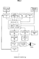
- FIG. 3 illustrates an example of an internal configuration of the head-mounted display 100.
- the respective components will be described.
- a control unit 301 is equipped with read-only memory (ROM) 301A and random access memory (RAM) 301B.
- the ROM 301A stores program code executed by the control unit 301, and various data.
- the control unit 301 by executing a program loaded into the RAM 301B from the ROM 301A or a storage unit 306 (discussed later), controls the display of images, and also centrally controls the operation of the head-mounted display 100 overall.
- the program and data stored in the ROM 301A may be an image display control program for video playback or the like, an interaction control program that enables the user viewing the display image to interact with the real world, identification information unique to the relevant head-mounted display 100, user attribute information for the user using the relevant head-mounted display 100, and the like.
- the input interface (IF) unit 302 is equipped with one or more operating elements on which the user performs an input operation, such as keys, buttons, and switches (none illustrated), receives user instructions via the operating elements, and outputs to the control unit 301. Also, the input interface unit 302 receives user instructions made up of remote control commands received by the remote control receiving unit 303, and outputs to the control unit 301.
- the input interface unit 302 outputs input information such as coordinate data of the touched fingertip position to the control unit 301.
- the touch panel 315 is disposed on the front face of the main body of the head-mounted display 100, directly behind the display image of the display unit 309 (the enlarged virtual image viewed through the virtual image optical unit 310), the user is able to perform touch operations with a sense of touching the display image with his or her fingertip.
- the status information acquisition unit 304 is a function module that acquires status information about the head-mounted display 100 itself or the user wearing the head-mounted display 100.
- the status information acquisition unit 304 may be equipped with various sensors for detecting its own status information, or be configured to acquire status information via a communication unit 305 (discussed later) from external equipment equipped with some or all of such sensors (for example, a smartphone, wristwatch, or some other multi-function terminal being worn by the user).
- the status information acquisition unit 304 acquires information about the position and orientation or information about the orientation of the user's head, for example, in order to track the user's head movements.
- the status information acquisition unit 304 is taken to be a sensor including a three-axis gyro sensor, a three-axis acceleration sensor, and a three-axis geomagnetic sensor, for a total of nine detectable axes, for example.
- the status information acquisition unit 304 may further combine and use the above with one or multiple other sensors such as a Global Positioning System (GPS) sensor, a Doppler sensor, an infrared sensor, or a radio field intensity sensor.
- GPS Global Positioning System
- the status information acquisition unit 304 may further combine and use the acquisition of position and orientation information with information provided by various infrastructure, such as mobile phone base station information or PlaceEngine (registered trademark) information (radio field intensity measurement information from a wireless LAN access point).
- the status information acquisition unit 304 for head movement tracking is built into a head-mounted display 100, but may also be configured by an accessory part of the like that is externally attached to the head-mounted display 100.
- the status information acquisition unit 304 expresses head orientation information in the form of rotation matrices, for example, and transmits the head orientation information to the main head-mounted display 100 by wireless communication such as Bluetooth (registered trademark) communication, or by a high-speed wired interface such as Universal Serial Bus (USB).
- wireless communication such as Bluetooth (registered trademark) communication
- USB Universal Serial Bus
- the status information acquisition unit 304 may also acquire other information as status information about the user wearing the head-mounted display 100, such as the user's operating status (whether or not the user is wearing the head-mounted display 100), the user's behavioral status (a movement status such as being still, walking, or running, gestures made with the hands or fingers, the open/closed status of the eyelids, the gaze direction, and the size of the pupils), the psychological status (such as a degree of impression, a degree of excitement, a degree of alertness, feelings, and emotions, such as whether the user is immersed in or concentrating on viewing the displayed image), as well as the physiological status.
- the user's operating status whether or not the user is wearing the head-mounted display 100
- the user's behavioral status a movement status such as being still, walking, or running, gestures made with the hands or fingers, the open/closed status of the eyelids, the gaze direction, and the size of the pupils
- the psychological status such as a degree of impression, a degree of excitement, a degree of alert
- the status information acquisition unit 304 may also be equipped with various status sensors such as a wear sensor made up of the outward-facing camera 312, a mechanical switch or the like, an inward-facing camera that photographs the user's face, a gyro sensor, an acceleration sensor, a velocity sensor, a pressure sensor, a temperature sensor that senses body temperature or air temperature, a sweat sensor, a pulse sensor, a myoelectric potential sensor, an oculo-electric potential sensor, a brain wave sensor, a breath sensor, and a gas ion concentration sensor, as well as a timer (none illustrated in the drawing).
- a wear sensor made up of the outward-facing camera 312, a mechanical switch or the like
- an inward-facing camera that photographs the user's face
- a gyro sensor an acceleration sensor
- a velocity sensor that senses body temperature or air temperature
- a sweat sensor a pulse sensor
- a myoelectric potential sensor an oculo-electric potential sensor
- the environment information acquisition unit 316 is a function module that acquires information related to the environment surrounding the main body of the relevant head-mounted display 100 or the user wearing the relevant head-mounted display 100.
- the information related to the environment may be sound, air flow, air temperature, air pressure, atmosphere (smoke or fog, electromagnetic waves (ultraviolet light, blue light, radio waves) flooding the relevant head-mounted display 100 or the user, heat rays (infrared), radiation, atmospheric carbon monoxide, carbon dioxide, oxygen, and nitrogenous compounds (nicotine), nitrogen oxides (NO x ) and hydrocarbons (volatile organic compounds (VOC)) floating in the atmosphere or photochemical smog generated by inducing a photochemical reaction in these due to the effect of ultraviolet light, particulate matter, pollen, fine particles such as house dust, and hazardous chemical substances such as asbestos), and other environmental factors.
- VOC volatile organic compounds
- the environment information acquisition unit 316 may be equipped with a sound sensor and an air flow sensor, as well as various types of environmental sensors.
- the microphones and the outward-facing camera 312 discussed earlier may also be included among the environmental sensors.
- the environment information acquisition unit 316 may be configured to acquire environment information via a communication unit 305 (discussed later) from external equipment equipped with some or all of such sensors (for example, a smartphone, wristwatch, or some other multi-function terminal being worn by the user).
- the outward-facing camera 312 is disposed near the center of the front face of the main unit of the head-mounted display 100, for example (see FIG. 1 ), and is able to capture an image of the surroundings.
- the user is taken to be able to adjust the zoom of the outward-facing camera 312 through an input operation via the input interface unit 302, or by pupil magnitude or voice input recognized by a device such as an inward-facing camera or a myoelectric sensor.
- a device such as an inward-facing camera or a myoelectric sensor.
- orientation control in the pan, tilt, and roll directions of the outward-facing camera 312 to match the user's gaze direction acquired by the status information acquisition unit 304, it is possible to capture an image of the user's own gaze, or in other words an image in the user's gaze direction, with the outward-facing camera 312.
- the captured image from the outward-facing camera 312 may be output for display by the display unit 309, and the captured image may also be transmitted from the communication unit 305 or saved
- the outward-facing camera 312 is made up of multiple cameras to enable the outward-facing camera 312 to acquire three-dimensional information about the image of the surroundings by using parallax information.
- simultaneous localization and mapping (SLAM) image recognition may also be used to capture images while moving the camera, compute parallax information using multiple frame images succeeding each other in time (see Patent Literature 3, for example), and acquire three-dimensional information about the image of the surroundings from the computed parallax information.
- SLAM simultaneous localization and mapping
- the outward-facing camera 312 is able to acquire three-dimensional information, and thus may also be used as a distance sensor.
- a distance sensor made up of an inexpensive device such as a position sensitive detector (PSD) that detects a reflected signal from an object, for example, may be used in conjunction with the outward-facing camera 312.
- PSD position sensitive detector
- the outward-facing camera 312 and the distance sensor may be used to detect the position, orientation, and shape of the body of the user wearing the head-mounted display 100.
- the communication unit 305 conducts a communication process with external equipment, as well as modulation/demodulation and coding/decoding processes on communication signals.
- the external equipment may be a content playback device (Blu-ray Disc or DVD player) that supplies viewing content when the user uses the head-mounted display 100, a multi-function terminal such as a smartphone, a game console, or a streaming server.
- the control unit 301 transmits transmission data to external equipment from the communication unit 305.
- the configuration of the communication unit 305 is arbitrary.
- the communication unit 305 may be configured according to a communication scheme used for transmitting and receiving operations with external equipment that acts as a communication peer.
- the communication scheme may be either wired or wireless.
- the communication standard referred to herein may be a standard such as Mobile High-Definition Link (MHL), Universal Serial Bus (USB), High-Definition Multimedia Interface (HDMI; registered trademark), Bluetooth (registered trademark) communication or Bluetooth (registered trademark) Low Energy (BLE) communication, ultra-low-power wireless communication such as ANT, or a mesh network standardized by IEEE 802.11s or the like.
- the communication unit 305 may be a cellular radio transceiver that operates in accordance with an established standard such as Wideband Code Division Multiple Access (W-CDMA) or Long Term Evolution (LTE), for example.
- W-CDMA Wideband Code Division Multiple Access
- LTE Long Term Evolution
- the storage unit 306 is a mass storage device such as a solid-state drive (SSD).
- the storage unit 306 stores application programs executed by the control unit 301, and various data. For example, content viewed by the user using the head-mounted display 100 is stored in the storage unit 306.
- the image processing unit 307 additional conducts signal processing such as image quality correction on an image signal output from the control unit 301, and also converts the image signal to a resolution suited to the screen of the display unit 309. Subsequently, the display driving unit 308 sequentially selects the pixels of the display unit 309 every row while performing line-sequential scanning, and supplies a pixel signal based on the processed image signal.
- the display unit 309 includes a display panel made up of a microdisplay such as organic electro-luminescence (EL) elements or a liquid crystal display, or alternatively, a laser-scanning display such as a retinal scanning display.
- the virtual image optical unit 310 enlarges and projects the display image of the display unit 309, enabling the user to view the display image as an enlarged virtual image.
- the display image output by the display unit 309 may be commercial content (virtual world) supplied from a content playback device (Blu-ray Disc or DVD player), a multi-function terminal such as a smartphone, a game console, or a streaming server, a captured image (real world) from the outward-facing camera 312, or the like.
- a content playback device Blu-ray Disc or DVD player
- a multi-function terminal such as a smartphone, a game console, or a streaming server
- a captured image real world
- the audio processing unit 313 performs audio quality correction and audio amplification on an audio signal output from the control unit 301, and additionally performs signal processing on signals such as an input audio signal. Additionally, the audio input/output unit 314 externally outputs the processed audio, and also accepts audio input from a microphone (described above).
- the head-mounted display 100 as illustrated in FIGS. 1 and 2 is opaque, or in other words, covers the eyes of the wearing user. Additionally, video content such as a movie or images expressed by technology such as computer graphics are displayed on the display unit 309.
- the virtual image optical unit 310 enlarges and projects the display image of the display unit 309, enabling the user to view the display image as an enlarged virtual image having a suitable angle of view, and recreating the sense of being in a movie theater, for example.
- the user is able to have an immersive experience of the virtual world displayed on the display unit 309.
- the head-mounted display 100 when displaying an image of the virtual world such as a movie or computer graphics with the display unit 309, the head-mounted display 100 mixes in an image of the outside world, or in other words the real world, captured with the outward-facing camera 312. Consequently, by looking at the image of the real world mixed in with the image of the virtual world, the user is able to perceive the real world and suitably interact with the real world, thereby making it possible to lessen psychological resistance while also avoiding physical harm due to events such as collisions with objects in the real world.
- the head-mounted display 100 replaces a partial, user-specified region out of the display region of the display unit 309 displaying an image of the virtual world with an image of the real world captured with the outward-facing camera 312 for display.
- the image displayed by the display unit 309 (the image viewed by the user's eyes via the virtual image optical unit 310) is a combination of information about the virtual world, such as playback images of commercial content, and information about the real world captured with the outward-facing camera 312. Consequently, the user is able to grasp the surrounding environment (events occurring in reality in the vicinity of oneself) continuously, without interrupting the state of immersion into the virtual world expressed by the content.
- the displayed image of the real world is basically a live image captured with the outward-facing camera 312, but may also be a recorded image temporarily stored in the storage unit 306.
- the display of an image of the real world in the region specified by the user is temporary
- the entire display region of the display unit 309 may be reverted to the image of the virtual world according to an explicit operation to cancel the region specification by the user.
- the display may be switched from the image of the real world to the image of the virtual world after a fixed time elapses from when the user specified a region, or the display may be reverted to the image of the virtual world gradually (for example, while varying a mixture ratio of the image of the real world and the image of the virtual world).
- the image of the virtual world is reverted according to the elapsing of time because after a fixed time elapses from when the user performed the operation, the user is assumed to not require the display of the real world any more.
- the method by which the user specifies the region in which to display the image of the real world is arbitrary.
- the user may operate buttons included on the input interface unit 302 to specify the region to replace with the real world.
- the region to replace with the real world may be moved up, down, left, and right according to operations on directional keys.
- the region corresponding to a location where the user performed a touch operation with a fingertip on the touch panel 315 may be replaced with the real world.
- a gesture that the user performs using a hand or the like may be captured with the outward-facing camera 312, and a region designated by the gesture may be replaced with the real world.
- the touch panel 315 is disposed on the front face of the main body of the head-mounted display 100, directly behind the display image of the display unit 309 (the enlarged virtual image viewed through the virtual image optical unit 310), the user is able to perform touch operations with a sense of touching the display image with his or her fingertip. More specifically, when a cursor is displayed at a position corresponding to the location where the touch panel 315 was touched, as illustrated in FIG.
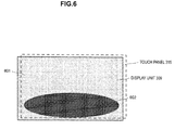
- FIG. 5 illustrates how the user uses a touch panel 315 to specify a region in which to display an image of the real world. While the display unit 309 is displaying only the image of the virtual world, the user moves a fingertip on the touch panel 315 behind the display unit 309, and specifies a desired location 503 at which to display the real world, as indicated by the reference numbers 501 and 502.
- FIG. 6 illustrates how the inside of a region 602 specified by the user operation illustrated in FIG. 5 from an image 601 of the virtual world displayed by the display unit 309 is replaced with the image of the real world captured with the outward-facing camera 312.
- the image displayed by the display unit 309 is a combination of information about the virtual world and information about the real world. Consequently, the user is able to grasp the surrounding environment (events occurring in reality in the vicinity of oneself) continuously, without interrupting the state of immersion into the virtual world expressed by the content.
- FIG. 7 illustrates a functional configuration by which the head-mounted display 100 replaces a partial region of the display region with an image of the real world for display.
- a virtual world image generation unit 701 calculates a virtual world rendering result V to be displayed by the display unit 309, on the basis of information about the virtual world stored in advance in the storage unit 306 or received externally with the communication unit 305, for example.
- a real world image acquisition unit 702 acquires an image I of the real world around the user, on the basis of data such as an image captured with the outward-facing camera 312.
- a region specification unit 703 specifies a region in which to display image information about the real world out of the display screen of the display unit 309, on the basis of a user operation on the touch panel 315 (see FIG. 5 ), an operation on the input interface unit 302, gesture input, or the like.
- a region image generation unit 704 calculates an image R I of the real world and an image R V of the virtual world corresponding to the region specified by the region specification unit 703. Subsequently, an image replacement unit 705 synthesizes an image in which the image R V of the corresponding region of the virtual world rendering result V is replaced by the image R I of the corresponding region of the real world. The synthesized image is displayed on the display unit 309.
- each of the above function blocks 701 to 705 is realized by a program executed by the control unit 301, for example, but may also be configured as dedicated hardware.
- FIG. 8 illustrates an example of the virtual world rendering result V, and the image R V of the corresponding region in the region specified by the user.
- FIG. 9 illustrates an example of the image I of the real world captured by the outward-facing camera 312, and the image R I of the region corresponding to the region specified by the user.
- FIG. 10 illustrates an example of a display image in which the image R V of the corresponding region of the virtual world rendering result V has been replaced by the image R I of the corresponding region of the real world.
- FIG. 11 illustrates, in flowchart format, a processing sequence by which the head-mounted display 100 replaces a partial region of the display region with an image of the real world for display.
- the virtual world image generation unit 701 calculates the virtual world rendering result V (step S1101).
- Information about the virtual world is made available by being stored in advance in the storage unit 306 or by being received externally with the communication unit 305, for example.
- the region specification unit 703 specifies a real world display region on the basis of an operation from the user (step S1102). As discussed above, the user is able to specify the real world display region by performing an operation on the touch panel 315, an operation on the input interface unit 302, gesture input, or the like.
- the real world image acquisition unit 702 acquires an image I of the user's surroundings, or in other words the real world, from data such as an image captured with the outward-facing camera 312 (step S1103).
- the region image generation unit 704 calculates the captured image R I of the real world and the image R V of the virtual world corresponding to the region specified in step S1102 (step S1104).
- the image replacement unit 705 replaces the image R V of the corresponding region of the virtual world rendering result V calculated in step S1101 with the image R I of the corresponding region of the real world, and generates an image in which an image of the real world is mixed into an image of the virtual world (step S1105).
- the generated image is displayed by the display unit 309 (step S1106).
- the display of the image R I of the real world in the region specified by the user is temporary.
- the entire display region of the display unit 309 may be reverted to the image of the virtual world according to an explicit operation to cancel the region specification by the user.
- the display may be switched to the image R V of the virtual world after a fixed time elapses from when the user specified a region, or the display may be reverted to the image R V of the virtual world gradually (for example, while varying a mixture ratio of the image R I of the real world and the image R V of the virtual world).
- the image of the virtual world is reverted according to the elapsing of time because after a fixed time elapses from when the user performed the operation, the user is assumed to not require the display of the real world any more.
- step S107, No when continuing to display the image of the virtual world with the display unit 309 (step S107, No), the process discussed above is returned to step S1101 and repeatedly executed.
- the real world display region is continually updated in step S1102. For example, if the user moves his or her fingertip designating the boundary of the desired region 602 in which to display the real world, in step S1102, the touch panel 315 is able to read the position where the fingertip moved, and enlarge the region 1201 to the region 1202 as illustrated in FIG. 12 , or conversely, reduce the region 1301 to the region 1302 as illustrated in FIG. 13 . If the user wants to know more about conditions in the real world, the region in which to display the image of the real world may be enlarged by an operation like that illustrated in FIG. 12 , whereas if the conditions in the real world become less important, the region in which to display the image of the real world may be reduced by an operation like that illustrated in FIG. 13 to thereby enlarge the region in which to display the virtual world.
- the user becomes able to interact with the real world without diminishing the sense of immersion into the virtual world.
- a user wearing such a head-mounted display 100 is able to lessen his or her psychological resistance against immersing oneself into the virtual world.
- the user is able to reduce the risk of physical harm caused by body movements in the real world, even when immersed in the virtual world.
- the head-mounted display 100 displays an image in which a three-dimensional (3D) model of a specific object existing in the real world is placed inside a three-dimensional virtual world.
- an image of the real world is superimposed onto part of the display image of the virtual world (like picture-in-picture).
- the second embodiment differs in that the entire display image is an image of the virtual world.
- a 3D model corresponding to an object in the real world is displayed as an object inside the image of the virtual world.
- the 3D model is information about the real world, but the object is converted into a 3D model, and thus has a high affinity with the display image of the virtual world.
- the object in the real world is part of the body of the user wearing the head-mounted display 100, such as the right hand, for example.
- three-dimensional models of a variety of objects in the real world including a specific person such as an acquaintance of the user, a specific animal such as a pet, a moving body, or a stationary object, may also be placed in the virtual world and displayed.
- the object to place in the virtual world may be fixed, or be successively selectable by the user.
- the head-mounted display 100 upon detecting an object in the real world using the outward-facing camera 312 and the distance sensor, tracks the detected object, places a three-dimensional model of the detected object in the virtual world, and conducts a rendering process.
- all physical bodies in the real world within a fixed distance from the head-mounted display 100 may be detected as objects automatically, and a three-dimensional model M I of such objects may be placed in the virtual world and displayed.
- a three-dimensional model M I of such objects may be placed in the virtual world and displayed.
- the physical body is detected as an object automatically, and as long as the hand remains within a fixed distance from the head-mounted display 100, the physical body is tracked and a three-dimensional model M I of the physical body is placed in the virtual world and continually displayed. If the hand moves away farther than the fixed distance, the physical body is no longer detected, and the display of the three-dimensional model M I also disappears.
- the transparency may rise gradually with distance and automatically return to the original display of the virtual world only. This is because the display of an object that has moved away farther than the fixed distance is considered to be no longer necessary to the user.
- the image displayed by the display unit 309 (the image viewed by the user's eyes via the virtual image optical unit 310) is a combination of information about the virtual world, such as playback images of commercial content, and a converted three-dimensional model of information about the real world captured with the outward-facing camera 312. Consequently, the user is able to grasp the surrounding environment (events occurring in reality in the vicinity of oneself) continuously, without interrupting the state of immersion into the virtual world expressed by the content.
- the three-dimensional model basically is generated on the basis of an object in the real world appearing in a live image captured with the outward-facing camera 312, but may also be generated on the basis of an object in the real world appearing in a recorded image temporarily stored in the storage unit 306.
- the second embodiment differs by combining information about the virtual world and information about the real world with a three-dimensional rendering process.
- the second embodiment may also combine the functions of a two-dimensional display and a three-dimensional display of the real world.
- the display of an image of the real world in the region corresponding to the location where an object was detected is temporary.
- the three-dimensional model corresponding to the object may be removed from the display image of the virtual world, or the three-dimensional model corresponding to the object in the real world may gradually go transparent (for example, while varying a mixture ratio of the image of the real world and the image of the virtual world) to revert back to the original image of the virtual world only. This is because if the object is no longer visible, the user is considered to longer need the display of the real world.
- the entire display region of the display unit 309 may be reverted to the image of the virtual world according to an explicit operation to cancel the region specification by the user.
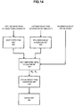
- FIG. 14 illustrates a functional configuration by which the head-mounted display 100 displays an image in which an object existing in the real world has been converted to a three-dimensional model and placed in the virtual world.
- An object detection unit 1401 detects a specific object in the real world, such as part of the user's body, on the basis of a recognition process on a captured image from the outward-facing camera 312, a detection signal from the distance sensor, or the like.
- a specific object in the real world such as part of the user's body
- a detection signal from the distance sensor or the like.
- all physical bodies in the real world within a fixed distance from the head-mounted display 100 may be detected as objects automatically.
- a real world image acquisition unit 1402 acquires an image of the real world, including the object detected by the object detection unit 1401, on the basis of data such as an image captured with the outward-facing camera 312.
- a three-dimensional model calculation unit 1403 generates a three-dimensional model M I of a certain range including the detected object, on the basis of the detection result by the object detection unit 1401 and the image of the real world acquired by the real world image acquisition unit 1402. In addition, the three-dimensional model calculation unit 1403 calculates the region R V of the virtual space V corresponding to the location where the object detection unit 1401 detected the object.
- a virtual world image generation unit 1404 calculates a three-dimensional model M M in which the three-dimensional model M I of the object is placed in the corresponding region R V of the three-dimensional model V of the virtual world, and conducts a rendering process. Subsequently, the rendered image is displayed on the display unit 309.
- each of the above function blocks 1401 to 1404 is realized by a program executed by the control unit 301, for example, but may also be configured as dedicated hardware.
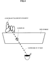
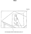
- FIG. 15 illustrates an example of how the object detection unit 1401 detects a specific object such as part of the user's body in the real world, as indicated by the reference number 1501.
- the outward-facing camera 312 captures an image of the real world including the object detected by the object detection unit 1401.
- a PET bottle placed on a table and grasped by the user's right hand in the real world is detected by the object detection unit 1401.
- FIG. 16 illustrates an example of how the three-dimensional model calculation unit 1403 generates a three-dimensional model M I of a certain range including the object detected by the object detection unit 1401, as indicated by the reference number 1601.
- an image M I is generated in which the user's right hand and the PET bottle grasped in the right hand have been converted into a three-dimensional model.
- FIG 16 also illustrates an example of how the three-dimensional model calculation unit 1403 calculates the region R V of the virtual space V corresponding to the location where the object detection unit 1401 detected the object.
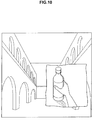
- FIG. 17 illustrates an example of the result of the virtual world image generation unit 1404 calculating and rendering a three-dimensional model M M in which the three-dimensional model M I of the object is placed in the corresponding region R V of the three-dimensional model V of the virtual world.
- an image M I in which the user's right hand and the PET bottle grasped in the right hand have been converted into a three-dimensional model is superimposed onto a three-dimensional image of the virtual space V
- a virtual object does not exist in front of the corresponding region R V in the virtual space V corresponding to the three-dimensional model M I of the object, and thus the entire three-dimensional model M I is displayed as illustrated in FIG. 17 .
- the three-dimensional model M I is displayed obscured behind by the virtual object.
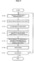
- FIG. 18 illustrates, in flowchart form, a processing sequence by which the head-mounted display 100 displays an image in which a three-dimensional model of an object existing in the real world is placed in the virtual world.
- the object detection unit 1401 detects a specific object in the real world, such as part of the user's body, on the basis of a recognition process on a captured image from the outward-facing camera 312, a detection signal from the distance sensor, or the like (step S1801).
- the object detection unit 1401 may also automatically detect all physical bodies in the real world within a fixed distance from the head-mounted display 100. For example, as the user brings his or her hand holding a physical body such as a cup close to the head-mounted display 100, the physical body is detected as an object automatically and tracked as long as the hand remains within a fixed distance. Also, if the hand moves away farther than the fixed distance, the object detection unit 1401 no longer detects the physical body, and stops tracking.
- the real world image acquisition unit 1402 acquires an image of the real world, including the object detected by the object detection unit 1401, on the basis of data such as an image captured with the outward-facing camera 312 (step S1802).
- the three-dimensional model calculation unit 1403 generates a three-dimensional model M I of a certain range including the detected object, on the basis of the detection result by the object detection unit 1401 and the image of the real world acquired by the real world image acquisition unit 1402 (step S1803).
- the three-dimensional model calculation unit 1403 calculates the region R V of the virtual space V corresponding to the location where the object detection unit 1401 detected the object (step S1804).
- the virtual world image generation unit 1404 calculates a three-dimensional model M M in which a three-dimensional model M I of a certain range including the object is placed in the corresponding region R V of the three-dimensional model V of the virtual world (step S1805), and conducts a process of rendering M M to also appear in 3D (step S1806). Subsequently, the rendered image is displayed on the display unit 309 (step S807).
- step S1808, No when continuing to display the image of the virtual world with the display unit 309 (step S1808, No), the process discussed above is returned to step S1801 and repeatedly executed.
- step S1801 the corresponding region R V in which to place the three-dimensional model M I in the virtual space V is continually updated as the object in the real world moves.
- the boundary may be operated on the condition that the current position of the object overlaps with the boundary between the three-dimensional model M I of the real world and the virtual world V being displayed on the display unit 309.
- a state enabling the boundary to be operated may be activated by recognizing a specific gesture by the user.
- the user becomes able to interact with the real world without diminishing the sense of immersion into the virtual world.
- psychological resistance against immersing oneself into the virtual world may be lessened.
- the user is able to reduce the risk of physical harm caused by body movements in the real world, even when immersed in the virtual world.
- This specification primarily describes an embodiment applying the technology disclosed in this specification to an opaque head-mounted display, but the gist of the technology disclosed in this specification is not limited thereto.
- the technology disclosed in this specification may be applied similarly to various types of image display devices equipped with a function of displaying images of the real world and images of a virtual world, such as a see-through head-mounted display, a head-up display, a camera-equipped smartphone, and a multi-function terminal.
Priority Applications (1)
| Application Number | Priority Date | Filing Date | Title |
|---|---|---|---|
| EP18184698.1A EP3410264B1 (fr) | 2014-01-23 | 2014-11-11 | Dispositif d'affichage d'images et procédé d'affichage d'images |
Applications Claiming Priority (2)
| Application Number | Priority Date | Filing Date | Title |
|---|---|---|---|
| JP2014010582 | 2014-01-23 | ||
| PCT/JP2014/079812 WO2015111283A1 (fr) | 2014-01-23 | 2014-11-11 | Dispositif d'affichage d'images et procédé d'affichage d'images |
Related Child Applications (2)
| Application Number | Title | Priority Date | Filing Date |
|---|---|---|---|
| EP18184698.1A Division EP3410264B1 (fr) | 2014-01-23 | 2014-11-11 | Dispositif d'affichage d'images et procédé d'affichage d'images |
| EP18184698.1A Division-Into EP3410264B1 (fr) | 2014-01-23 | 2014-11-11 | Dispositif d'affichage d'images et procédé d'affichage d'images |
Publications (3)
| Publication Number | Publication Date |
|---|---|
| EP3098689A1 true EP3098689A1 (fr) | 2016-11-30 |
| EP3098689A4 EP3098689A4 (fr) | 2017-09-20 |
| EP3098689B1 EP3098689B1 (fr) | 2019-04-03 |
Family
ID=53681105
Family Applications (2)
| Application Number | Title | Priority Date | Filing Date |
|---|---|---|---|
| EP18184698.1A Active EP3410264B1 (fr) | 2014-01-23 | 2014-11-11 | Dispositif d'affichage d'images et procédé d'affichage d'images |
| EP14879372.2A Active EP3098689B1 (fr) | 2014-01-23 | 2014-11-11 | Dispositif d'affichage d'images et procédé d'affichage d'images |
Family Applications Before (1)
| Application Number | Title | Priority Date | Filing Date |
|---|---|---|---|
| EP18184698.1A Active EP3410264B1 (fr) | 2014-01-23 | 2014-11-11 | Dispositif d'affichage d'images et procédé d'affichage d'images |
Country Status (6)
| Country | Link |
|---|---|
| US (1) | US10134189B2 (fr) |
| EP (2) | EP3410264B1 (fr) |
| JP (1) | JP6524917B2 (fr) |
| KR (1) | KR102332326B1 (fr) |
| CN (2) | CN105992986B (fr) |
| WO (1) | WO2015111283A1 (fr) |
Cited By (5)
| Publication number | Priority date | Publication date | Assignee | Title |
|---|---|---|---|---|
| WO2017189699A1 (fr) * | 2016-04-27 | 2017-11-02 | Rovi Guides, Inc. | Procédés et systèmes permettant d'afficher un contenu supplémentaire sur un affichage tête haute affichant un environnement de réalité virtuelle |
| EP3281058A4 (fr) * | 2015-08-31 | 2018-04-11 | Samsung Electronics Co., Ltd. | Appareil d'affichage de réalité virtuelle et procédé d'affichage associé |
| EP3211513A4 (fr) * | 2014-10-22 | 2018-07-25 | Sony Interactive Entertainment Inc. | Visiocasque, terminal d'informations mobile, dispositif de traitement d'images, programme de commande d'affichage et procédé de commande d'affichage |
| EP3407304A4 (fr) * | 2016-01-20 | 2019-08-21 | Sony Interactive Entertainment Inc. | Dispositif de traitement d'informations et procédé de présentation de guide d'utilisateur |
| EP3926588A1 (fr) | 2020-06-19 | 2021-12-22 | Alpine Electronics, Inc. | Appareil d'affichage d'images et procédé d'affichage de données d'image sur un dispositif d'affichage rv, en particulier disposé dans un véhicule |
Families Citing this family (42)
| Publication number | Priority date | Publication date | Assignee | Title |
|---|---|---|---|---|
| JP6138566B2 (ja) * | 2013-04-24 | 2017-05-31 | 川崎重工業株式会社 | 部品取付作業支援システムおよび部品取付方法 |
| EP2996017B1 (fr) | 2014-09-11 | 2022-05-11 | Nokia Technologies Oy | Procédé, appareil et programme informatique permettant d'afficher une image d'un clavier physique sur un dispositif d'affichage montable sur la tête |
| JP6618260B2 (ja) * | 2015-02-19 | 2019-12-11 | キヤノン株式会社 | 情報処理装置、情報処理方法、プログラム |
| CN105659146A (zh) * | 2015-05-29 | 2016-06-08 | 深圳市柔宇科技有限公司 | 显示调节的方法及头戴式显示设备 |
| US20170061696A1 (en) * | 2015-08-31 | 2017-03-02 | Samsung Electronics Co., Ltd. | Virtual reality display apparatus and display method thereof |
| JP6232649B2 (ja) * | 2016-02-18 | 2017-11-22 | 国立大学法人名古屋大学 | 仮想空間表示システム |
| JP6790417B2 (ja) * | 2016-03-31 | 2020-11-25 | ソニー株式会社 | 情報処理装置及び情報処理サーバ |
| US10025376B2 (en) | 2016-04-27 | 2018-07-17 | Rovi Guides, Inc. | Methods and systems for displaying additional content on a heads up display displaying a virtual reality environment |
| US9851792B2 (en) | 2016-04-27 | 2017-12-26 | Rovi Guides, Inc. | Methods and systems for displaying additional content on a heads up display displaying a virtual reality environment |
| CN106200881A (zh) * | 2016-06-29 | 2016-12-07 | 乐视控股(北京)有限公司 | 一种数据展示方法及装置与虚拟现实设备 |
| US10191541B2 (en) * | 2016-06-30 | 2019-01-29 | Sony Interactive Entertainment Inc. | Augmenting virtual reality content with real world content |
| CN106383578B (zh) * | 2016-09-13 | 2020-02-04 | 网易(杭州)网络有限公司 | 虚拟现实系统、虚拟现实交互装置及方法 |
| US10642345B2 (en) * | 2016-10-18 | 2020-05-05 | Raytheon Company | Avionics maintenance training |
| JPWO2018101227A1 (ja) * | 2016-11-29 | 2019-10-31 | シャープ株式会社 | 表示制御装置、ヘッドマウントディスプレイ、表示制御装置の制御方法、および制御プログラム |
| CN106774869B (zh) * | 2016-12-08 | 2020-05-19 | 广州大西洲科技有限公司 | 一种实现虚拟现实的方法、装置及虚拟现实头盔 |
| WO2018112838A1 (fr) * | 2016-12-22 | 2018-06-28 | 深圳市柔宇科技有限公司 | Appareil d'affichage tête haute, et procédé procurant une aide visuelle de celui-ci |
| WO2018135057A1 (fr) * | 2017-01-20 | 2018-07-26 | ソニー株式会社 | Dispositif de traitement d'informations, procédé de traitement d'informations, et programme |
| CN108496107A (zh) * | 2017-03-28 | 2018-09-04 | 深圳市柔宇科技有限公司 | 头戴式显示设备及其显示切换方法 |
| CN107172414A (zh) * | 2017-04-20 | 2017-09-15 | 北京安云世纪科技有限公司 | 一种虚拟现实头戴显示器设备及其处理信息的方法 |
| GB2555501B (en) * | 2017-05-04 | 2019-08-28 | Sony Interactive Entertainment Europe Ltd | Head mounted display and method |
| CN107179876B (zh) * | 2017-06-30 | 2023-08-25 | 吴少乔 | 基于虚拟现实系统的人机交互装置 |
| KR102077665B1 (ko) * | 2017-09-26 | 2020-04-07 | 에이케이엔코리아 주식회사 | 혼합 현실에서의 가상 모바일 단말 구현 시스템 및 이의 제어 방법 |
| KR102552403B1 (ko) | 2017-09-29 | 2023-07-07 | 애플 인크. | 물리적 경계 검출 |
| US11622153B2 (en) | 2017-10-04 | 2023-04-04 | Interdigital Madison Patent Holdings, Sas | Customized 360-degree media viewing |
| JP2021043476A (ja) * | 2017-12-26 | 2021-03-18 | 株式会社Nttドコモ | 情報処理装置 |
| DE102018207653A1 (de) * | 2018-05-16 | 2019-11-21 | Siemens Aktiengesellschaft | Anzeigegerät zum Darstellen virtueller Realität mit einer berührungsempfindlichen Bedieneinheit; Anzeigesystem; Bediensystem |
| US20190385372A1 (en) * | 2018-06-15 | 2019-12-19 | Microsoft Technology Licensing, Llc | Positioning a virtual reality passthrough region at a known distance |
| US10600246B2 (en) * | 2018-06-15 | 2020-03-24 | Microsoft Technology Licensing, Llc | Pinning virtual reality passthrough regions to real-world locations |
| US10520739B1 (en) * | 2018-07-11 | 2019-12-31 | Valve Corporation | Dynamic panel masking |
| JP6739847B2 (ja) * | 2018-09-12 | 2020-08-12 | 株式会社アルファコード | 画像表示制御装置および画像表示制御用プログラム |
| US10776954B2 (en) | 2018-10-08 | 2020-09-15 | Microsoft Technology Licensing, Llc | Real-world anchor in a virtual-reality environment |
| US20200111256A1 (en) * | 2018-10-08 | 2020-04-09 | Microsoft Technology Licensing, Llc | Real-world anchor in a virtual-reality environment |
| KR102145852B1 (ko) * | 2018-12-14 | 2020-08-19 | (주)이머시브캐스트 | 카메라 기반의 혼합현실 글래스 장치 및 혼합현실 디스플레이 방법 |
| DE102019135676A1 (de) * | 2018-12-26 | 2020-07-02 | Htc Corporation | Objektverfolgungssystem und objektverfolgungsverfahren |
| US11064255B2 (en) * | 2019-01-30 | 2021-07-13 | Oohms Ny Llc | System and method of tablet-based distribution of digital media content |
| US11265487B2 (en) * | 2019-06-05 | 2022-03-01 | Mediatek Inc. | Camera view synthesis on head-mounted display for virtual reality and augmented reality |
| WO2021048985A1 (fr) * | 2019-09-12 | 2021-03-18 | 株式会社ソニー・インタラクティブエンタテインメント | Dispositif de traitement d'image, procédé de traitement d'image et programme |
| US11842449B2 (en) * | 2019-09-26 | 2023-12-12 | Apple Inc. | Presenting an environment based on user movement |
| JP7023005B2 (ja) * | 2019-10-24 | 2022-02-21 | 克己 横道 | 情報処理システム、情報処理方法およびプログラム |
| JP7127659B2 (ja) | 2020-02-07 | 2022-08-30 | カシオ計算機株式会社 | 情報処理装置、仮想・現実合成システム、学習済みモデルの生成方法、情報処理装置に実行させる方法、プログラム |
| KR102543899B1 (ko) * | 2020-08-27 | 2023-06-20 | 네이버랩스 주식회사 | 헤드업 디스플레이 및 그 제어방법 |
| US11595636B1 (en) * | 2021-08-23 | 2023-02-28 | At&T Intellectual Property I, L.P. | Enhanced emotive engagement with volumetric content |
Family Cites Families (18)
| Publication number | Priority date | Publication date | Assignee | Title |
|---|---|---|---|---|
| GB2377147A (en) * | 2001-06-27 | 2002-12-31 | Nokia Corp | A virtual reality user interface |
| JP4136420B2 (ja) * | 2002-03-29 | 2008-08-20 | キヤノン株式会社 | 情報処理方法および装置 |
| JP4434890B2 (ja) * | 2004-09-06 | 2010-03-17 | キヤノン株式会社 | 画像合成方法及び装置 |
| JP4724476B2 (ja) * | 2004-09-07 | 2011-07-13 | キヤノン株式会社 | 情報処理方法及び装置 |
| US20060050070A1 (en) * | 2004-09-07 | 2006-03-09 | Canon Kabushiki Kaisha | Information processing apparatus and method for presenting image combined with virtual image |
| JP2008096868A (ja) | 2006-10-16 | 2008-04-24 | Sony Corp | 撮像表示装置、撮像表示方法 |
| JP5380789B2 (ja) | 2007-06-06 | 2014-01-08 | ソニー株式会社 | 情報処理装置、および情報処理方法、並びにコンピュータ・プログラム |
| US8964298B2 (en) * | 2010-02-28 | 2015-02-24 | Microsoft Corporation | Video display modification based on sensor input for a see-through near-to-eye display |
| JP5434848B2 (ja) | 2010-08-18 | 2014-03-05 | ソニー株式会社 | 表示装置 |
| US20120050140A1 (en) * | 2010-08-25 | 2012-03-01 | Border John N | Head-mounted display control |
| US20120113223A1 (en) * | 2010-11-05 | 2012-05-10 | Microsoft Corporation | User Interaction in Augmented Reality |
| JP2012141461A (ja) * | 2010-12-29 | 2012-07-26 | Sony Corp | ヘッド・マウント・ディスプレイ |
| KR20130067450A (ko) * | 2011-12-14 | 2013-06-24 | 한국전자통신연구원 | 현장적용형 증강현실 기반 작업 가이드용 모듈 일체형 안전모 장치 및 이를 이용한 응용 서비스 제공방법 |
| JP5938977B2 (ja) | 2012-03-23 | 2016-06-22 | ソニー株式会社 | ヘッドマウントディスプレイ及び手術システム |
| US9116666B2 (en) * | 2012-06-01 | 2015-08-25 | Microsoft Technology Licensing, Llc | Gesture based region identification for holograms |
| JP5580855B2 (ja) * | 2012-06-12 | 2014-08-27 | 株式会社ソニー・コンピュータエンタテインメント | 障害物回避装置および障害物回避方法 |
| JP5953963B2 (ja) | 2012-06-13 | 2016-07-20 | ソニー株式会社 | 頭部装着型映像表示装置 |
| CN103489214A (zh) * | 2013-09-10 | 2014-01-01 | 北京邮电大学 | 增强现实系统中基于虚拟模型预处理的虚实遮挡处理方法 |
-
2014
- 2014-11-11 US US15/038,950 patent/US10134189B2/en active Active
- 2014-11-11 EP EP18184698.1A patent/EP3410264B1/fr active Active
- 2014-11-11 CN CN201480064167.2A patent/CN105992986B/zh active Active
- 2014-11-11 WO PCT/JP2014/079812 patent/WO2015111283A1/fr active Application Filing
- 2014-11-11 EP EP14879372.2A patent/EP3098689B1/fr active Active
- 2014-11-11 KR KR1020167013247A patent/KR102332326B1/ko active IP Right Grant
- 2014-11-11 CN CN201910107486.1A patent/CN109828671B/zh active Active
- 2014-11-11 JP JP2015558739A patent/JP6524917B2/ja active Active
Cited By (8)
| Publication number | Priority date | Publication date | Assignee | Title |
|---|---|---|---|---|
| EP3211513A4 (fr) * | 2014-10-22 | 2018-07-25 | Sony Interactive Entertainment Inc. | Visiocasque, terminal d'informations mobile, dispositif de traitement d'images, programme de commande d'affichage et procédé de commande d'affichage |
| US10379605B2 (en) | 2014-10-22 | 2019-08-13 | Sony Interactive Entertainment Inc. | Head mounted display, mobile information terminal, image processing apparatus, display control program, display control method, and display system |
| US10620699B2 (en) | 2014-10-22 | 2020-04-14 | Sony Interactive Entertainment Inc. | Head mounted display, mobile information terminal, image processing apparatus, display control program, display control method, and display system |
| EP3281058A4 (fr) * | 2015-08-31 | 2018-04-11 | Samsung Electronics Co., Ltd. | Appareil d'affichage de réalité virtuelle et procédé d'affichage associé |
| EP3407304A4 (fr) * | 2016-01-20 | 2019-08-21 | Sony Interactive Entertainment Inc. | Dispositif de traitement d'informations et procédé de présentation de guide d'utilisateur |
| WO2017189699A1 (fr) * | 2016-04-27 | 2017-11-02 | Rovi Guides, Inc. | Procédés et systèmes permettant d'afficher un contenu supplémentaire sur un affichage tête haute affichant un environnement de réalité virtuelle |
| EP3457251A1 (fr) * | 2016-04-27 | 2019-03-20 | Rovi Guides, Inc. | Procédés et systèmes permettant d'afficher un contenu supplémentaire sur un affichage tête haute affichant un environnement de réalité virtuelle |
| EP3926588A1 (fr) | 2020-06-19 | 2021-12-22 | Alpine Electronics, Inc. | Appareil d'affichage d'images et procédé d'affichage de données d'image sur un dispositif d'affichage rv, en particulier disposé dans un véhicule |
Also Published As
| Publication number | Publication date |
|---|---|
| CN109828671A (zh) | 2019-05-31 |
| EP3410264A1 (fr) | 2018-12-05 |
| US20160379413A1 (en) | 2016-12-29 |
| KR102332326B1 (ko) | 2021-11-30 |
| CN105992986A (zh) | 2016-10-05 |
| KR20160111904A (ko) | 2016-09-27 |
| EP3098689A4 (fr) | 2017-09-20 |
| JPWO2015111283A1 (ja) | 2017-03-23 |
| JP6524917B2 (ja) | 2019-06-05 |
| CN105992986B (zh) | 2019-03-12 |
| US10134189B2 (en) | 2018-11-20 |
| WO2015111283A1 (fr) | 2015-07-30 |
| EP3098689B1 (fr) | 2019-04-03 |
| EP3410264B1 (fr) | 2020-08-26 |
| CN109828671B (zh) | 2022-02-22 |
Similar Documents
| Publication | Publication Date | Title |
|---|---|---|
| EP3098689B1 (fr) | Dispositif d'affichage d'images et procédé d'affichage d'images | |
| JP6079614B2 (ja) | 画像表示装置及び画像表示方法 | |
| US10356398B2 (en) | Method for capturing virtual space and electronic device using the same | |
| JP6525010B2 (ja) | 情報処理装置及び情報処理方法、並びに画像表示システム | |
| US20170186236A1 (en) | Image display device, image display method, and computer program | |
| JP6217747B2 (ja) | 情報処理装置及び情報処理方法 | |
| US11170580B2 (en) | Information processing device, information processing method, and recording medium | |
| US9886086B2 (en) | Gesture-based reorientation and navigation of a virtual reality (VR) interface | |
| US20150355463A1 (en) | Image display apparatus, image display method, and image display system | |
| JP6822410B2 (ja) | 情報処理システム及び情報処理方法 | |
| WO2017064926A1 (fr) | Dispositif de traitement d'information et procédé de traitement d'information | |
| US20230221833A1 (en) | Methods for displaying user interface elements relative to media content | |
| US20240061547A1 (en) | Devices, Methods, and Graphical User Interfaces for Improving Accessibility of Interactions with Three-Dimensional Environments | |
| US20240103684A1 (en) | Methods for displaying objects relative to virtual surfaces | |
| WO2024054433A2 (fr) | Dispositifs, procédés et interfaces utilisateur graphiques pour commander des avatars dans des environnements tridimensionnels | |
| WO2024039666A1 (fr) | Dispositifs, procédés et interfaces utilisateur graphiques pour améliorer l'accessibilité d'interactions avec des environnements tridimensionnels |
Legal Events
| Date | Code | Title | Description |
|---|---|---|---|
| PUAI | Public reference made under article 153(3) epc to a published international application that has entered the european phase |
Free format text: ORIGINAL CODE: 0009012 |
|
| 17P | Request for examination filed |
Effective date: 20160523 |
|
| AK | Designated contracting states |
Kind code of ref document: A1 Designated state(s): AL AT BE BG CH CY CZ DE DK EE ES FI FR GB GR HR HU IE IS IT LI LT LU LV MC MK MT NL NO PL PT RO RS SE SI SK SM TR |
|
| AX | Request for extension of the european patent |
Extension state: BA ME |
|
| DAX | Request for extension of the european patent (deleted) | ||
| RIC1 | Information provided on ipc code assigned before grant |
Ipc: G02B 27/01 20060101ALI20170510BHEP Ipc: G06F 3/0488 20130101ALI20170510BHEP Ipc: G09G 3/00 20060101ALI20170510BHEP Ipc: G06F 3/041 20060101ALI20170510BHEP Ipc: H04N 5/64 20060101ALI20170510BHEP Ipc: G09G 5/14 20060101ALI20170510BHEP Ipc: G06T 19/20 20110101ALI20170510BHEP Ipc: G06T 19/00 20110101ALI20170510BHEP Ipc: G09G 5/36 20060101ALI20170510BHEP Ipc: G09G 5/00 20060101ALI20170510BHEP Ipc: G06F 3/01 20060101AFI20170510BHEP Ipc: G09G 5/377 20060101ALI20170510BHEP |
|
| A4 | Supplementary search report drawn up and despatched |
Effective date: 20170818 |
|
| RIC1 | Information provided on ipc code assigned before grant |
Ipc: G09G 5/377 20060101ALI20170811BHEP Ipc: G06T 19/00 20110101ALI20170811BHEP Ipc: G06T 19/20 20110101ALI20170811BHEP Ipc: G09G 5/00 20060101ALI20170811BHEP Ipc: G09G 5/36 20060101ALI20170811BHEP Ipc: G02B 27/01 20060101ALI20170811BHEP Ipc: G06F 3/01 20060101AFI20170811BHEP Ipc: G09G 3/00 20060101ALI20170811BHEP Ipc: G06F 3/0488 20130101ALI20170811BHEP Ipc: G09G 5/14 20060101ALI20170811BHEP Ipc: G06F 3/041 20060101ALI20170811BHEP Ipc: H04N 5/64 20060101ALI20170811BHEP |
|
| STAA | Information on the status of an ep patent application or granted ep patent |
Free format text: STATUS: EXAMINATION IS IN PROGRESS |
|
| 17Q | First examination report despatched |
Effective date: 20180529 |
|
| GRAP | Despatch of communication of intention to grant a patent |
Free format text: ORIGINAL CODE: EPIDOSNIGR1 |
|
| STAA | Information on the status of an ep patent application or granted ep patent |
Free format text: STATUS: GRANT OF PATENT IS INTENDED |
|
| INTG | Intention to grant announced |
Effective date: 20181025 |
|
| GRAS | Grant fee paid |
Free format text: ORIGINAL CODE: EPIDOSNIGR3 |
|
| GRAA | (expected) grant |
Free format text: ORIGINAL CODE: 0009210 |
|
| STAA | Information on the status of an ep patent application or granted ep patent |
Free format text: STATUS: THE PATENT HAS BEEN GRANTED |
|
| AK | Designated contracting states |
Kind code of ref document: B1 Designated state(s): AL AT BE BG CH CY CZ DE DK EE ES FI FR GB GR HR HU IE IS IT LI LT LU LV MC MK MT NL NO PL PT RO RS SE SI SK SM TR |
|
| REG | Reference to a national code |
Ref country code: GB Ref legal event code: FG4D |
|
| REG | Reference to a national code |
Ref country code: CH Ref legal event code: EP Ref country code: AT Ref legal event code: REF Ref document number: 1116536 Country of ref document: AT Kind code of ref document: T Effective date: 20190415 |
|
| REG | Reference to a national code |
Ref country code: DE Ref legal event code: R096 Ref document number: 602014044211 Country of ref document: DE |
|
| REG | Reference to a national code |
Ref country code: IE Ref legal event code: FG4D |
|
| REG | Reference to a national code |
Ref country code: NL Ref legal event code: MP Effective date: 20190403 |
|
| REG | Reference to a national code |
Ref country code: LT Ref legal event code: MG4D |
|
| REG | Reference to a national code |
Ref country code: AT Ref legal event code: MK05 Ref document number: 1116536 Country of ref document: AT Kind code of ref document: T Effective date: 20190403 |
|
| PG25 | Lapsed in a contracting state [announced via postgrant information from national office to epo] |
Ref country code: NL Free format text: LAPSE BECAUSE OF FAILURE TO SUBMIT A TRANSLATION OF THE DESCRIPTION OR TO PAY THE FEE WITHIN THE PRESCRIBED TIME-LIMIT Effective date: 20190403 |
|
| PG25 | Lapsed in a contracting state [announced via postgrant information from national office to epo] |
Ref country code: FI Free format text: LAPSE BECAUSE OF FAILURE TO SUBMIT A TRANSLATION OF THE DESCRIPTION OR TO PAY THE FEE WITHIN THE PRESCRIBED TIME-LIMIT Effective date: 20190403 Ref country code: CZ Free format text: LAPSE BECAUSE OF FAILURE TO SUBMIT A TRANSLATION OF THE DESCRIPTION OR TO PAY THE FEE WITHIN THE PRESCRIBED TIME-LIMIT Effective date: 20190403 Ref country code: NO Free format text: LAPSE BECAUSE OF FAILURE TO SUBMIT A TRANSLATION OF THE DESCRIPTION OR TO PAY THE FEE WITHIN THE PRESCRIBED TIME-LIMIT Effective date: 20190703 Ref country code: SE Free format text: LAPSE BECAUSE OF FAILURE TO SUBMIT A TRANSLATION OF THE DESCRIPTION OR TO PAY THE FEE WITHIN THE PRESCRIBED TIME-LIMIT Effective date: 20190403 Ref country code: AL Free format text: LAPSE BECAUSE OF FAILURE TO SUBMIT A TRANSLATION OF THE DESCRIPTION OR TO PAY THE FEE WITHIN THE PRESCRIBED TIME-LIMIT Effective date: 20190403 Ref country code: PT Free format text: LAPSE BECAUSE OF FAILURE TO SUBMIT A TRANSLATION OF THE DESCRIPTION OR TO PAY THE FEE WITHIN THE PRESCRIBED TIME-LIMIT Effective date: 20190803 Ref country code: LT Free format text: LAPSE BECAUSE OF FAILURE TO SUBMIT A TRANSLATION OF THE DESCRIPTION OR TO PAY THE FEE WITHIN THE PRESCRIBED TIME-LIMIT Effective date: 20190403 Ref country code: ES Free format text: LAPSE BECAUSE OF FAILURE TO SUBMIT A TRANSLATION OF THE DESCRIPTION OR TO PAY THE FEE WITHIN THE PRESCRIBED TIME-LIMIT Effective date: 20190403 Ref country code: HR Free format text: LAPSE BECAUSE OF FAILURE TO SUBMIT A TRANSLATION OF THE DESCRIPTION OR TO PAY THE FEE WITHIN THE PRESCRIBED TIME-LIMIT Effective date: 20190403 |
|
| PG25 | Lapsed in a contracting state [announced via postgrant information from national office to epo] |
Ref country code: GR Free format text: LAPSE BECAUSE OF FAILURE TO SUBMIT A TRANSLATION OF THE DESCRIPTION OR TO PAY THE FEE WITHIN THE PRESCRIBED TIME-LIMIT Effective date: 20190704 Ref country code: BG Free format text: LAPSE BECAUSE OF FAILURE TO SUBMIT A TRANSLATION OF THE DESCRIPTION OR TO PAY THE FEE WITHIN THE PRESCRIBED TIME-LIMIT Effective date: 20190703 Ref country code: PL Free format text: LAPSE BECAUSE OF FAILURE TO SUBMIT A TRANSLATION OF THE DESCRIPTION OR TO PAY THE FEE WITHIN THE PRESCRIBED TIME-LIMIT Effective date: 20190403 Ref country code: LV Free format text: LAPSE BECAUSE OF FAILURE TO SUBMIT A TRANSLATION OF THE DESCRIPTION OR TO PAY THE FEE WITHIN THE PRESCRIBED TIME-LIMIT Effective date: 20190403 Ref country code: RS Free format text: LAPSE BECAUSE OF FAILURE TO SUBMIT A TRANSLATION OF THE DESCRIPTION OR TO PAY THE FEE WITHIN THE PRESCRIBED TIME-LIMIT Effective date: 20190403 |
|
| PG25 | Lapsed in a contracting state [announced via postgrant information from national office to epo] |
Ref country code: AT Free format text: LAPSE BECAUSE OF FAILURE TO SUBMIT A TRANSLATION OF THE DESCRIPTION OR TO PAY THE FEE WITHIN THE PRESCRIBED TIME-LIMIT Effective date: 20190403 Ref country code: IS Free format text: LAPSE BECAUSE OF FAILURE TO SUBMIT A TRANSLATION OF THE DESCRIPTION OR TO PAY THE FEE WITHIN THE PRESCRIBED TIME-LIMIT Effective date: 20190803 |
|
| REG | Reference to a national code |
Ref country code: DE Ref legal event code: R097 Ref document number: 602014044211 Country of ref document: DE |
|
| PG25 | Lapsed in a contracting state [announced via postgrant information from national office to epo] |
Ref country code: RO Free format text: LAPSE BECAUSE OF FAILURE TO SUBMIT A TRANSLATION OF THE DESCRIPTION OR TO PAY THE FEE WITHIN THE PRESCRIBED TIME-LIMIT Effective date: 20190403 Ref country code: EE Free format text: LAPSE BECAUSE OF FAILURE TO SUBMIT A TRANSLATION OF THE DESCRIPTION OR TO PAY THE FEE WITHIN THE PRESCRIBED TIME-LIMIT Effective date: 20190403 Ref country code: DK Free format text: LAPSE BECAUSE OF FAILURE TO SUBMIT A TRANSLATION OF THE DESCRIPTION OR TO PAY THE FEE WITHIN THE PRESCRIBED TIME-LIMIT Effective date: 20190403 Ref country code: SK Free format text: LAPSE BECAUSE OF FAILURE TO SUBMIT A TRANSLATION OF THE DESCRIPTION OR TO PAY THE FEE WITHIN THE PRESCRIBED TIME-LIMIT Effective date: 20190403 |
|
| PLBE | No opposition filed within time limit |
Free format text: ORIGINAL CODE: 0009261 |
|
| STAA | Information on the status of an ep patent application or granted ep patent |
Free format text: STATUS: NO OPPOSITION FILED WITHIN TIME LIMIT |
|
| PG25 | Lapsed in a contracting state [announced via postgrant information from national office to epo] |
Ref country code: SM Free format text: LAPSE BECAUSE OF FAILURE TO SUBMIT A TRANSLATION OF THE DESCRIPTION OR TO PAY THE FEE WITHIN THE PRESCRIBED TIME-LIMIT Effective date: 20190403 |
|
| 26N | No opposition filed |
Effective date: 20200106 |
|
| PG25 | Lapsed in a contracting state [announced via postgrant information from national office to epo] |
Ref country code: TR Free format text: LAPSE BECAUSE OF FAILURE TO SUBMIT A TRANSLATION OF THE DESCRIPTION OR TO PAY THE FEE WITHIN THE PRESCRIBED TIME-LIMIT Effective date: 20190403 |
|
| PG25 | Lapsed in a contracting state [announced via postgrant information from national office to epo] |
Ref country code: SI Free format text: LAPSE BECAUSE OF FAILURE TO SUBMIT A TRANSLATION OF THE DESCRIPTION OR TO PAY THE FEE WITHIN THE PRESCRIBED TIME-LIMIT Effective date: 20190403 |
|
| REG | Reference to a national code |
Ref country code: CH Ref legal event code: PL |
|
| PG25 | Lapsed in a contracting state [announced via postgrant information from national office to epo] |
Ref country code: CH Free format text: LAPSE BECAUSE OF NON-PAYMENT OF DUE FEES Effective date: 20191130 Ref country code: LI Free format text: LAPSE BECAUSE OF NON-PAYMENT OF DUE FEES Effective date: 20191130 Ref country code: LU Free format text: LAPSE BECAUSE OF NON-PAYMENT OF DUE FEES Effective date: 20191111 Ref country code: MC Free format text: LAPSE BECAUSE OF FAILURE TO SUBMIT A TRANSLATION OF THE DESCRIPTION OR TO PAY THE FEE WITHIN THE PRESCRIBED TIME-LIMIT Effective date: 20190403 |
|
| REG | Reference to a national code |
Ref country code: BE Ref legal event code: MM Effective date: 20191130 |
|
| GBPC | Gb: european patent ceased through non-payment of renewal fee |
Effective date: 20191111 |
|
| PG25 | Lapsed in a contracting state [announced via postgrant information from national office to epo] |
Ref country code: GB Free format text: LAPSE BECAUSE OF NON-PAYMENT OF DUE FEES Effective date: 20191111 Ref country code: IE Free format text: LAPSE BECAUSE OF NON-PAYMENT OF DUE FEES Effective date: 20191111 |
|
| PG25 | Lapsed in a contracting state [announced via postgrant information from national office to epo] |
Ref country code: BE Free format text: LAPSE BECAUSE OF NON-PAYMENT OF DUE FEES Effective date: 20191130 |
|
| PG25 | Lapsed in a contracting state [announced via postgrant information from national office to epo] |
Ref country code: CY Free format text: LAPSE BECAUSE OF FAILURE TO SUBMIT A TRANSLATION OF THE DESCRIPTION OR TO PAY THE FEE WITHIN THE PRESCRIBED TIME-LIMIT Effective date: 20190403 |
|
| PG25 | Lapsed in a contracting state [announced via postgrant information from national office to epo] |
Ref country code: MT Free format text: LAPSE BECAUSE OF FAILURE TO SUBMIT A TRANSLATION OF THE DESCRIPTION OR TO PAY THE FEE WITHIN THE PRESCRIBED TIME-LIMIT Effective date: 20190403 Ref country code: HU Free format text: LAPSE BECAUSE OF FAILURE TO SUBMIT A TRANSLATION OF THE DESCRIPTION OR TO PAY THE FEE WITHIN THE PRESCRIBED TIME-LIMIT; INVALID AB INITIO Effective date: 20141111 |
|
| PG25 | Lapsed in a contracting state [announced via postgrant information from national office to epo] |
Ref country code: MK Free format text: LAPSE BECAUSE OF FAILURE TO SUBMIT A TRANSLATION OF THE DESCRIPTION OR TO PAY THE FEE WITHIN THE PRESCRIBED TIME-LIMIT Effective date: 20190403 |
|
| P01 | Opt-out of the competence of the unified patent court (upc) registered |
Effective date: 20230527 |
|
| PGFP | Annual fee paid to national office [announced via postgrant information from national office to epo] |
Ref country code: IT Payment date: 20231019 Year of fee payment: 10 Ref country code: FR Payment date: 20231019 Year of fee payment: 10 Ref country code: DE Payment date: 20231019 Year of fee payment: 10 |