EP2996017B1 - Procédé, appareil et programme informatique permettant d'afficher une image d'un clavier physique sur un dispositif d'affichage montable sur la tête - Google Patents
Procédé, appareil et programme informatique permettant d'afficher une image d'un clavier physique sur un dispositif d'affichage montable sur la tête Download PDFInfo
- Publication number
- EP2996017B1 EP2996017B1 EP14184455.5A EP14184455A EP2996017B1 EP 2996017 B1 EP2996017 B1 EP 2996017B1 EP 14184455 A EP14184455 A EP 14184455A EP 2996017 B1 EP2996017 B1 EP 2996017B1
- Authority
- EP
- European Patent Office
- Prior art keywords
- real world
- user
- display
- view
- head mountable
- Prior art date
- Legal status (The legal status is an assumption and is not a legal conclusion. Google has not performed a legal analysis and makes no representation as to the accuracy of the status listed.)
- Active
Links
- 238000000034 method Methods 0.000 title claims description 45
- 238000004590 computer program Methods 0.000 title claims description 34
- 230000004044 response Effects 0.000 claims description 11
- 238000001514 detection method Methods 0.000 claims description 6
- 238000012544 monitoring process Methods 0.000 claims description 2
- 230000001131 transforming effect Effects 0.000 claims 1
- 210000003128 head Anatomy 0.000 description 62
- 230000006870 function Effects 0.000 description 26
- 230000015654 memory Effects 0.000 description 14
- 230000003993 interaction Effects 0.000 description 8
- 238000004891 communication Methods 0.000 description 7
- 230000008569 process Effects 0.000 description 6
- 238000012545 processing Methods 0.000 description 6
- 230000003190 augmentative effect Effects 0.000 description 4
- 238000003384 imaging method Methods 0.000 description 3
- 230000007246 mechanism Effects 0.000 description 3
- 230000000007 visual effect Effects 0.000 description 3
- 230000008901 benefit Effects 0.000 description 2
- 239000002131 composite material Substances 0.000 description 2
- 238000010586 diagram Methods 0.000 description 2
- 230000000694 effects Effects 0.000 description 2
- 230000002708 enhancing effect Effects 0.000 description 2
- 239000011521 glass Substances 0.000 description 2
- 230000002452 interceptive effect Effects 0.000 description 2
- 238000004519 manufacturing process Methods 0.000 description 2
- 230000002411 adverse Effects 0.000 description 1
- 238000004458 analytical method Methods 0.000 description 1
- 238000013459 approach Methods 0.000 description 1
- 238000003491 array Methods 0.000 description 1
- 230000005540 biological transmission Effects 0.000 description 1
- 230000001413 cellular effect Effects 0.000 description 1
- 230000001419 dependent effect Effects 0.000 description 1
- 238000005516 engineering process Methods 0.000 description 1
- 230000004424 eye movement Effects 0.000 description 1
- 230000004886 head movement Effects 0.000 description 1
- 238000007654 immersion Methods 0.000 description 1
- 230000000977 initiatory effect Effects 0.000 description 1
- 230000005055 memory storage Effects 0.000 description 1
- 238000012986 modification Methods 0.000 description 1
- 230000004048 modification Effects 0.000 description 1
- 238000012546 transfer Methods 0.000 description 1
- 239000002699 waste material Substances 0.000 description 1
Images


Classifications
-
- G—PHYSICS
- G06—COMPUTING; CALCULATING OR COUNTING
- G06T—IMAGE DATA PROCESSING OR GENERATION, IN GENERAL
- G06T19/00—Manipulating 3D models or images for computer graphics
- G06T19/006—Mixed reality
-
- G—PHYSICS
- G06—COMPUTING; CALCULATING OR COUNTING
- G06F—ELECTRIC DIGITAL DATA PROCESSING
- G06F3/00—Input arrangements for transferring data to be processed into a form capable of being handled by the computer; Output arrangements for transferring data from processing unit to output unit, e.g. interface arrangements
- G06F3/01—Input arrangements or combined input and output arrangements for interaction between user and computer
- G06F3/048—Interaction techniques based on graphical user interfaces [GUI]
- G06F3/0487—Interaction techniques based on graphical user interfaces [GUI] using specific features provided by the input device, e.g. functions controlled by the rotation of a mouse with dual sensing arrangements, or of the nature of the input device, e.g. tap gestures based on pressure sensed by a digitiser
- G06F3/0489—Interaction techniques based on graphical user interfaces [GUI] using specific features provided by the input device, e.g. functions controlled by the rotation of a mouse with dual sensing arrangements, or of the nature of the input device, e.g. tap gestures based on pressure sensed by a digitiser using dedicated keyboard keys or combinations thereof
- G06F3/04895—Guidance during keyboard input operation, e.g. prompting
-
- G—PHYSICS
- G06—COMPUTING; CALCULATING OR COUNTING
- G06F—ELECTRIC DIGITAL DATA PROCESSING
- G06F3/00—Input arrangements for transferring data to be processed into a form capable of being handled by the computer; Output arrangements for transferring data from processing unit to output unit, e.g. interface arrangements
- G06F3/01—Input arrangements or combined input and output arrangements for interaction between user and computer
- G06F3/011—Arrangements for interaction with the human body, e.g. for user immersion in virtual reality
- G06F3/012—Head tracking input arrangements
-
- G—PHYSICS
- G06—COMPUTING; CALCULATING OR COUNTING
- G06F—ELECTRIC DIGITAL DATA PROCESSING
- G06F3/00—Input arrangements for transferring data to be processed into a form capable of being handled by the computer; Output arrangements for transferring data from processing unit to output unit, e.g. interface arrangements
- G06F3/01—Input arrangements or combined input and output arrangements for interaction between user and computer
- G06F3/011—Arrangements for interaction with the human body, e.g. for user immersion in virtual reality
- G06F3/013—Eye tracking input arrangements
-
- G—PHYSICS
- G02—OPTICS
- G02B—OPTICAL ELEMENTS, SYSTEMS OR APPARATUS
- G02B27/00—Optical systems or apparatus not provided for by any of the groups G02B1/00 - G02B26/00, G02B30/00
- G02B27/01—Head-up displays
- G02B27/0101—Head-up displays characterised by optical features
- G02B2027/0138—Head-up displays characterised by optical features comprising image capture systems, e.g. camera
-
- G—PHYSICS
- G02—OPTICS
- G02B—OPTICAL ELEMENTS, SYSTEMS OR APPARATUS
- G02B27/00—Optical systems or apparatus not provided for by any of the groups G02B1/00 - G02B26/00, G02B30/00
- G02B27/01—Head-up displays
- G02B27/0101—Head-up displays characterised by optical features
- G02B2027/014—Head-up displays characterised by optical features comprising information/image processing systems
-
- G—PHYSICS
- G02—OPTICS
- G02B—OPTICAL ELEMENTS, SYSTEMS OR APPARATUS
- G02B27/00—Optical systems or apparatus not provided for by any of the groups G02B1/00 - G02B26/00, G02B30/00
- G02B27/01—Head-up displays
- G02B27/0179—Display position adjusting means not related to the information to be displayed
- G02B2027/0187—Display position adjusting means not related to the information to be displayed slaved to motion of at least a part of the body of the user, e.g. head, eye
-
- G—PHYSICS
- G02—OPTICS
- G02B—OPTICAL ELEMENTS, SYSTEMS OR APPARATUS
- G02B27/00—Optical systems or apparatus not provided for by any of the groups G02B1/00 - G02B26/00, G02B30/00
- G02B27/01—Head-up displays
- G02B27/017—Head mounted
Definitions
- Examples of the present disclosure relate to a method, apparatus and computer program for displaying in a virtual reality display device a captured image of a physical keyboard present in the real world.
- Virtual reality display devices for example such as a head mountable display (HMD), a near eye display (NED), virtual reality goggles/helmet
- HMD head mountable display
- NED near eye display
- virtual reality goggles/helmet are typically fully immersive in that a user of a virtual reality display device may only be able to see what is displayed on a display of the virtual reality display device, e.g. what is happening in the virtual world.
- fully immersive virtual reality display devices present issues where a user of a virtual reality display device would wish to interact with the real world.
- JP 2008077572 A discloses an image display unit which is mounted on a user's head and which seeks to enable the user to easily check an operational object.
- the image display unit comprises an image signal processing section for producing an image signal, a head mounting section which is fixed on the user's head, an imaging section supported by the head mounting section and for imaging the operational object which the user operates, an image synthesising section for synthesising an image from the image signal producing section and an image signal from the imaging section, and an image display unit for displaying the image based on the signal from the image synthesising section which is supported on the head mounting section.
- Eco-centric cameras images captured by a video-see-through system are segmented in real-time into foreground, showing parts of the user's body, e.g., her hands or feet, and background.
- the segmented foreground is then displayed as inset in the user's current view of the virtual world.
- the user is able to see her physical body in an arbitrary virtual world.
- US 2012/249587 A1 discloses using a heads up display (HUD) or head mounted display (HMD) to view a representation of a user's finger with an input device communicatively connected to a computing device.
- the keyboard/finger representation is displayed along with the application display received from a computing device.
- the input device has an accelerometer to detect tilting movement in the input device, and send this information to the computing device.
- Certain examples provide visual feedback of key or control actuation in the HUD/HMD display.
- US2006033724A1 discloses generating a display on a touch screen of a computer.
- the display includes an application display, associated with an application executing on the computer, and a virtual input device display for a user to provide input to the application executing on the computer via the touch screen.
- initial characteristics of the virtual input device display are determined.
- initial characteristics of a composite display image are determined including the application display and the virtual input device display. The composite image is caused to be displayed on the touch screen.
- US2013325438A1 discloses a touchscreen keyboard with corrective word prediction and a method for correcting text input on an electronic device.
- the method comprises: displaying a virtual keyboard on a touchscreen, the virtual keyboard including a plurality of keys; receiving input from the virtual keyboard; generating one or more predicted sets of characters in accordance with the received input; and displaying a predicted set of characters at a designated location when the received input does not match one of the predicted sets of characters.
- the virtual keyboard is automatically displayed when an input field of a text entry mode is displayed.
- an apparatus comprising means configured to enable the apparatus to perform the above method.
- an apparatus comprising: at least one processor; and at least one memory including computer program code; the at least one memory and the computer program code configured to, with the at least one processor, cause the apparatus at least to perform the above method.
- a computer program that, when performed by at least one processor, causes the above method to be performed.
- the present invention enables a user to see captured images of a real world object (i.e., a physical keyboard) when wearing a head mountable display thereby facilitating user interaction (i.e., text input) with the physical real world object.
- the head mountable display is configured to display a virtual reality environment and the real world object which is detected and whose captured image is displayed corresponds to a user input device (i.e., a physical keyboard) for controlling or communicating in the virtual reality environment.
- a user input device i.e., a physical keyboard
- a head mountable display may, for example, be a wearable display device and may comprise a near eye display (NED).
- the head mountable display may take the form of, for example: glasses, goggles or a helmet.
- the head mountable display may be configured as a virtual reality display device to display a virtual reality environment in addition to the captured images of the real world object.
- a real world point of view of a user may be, for example, the user's real world: viewpoint, field of view, perspective, line of sight or frame of reference.
- the user's real world point of view may depend upon or relate to an orientation/direction of a user's eyes and/or head.
- Figure 1 schematically illustrates a flow chart of a method 100 according to an example of the present disclosure which is not covered by the claims.
- the component blocks of Figure 1 are functional and the functions described may or may not be performed by a single physical entity (such as is described with reference to 300 Figure 3 ).
- a real world object namely a keyboard 601 of Figure 7A , located in a real world point of view (602a of Figure 7A ) of a user (603 of Figure 7A ) of a head mountable display (610 of Figure 7A ), is detected.
- the detection of the real world object (601) in the user's real world point of view (602a) triggers the generation of a display on the head mountable display (610) of at least one captured image (601' of Figure 7A ) of at least a part of the detected real world object.
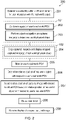
- Figure 2 schematically illustrates a flow chart of a method 200 according to an example of the present invention.
- the flowchart of Figure 2 represents one possible scenario among others.
- a user uses a head mountable display to view a virtual reality environment (e.g. virtual world 602' of Figure 6B ).
- a determination is made as to whether or not there is an availability/opportunity within the virtual reality environment for user interaction with the real world object.
- the real world object is a user input device, namely a physical keyboard, for providing text input (such as command or communication) into the virtual reality environment, a determination is made as to whether or not there is an appropriate opportunity for text input via the physical keyboard. In certain particular examples, such as shown in Figures 6A to 8B , this may correspond to a pop up chat box 605' or other opportunity for text input. Responsive to block 201's determination of an availability for user interaction with the real world object, this then triggers the procedure for detecting the real world object in the user's real world point of view as per block 101.
- the detection of a real world object i.e., a physical keyboard
- This detection comprises, in block 202 the capturing of one or more images of at least a part of the user's real world point of view.
- This may be achieved for example via the head mountable display comprising one or more image capturing devices that are appropriately positioned and aligned on the head mountable display such that they capture one or more 1 st person perspective images corresponding to an object scene of the user's real world point of view, i.e. in effect, capture one or more images of the real world scene that the user would see were the user not wearing the head mountable display.
- an object/image recognition process is performed on the one or more images captured in block 202 in order to identify and detect the real world object, i.e., the real world object/physical keyboard for which the determination step 201 determined there is an availability to interact with (i.e., determining an availability for text input via the physical keyboard).
- the real world object to be detected via the object/image recognition may correspond to one or more predetermined physical objects, for example user input devices such as keypads, game controllers, and other hand operated input devices including touch sensitive input devices and touch sensitive displays.
- one or more images of the detected real world object is caused to be displayed on the head mountable display in block 102.
- this may involve cropping the captured image(s) of the user's entire real world point of view such that the cropped image(s) consists substantially just of the detected real world object.
- the cropped image(s) (e.g. 601' of Figure 7B ) may then be displayed on a display of the head mountable display simultaneously with a display of the virtual reality environment (602a').
- a mixing of virtual reality and real world images is provided in which captured image(s) of the real world object are integrated into a display of a virtual environment.
- the user's point of view is monitored and tracked. This may be achieved by one or more orientation or directional sensors mountable in the head mountable display that can monitor and detect changes in the orientation and direction of the head mountable display and thus determining the real world point of view of the user wearing the head mountable display based on a sensed direction and orientation (e.g. yaw, pitch and roll) of the user's head.
- a sensed direction and orientation e.g. yaw, pitch and roll
- the user's point of view may be determined based on a direction and orientation of the user's eyes.
- one or more devices for sensing an orientation and direction of view of a user's eyes may be provided in the head mountable display, such as internally mounted camera's facing towards the user's eyes tracking the user's eye movement.
- a relative position of the real world object with respect to the user's real world point of view is determined. This may be achieved, for example, based on an analysis of the image(s) captured from the user's real world point of view and determining the position of the detected real world object in the captured image(s).
- this determined relative position of the real world object with respect to the user's real world point of view is used to adjust the relative position of the displayed captured image(s) of the real world object within the display of the head mountable display.
- an advantage of some examples of the present disclosure may be to enable the captured image(s) to be displayed at a virtual position in the display of the head mountable display which corresponds to a real world position of the object with respect to the user's real world point of view.
- a user input may be detected, such as a predetermined gesture captured and recognised by the image capturing device of the head mountable display, which causes, in block 209, the removal of the display of the captured image(s).
- a user may selectively control the removal of the display of the captured image(s) where the user no longer desires/requires its display. For example, the user may have completed his or her interaction with the real world object and/or does not desire to interact with the real world object and thus does not need to be presented with a captured image(s) of the same.
- the above described method discusses the capturing of one or more images of a user's real world point of view and displaying one or more images in a display of a head mountable display based on the captured images.
- the captured at least one image may correspond to any of: a sequence of images, a video, real time images.
- the at least one captured image which is displayed may also correspond to a live camera feed of a region where the object is detected.
- an advantage of some examples of the present disclosure may be to enable a user to see for his or herself, his or her own user interaction with the real world object in real time thereby facilitating the user's interaction with the real world object whilst still wearing the head mountable display and viewing the virtual reality environment (e.g. seeing a display of the user's own hands 606'over the keyboard 601' as shown in Figure 7B ).
- the present invention takes the form of a method, an apparatus or a computer program. Accordingly, examples may be implemented in hardware, software or a combination of hardware and software.
- FIG. 1 and 2 represent actions in a method and/or sections of instructions/code in a computer program. It will be understood that each block and combinations of blocks is implemented by hardware, firmware, and/or software including one or more computer program instructions. For example, one or more of the procedures described above may be embodied by computer program instructions. In this regard, the computer program instructions which embody the procedures described above may be stored by a memory storage device and performed by a processor.
- any such computer program instructions may be loaded onto a computer or other programmable apparatus (i.e., hardware) to produce a machine, such that the instructions when performed on the programmable apparatus create means for implementing the functions specified in the blocks.
- These computer program instructions may also be stored in a computer-readable medium that can direct a programmable apparatus to function in a particular manner, such that the instructions stored in the computer-readable memory produce an article of manufacture including instruction means which implement the function specified in the blocks.
- the computer program instructions may also be loaded onto a programmable apparatus to cause a series of operational actions to be performed on the programmable apparatus to produce a computer-implemented process such that the instructions which are performed on the programmable apparatus provide actions for implementing the functions specified in the blocks.
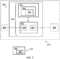
- FIG. 3 focuses on the functional components necessary for describing the operation of the apparatus.
- the apparatus 300 comprises a controller 301.
- Implementation of the controller 301 can be in hardware alone (e.g. processing circuitry comprising one or more processors and memory circuitry comprising one or more memory elements), have certain aspects in software including firmware alone or can be a combination of hardware and software (including firmware).
- the controller 301 may be implemented using instructions that enable hardware functionality, for example, by using executable computer program instructions in a general-purpose or special-purpose processor that may be stored on a computer readable storage medium (disk, memory etc) or carried by a signal carrier to be performed by such a processor.
- a general-purpose or special-purpose processor may be stored on a computer readable storage medium (disk, memory etc) or carried by a signal carrier to be performed by such a processor.
- the apparatus 300 comprises a controller 301 which is provided by a processor 302 and memory 303.
- a single processor and a single memory are illustrated in other implementations there may be multiple processors and/or there may be multiple memories some or all of which may be integrated/removable and/or may provide permanent/semi-permanent/ dynamic/cached storage.
- the memory 303 stores a computer program 304 comprising computer program instructions 305 that control the operation of the apparatus when loaded into the processor 302.
- the computer program instructions provide the logic and routines that enable the apparatus to perform the methods presently described.
- the at least one memory 303 and the computer program instructions 305 are configured to, with the at least one processor 302, cause the apparatus 300 at least to perform the method described, for example with respect to Figures 1 and 2 .
- the processor 302 is configured to read from and write to the memory 303.
- the processor 302 may also comprise an input interface 306 via which data (not least for example image capture data for detecting and displaying an image of the real world object, sensor data to determine the user's point of view, virtual reality environment data for displaying a virtual reality environment and user input data) and/or commands are input to the processor 302.
- the processor 302 may also comprise an output interface 307 via which data (not least for example captured image data of the real world object, and virtual reality environment data for displaying on the head mountable display) and/or commands are output by the processor 302.
- the computer program may arrive at the apparatus 300 via any suitable delivery mechanism 311.
- the delivery mechanism 311 may be, for example, a non-transitory computer-readable storage medium, a computer program product, a memory device, a record medium such as a compact disc read-only memory or digital versatile disc, or an article of manufacture that tangibly embodies the computer program 304.
- the delivery mechanism may be a signal configured to reliably transfer the computer program 304.
- the apparatus 300 may receive, propagate or transmit the computer program 304 as a computer data signal.
- references to 'computer-readable storage medium', 'computer program product', 'tangibly embodied computer program' etc. or a 'controller', 'computer', 'processor' etc. should be understood to encompass not only computers having different architectures such as single /multi- processor architectures and sequential (Von Neumann)/parallel architectures but also specialized circuits such as field-programmable gate arrays (FPGA), application specific circuits (ASIC), signal processing devices and other devices.
- References to computer program, instructions, code etc. should be understood to encompass software for a programmable processor or firmware such as, for example, the programmable content of a hardware device whether instructions for a processor, or configuration settings for a fixed-function device, gate array or programmable logic device etc.
- the apparatus may, for example, be: circuitry, a chipset, module or a device/system 310 which additionally comprises additional devices/components for example one or more: image capturing devices 308, display devices 309, and sensors (not shown) for detecting and monitoring a user's real world point of view.
- the apparatus may be comprised in the head mountable display or may be separate from the head mountable display and in communication (direct or otherwise) therewith, for example via a wired or wireless communication.
- the apparatus may be for displaying, on a head mountable display, at least one captured image of at least a part of the real world object detected within a real world point of view of a user of the head mountable display.
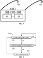
- FIG. 4 schematically illustrates a further apparatus 410 according to an example of the present disclosure.
- the apparatus 410 is in the form of a head mountable display providing a near eye display device, in particular in the form of glasses/goggles to be worn by a user.
- the head mountable display may provide an opaque/non-transparent/non-see through wearable display.
- the device 410 comprises the apparatus 300 Figure 3 and additionally two display devices 409 to provide stereoscopic display to the user and two image capturing devices 408 and 408 to enable stereoscopic image capturing of the user's real world point of view.
- the device may comprise one or more sensors 408' to detect and monitor a user's real world point of view (e.g. sensors for measuring direction/orientation).
- the device may also comprise one or more audio output devices 409'.
- the device may additionally comprise a communication interface (not shown) for communicating with remote computing devices, e.g. a data source which provides the data for a virtual reality environment displayed on the device.
- the apparatus 300/410 may additionally provide one or more audio/text/video communication functions (e.g. tele-communication, video-communication, and/or text transmission (Short Message Service (SMS)/ Multimedia Message Service (MMS)/emailing) functions), interactive/non-interactive viewing functions (e.g. web-browsing, navigation, TV/program viewing functions), music recording/playing functions (e.g. Moving Picture Experts Group-1 Audio Layer 3 (MP3) or other format and/or (frequency modulation/amplitude modulation) radio broadcast recording/playing), downloading/sending of data functions, image capture function (e.g. using a (e.g. in-built) digital camera), and gaming functions.
- audio/text/video communication functions e.g. tele-communication, video-communication, and/or text transmission (Short Message Service (SMS)/ Multimedia Message Service (MMS)/emailing) functions
- interactive/non-interactive viewing functions e.g. web-browsing, navigation, TV/
- each of the components described below may be one or more of any device, means or circuitry embodied in hardware, software or a combination of hardware and software that is configured to perform the corresponding functions of the respective components as described in greater detail below.
- circuitry refers to all of the following:
- circuitry would also cover an implementation of merely a processor (or multiple processors) or portion of a processor and its (or their) accompanying software and/or firmware.
- circuitry would also cover, for example and if applicable to the particular claim element, a baseband integrated circuit or applications processor integrated circuit for a mobile phone or a similar integrated circuit in a server, a cellular network device, or other network device.”
- Examples of the present disclosure provide both a method and corresponding apparatus consisting of various modules or means that provide the functionality for performing the actions of the method.
- the modules or means may be implemented as hardware, or may be implemented as software or firmware to be performed by a computer processor.
- examples of the present disclosure can be provided as a computer program product including a computer readable storage structure embodying computer program instructions (i.e. the software or firmware) thereon for performing by the computer processor.
- the apparatus may be provided in a module.
- module refers to a unit or apparatus that excludes certain parts/components that would be added by an end manufacturer or a user.
- the apparatus could be provided as a module to be used in conjunction with a head mountable display.
- the apparatus may be provided in the head mountable display itself, other types of electronic devices, such as, but not limited to, hand portable electronic devices, tablets, mobile phones, personal digital assistants (PDAs), pagers, mobile computers, desktop computers, televisions, gaming devices, laptop computers, cameras, video recorders and other types of electronic systems, may be provided with apparatuses in accordance with examples of the present disclosure.
- PDAs personal digital assistants
- Such other devices and types of systems being configured to communicate with and control the display of a head mountable device.
- Figure 5 shows a flow chart 500 of a particular example, in accordance with the present invention, relating to the input of text entry via a keyboard in a virtual reality environment/world.
- FIGs 6A to 8B it is determined whether or not a user is able to input anything using a keyboard. Since showing the user's keyboard in the virtual environment/world view takes up screen space, it is desirable to show the keyboard only when necessary. If there is no possibility of inputting anything, the sequential parts of the process are not carried out and the keyboard will not be shown. If there is no possibility to enter text the system waits until there is a possibility to enter text before continuing on with the procedure.
- the possibility to enter text may correspond to a chat window comment box 605' being present/displayed in the virtual environment 602'. This may indicate that keyboard input is possible. If there is a possibility to enter text the flow chart continues to block 502.
- the system waits until such time that the keyboard is in the camera feed and/or there is a possibility to enter text.
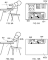
- the user's real world point of view 602 is such that the keyboard 601 is not located within the user's real world point of view 602. Accordingly, no image of the keyboard is captured and displayed on the head mountable display, as shown in Figures 6B and 8B in which there is only the display of the virtual world environment 602'.
- the virtual world environment 602a' displayed has a virtual point of view 602a' corresponding to the user's real world point of view 602a, for example, were the user to turn his/her head to the left, right or upwards, the perspective of the virtual environment displayed would adjust so as to represent a corresponding virtual perspective/viewpoint looking towards the left, right or upwards.
- the flow chart proceeds to block 503 in which the camera feed is displayed to the user.
- a video window may be displayed in the head mountable display which shows at least a part of the camera's view.
- object recognition methods are performed on the captured images. The user may perform an initial set up to teach the object recognition system what his or her keyboard looks like so as to improve object recognition and the tracking of the keyboard.
- Figure 7A the user has looked down, i.e.
- the keyboard may be detected and an image of the keyboard 601' can be displayed along with the virtual reality environment 602a' (which has a virtual point of view 602a' corresponding to the user's real world point of view 602a). Since a live feed of captured image of the keyboard is presented to the user in a video window overlaying the virtual reality environment, the user is able to see footage 606' of the user's hands 606 in the vicinity of the keyboard such that the user can see him or herself operate the keyboard and select the desired keys for typing.
- the camera feed may be cropped such that only the relevant part of the camera feed is displayed, namely that of the keyboard itself as opposed to the entirety of the field of view of camera feed.
- the user can input text and respond to the chat window.
- the user can once more look up, as shown in Figure 8A so that the user's field of view no longer includes the keyboard and the image of the keyboard is no longer displayed as shown in Figure 8B .
- the user's real world point of view 602a is such that the keyboard 601 is located at a bottom portion of the user's real world point of view 602a.
- the captured image of the keyboard 601' is correspondingly displayed such that it is at a bottom of the virtual field of view of the user's virtual environment 602a'.
- the user's real world point of view 602b is such that the keyboard 601 is located at a top portion of user's real world point of view 602b and correspondingly the captured image of the keyboard 601' is displayed at a top portion of the user's virtual point of view of the virtual environment 602b'.
- the displayed keyboard image 601' is shown at a position relative to the virtual point of view 602b' corresponding to a position of the actual keyboard relative to the user's real world point of view 602b. This facilitates the user interaction with the keyboard as the image of the keyboard is perceived to be in its appropriate position relative to its true position in real life.
- Figure 11A shows a screenshot of a display of the head mountable display wherein a user looking down on the keyboard is presented with a display of the captured image of the keyboard 601' along with a representation of the virtual world environment 602' having a particular virtual field of view.
- the user can perform a gesture with his or her hands 112, for example turning both of his hands palm up and moving them away from each other out of view of the camera.
- Such a predetermined user input or gesture can be detected and interpreted as a control signal to remove the display of the keyboard 601' following which the image of the keyboard is removed as shown in Figure 11B .
- the user's hands may be tracked using object recognition technology to determine the gestures.
- Figures 12 and 12B show examples of screenshots of the head mountable display in which the virtual world environment 702a' may be stretched/compressed, morphed or otherwise transformed so as to accommodate the inclusion of the display of a captured image of the keyboard 601' whilst minimising the degree to which the virtual world environment is obscured by the display of the keyboard.
- the image of the keyboard 601' is simply overlaid on top of a background image of the virtual world environment 702a'.
- the image of the keyboard obscures certain aspects of the virtual world environment, for instance the lower level windows of the three houses.
- the virtual world environment which is presented is transformed (e.g.
- the method may comprise determining whether or not there are any areas/points of interest in the virtual world environment (e.g.
- the virtual reality environment may be appropriately transformed so as to maximise the visibility of the virtual world environment and in particular, the areas/points of interest in the virtual world environment.
- the blocks support: combinations of means for performing the specified functions; combinations of actions for performing the specified functions; and computer program instructions/algorithm for performing the specified functions. It will also be understood that each block, and combinations of blocks, can be implemented by special purpose hardware-based systems which perform the specified functions or steps, or combinations of special purpose hardware and computer program instructions.
- the apparatus described may alternatively or in addition comprise apparatus which in some other examples comprises a distributed system of apparatus, for example, a client/server apparatus system.
- each apparatus forming a component and/or part of the system provides (or implements) one or more features which may collectively implement an embodiment of the present disclosure.
- an apparatus is re-configured by an entity other than its initial manufacturer to implement an embodiment of the present disclosure by being provided with additional software, for example by a user downloading such software, which when executed causes the apparatus to implement an example of an embodiment of the present disclosure (such implementation being either entirely by the apparatus or as part of a system of apparatus as mentioned hereinabove).
Landscapes
- Engineering & Computer Science (AREA)
- General Engineering & Computer Science (AREA)
- Theoretical Computer Science (AREA)
- Physics & Mathematics (AREA)
- General Physics & Mathematics (AREA)
- Human Computer Interaction (AREA)
- Computer Graphics (AREA)
- Computer Hardware Design (AREA)
- Software Systems (AREA)
- User Interface Of Digital Computer (AREA)
- Processing Or Creating Images (AREA)
- Image Analysis (AREA)
Claims (13)
- Procédé (100) mis en œuvre par du matériel, un microprogramme et/ou un logiciel comprenant :la provocation de l'affichage d'un environnement de réalité virtuelle (602') sur un dispositif d'affichage à montage sur tête (610) ;la détermination (201) de la disponibilité d'une entrée de texte via un objet du monde réel (601) à l'intérieur de l'environnement de réalité virtuelle, dans lequel l'objet du monde réel est un clavier physique ;le déclenchement (202), en réponse à la détermination de la disponibilité d'une entrée de texte, d'une capture d'au moins une image (601') d'un point de vue du monde réel (602, 602a) d'un utilisateur (603) du dispositif d'affichage à montage sur tête, dans lequel le point de vue du monde réel de l'utilisateur du dispositif d'affichage à montage sur tête correspond à un point de vue de l'utilisateur si l'utilisateur ne portait pas le dispositif d'affichage à montage sur tête ;la réalisation (203) d'une reconnaissance d'objet sur l'au moins une image (601') capturée du point de vue du monde réel de l'utilisateur pour détecter (101) si l'objet du monde réel (601) est situé dans le point de vue du monde réel (602, 602a) de l'utilisateur (603) du dispositif d'affichage à montage sur tête ; etle déclenchement, en réponse à la détection du fait que l'objet du monde réel (601) est situé dans le point de vue du monde réel (602, 602a) de l'utilisateur (603) du dispositif d'affichage à montage sur tête, d'une génération d'un affichage sur le dispositif d'affichage à montage sur tête d'au moins une image (601') capturée d'au moins une partie de l'objet du monde réel détecté.
- Procédé de la revendication 1, dans lequel l'au moins une image (601') capturée d'au moins une partie de l'objet du monde réel (601) détecté comprend un ou plusieurs parmi :
une séquence d'images capturées, une vidéo capturée, des images capturées en temps réel et un flux de caméra en direct. - Procédé de l'une quelconque des revendications précédentes, comprenant en outre la surveillance du point de vue du monde réel (602, 602a) de l'utilisateur.
- Procédé de la revendication 3, comprenant en outre le positionnement de l'affichage de l'au moins une image (601') capturée sur le dispositif d'affichage à montage sur tête (610) en fonction du point de vue du monde réel (602, 602a) surveillé de l'utilisateur.
- Procédé de l'une quelconque des revendications précédentes, dans lequel l'au moins une image (601') affichée capturée comprend une zone d'image dont la majeure partie est couverte par une représentation de l'objet du monde réel (601).
- Procédé de l'une quelconque des revendications précédentes, comprenant en outre la détermination d'un ou plusieurs points d'intérêt dans l'environnement de réalité virtuelle affiché ; et
la transformation de l'environnement de réalité virtuelle affiché de manière à maximiser la visibilité de l'environnement de réalité virtuelle et des un ou plusieurs points d'intérêt. - Procédé de l'une quelconque des revendications précédentes, comprenant en outre la suppression de l'affichage de l'au moins une image (601') capturée d'au moins une partie de l'objet du monde réel (601) détecté en réponse à la détection d'une entrée d'utilisateur.
- Procédé de l'une quelconque des revendications précédentes, dans lequel ladite détermination d'une disponibilité d'une entrée de texte comprend la détermination d'un affichage d'une fenêtre de discussion dans l'environnement de réalité virtuelle.
- Appareil (300) comprenant des moyens (301, 302, 303) configurés pour :provoquer l'affichage d'un environnement de réalité virtuelle (602') sur un dispositif d'affichage à montage sur tête (610) ;déterminer (201) la disponibilité d'une entrée de texte via un objet du monde réel (601) à l'intérieur de l'environnement de réalité virtuelle, dans lequel l'objet du monde réel est un clavier physique ;déclencher (202), en réponse à la détermination de la disponibilité d'une entrée de texte, une capture d'au moins une image (601') d'un point de vue du monde réel (602, 602a) d'un utilisateur (603) du dispositif d'affichage à montage sur tête, dans lequel le point de vue du monde réel de l'utilisateur du dispositif d'affichage à montage sur tête correspond à un point de vue de l'utilisateur si l'utilisateur ne portait pas le dispositif d'affichage à montage sur tête ;réaliser (203) une reconnaissance d'objet sur l'au moins une image (601') capturée du point de vue du monde réel de l'utilisateur pour détecter (101) si l'objet du monde réel (601) est situé dans le point de vue du monde réel (602, 602a) de l'utilisateur (603) du dispositif d'affichage à montage sur tête ; etdéclencher, en réponse à la détection du fait que l'objet du monde réel (601) est situé dans le point de vue du monde réel (602, 602a) de l'utilisateur (603) du dispositif d'affichage à montage sur tête, une génération d'un affichage sur le dispositif d'affichage à montage sur tête d'au moins une image (601') capturée d'au moins une partie de l'objet du monde réel détecté.
- Appareil (300) de la revendication 9, comprenant en outre des moyens (301, 302, 303) configurés pour permettre à l'appareil de réaliser :
le procédé selon l'une quelconque des revendications 2 à 8. - Appareil (300) de la revendication 9 ou 10 dans lequel l'appareil est un jeu de puces.
- Appareil (300) de la revendication 9 ou 10 dans lequel l'appareil est compris dans le dispositif d'affichage à montage sur tête.
- Programme informatique (304) qui, lorsqu'il est réalisé par au moins un processeur (302), provoque la réalisation du procédé selon l'une quelconque des revendications 1 à 8.
Priority Applications (7)
| Application Number | Priority Date | Filing Date | Title |
|---|---|---|---|
| EP14184455.5A EP2996017B1 (fr) | 2014-09-11 | 2014-09-11 | Procédé, appareil et programme informatique permettant d'afficher une image d'un clavier physique sur un dispositif d'affichage montable sur la tête |
| PCT/FI2015/050595 WO2016038253A1 (fr) | 2014-09-11 | 2015-09-11 | Procédé, appareil et programme informatique d'affichage d'image |
| MX2017003204A MX2017003204A (es) | 2014-09-11 | 2015-09-11 | Medoto, aparato y programa informatico para visualizar una imagen. |
| JP2017513647A JP6826029B2 (ja) | 2014-09-11 | 2015-09-11 | 画像を表示するための方法、装置およびコンピュータ・プログラム |
| US15/509,034 US10916057B2 (en) | 2014-09-11 | 2015-09-11 | Method, apparatus and computer program for displaying an image of a real world object in a virtual reality enviroment |
| CN201580048858.8A CN106716302B (zh) | 2014-09-11 | 2015-09-11 | 用于显示图像的方法、设备和计算机可读介质 |
| ZA2017/02365A ZA201702365B (en) | 2014-09-11 | 2017-04-04 | Method, apparatus and computer program for displaying an image |
Applications Claiming Priority (1)
| Application Number | Priority Date | Filing Date | Title |
|---|---|---|---|
| EP14184455.5A EP2996017B1 (fr) | 2014-09-11 | 2014-09-11 | Procédé, appareil et programme informatique permettant d'afficher une image d'un clavier physique sur un dispositif d'affichage montable sur la tête |
Publications (2)
| Publication Number | Publication Date |
|---|---|
| EP2996017A1 EP2996017A1 (fr) | 2016-03-16 |
| EP2996017B1 true EP2996017B1 (fr) | 2022-05-11 |
Family
ID=51542183
Family Applications (1)
| Application Number | Title | Priority Date | Filing Date |
|---|---|---|---|
| EP14184455.5A Active EP2996017B1 (fr) | 2014-09-11 | 2014-09-11 | Procédé, appareil et programme informatique permettant d'afficher une image d'un clavier physique sur un dispositif d'affichage montable sur la tête |
Country Status (7)
| Country | Link |
|---|---|
| US (1) | US10916057B2 (fr) |
| EP (1) | EP2996017B1 (fr) |
| JP (1) | JP6826029B2 (fr) |
| CN (1) | CN106716302B (fr) |
| MX (1) | MX2017003204A (fr) |
| WO (1) | WO2016038253A1 (fr) |
| ZA (1) | ZA201702365B (fr) |
Families Citing this family (47)
| Publication number | Priority date | Publication date | Assignee | Title |
|---|---|---|---|---|
| JP6641763B2 (ja) * | 2015-08-03 | 2020-02-05 | セイコーエプソン株式会社 | 表示システム |
| US10665019B2 (en) * | 2016-03-24 | 2020-05-26 | Qualcomm Incorporated | Spatial relationships for integration of visual images of physical environment into virtual reality |
| EP3299931A1 (fr) * | 2016-09-27 | 2018-03-28 | Alcatel Lucent | Procédé de commande de réalité transformée et système de commande de réalité transformée |
| US10168798B2 (en) * | 2016-09-29 | 2019-01-01 | Tower Spring Global Limited | Head mounted display |
| EP3327544B1 (fr) | 2016-11-25 | 2021-06-23 | Nokia Technologies Oy | Appareil, procédé associé et support lisible par ordinateur associé |
| US10839520B2 (en) * | 2017-03-03 | 2020-11-17 | The United States Of America, As Represented By The Secretary, Department Of Health & Human Services | Eye tracking applications in computer aided diagnosis and image processing in radiology |
| US10525324B2 (en) | 2017-03-07 | 2020-01-07 | vSports, LLC | Mixed-reality kick tracking and simulation |
| WO2018165278A1 (fr) | 2017-03-07 | 2018-09-13 | vGolf, LLC | Système de simulation et d'entraînement de golf en réalité mixte |
| US10409363B1 (en) | 2017-03-07 | 2019-09-10 | vGolf, LLC | Mixed-reality golf tracking and simulation |
| US10661149B2 (en) | 2017-03-07 | 2020-05-26 | vSports, LLC | Mixed-reality sports tracking and simulation |
| WO2018165284A1 (fr) | 2017-03-07 | 2018-09-13 | vSports, LLC | Système de simulation et d'entraînement sportifs à réalité mixte |
| GB2555501B (en) * | 2017-05-04 | 2019-08-28 | Sony Interactive Entertainment Europe Ltd | Head mounted display and method |
| CN109844694B (zh) * | 2017-06-15 | 2020-08-25 | 腾讯科技(深圳)有限公司 | 使用集线器连接两个不同环境的系统和方法 |
| WO2018227502A1 (fr) | 2017-06-15 | 2018-12-20 | Tencent Technology (Shenzhen) Company Limited | Système et procédé de prévisualisation instantanée de contenu immersif |
| WO2019017976A1 (fr) | 2017-07-21 | 2019-01-24 | Hewlett-Packard Development Company, L.P. | Dispositif d'entrée physique en réalité virtuelle |
| WO2019067482A1 (fr) * | 2017-09-29 | 2019-04-04 | Zermatt Technologies Llc | Affichage d'applications dans un contexte d'environnement de réalité simulée |
| JP7087364B2 (ja) * | 2017-12-04 | 2022-06-21 | 富士フイルムビジネスイノベーション株式会社 | 情報処理装置、情報処理システムおよびプログラム |
| EP3495771A1 (fr) * | 2017-12-11 | 2019-06-12 | Hexagon Technology Center GmbH | Relevé automatisé d'objets du monde réel |
| US10991138B2 (en) * | 2017-12-22 | 2021-04-27 | The Boeing Company | Systems and methods for in-flight virtual reality displays for passenger and crew assistance |
| CN112292876B (zh) * | 2018-04-20 | 2023-11-07 | 上海诺基亚贝尔股份有限公司 | 用于促进对天线的调谐的装置、方法和计算机程序 |
| US10984600B2 (en) | 2018-05-25 | 2021-04-20 | Tiff's Treats Holdings, Inc. | Apparatus, method, and system for presentation of multimedia content including augmented reality content |
| US10818093B2 (en) | 2018-05-25 | 2020-10-27 | Tiff's Treats Holdings, Inc. | Apparatus, method, and system for presentation of multimedia content including augmented reality content |
| US10600246B2 (en) | 2018-06-15 | 2020-03-24 | Microsoft Technology Licensing, Llc | Pinning virtual reality passthrough regions to real-world locations |
| US20190385372A1 (en) * | 2018-06-15 | 2019-12-19 | Microsoft Technology Licensing, Llc | Positioning a virtual reality passthrough region at a known distance |
| US11366514B2 (en) * | 2018-09-28 | 2022-06-21 | Apple Inc. | Application placement based on head position |
| US10769754B2 (en) * | 2018-10-31 | 2020-09-08 | Dolby Laboratories Licensing Corporation | Virtual reality cinema-immersive movie watching for headmounted displays |
| US10824244B2 (en) * | 2018-11-19 | 2020-11-03 | Facebook Technologies, Llc | Systems and methods for transitioning between modes of tracking real-world objects for artificial reality interfaces |
| JP7238456B2 (ja) * | 2019-02-21 | 2023-03-14 | セイコーエプソン株式会社 | 表示システム、情報処理装置の制御プログラム、及び情報処理装置の制御方法 |
| US11265487B2 (en) * | 2019-06-05 | 2022-03-01 | Mediatek Inc. | Camera view synthesis on head-mounted display for virtual reality and augmented reality |
| US11422669B1 (en) | 2019-06-07 | 2022-08-23 | Facebook Technologies, Llc | Detecting input using a stylus in artificial reality systems based on a stylus movement after a stylus selection action |
| US11334212B2 (en) * | 2019-06-07 | 2022-05-17 | Facebook Technologies, Llc | Detecting input in artificial reality systems based on a pinch and pull gesture |
| JP7242448B2 (ja) * | 2019-07-03 | 2023-03-20 | エヌ・ティ・ティ・コミュニケーションズ株式会社 | 仮想現実制御装置、仮想現実制御方法およびプログラム |
| CN114222942A (zh) * | 2019-08-12 | 2022-03-22 | 奇跃公司 | 用于虚拟和增强现实的系统和方法 |
| EP4270159A3 (fr) | 2019-09-26 | 2024-01-03 | Apple Inc. | Dispositif électronique portable présentant un environnement de réalité générée par ordinateur |
| WO2021062278A1 (fr) | 2019-09-27 | 2021-04-01 | Apple Inc. | Environnement pour communication à distance |
| JP7485527B2 (ja) | 2020-03-19 | 2024-05-16 | Lineヤフー株式会社 | 提供装置、提供方法及び提供プログラム |
| CN112462937B (zh) * | 2020-11-23 | 2022-11-08 | 青岛小鸟看看科技有限公司 | 虚拟现实设备的局部透视方法、装置及虚拟现实设备 |
| EP4295314A1 (fr) | 2021-02-08 | 2023-12-27 | Sightful Computers Ltd | Partage de contenu en réalité étendue |
| EP4288856A1 (fr) | 2021-02-08 | 2023-12-13 | Sightful Computers Ltd | Réalité étendue pour la productivité |
| EP4288950A1 (fr) | 2021-02-08 | 2023-12-13 | Sightful Computers Ltd | Interactions d'utilisateur dans une réalité étendue |
| WO2023009580A2 (fr) | 2021-07-28 | 2023-02-02 | Multinarity Ltd | Utilisation d'un appareil de réalité étendue pour la productivité |
| US11783449B2 (en) * | 2021-12-09 | 2023-10-10 | Htc Corporation | Method for adjusting displayed content based on host posture, host, and computer readable storage medium |
| WO2023130435A1 (fr) * | 2022-01-10 | 2023-07-13 | 深圳市闪至科技有限公司 | Procédé d'interaction, dispositif de visiocasque, système, et support de stockage |
| US20230334795A1 (en) | 2022-01-25 | 2023-10-19 | Multinarity Ltd | Dual mode presentation of user interface elements |
| US11948263B1 (en) | 2023-03-14 | 2024-04-02 | Sightful Computers Ltd | Recording the complete physical and extended reality environments of a user |
| US12073054B2 (en) | 2022-09-30 | 2024-08-27 | Sightful Computers Ltd | Managing virtual collisions between moving virtual objects |
| CN117827013B (zh) * | 2024-03-05 | 2024-05-14 | 青岛三诚众合智能设备科技有限公司 | 基于图像处理的生产技能智能学习方法及系统、电子设备 |
Citations (2)
| Publication number | Priority date | Publication date | Assignee | Title |
|---|---|---|---|---|
| US20060033724A1 (en) * | 2004-07-30 | 2006-02-16 | Apple Computer, Inc. | Virtual input device placement on a touch screen user interface |
| US20130325438A1 (en) * | 2012-05-31 | 2013-12-05 | Research In Motion Limited | Touchscreen Keyboard with Corrective Word Prediction |
Family Cites Families (23)
| Publication number | Priority date | Publication date | Assignee | Title |
|---|---|---|---|---|
| US9595169B2 (en) * | 2006-08-31 | 2017-03-14 | Cfph, Llc | Game of chance systems and methods |
| JP2008077572A (ja) * | 2006-09-25 | 2008-04-03 | Toshiba Corp | 画像表示装置 |
| JP2010533006A (ja) | 2007-03-01 | 2010-10-21 | ソニー コンピュータ エンタテインメント アメリカ リミテッド ライアビリテイ カンパニー | 仮想世界とコミュニケーションを取るためのシステムおよび方法 |
| JP2009025918A (ja) | 2007-07-17 | 2009-02-05 | Canon Inc | 画像処理装置、画像処理方法 |
| US8675025B2 (en) | 2009-12-17 | 2014-03-18 | Nokia Corporation | Method and apparatus for providing control over a device display based on device orientation |
| US20120113223A1 (en) * | 2010-11-05 | 2012-05-10 | Microsoft Corporation | User Interaction in Augmented Reality |
| JP5834439B2 (ja) * | 2011-03-24 | 2015-12-24 | セイコーエプソン株式会社 | 頭部装着型表示装置および頭部装着型表示装置の制御方法 |
| JP5960796B2 (ja) * | 2011-03-29 | 2016-08-02 | クアルコム,インコーポレイテッド | ローカルマルチユーザ共同作業のためのモジュール式のモバイル接続ピコプロジェクタ |
| US20120249587A1 (en) * | 2011-04-04 | 2012-10-04 | Anderson Glen J | Keyboard avatar for heads up display (hud) |
| US20130257732A1 (en) | 2012-03-29 | 2013-10-03 | Robert Duffield | Adaptive virtual keyboard |
| US9041622B2 (en) | 2012-06-12 | 2015-05-26 | Microsoft Technology Licensing, Llc | Controlling a virtual object with a real controller device |
| US9417692B2 (en) | 2012-06-29 | 2016-08-16 | Microsoft Technology Licensing, Llc | Deep augmented reality tags for mixed reality |
| US9378592B2 (en) * | 2012-09-14 | 2016-06-28 | Lg Electronics Inc. | Apparatus and method of providing user interface on head mounted display and head mounted display thereof |
| JP2014149712A (ja) * | 2013-02-01 | 2014-08-21 | Sony Corp | 情報処理装置、端末装置、情報処理方法及びプログラム |
| US9916691B2 (en) | 2013-02-14 | 2018-03-13 | Seiko Epson Corporation | Head mounted display and control method for head mounted display |
| JP2014164503A (ja) * | 2013-02-25 | 2014-09-08 | Sharp Corp | 情報端末、画像表示方法及びプログラム |
| CN105229720B (zh) * | 2013-05-21 | 2018-05-15 | 索尼公司 | 显示控制装置、显示控制方法以及记录介质 |
| US9908048B2 (en) | 2013-06-08 | 2018-03-06 | Sony Interactive Entertainment Inc. | Systems and methods for transitioning between transparent mode and non-transparent mode in a head mounted display |
| US9256072B2 (en) * | 2013-10-02 | 2016-02-09 | Philip Scott Lyren | Wearable electronic glasses that detect movement of a real object copies movement of a virtual object |
| JP2015114757A (ja) * | 2013-12-10 | 2015-06-22 | ソニー株式会社 | 情報処理装置、情報処理方法及びプログラム |
| KR102332326B1 (ko) | 2014-01-23 | 2021-11-30 | 소니그룹주식회사 | 화상 표시 장치 및 화상 표시 방법 |
| JP6355978B2 (ja) | 2014-06-09 | 2018-07-11 | 株式会社バンダイナムコエンターテインメント | プログラムおよび画像生成装置 |
| EP3179292B1 (fr) * | 2014-08-05 | 2021-03-03 | LG Electronics Inc. | Visiocasque et son procédé de commande |
-
2014
- 2014-09-11 EP EP14184455.5A patent/EP2996017B1/fr active Active
-
2015
- 2015-09-11 MX MX2017003204A patent/MX2017003204A/es unknown
- 2015-09-11 WO PCT/FI2015/050595 patent/WO2016038253A1/fr active Application Filing
- 2015-09-11 CN CN201580048858.8A patent/CN106716302B/zh active Active
- 2015-09-11 US US15/509,034 patent/US10916057B2/en active Active
- 2015-09-11 JP JP2017513647A patent/JP6826029B2/ja active Active
-
2017
- 2017-04-04 ZA ZA2017/02365A patent/ZA201702365B/en unknown
Patent Citations (2)
| Publication number | Priority date | Publication date | Assignee | Title |
|---|---|---|---|---|
| US20060033724A1 (en) * | 2004-07-30 | 2006-02-16 | Apple Computer, Inc. | Virtual input device placement on a touch screen user interface |
| US20130325438A1 (en) * | 2012-05-31 | 2013-12-05 | Research In Motion Limited | Touchscreen Keyboard with Corrective Word Prediction |
Also Published As
| Publication number | Publication date |
|---|---|
| CN106716302B (zh) | 2021-04-13 |
| ZA201702365B (en) | 2018-12-19 |
| JP2017528834A (ja) | 2017-09-28 |
| MX2017003204A (es) | 2017-07-20 |
| US10916057B2 (en) | 2021-02-09 |
| EP2996017A1 (fr) | 2016-03-16 |
| JP6826029B2 (ja) | 2021-02-03 |
| CN106716302A (zh) | 2017-05-24 |
| WO2016038253A1 (fr) | 2016-03-17 |
| US20170263056A1 (en) | 2017-09-14 |
Similar Documents
| Publication | Publication Date | Title |
|---|---|---|
| EP2996017B1 (fr) | Procédé, appareil et programme informatique permettant d'afficher une image d'un clavier physique sur un dispositif d'affichage montable sur la tête | |
| EP3997552B1 (fr) | Interface utilisateur virtuelle utilisant un périphérique dans des environnements de réalité artificielle | |
| US10585473B2 (en) | Visual gestures | |
| CN108604175B (zh) | 装置和关联方法 | |
| US11430192B2 (en) | Placement and manipulation of objects in augmented reality environment | |
| KR20230048450A (ko) | 사용자 인터페이스와 연관된 몰입을 조정 및/또는 제어하기 위한 방법 | |
| US20180143693A1 (en) | Virtual object manipulation | |
| CN108027707B (zh) | 用户终端设备、电子设备以及控制用户终端设备和电子设备的方法 | |
| US20230273674A1 (en) | Displaying physical input devices as virtual objects | |
| US20180143694A1 (en) | Mediated Reality | |
| US11209903B2 (en) | Rendering of mediated reality content | |
| WO2013167796A1 (fr) | Procédé et appareil pour modifier la présentation d'informations sur la base du niveau d'attention d'un utilisateur | |
| CN110968190B (zh) | 用于触摸检测的imu | |
| TWI653546B (zh) | 具有外置追蹤及內置追蹤之虛擬實境系統及其控制方法 | |
| WO2018090914A1 (fr) | Procédé et appareil de simulation d'effet visuel tridimensionnel, support d'informations et dispositif d'affichage | |
| CN110968248B (zh) | 生成用于视觉触摸检测的指尖的3d模型 | |
| EP3702008A1 (fr) | Affichage d'une fenêtre d'un espace virtuel | |
| US11782548B1 (en) | Speed adapted touch detection | |
| US20240248532A1 (en) | Method and device for visualizing multi-modal inputs | |
| JP6999822B2 (ja) | 端末装置および端末装置の制御方法 | |
| US20240019928A1 (en) | Gaze and Head Pose Interaction | |
| US20230333645A1 (en) | Method and device for processing user input for multiple devices | |
| US20230042447A1 (en) | Method and Device for Managing Interactions Directed to a User Interface with a Physical Object | |
| KR20240025593A (ko) | 객체에 대한 동작 양식을 동적으로 선택하기 위한 방법 및 디바이스 |
Legal Events
| Date | Code | Title | Description |
|---|---|---|---|
| PUAI | Public reference made under article 153(3) epc to a published international application that has entered the european phase |
Free format text: ORIGINAL CODE: 0009012 |
|
| AK | Designated contracting states |
Kind code of ref document: A1 Designated state(s): AL AT BE BG CH CY CZ DE DK EE ES FI FR GB GR HR HU IE IS IT LI LT LU LV MC MK MT NL NO PL PT RO RS SE SI SK SM TR |
|
| AX | Request for extension of the european patent |
Extension state: BA ME |
|
| 17P | Request for examination filed |
Effective date: 20160916 |
|
| RBV | Designated contracting states (corrected) |
Designated state(s): AL AT BE BG CH CY CZ DE DK EE ES FI FR GB GR HR HU IE IS IT LI LT LU LV MC MK MT NL NO PL PT RO RS SE SI SK SM TR |
|
| RAP1 | Party data changed (applicant data changed or rights of an application transferred) |
Owner name: NOKIA TECHNOLOGIES OY |
|
| STAA | Information on the status of an ep patent application or granted ep patent |
Free format text: STATUS: EXAMINATION IS IN PROGRESS |
|
| 17Q | First examination report despatched |
Effective date: 20191212 |
|
| STAA | Information on the status of an ep patent application or granted ep patent |
Free format text: STATUS: EXAMINATION IS IN PROGRESS |
|
| GRAP | Despatch of communication of intention to grant a patent |
Free format text: ORIGINAL CODE: EPIDOSNIGR1 |
|
| STAA | Information on the status of an ep patent application or granted ep patent |
Free format text: STATUS: GRANT OF PATENT IS INTENDED |
|
| INTG | Intention to grant announced |
Effective date: 20211210 |
|
| GRAS | Grant fee paid |
Free format text: ORIGINAL CODE: EPIDOSNIGR3 |
|
| GRAA | (expected) grant |
Free format text: ORIGINAL CODE: 0009210 |
|
| STAA | Information on the status of an ep patent application or granted ep patent |
Free format text: STATUS: THE PATENT HAS BEEN GRANTED |
|
| AK | Designated contracting states |
Kind code of ref document: B1 Designated state(s): AL AT BE BG CH CY CZ DE DK EE ES FI FR GB GR HR HU IE IS IT LI LT LU LV MC MK MT NL NO PL PT RO RS SE SI SK SM TR |
|
| REG | Reference to a national code |
Ref country code: GB Ref legal event code: FG4D |
|
| REG | Reference to a national code |
Ref country code: CH Ref legal event code: EP |
|
| REG | Reference to a national code |
Ref country code: AT Ref legal event code: REF Ref document number: 1491995 Country of ref document: AT Kind code of ref document: T Effective date: 20220515 |
|
| REG | Reference to a national code |
Ref country code: DE Ref legal event code: R096 Ref document number: 602014083668 Country of ref document: DE |
|
| REG | Reference to a national code |
Ref country code: IE Ref legal event code: FG4D |
|
| REG | Reference to a national code |
Ref country code: LT Ref legal event code: MG9D |
|
| REG | Reference to a national code |
Ref country code: NL Ref legal event code: MP Effective date: 20220511 |
|
| REG | Reference to a national code |
Ref country code: AT Ref legal event code: MK05 Ref document number: 1491995 Country of ref document: AT Kind code of ref document: T Effective date: 20220511 |
|
| PG25 | Lapsed in a contracting state [announced via postgrant information from national office to epo] |
Ref country code: SE Free format text: LAPSE BECAUSE OF FAILURE TO SUBMIT A TRANSLATION OF THE DESCRIPTION OR TO PAY THE FEE WITHIN THE PRESCRIBED TIME-LIMIT Effective date: 20220511 Ref country code: PT Free format text: LAPSE BECAUSE OF FAILURE TO SUBMIT A TRANSLATION OF THE DESCRIPTION OR TO PAY THE FEE WITHIN THE PRESCRIBED TIME-LIMIT Effective date: 20220912 Ref country code: NO Free format text: LAPSE BECAUSE OF FAILURE TO SUBMIT A TRANSLATION OF THE DESCRIPTION OR TO PAY THE FEE WITHIN THE PRESCRIBED TIME-LIMIT Effective date: 20220811 Ref country code: NL Free format text: LAPSE BECAUSE OF FAILURE TO SUBMIT A TRANSLATION OF THE DESCRIPTION OR TO PAY THE FEE WITHIN THE PRESCRIBED TIME-LIMIT Effective date: 20220511 Ref country code: LT Free format text: LAPSE BECAUSE OF FAILURE TO SUBMIT A TRANSLATION OF THE DESCRIPTION OR TO PAY THE FEE WITHIN THE PRESCRIBED TIME-LIMIT Effective date: 20220511 Ref country code: HR Free format text: LAPSE BECAUSE OF FAILURE TO SUBMIT A TRANSLATION OF THE DESCRIPTION OR TO PAY THE FEE WITHIN THE PRESCRIBED TIME-LIMIT Effective date: 20220511 Ref country code: GR Free format text: LAPSE BECAUSE OF FAILURE TO SUBMIT A TRANSLATION OF THE DESCRIPTION OR TO PAY THE FEE WITHIN THE PRESCRIBED TIME-LIMIT Effective date: 20220812 Ref country code: FI Free format text: LAPSE BECAUSE OF FAILURE TO SUBMIT A TRANSLATION OF THE DESCRIPTION OR TO PAY THE FEE WITHIN THE PRESCRIBED TIME-LIMIT Effective date: 20220511 Ref country code: ES Free format text: LAPSE BECAUSE OF FAILURE TO SUBMIT A TRANSLATION OF THE DESCRIPTION OR TO PAY THE FEE WITHIN THE PRESCRIBED TIME-LIMIT Effective date: 20220511 Ref country code: BG Free format text: LAPSE BECAUSE OF FAILURE TO SUBMIT A TRANSLATION OF THE DESCRIPTION OR TO PAY THE FEE WITHIN THE PRESCRIBED TIME-LIMIT Effective date: 20220811 Ref country code: AT Free format text: LAPSE BECAUSE OF FAILURE TO SUBMIT A TRANSLATION OF THE DESCRIPTION OR TO PAY THE FEE WITHIN THE PRESCRIBED TIME-LIMIT Effective date: 20220511 |
|
| PG25 | Lapsed in a contracting state [announced via postgrant information from national office to epo] |
Ref country code: RS Free format text: LAPSE BECAUSE OF FAILURE TO SUBMIT A TRANSLATION OF THE DESCRIPTION OR TO PAY THE FEE WITHIN THE PRESCRIBED TIME-LIMIT Effective date: 20220511 Ref country code: PL Free format text: LAPSE BECAUSE OF FAILURE TO SUBMIT A TRANSLATION OF THE DESCRIPTION OR TO PAY THE FEE WITHIN THE PRESCRIBED TIME-LIMIT Effective date: 20220511 Ref country code: LV Free format text: LAPSE BECAUSE OF FAILURE TO SUBMIT A TRANSLATION OF THE DESCRIPTION OR TO PAY THE FEE WITHIN THE PRESCRIBED TIME-LIMIT Effective date: 20220511 Ref country code: IS Free format text: LAPSE BECAUSE OF FAILURE TO SUBMIT A TRANSLATION OF THE DESCRIPTION OR TO PAY THE FEE WITHIN THE PRESCRIBED TIME-LIMIT Effective date: 20220911 |
|
| PG25 | Lapsed in a contracting state [announced via postgrant information from national office to epo] |
Ref country code: SM Free format text: LAPSE BECAUSE OF FAILURE TO SUBMIT A TRANSLATION OF THE DESCRIPTION OR TO PAY THE FEE WITHIN THE PRESCRIBED TIME-LIMIT Effective date: 20220511 Ref country code: SK Free format text: LAPSE BECAUSE OF FAILURE TO SUBMIT A TRANSLATION OF THE DESCRIPTION OR TO PAY THE FEE WITHIN THE PRESCRIBED TIME-LIMIT Effective date: 20220511 Ref country code: RO Free format text: LAPSE BECAUSE OF FAILURE TO SUBMIT A TRANSLATION OF THE DESCRIPTION OR TO PAY THE FEE WITHIN THE PRESCRIBED TIME-LIMIT Effective date: 20220511 Ref country code: EE Free format text: LAPSE BECAUSE OF FAILURE TO SUBMIT A TRANSLATION OF THE DESCRIPTION OR TO PAY THE FEE WITHIN THE PRESCRIBED TIME-LIMIT Effective date: 20220511 Ref country code: DK Free format text: LAPSE BECAUSE OF FAILURE TO SUBMIT A TRANSLATION OF THE DESCRIPTION OR TO PAY THE FEE WITHIN THE PRESCRIBED TIME-LIMIT Effective date: 20220511 Ref country code: CZ Free format text: LAPSE BECAUSE OF FAILURE TO SUBMIT A TRANSLATION OF THE DESCRIPTION OR TO PAY THE FEE WITHIN THE PRESCRIBED TIME-LIMIT Effective date: 20220511 |
|
| REG | Reference to a national code |
Ref country code: DE Ref legal event code: R097 Ref document number: 602014083668 Country of ref document: DE |
|
| PLBE | No opposition filed within time limit |
Free format text: ORIGINAL CODE: 0009261 |
|
| STAA | Information on the status of an ep patent application or granted ep patent |
Free format text: STATUS: NO OPPOSITION FILED WITHIN TIME LIMIT |
|
| PG25 | Lapsed in a contracting state [announced via postgrant information from national office to epo] |
Ref country code: AL Free format text: LAPSE BECAUSE OF FAILURE TO SUBMIT A TRANSLATION OF THE DESCRIPTION OR TO PAY THE FEE WITHIN THE PRESCRIBED TIME-LIMIT Effective date: 20220511 |
|
| 26N | No opposition filed |
Effective date: 20230214 |
|
| PG25 | Lapsed in a contracting state [announced via postgrant information from national office to epo] |
Ref country code: MC Free format text: LAPSE BECAUSE OF FAILURE TO SUBMIT A TRANSLATION OF THE DESCRIPTION OR TO PAY THE FEE WITHIN THE PRESCRIBED TIME-LIMIT Effective date: 20220511 |
|
| REG | Reference to a national code |
Ref country code: CH Ref legal event code: PL |
|
| REG | Reference to a national code |
Ref country code: BE Ref legal event code: MM Effective date: 20220930 |
|
| PG25 | Lapsed in a contracting state [announced via postgrant information from national office to epo] |
Ref country code: SI Free format text: LAPSE BECAUSE OF FAILURE TO SUBMIT A TRANSLATION OF THE DESCRIPTION OR TO PAY THE FEE WITHIN THE PRESCRIBED TIME-LIMIT Effective date: 20220511 |
|
| PG25 | Lapsed in a contracting state [announced via postgrant information from national office to epo] |
Ref country code: LU Free format text: LAPSE BECAUSE OF NON-PAYMENT OF DUE FEES Effective date: 20220911 |
|
| PG25 | Lapsed in a contracting state [announced via postgrant information from national office to epo] |
Ref country code: LI Free format text: LAPSE BECAUSE OF NON-PAYMENT OF DUE FEES Effective date: 20220930 Ref country code: IE Free format text: LAPSE BECAUSE OF NON-PAYMENT OF DUE FEES Effective date: 20220911 Ref country code: CH Free format text: LAPSE BECAUSE OF NON-PAYMENT OF DUE FEES Effective date: 20220930 |
|
| PG25 | Lapsed in a contracting state [announced via postgrant information from national office to epo] |
Ref country code: BE Free format text: LAPSE BECAUSE OF NON-PAYMENT OF DUE FEES Effective date: 20220930 |
|
| PGFP | Annual fee paid to national office [announced via postgrant information from national office to epo] |
Ref country code: GB Payment date: 20230803 Year of fee payment: 10 |
|
| PGFP | Annual fee paid to national office [announced via postgrant information from national office to epo] |
Ref country code: FR Payment date: 20230808 Year of fee payment: 10 Ref country code: DE Payment date: 20230802 Year of fee payment: 10 |
|
| PG25 | Lapsed in a contracting state [announced via postgrant information from national office to epo] |
Ref country code: IT Free format text: LAPSE BECAUSE OF FAILURE TO SUBMIT A TRANSLATION OF THE DESCRIPTION OR TO PAY THE FEE WITHIN THE PRESCRIBED TIME-LIMIT Effective date: 20220511 |
|
| PG25 | Lapsed in a contracting state [announced via postgrant information from national office to epo] |
Ref country code: HU Free format text: LAPSE BECAUSE OF FAILURE TO SUBMIT A TRANSLATION OF THE DESCRIPTION OR TO PAY THE FEE WITHIN THE PRESCRIBED TIME-LIMIT; INVALID AB INITIO Effective date: 20140911 |
|
| PG25 | Lapsed in a contracting state [announced via postgrant information from national office to epo] |
Ref country code: CY Free format text: LAPSE BECAUSE OF FAILURE TO SUBMIT A TRANSLATION OF THE DESCRIPTION OR TO PAY THE FEE WITHIN THE PRESCRIBED TIME-LIMIT Effective date: 20220511 |
|
| PG25 | Lapsed in a contracting state [announced via postgrant information from national office to epo] |
Ref country code: MK Free format text: LAPSE BECAUSE OF FAILURE TO SUBMIT A TRANSLATION OF THE DESCRIPTION OR TO PAY THE FEE WITHIN THE PRESCRIBED TIME-LIMIT Effective date: 20220511 |