EP3098426A1 - Adaptives flugzeugtriebwerk und flugzeug mit einem adaptiven triebwerk - Google Patents
Adaptives flugzeugtriebwerk und flugzeug mit einem adaptiven triebwerk Download PDFInfo
- Publication number
- EP3098426A1 EP3098426A1 EP16171829.1A EP16171829A EP3098426A1 EP 3098426 A1 EP3098426 A1 EP 3098426A1 EP 16171829 A EP16171829 A EP 16171829A EP 3098426 A1 EP3098426 A1 EP 3098426A1
- Authority
- EP
- European Patent Office
- Prior art keywords
- aircraft engine
- net
- flow
- adaptive
- aircraft
- Prior art date
- Legal status (The legal status is an assumption and is not a legal conclusion. Google has not performed a legal analysis and makes no representation as to the accuracy of the status listed.)
- Granted
Links
Images



Classifications
-
- B—PERFORMING OPERATIONS; TRANSPORTING
- B64—AIRCRAFT; AVIATION; COSMONAUTICS
- B64D—EQUIPMENT FOR FITTING IN OR TO AIRCRAFT; FLIGHT SUITS; PARACHUTES; ARRANGEMENT OR MOUNTING OF POWER PLANTS OR PROPULSION TRANSMISSIONS IN AIRCRAFT
- B64D27/00—Arrangement or mounting of power plants in aircraft; Aircraft characterised by the type or position of power plants
- B64D27/02—Aircraft characterised by the type or position of power plants
- B64D27/16—Aircraft characterised by the type or position of power plants of jet type
-
- B—PERFORMING OPERATIONS; TRANSPORTING
- B64—AIRCRAFT; AVIATION; COSMONAUTICS
- B64C—AEROPLANES; HELICOPTERS
- B64C30/00—Supersonic type aircraft
-
- F—MECHANICAL ENGINEERING; LIGHTING; HEATING; WEAPONS; BLASTING
- F01—MACHINES OR ENGINES IN GENERAL; ENGINE PLANTS IN GENERAL; STEAM ENGINES
- F01D—NON-POSITIVE DISPLACEMENT MACHINES OR ENGINES, e.g. STEAM TURBINES
- F01D15/00—Adaptations of machines or engines for special use; Combinations of engines with devices driven thereby
- F01D15/12—Combinations with mechanical gearing
-
- F—MECHANICAL ENGINEERING; LIGHTING; HEATING; WEAPONS; BLASTING
- F01—MACHINES OR ENGINES IN GENERAL; ENGINE PLANTS IN GENERAL; STEAM ENGINES
- F01D—NON-POSITIVE DISPLACEMENT MACHINES OR ENGINES, e.g. STEAM TURBINES
- F01D17/00—Regulating or controlling by varying flow
- F01D17/10—Final actuators
- F01D17/12—Final actuators arranged in stator parts
- F01D17/14—Final actuators arranged in stator parts varying effective cross-sectional area of nozzles or guide conduits
- F01D17/16—Final actuators arranged in stator parts varying effective cross-sectional area of nozzles or guide conduits by means of nozzle vanes
- F01D17/162—Final actuators arranged in stator parts varying effective cross-sectional area of nozzles or guide conduits by means of nozzle vanes for axial flow, i.e. the vanes turning around axes which are essentially perpendicular to the rotor centre line
-
- F—MECHANICAL ENGINEERING; LIGHTING; HEATING; WEAPONS; BLASTING
- F02—COMBUSTION ENGINES; HOT-GAS OR COMBUSTION-PRODUCT ENGINE PLANTS
- F02C—GAS-TURBINE PLANTS; AIR INTAKES FOR JET-PROPULSION PLANTS; CONTROLLING FUEL SUPPLY IN AIR-BREATHING JET-PROPULSION PLANTS
- F02C9/00—Controlling gas-turbine plants; Controlling fuel supply in air- breathing jet-propulsion plants
- F02C9/16—Control of working fluid flow
- F02C9/18—Control of working fluid flow by bleeding, bypassing or acting on variable working fluid interconnections between turbines or compressors or their stages
-
- F—MECHANICAL ENGINEERING; LIGHTING; HEATING; WEAPONS; BLASTING
- F02—COMBUSTION ENGINES; HOT-GAS OR COMBUSTION-PRODUCT ENGINE PLANTS
- F02C—GAS-TURBINE PLANTS; AIR INTAKES FOR JET-PROPULSION PLANTS; CONTROLLING FUEL SUPPLY IN AIR-BREATHING JET-PROPULSION PLANTS
- F02C9/00—Controlling gas-turbine plants; Controlling fuel supply in air- breathing jet-propulsion plants
- F02C9/16—Control of working fluid flow
- F02C9/20—Control of working fluid flow by throttling; by adjusting vanes
- F02C9/22—Control of working fluid flow by throttling; by adjusting vanes by adjusting turbine vanes
-
- F—MECHANICAL ENGINEERING; LIGHTING; HEATING; WEAPONS; BLASTING
- F02—COMBUSTION ENGINES; HOT-GAS OR COMBUSTION-PRODUCT ENGINE PLANTS
- F02K—JET-PROPULSION PLANTS
- F02K1/00—Plants characterised by the form or arrangement of the jet pipe or nozzle; Jet pipes or nozzles peculiar thereto
- F02K1/06—Varying effective area of jet pipe or nozzle
- F02K1/09—Varying effective area of jet pipe or nozzle by axially moving an external member, e.g. a shroud
-
- F—MECHANICAL ENGINEERING; LIGHTING; HEATING; WEAPONS; BLASTING
- F02—COMBUSTION ENGINES; HOT-GAS OR COMBUSTION-PRODUCT ENGINE PLANTS
- F02K—JET-PROPULSION PLANTS
- F02K1/00—Plants characterised by the form or arrangement of the jet pipe or nozzle; Jet pipes or nozzles peculiar thereto
- F02K1/06—Varying effective area of jet pipe or nozzle
- F02K1/15—Control or regulation
-
- F—MECHANICAL ENGINEERING; LIGHTING; HEATING; WEAPONS; BLASTING
- F02—COMBUSTION ENGINES; HOT-GAS OR COMBUSTION-PRODUCT ENGINE PLANTS
- F02K—JET-PROPULSION PLANTS
- F02K3/00—Plants including a gas turbine driving a compressor or a ducted fan
- F02K3/02—Plants including a gas turbine driving a compressor or a ducted fan in which part of the working fluid by-passes the turbine and combustion chamber
-
- F—MECHANICAL ENGINEERING; LIGHTING; HEATING; WEAPONS; BLASTING
- F02—COMBUSTION ENGINES; HOT-GAS OR COMBUSTION-PRODUCT ENGINE PLANTS
- F02K—JET-PROPULSION PLANTS
- F02K3/00—Plants including a gas turbine driving a compressor or a ducted fan
- F02K3/02—Plants including a gas turbine driving a compressor or a ducted fan in which part of the working fluid by-passes the turbine and combustion chamber
- F02K3/04—Plants including a gas turbine driving a compressor or a ducted fan in which part of the working fluid by-passes the turbine and combustion chamber the plant including ducted fans, i.e. fans with high volume, low pressure outputs, for augmenting the jet thrust, e.g. of double-flow type
- F02K3/06—Plants including a gas turbine driving a compressor or a ducted fan in which part of the working fluid by-passes the turbine and combustion chamber the plant including ducted fans, i.e. fans with high volume, low pressure outputs, for augmenting the jet thrust, e.g. of double-flow type with front fan
-
- F—MECHANICAL ENGINEERING; LIGHTING; HEATING; WEAPONS; BLASTING
- F02—COMBUSTION ENGINES; HOT-GAS OR COMBUSTION-PRODUCT ENGINE PLANTS
- F02K—JET-PROPULSION PLANTS
- F02K3/00—Plants including a gas turbine driving a compressor or a ducted fan
- F02K3/02—Plants including a gas turbine driving a compressor or a ducted fan in which part of the working fluid by-passes the turbine and combustion chamber
- F02K3/04—Plants including a gas turbine driving a compressor or a ducted fan in which part of the working fluid by-passes the turbine and combustion chamber the plant including ducted fans, i.e. fans with high volume, low pressure outputs, for augmenting the jet thrust, e.g. of double-flow type
- F02K3/075—Plants including a gas turbine driving a compressor or a ducted fan in which part of the working fluid by-passes the turbine and combustion chamber the plant including ducted fans, i.e. fans with high volume, low pressure outputs, for augmenting the jet thrust, e.g. of double-flow type controlling flow ratio between flows
-
- F—MECHANICAL ENGINEERING; LIGHTING; HEATING; WEAPONS; BLASTING
- F02—COMBUSTION ENGINES; HOT-GAS OR COMBUSTION-PRODUCT ENGINE PLANTS
- F02K—JET-PROPULSION PLANTS
- F02K3/00—Plants including a gas turbine driving a compressor or a ducted fan
- F02K3/02—Plants including a gas turbine driving a compressor or a ducted fan in which part of the working fluid by-passes the turbine and combustion chamber
- F02K3/04—Plants including a gas turbine driving a compressor or a ducted fan in which part of the working fluid by-passes the turbine and combustion chamber the plant including ducted fans, i.e. fans with high volume, low pressure outputs, for augmenting the jet thrust, e.g. of double-flow type
- F02K3/077—Plants including a gas turbine driving a compressor or a ducted fan in which part of the working fluid by-passes the turbine and combustion chamber the plant including ducted fans, i.e. fans with high volume, low pressure outputs, for augmenting the jet thrust, e.g. of double-flow type the plant being of the multiple flow type, i.e. having three or more flows
-
- F—MECHANICAL ENGINEERING; LIGHTING; HEATING; WEAPONS; BLASTING
- F05—INDEXING SCHEMES RELATING TO ENGINES OR PUMPS IN VARIOUS SUBCLASSES OF CLASSES F01-F04
- F05D—INDEXING SCHEME FOR ASPECTS RELATING TO NON-POSITIVE-DISPLACEMENT MACHINES OR ENGINES, GAS-TURBINES OR JET-PROPULSION PLANTS
- F05D2220/00—Application
- F05D2220/30—Application in turbines
- F05D2220/32—Application in turbines in gas turbines
- F05D2220/323—Application in turbines in gas turbines for aircraft propulsion, e.g. jet engines
-
- F—MECHANICAL ENGINEERING; LIGHTING; HEATING; WEAPONS; BLASTING
- F05—INDEXING SCHEMES RELATING TO ENGINES OR PUMPS IN VARIOUS SUBCLASSES OF CLASSES F01-F04
- F05D—INDEXING SCHEME FOR ASPECTS RELATING TO NON-POSITIVE-DISPLACEMENT MACHINES OR ENGINES, GAS-TURBINES OR JET-PROPULSION PLANTS
- F05D2240/00—Components
- F05D2240/10—Stators
- F05D2240/12—Fluid guiding means, e.g. vanes
- F05D2240/128—Nozzles
-
- F—MECHANICAL ENGINEERING; LIGHTING; HEATING; WEAPONS; BLASTING
- F05—INDEXING SCHEMES RELATING TO ENGINES OR PUMPS IN VARIOUS SUBCLASSES OF CLASSES F01-F04
- F05D—INDEXING SCHEME FOR ASPECTS RELATING TO NON-POSITIVE-DISPLACEMENT MACHINES OR ENGINES, GAS-TURBINES OR JET-PROPULSION PLANTS
- F05D2240/00—Components
- F05D2240/20—Rotors
- F05D2240/30—Characteristics of rotor blades, i.e. of any element transforming dynamic fluid energy to or from rotational energy and being attached to a rotor
-
- F—MECHANICAL ENGINEERING; LIGHTING; HEATING; WEAPONS; BLASTING
- F05—INDEXING SCHEMES RELATING TO ENGINES OR PUMPS IN VARIOUS SUBCLASSES OF CLASSES F01-F04
- F05D—INDEXING SCHEME FOR ASPECTS RELATING TO NON-POSITIVE-DISPLACEMENT MACHINES OR ENGINES, GAS-TURBINES OR JET-PROPULSION PLANTS
- F05D2270/00—Control
- F05D2270/01—Purpose of the control system
- F05D2270/20—Purpose of the control system to optimize the performance of a machine
-
- Y—GENERAL TAGGING OF NEW TECHNOLOGICAL DEVELOPMENTS; GENERAL TAGGING OF CROSS-SECTIONAL TECHNOLOGIES SPANNING OVER SEVERAL SECTIONS OF THE IPC; TECHNICAL SUBJECTS COVERED BY FORMER USPC CROSS-REFERENCE ART COLLECTIONS [XRACs] AND DIGESTS
- Y02—TECHNOLOGIES OR APPLICATIONS FOR MITIGATION OR ADAPTATION AGAINST CLIMATE CHANGE
- Y02T—CLIMATE CHANGE MITIGATION TECHNOLOGIES RELATED TO TRANSPORTATION
- Y02T50/00—Aeronautics or air transport
- Y02T50/60—Efficient propulsion technologies, e.g. for aircraft
Definitions
- the invention relates to an adaptive aircraft engine having the features of claim 1 and an aircraft having the features of claim 16.
- VCE Variable Cycle Engines
- the task is to create new and more efficient aircraft engines. This object is achieved by an aircraft engine having the features of claim 1.
- the aircraft engine has a first, inner bypass duct in a core engine.
- a second outer bypass channel surrounds the first Maustromkanal at least partially.
- Adaptation means in particular adaptive nozzles (ie nozzles with an adaptively adaptable cross-section) serve to change a cross-section of the core engine with the first bypass channel and the change in the cross section of the second bypass channel as a function of the airspeed.
- the proportion of the net thrust F primary, net of the primary nozzle and / or the proportion of the net thrust F secondary is adjustable net depending on the airspeed, in particular to values for F primary, net of 50% of the net thrust (F net ) in the case of take-off (maximum take-off) up to 91% of the net thrust (F net ) in the case of supersonic cruise speed and value for F secondary, net of 50% of the net thrust (F net ) in the case of take-off (maximum take-off) up to 9% of net thrust (F net ) in the case of cruise supersonic speed.
- the amount of thrust through the primary nozzle ie, the inner nozzle
- the amount of thrust through the secondary nozzle ie, the outer nozzle
- a flow-through cross section of the second, outer bypass channel in the case of supersonic flow, in particular at Ma> 1.4 can be enlarged, in particular maximized.
- the flow resistance of the outer parts of the aircraft engine can be minimized at high speeds.
- a flow-through cross-section of the second bypass channel in subsonic flow, in particular at Ma ⁇ 0.8 can be reduced, in particular minimized.
- the cross-section of the second bypass channel is increased so that at supersonic flow, the difference between the net thrust of the secondary nozzle (F secondary, effective ' ) and the installation resistance of the secondary circuit (ID secondary ) - ie the effective Thrust (F- secondary, effective) of the secondary nozzle - becomes small, especially minimal.
- an additional intake is provided in the intake area of the aircraft engine in one embodiment of the adaptive aircraft engine, this can be opened in subsonic conditions and closed at supersonic conditions.
- a fan rotor For setting the respective operating conditions, in one embodiment, a fan rotor, at least one controllable or controllable fan following wheel, at least one controllable or controllable leading wheel of a low-pressure turbine and / or at least one controllable or controllable idler wheel of a low-pressure turbine are provided. Together with the particular nozzle-adjustable cross sections can be made here in each case an adaptation to the necessary operating conditions.
- an embodiment may include a fan rotor coupled to a high power transmission and drivable via a turbine stage.
- the fan rotor may in particular have adjustable blades.
- the aircraft engine is designed such that it is afterburner-free.
- the operation of an afterburner is very loud, so that in particular a nachbrennerfits civil aircraft is operated under fewer conditions. Also, this measure reduces the emission of NOX gases.
- a bypass ratio Flow through first and second bypass duct Flow through fürstr O ⁇ mung fan rotor - Flow through first and second bypass duct of less than 4, in particular 3.8 is adjustable.
- a second bypass ratio (flow through inner bypass duct / flow through the inner part of the core engine) is adjustable between 1.2 and 0.8, in particular 1, for the inner bypass duct in the supersonic and subsonic areas.
- a control or control device is provided with which the adjustment of the adaptation means, in particular the primary and / or secondary nozzles, the at least one Fannachleitrades, the at least one Vorleitrades the low-pressure turbine and / or the at least one Nachleitrades the low-pressure turbine in dependence the speed of the aircraft engine can be operated.
- the adjustment of the adaptation means in particular the primary and / or secondary nozzles, the at least one Fannachleitrades, the at least one Vorleitrades the low-pressure turbine and / or the at least one Nachleitrades the low-pressure turbine in dependence the speed of the aircraft engine can be operated.
- the low-pressure turbine is at least partially drivable by a flow from a combustion chamber and a flow from the inner bypass duct.
- an outer nacelle and / or the core engine is formed axially symmetrical.
- the adaptive aircraft engine comprises a two-flow, three-shaft engine with two bypass ducts, in particular with a mixing device for a flow from the combustion chamber and a flow from the inner bypass duct, wherein the mixing device is arranged upstream of the low-pressure turbine in the flow direction.
- the at least one aircraft engine is arranged at the stern, in particular above a wing of the aircraft.
- the aircraft 100 is a Supersonic Businessjet SSBJ.
- the adaptive aircraft engines 101 are designed as two-circuit, three-shaft aircraft engines and arranged above the wings 102.
- the aircraft engines 101 have a length of about 7 m.
- the diameter of a nacelle 7 (outer nacelle) of the aircraft engines 101 is about 1.9 m.
- the diameter of a core engine cowling 10 is 1.4 m.
- the aircraft 100 has a hull length of 36 m and a wing span of 21 m. The entire wing area is 120 m 2 .
- the maximum takeoff weight is assumed to be 100,000 lb (45.4 t).
- the aircraft 100 illustrated has a lance-like aircraft nose which is specially designed for supersonic flight and has a flat shape in cross-section. Other embodiments of the aircraft 100 may also have other dimensions and / or shapes.
- each conical inlet central body 4 are provided which are surrounded radially by an inlet lip 1 (see also Fig. 2 ).
- the inlet can also be designed differently in other embodiments, as was the case for example with the Concorde.
- two nozzles 9, 13 are arranged, whose cross-sections can be adjusted adaptively convergent-divergent, which in connection with the Fig. 2 to 4 is shown in more detail.
- These two aircraft engines 101 each have a maximum take-off thrust of 20,000 lbf (88,964.4 N).
- the thrust at the nominal cruising speed of Ma 1.75 is 6,000 lbf (26,689.3 N).
- the thrust of cruising speed is 30% of the thrust at takeoff.
- other aircraft with other embodiments of the aircraft engines 101 may have different values for thrust and velocities.
- the aircraft 100 described herein and its aggregates are merely exemplary in nature, so that the adaptive aircraft engines 101 may be arranged on otherwise constructed or dimensioned civil or military aircraft.
- the size and / or power specifications of the aircraft engines 101 may be formed differently in other embodiments. It is also possible that more than two of the adaptive aircraft engines 101 are used on an aircraft 100.
- the adaptive aircraft engines 101 ensure that a fan engine with a relatively high bypass ratio is present during takeoff and subsonic flight (eg Ma ⁇ 0.8). This reduces starting noise and fuel consumption. In supersonic flight (eg Ma> 1.4) is ensured by suitable cross-sectional changes of the nozzles 9, 13, which cooperate with two bypass channels 8, 15, that the Flow resistance of the aircraft engines 101 is low.
- the outer nozzle 9 is located downstream of the outer bypass channel 8
- the inner nozzle 13 is located downstream of the inner bypass channel 15 and downstream of a low-pressure turbine 12th
- the low-pressure turbine 12 is arranged so that it is exposed not only to the outflowing gases from a combustion chamber of the core engine 14, but also the flow in the inner bypass channel 15, i. both flows drive the low-pressure turbine 12.
- a mixing device 16 In front of the low pressure turbine 12 is a mixing device 16 - e.g. a mixing chamber - arranged, in which the two currents can mix.
- a mixing device 16 In front of the low pressure turbine 12 is a mixing device 16 - e.g. a mixing chamber - arranged, in which the two currents can mix.
- the flow of the core engine 14 then acts on the low-pressure turbine 12.
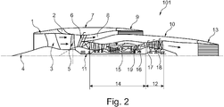
- Fig. 2 a three-shaft turbofan engine 101 is shown in half section.
- the aircraft engine 101 has on the outside a relatively short nacelle 7 (nacelle), which surrounds a core engine 14 with its core engine cowling 10. It shows Fig. 2 the adaptive aircraft engine 101 in a configuration as it is at takeoff or a low Ma number flight (eg, Ma ⁇ 0.8).
- the aircraft engine 101 has here the two bypass ducts 8, 15, the outer, second bypass duct 8 - the core engine housing 10 at least partially surrounding - and the inner, first bypass duct 15 in the core engine 14th
- the aircraft engine 101 is formed rotationally symmetrical about the dot-dashed central axis.
- the nacelle 7 may deviate from a rotationally symmetric shape, as e.g. from the Boeing 737 - 600 (next generation) is known.
- the air inlet of the aircraft engine 101 in front of the fan rotor 5 (here with a diameter of about 1.4 m) comprises the air inlet lip 1, an additional inlet 2 (shown here in an open position), inlet struts 3 and the conical inlet central body attached to the inlet struts 3 4.
- This is a known controllable supersonic inlet, in which by moving the outer inlet lip 1 forward a variable inlet geometry is provided.
- vibration-free fan operation is made possible in the take-off flight and in the low subsonic range (for example Ma ⁇ 0.8).
- the fan rotor 5 Behind the fan rotor 5 is a controllable or adjustable (adaptive) Fannachleitrad 6 is arranged.
- the fan rotor 5 is driven by a low-pressure shaft 11 from a low-pressure turbine 12 (one or two stages) at the rear end of the aircraft engine 101.
- a low-pressure turbine 12 one or two stages
- 12 controllable or adjustable (adaptive) Vorleitrate 17 (NGV) and a controllable or adjustable (adaptive) Nachleitrad 18 (OGV) are provided for the low-pressure turbine.
- the low-pressure turbine 12 is driven by the gas mixture of the twin-shaft core engine 14. Thereafter, the gas flow of the low pressure turbine 12 relaxes outwardly through the controllable (i.e., adaptive) primary nozzle 13.
- the first bypass ratio ie, the ratio between the flow through the outer bypass passage 8 and the current through the core engine 14, about 1.4, or less than 1.6.
- the core engine 14 is a two-circuit two-shaft turbofan engine with the inner bypass duct 15 and with a mixing chamber as a mixing device 16. It is a known per se jet jet engine (with a stage configuration 3 + 6/1 + 1) with a second bypass ratio (ie the bypass ratio in the core engine 14) of approximately 1.
- the core engine 14 is afterburner-free, which in particular has a noise-reducing effect. This also has a positive effect on the economy and NOX emissions.
- the step configuration may vary, e.g. Also a 2 + 6/1 + 1 configuration is possible.
- the low-pressure turbine 12 is driven by a relatively large throughput, and works relatively cold and can therefore basically be designed in one stage. In the in Fig. 2 illustrated embodiment, the low-pressure turbine 12 is formed in two stages.
- the speeds for subsonic operation may be 5,700 rpm for the low-pressure shaft, 8,200 rpm for the medium-pressure shaft and 13,500 rpm for the high-pressure shaft, for example.
- the air inlet lip 1 is in Fig. 2 pushed clearly forward and thus releases an opening.
- Both nozzles 9, 13 are set in the illustrated operating situation on the smallest nozzle cross-section.
- Cross-section adjustment mechanisms e.g., an adjustable exhaust nozzle (Iris nozzle) serve to adjust the nozzle cross-section.
- the nozzles 9, 13 are thus formed independently controllable convergent-divergent.
- An engine control has adjusted the relevant engine components (in particular the opening state of the auxiliary intake 2), correspondingly for the take-off flight and the low power-flight mode.
- the aircraft engine 101 adapts accordingly.
- the aircraft engine 101 in the above description of the Fig. 2 can be referenced.
- the nacelle 7 is adapted for the smallest induced resistance.
- the fan rotor 5 is supplied by the inlet with the required air flow, with minimal inlet losses.
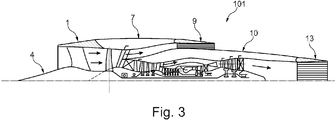
- the nozzles 9, 13 are still placed on the smallest nozzle cross section and always ready to fly in supersonic flight.
- a large first bypass ratio (i.e., ratio of flow through the outer, first bypass passage 8 and flow through the core engine 14) is not suitable for supersonic flight for two reasons; once because of the sinking net thrust with increasing Mach number, and secondly because of the large installation resistance, due to the large end face of the aircraft engine 101 with a high first bypass ratio.
- the speeds for operation in this speed range may be e.g. for the low-pressure shaft 5,500 rpm, for the medium-pressure shaft 8,000 rpm and for the high-pressure shaft 13,000 rpm. Again, the values are of course adapted to the aircraft and the flight conditions.
- turbofan engines are generally suitable with a moderate second bypass ratio (ratio of flow through bypass duct 15 to flow through the corresponding portion of core engine 14) ⁇ 1.
- Such jet engines 101 can provide the thrust necessary for supersonic use without the use of an afterburner.
- the aircraft engines 101 have a small consumption and long range, and bring the desired environmental friendliness for a license for continental supersonic flights.
- Fig. 4 is the configuration of the aircraft engine 101 from the Fig. 2 and Fig. 3 shown for the supersonic flight, in which case a core engine 14 with the inner, second bypass channel 15 is used.
- the low-pressure circuit (fan rotor 5 and the low-pressure turbine 12) is placed in a favorable supersonic mode.
- the dual-circuit twin-shaft core engine 14, on the other hand, is operated at high performance with the second bypass ratio of about one.
- the additional inlet 2 works supersonically closed.
- the convergent-divergent nozzles 9, 13 are now maximally open, i. it is a maximum cross section released.
- the fan rotor 5 Due to the low-pressure turbine 12, with a suitable position of the Vorleitrades 17, the Nachleitrades 18 and the fan rotor 5, only a small power is delivered, which is sufficient to adapt to the speed of the low pressure shaft, a pressure ratio at the fan rotor 5 of about 1.15 to 1.17 Afford. This is sufficient to cover the shock losses from the inlet in supersonic position and the pressure losses from the outer bypass channel 8 and the outer nozzle 9 off. As a result, the fan rotor 5 thus provides a minimum effective thrust; There is minimal effective thrust in the secondary circle.
- the flow in the inlet channel after the inlet neck is in the subsonic region and has a radially uniform distribution of the flow parameters in front of the fan rotor 5. This distribution is secured by the opened outer nozzle 9. Due to the maximum cross-sectional opening nozzle 9, the largest proportion of air from the air inlet flows undisturbed through the outer bypass channel 8 with only a slightly greater back pressure than the dynamic pressure of the undisturbed supersonic flow of the aircraft engine 101 before the inlet.
- the engine governor In supersonic mode, the engine governor, not shown here, intentionally sets the outer sidestream 8 to a minimum thrust (i.e., the net thrust approaches the installation resistance). Thereby, with minimal additional fuel consumption (for driving the fan rotor 5 in supersonic mode), the aircraft engine 101 is "shrunk" to an aircraft engine 101 having a second bypass ratio of 1 ".
- the outer nacelle 7 of this aircraft engine 101 i. the nacelle 7, which is relevant to the installation losses, is reduced to the core engine cowling 10 with a smaller diameter.
- the thus converted by control or regulation turbofan engine 101 is particularly suitable for quiet, economical and clean supersonic flight.
- the engine control sets the twin-shaft core engine 14 (second bypass ratio approx. 1) to supersonic cruise power.
- the total throughput of the core engine 14 (less than 50% of the inlet flow rate, in particular 42% of the inlet flow rate) secures by relaxation through the appropriately controlled low-pressure turbine 12 and then through the maximum open convergent divergent nozzle 13 the necessary and clean thrust for supersonic cruise.
- the speeds for operation in the supersonic range may be 4000 rpm for the low-pressure shaft, 8,200 rpm for the medium-pressure shaft and 13,500 rpm for the high-pressure shaft, for example.
- the adaptive aircraft engine 101 can thus be optimally adapted to the respective flow conditions in the entire operating range.
- Ma numbers Fig. 2 . 3
- the adaptive aircraft engine 101 provides the fan rotor 5 and the outer part of the aircraft engine 101 an important thrust component.
- the large-area portions of the aircraft engine 101 in the flow cross section are "switched off" for supersonic flight (see Fig. 4 ).
- the large, in particular maximum opening of the outer nozzle 9 and the configuration of the aircraft engine 101 described here thus has the effect that the parts of the aircraft engine 101 outside the core engine 14 have no appreciable flow resistance.
- the thrust is then essentially only from the core engine 14th
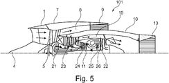
- a further embodiment is shown, which shows a variation of the embodiments shown so far.
- a high-performance gear 21 - designed as a planetary gear - is provided, which is arranged between fan rotor 5 and the low-pressure shaft 11.
- the high-performance transmission 21 is a differential ( Powergearbox (DPGB)).
- the fan rotor 5 can be operated at a lower speed than the low-pressure turbine 22 due to the interposed high-performance transmission 21.
- the fan rotor 5 has adjustable blades.
- the outer diameter of the outer nacelle 7 at the air inlet lip 7 are between 100 cm and 170 cm.
- the outer diameter at the primary nozzle 13 may be between 80 cm and 120 cm.
- the aircraft engine 101 has a medium-pressure compressor 23, a high-pressure compressor 24, a high-pressure turbine 25 and the low-pressure turbine 22.
- the power input into the high-performance transmission 21 via the low pressure shaft 11 (see also Fig. 6 ).
- the planets 33 of the high-performance transmission 21 drive the medium-pressure compressor 23.
- the outer ring 31 of the planetary gear 21 drives the fan rotor 5.
- a portion of the power requirement of the high-pressure compressor 24 is supplied via the sun gear 32 of the planetary gear 21.
- the power consumption of High-pressure compressor 24 thus takes place via the high-pressure turbine 25 (P HDT ) and the high-performance transmission 21 (P ad ).
- the speed ratio of the high-performance transmission 21, the angle of inclination of the rotor blades of the fan rotor 5 and the cross-sectional geometries of the primary nozzle 13 and the secondary nozzle 9 are thus available as manipulated variables (or design variables) for controlling the aircraft engine.
- the low-pressure turbine 22 drives both the high-performance transmission 21, the fan rotor 5 and the medium-pressure compressor 23.
- the additional power P ad corresponds to the difference between the power consumption of the high-pressure compressor 24 and the power output of the high-pressure turbine 25.
- the ratio of the ring diameter of the high power transmission 21 to the planetary diameters may be ⁇ 2.12.
- the high performance gear 21 weighs about 300 kg.
- Fig. 6 is schematically the coupling of the shafts, compressors and turbines of the embodiment according to Fig. 5 shown.
- the low pressure shaft 11 rotates in the specified direction. Before, ie in Fig. 6 To the left of the high-performance transmission 21 (designed as a planetary gear), the low-pressure shaft 11 is connected to the carrier 30 of the planetary gear 21. The shaft of the medium-pressure compressor 23 is driven via the carrier 30 (in Fig. 6 indicated by arrow).
- Power is transmitted to the high pressure compressor 24 via the sun gear 32 of the planetary gear 21.
Landscapes
- Engineering & Computer Science (AREA)
- Chemical & Material Sciences (AREA)
- Combustion & Propulsion (AREA)
- Mechanical Engineering (AREA)
- General Engineering & Computer Science (AREA)
- Physics & Mathematics (AREA)
- Fluid Mechanics (AREA)
- Aviation & Aerospace Engineering (AREA)
- Structures Of Non-Positive Displacement Pumps (AREA)
Abstract
Description
- Die Erfindung betrifft ein adaptives Flugzeugtriebwerk mit den Merkmalen des Anspruchs 1 und ein Flugzeug mit den Merkmalen des Anspruchs 16.
- Es ist bekannt, dass Flugzeugtriebwerke bei Unterschall- und Überschallbetrieb unterschiedliche Charakteristiken aufweisen müssen, um effizient zu funktionieren. Für den Flugbetrieb ist es sinnvoll, einen möglichst hohen Schub relativ zur einströmenden Luft zu haben. Dies bedingt aber, dass beim Start sehr hohe Strahlgeschwindigkeiten vorliegen müssen, was mit einer hohen Geräuschentwicklung einhergeht. Ziel ist es dabei, dass die Prozessführung so angepasst wird, dass im Gesamtbereich vom Start bis zum Überschallflug eine entsprechend angepasste Charakteristik vorliegt. So sind sogenannte Variable Cycle Engines (VCE) bekannt, bei denen insbesondere das Bypassverhältnis des Flugzeugtriebwerks adaptierbar ist. Dabei geht der Stand der Technik (z.B. Müller, Luftstrahltriebwerke, 1997, Seiten 312-313) davon aus, dass das Bypassverhältnis bei geringen Ma-Zahlen groß und bei hohen Ma-Zahlen klein ist.
- Es besteht die Aufgabe, neue und effizientere Flugzeugtriebwerke zu schaffen. Diese Aufgabe wird durch ein Flugzeugtriebwerk mit den Merkmalen des Anspruchs 1 gelöst.
- Dabei weist das Flugzeugtriebwerk einen ersten, inneren Nebenstromkanal in einem Kerntriebwerk auf. Ein zweiter, äußerer Nebenstromkanal umgibt den ersten Nebenstromkanal wenigstens teilweise. Adaptionsmittel, insbesondere adaptive Düsen (d.h. Düsen mit einem adaptiv anpassbaren Querschnitt) dienen dabei der Änderung eines durchströmten Querschnitts des Kerntriebwerks mit dem ersten Nebenstromkanal und der Änderung des durchströmten Querschnitts des zweiten Nebenstromkanals in Abhängigkeit von der Fluggeschwindigkeit. Durch die Verwendung von zwei Nebenstromkanälen in Verbindung mit den Adaptionsmitteln, insbesondere adaptive Düsen für die Querschnitte kann das Flugzeugtriebwerk besonders effizient bei Unter- als auch bei Überschall betrieben werden, da der Strömungswiderstand adaptiv an die jeweilige Fluggeschwindigkeit eingestellt werden kann.
- In einer Ausführungsform dient eine innere, primäre Düse zur Änderung des Querschnitts des Kerntriebwerks mit dem ersten Nebenstromkanal und eine zweite, sekundäre Düse zur Änderung des Querschnitts des zweiten Nebenstromkanals, wobei für den Nettoschub des gesamten Flugzeugtriebwerks


- In einer Ausführungsform ist mit der äußeren, sekundären Düse ein durchströmter Querschnitt des zweiten, äußeren Nebenstromkanals bei Überschallströmung, insbesondere bei Ma > 1,4, vergrößerbar, insbesondere maximierbar. Durch die Vergrößerung des mindestens einen Querschnitts kann der Strömungswiderstand der äußeren Teile des Flugzeugtriebwerks bei hohen Geschwindigkeiten minimiert werden. Entsprechend ist bei einer alternativen oder zusätzlichen Ausführungsform mit der äußeren, sekundären Düse ein durchströmter Querschnitt des zweiten Nebenstromkanals bei Unterschallströmung, insbesondere bei Ma < 0,8 verkleinerbar, insbesondere minimierbar.
- In einer weiteren Ausführungsform ist mit der sekundären Düse der durchströmte Querschnitt des zweiten Nebenstromkanal so vergrößerbar, dass bei Überschallströmung die Differenz zwischen dem Nettoschub der sekundären Düse (Fsekundär, effektiv') und dem Installationswiderstand des sekundären Kreises (IDsekundär) - d.h. der effektive Schub (F-sekundär, effektiv) der sekundären Düse - klein wird, insbesondere minimal wird.
- Wenn in einer Ausführungsform des adaptiven Flugzeugtriebwerks im Einlaufbereich des Flugzeugtriebwerks ein Zusatzeinlauf vorgesehen ist, kann dieser bei Unterschallbedingungen geöffnet und bei Überschallbedingungen geschlossen werden.
- Für die Einstellung der jeweiligen Betriebsbedingungen ist in einer Ausführungsform ein Fanrotor, mindestens ein steuer- oder regelbares Fannachleitrad, mindestens ein steuer- oder regelbares Vorleitrad einer Niederdruckturbine und / oder mindestens ein steuer- oder regelbares Nachleitrad einer Niederdruckturbine vorgesehen. Zusammen mit den insbesondere durch Düsen einstellbaren Querschnitten kann hier die jeweils eine Anpassung an die notwendigen Betriebsbedingungen vorgenommen werden.
- Zusätzlich oder alternativ kann eine Ausführungsform einen Fanrotor aufweisen, der mit einem Hochleistungsgetriebe gekoppelt ist und über eine Turbinenstufe antreibbar ist. Dabei kann der Fanrotor insbesondere verstellbare Schaufeln aufweisen. Durch den Einsatz des Hochleistungsgetriebes können der Fanrotor und die antreibende Turbinenstufe mit jeweils optimierten Drehzahlen betrieben werden.
- In einer weiteren Ausführungsform ist das Flugzeugtriebwerk so ausgebildet, dass es nachbrennerfrei ist. Der Betrieb eines Nachbrenners ist sehr laut, so dass insbesondere ein nachbrennerfreies Zivilflugzeug unter weniger Auflagen betreibbar ist. Auch wird durch diese Maßnahme der Ausstoß von NOX-Gasen reduziert.
- In einer Ausführungsform ist für den äußeren Nebenstromkanal im Unterschallbereich ein Bypassverhältnis

- Bei einer Ausführungsform ist eine Regelungs- oder Steuerungsvorrichtung vorgesehen, mit der die Einstellung der Adaptionsmittel, insbesondere der primären und / oder sekundären Düsen, des mindestens einen Fannachleitrades, des mindestens einen Vorleitrades der Niederdruckturbine und / oder des mindestens einen Nachleitrades der Niederdruckturbine in Abhängigkeit von der Geschwindigkeit des Flugzeugtriebwerk betrieben werden kann. So kann durch eine gemeinsame Einstellung (z.B. durch eine zentrale Steuerung, wie der EEC) der primären und sekundären Düsen, des Fannachleitrades, des Vorleitrades der Niederdruckturbine und des Nachleitrades der Niederdruckturbine eine optimale Wirkung erzielt werden.
- In einer weiteren Ausführungsform ist die Niederdruckturbine mindestens teilweise von einer Strömung aus einer Brennkammer und einer Strömung aus dem inneren Nebenstromkanal antreibbar.
- Bei einer weiteren Ausführungsform ist eine äußere Gondel und / oder das Kerntriebwerk achsensymmetrisch ausgebildet.
- Bei einer weiteren Ausführungsform weist das adaptive Flugzeugtriebwerk ein Zweistrom, Drei-Wellentriebwerk mit zwei Nebenstromkanälen auf, insbesondere mit einer Mischvorrichtung für eine Strömung aus der Brennkammer und einer Strömung aus dem inneren Nebenstromkanal, wobei die Mischvorrichtung in Strömungsrichtung vor der Niederdruckturbine angeordnet ist.
- Die Aufgabe wird auch durch ein Flugzeug mit den Merkmalen des Anspruchs 14 gelöst. In einer Ausführungsform ist das mindestens eine Flugzeugtriebwerk am Heck, insbesondere oberhalb einer Tragfläche des Flugzeugs angeordnet ist.
- In Zusammenhang mit den in den Figuren dargestellten Ausführungsbeispielen wird die Erfindung erläutert. Dabei zeigt
- Fig. 1
- den Aufbau eines Flugzeugs mit einer Ausführungsform eines Flugzeugtriebwerks für den Unter- und Überschallbetrieb;
- Fig. 2
- einen Querschnitt durch eine Ausführungsform des Flugzeugtriebwerks in der Arbeitsposition für niedrige Machzahlen;
- Fig. 3
- einen Querschnitt durch eine Ausführungsform des Flugzeugtriebwerks in der Arbeitsposition für hohen Unterschallflug;
- Fig. 4
- einen Querschnitt durch eine Ausführungsform des Flugzeugtriebwerks in der Arbeitsposition für Überschallbetrieb;
- Fig. 5
- einen Querschnitt einer Ausführungsform mit einem Hochleistungsgetriebe;
- Fig. 6
- eine schematische Darstellung der Wellenanbindung gemäß der Ausführungsform in
Fig. 5 . - In
Fig. 1 ist beispielhaft ein Flugzeug 100 dargestellt, das für eine Reisegeschwindigkeit von Ma = 1,75 ausgelegt ist. Im Folgenden sind insbesondere alle Zahlenwerte im lediglich beispielhaft zu verstehen. Ausführungsformen der Flugzeugtriebwerke 101 sind z.B. auch in Flugzeugen 100 mit anderen Dimensionen einsetzbar. - Das Flugzeug 100 gemäß der dargestellten Ausführungsform ist ein Supersonic Businessjet SSBJ. Dieser verfügt dabei über adaptive Flugzeugtriebwerke 101, die einen Flugbetrieb zulassen, bei dem der Lufteinlass der jeweiligen Fluggeschwindigkeit (z.B. Ma = 0 bis 1,75) angepasst ist, wie dies in der Folge noch beschrieben wird.
- Die adaptiven Flugzeugtriebwerke 101 sind als Zweikreis-Dreiwellen-Flugzeugtriebwerke ausgebildet und oberhalb der Tragflächen 102 angeordnet. Die Flugzeugtriebwerke 101 weisen eine Länge von ca. 7 m auf. Der Durchmesser einer Nacelle 7 (äußere Gondel) der Flugzeugtriebwerke 101 beträgt ca. 1,9 m. Der Durchmesser einer Kerntriebwerksverkleidung 10 beträgt 1,4 m.
- Das Flugzeug 100 weist eine Rumpflänge von 36 m und eine Flügelspannweite von 21 m auf. Die gesamte Flügelfläche beträgt 120 m2. Als maximales Startgewicht werden 100.000 Ib (45,4 t) angenommen.
- Das dargestellte Flugzeug 100 weist eine für den Überschallflug besonders ausgebildete, lanzenartige, im Querschnitt flachgeformte Flugzeugnase auf. Andere Ausführungsformen des Flugzeugs 100 können auch andere Abmessungen und / oder Formen haben.
- Am Einlauf der adaptiven Flugzeugtriebwerke 101 sind jeweils konische Einlaufzentralkörper 4 vorgesehen, die radial von einer Einlauflippe 1 umgeben werden (siehe auch
Fig. 2 ). Der Einlauf kann in anderen Ausführungsformen auch anders gestaltet sein, wie dies z.B. bei der Concorde der Fall war. - Am hinteren Ende der adaptiven Flugzeugtriebwerke 101 sind jeweils zwei Düsen 9, 13 angeordnet, deren Querschnitte konvergent-divergent adaptiv eingestellt werden können, was im Zusammenhang mit den
Fig. 2 bis 4 noch näher dargestellt wird. - Diese beiden Flugzeugtriebwerke 101 weisen jeweils einen maximalen Startschub von 20.000 Ibf (88.964,4 N) auf. Der Schub bei der nominellen Reisefluggeschwindigkeit von Ma = 1,75 beträgt jeweils 6.000 Ibf (26.689,3 N). Hier beträgt der Schub der Reisefluggeschwindigkeit 30% des Schubs beim Start. Wie oben bereits angemerkt, können andere Flugzeuge mit anderen Ausführungsformen der Flugzeugtriebwerke 101 andere Werte für den Schub und die Geschwindigkeiten aufweisen.
- Das hier beschriebene Flugzeug 100 und seine Aggregate sind lediglich beispielhaft zu verstehen, so dass die adaptiven Flugzeugtriebwerke 101 auch an anders konstruierten oder dimensionierten Zivil- oder Militärflugzeugen angeordnet werden können. Insbesondere können auch die Größen- und / oder Leistungsangaben der Flugzeugtriebwerke 101 bei anderen Ausführungsformen anders ausgebildet sein. Auch ist es möglich, dass mehr als zwei der adaptiven Flugzeugtriebwerke 101 an einem Flugzeug 100 verwendet werden.
- Durch die adaptiven Flugzeugtriebwerke 101 wird gewährleistet, dass beim Start und Unterschallflug (z.B. Ma < 0,8) ein Fantriebwerk mit einem relativ hohen Bypassverhältnis vorliegt. Damit werden der Startlärm und der Brennstoffverbrauch reduziert. Beim Überschallflug (z.B. Ma > 1,4) wird durch geeignete Querschnittsveränderungen der Düsen 9, 13, die mit zwei Nebenstromkanälen 8, 15 zusammenwirken, sichergestellt, dass der Strömungswiderstand der Flugzeugtriebwerke 101 gering ist. Die äußere Düse 9 liegt stromabwärts des äußeren Nebenstromkanals 8, die innere Düse 13 liegt stromabwärts des inneren Nebenstromkanals 15 und stromabwärts einer Niederdruckturbine 12.
- Dabei ist die Niederdruckturbine 12 so angeordnet, dass sie nicht nur den ausströmenden Gasen aus einer Brennkammer des Kerntriebwerkes 14, sondern auch der Strömung im inneren Nebenstromkanal 15 ausgesetzt ist, d.h. beide Strömungen treiben die Niederdruckturbine 12 an. Vor der Niederdruckturbine 12 ist eine Mischvorrichtung 16 - z.B. eine Mischkammer - angeordnet, in der die beiden Strömungen sich mischen können. Somit liegt eine Strömung vor, bei der die Strömung aus dem inneren Nebenstromkanal 15 und der Mitteldruckturbine 19 in der Mischvorrichtung 16 gemischt werden. Die Strömung des Kerntriebwerks 14 beaufschlagt dann die Niederdruckturbine 12.
- In
Fig. 2 ist ein dreiwelliges Mantelstromstrahltriebwerk 101 in einem Halbschnitt dargestellt. - Das Flugzeugtriebwerk 101 weist außen eine relativ kurze Gondel 7 (Nacelle) auf, die ein Kerntriebwerk 14 mit seiner Kerntriebwerksverkleidung 10 umgibt. Dabei zeigt
Fig. 2 das adaptive Flugzeugtriebwerk 101 in einer Konfiguration, wie sie beim Start oder einem Flug mit niedriger Ma-Zahl (z.B. Ma < 0,8) vorliegt. Das Flugzeugtriebwerk 101 weist hier die beiden Nebenstromkanäle 8, 15 auf, den äußeren, zweiten Nebenstromkanal 8 - das Kerntriebwerksgehäuse 10 mindestens teilweise umgebend - und den inneren, ersten Nebenstromkanal 15 im Kerntriebwerk 14. - In der dargestellten Ausführungsform ist das Flugzeugtriebwerk 101 rotationsymmetrisch um die strichpunktierte Mittelachse ausgebildet. Bei anderen Ausführungsformen kann insbesondere die Gondel 7 von einer rotationssymmetrischen Form abweichen, wie dies z.B. von der Boeing 737 - 600 (next generation) bekannt ist.
- Der Lufteinlauf des Flugzeugtriebwerks 101 vor dem Fanrotor 5 (hier mit einem Durchmesser von ca. 1,4 m) umfasst die Lufteinlauflippe 1, einen Zusatzeinlauf 2 (hier in einer geöffneten Position dargestellt), Einlaufstreben 3 und den an den Einlaufstreben 3 befestigten konischen Einlaufzentralkörper 4. Damit liegt ein an sich bekannter regelbarer Überschalleinlauf vor, bei dem durch Verschiebung der äußeren Einlauflippe 1 nach vorne eine variable Einlaufgeometrie bereitgestellt wird.
- Durch die Öffnung des Zusatzeinlaufs 2 wird im Startflug und im niedrigem Unterschallbereich (z.B. Ma < 0,8) ein schwingungsfreier Fanbetrieb ermöglicht.
- Hinter dem Fanrotor 5 ist ein steuer- oder regelbares (adaptives) Fannachleitrad 6 angeordnet. Der Fanrotor 5 wird über eine Niederdruckwelle 11 von einer Niederdruckturbine 12 (ein- oder zweistufig ausgeführt) am hinteren Ende des Flugzeugtriebwerks 101 angetrieben. Zur Anpassung an dem jeweiligen Lastzustand, sind für die Niederdruckturbine 12 steuer- oder regelbare (adaptive) Vorleiträder 17 (NGV) und ein steuer- oder regelbares (adaptive) Nachleitrad 18 (OGV) vorgesehen. Die Niederdruckturbine 12 wird vom Gasgemisch des Zweiwellen-Kerntriebwerks 14 angetrieben. Danach entspannt sich der Gasstrom der Niederdruckturbine 12 durch die steuer- oder regelbare (d.h. adaptive) Primärdüse 13 nach außen.
- Stromab vom steuer- oder regelbaren Fannachleitrad 6, teilt sich der Gesamtdurchsatz der Luft in zwei Teile.
- Der Hauptanteil der eintretenden Luft durchströmt den äußeren Nebenstromkanal 8 und entspannt sich danach durch die variable (d.h. adaptive) konvergente-divergente Düse 9. Für den Startzustand (MTO) beträgt das erste Bypassverhältnis, d.h., das Verhältnis zwischen der Strömung durch den äußeren Nebenstromkanal 8 und dem Strom durch das Kerntriebwerk 14, ungefähr 1,4, oder kleiner als 1,6.
- Der kleinere Kernmassenstrom wird zum Kerntriebwerk 14 (mit steuer- oder regelbarem Vorleitrad) geführt. Das Kerntriebwerk 14 ist ein Zweikreis-Zweiwellen-Mantelstromtriebwerk mit dem inneren Nebenstromkanal 15 und mit einer Mischkammer als Mischvorrichtung 16. Es handelt sich dabei um ein an sich bekanntes Mantelstromstrahltriebwerk (mit einer Stufenkonfiguration 3+6/1+1) mit einem zweiten Bypassverhältnis (d.h. das Nebenstromverhältnis im Kerntriebwerk 14) von ungefähr 1. Das Kerntriebwerk 14 ist nachbrennerfrei, was sich insbesondere geräuschmindernd auswirkt. Auch wirkt sich dies positiv auf die Sparsamkeit und die NOX-Emissionen aus. Die Stufenkonfiguration kann variieren, so dass z.B. auch eine 2+6 / 1+1 Konfiguration möglich ist.
- Das Strömungsgemisch aus der Mischvorrichtung 16, d.h. ein Gemisch einer Strömung aus der Mitteldruckturbine 19 des Kerntriebwerks 14 mit der Strömung aus dem inneren Nebenstromkanal 15, wird zur Niederdruckturbine 12 geführt und dient damit dem Antrieb des Fanrotors 5.
- Die Niederdruckturbine 12 wird dabei von einem relativ großen Durchsatz angetrieben, und arbeitet dabei verhältnismäßig kalt und kann dementsprechend grundsätzlich auch einstufig ausgelegt werden. In der in
Fig. 2 darstellten Ausführungsform ist die Niederdruckturbine 12 zweistufig ausgebildet. Die Drehzahlen für einen Betrieb im Unterschallbereich können z.B. für die Niederdruckwelle 5.700 U/min, für die Mitteldruckwelle 8.200 U/min und für die Hochdruckwelle 13.500 U/min betragen. - Die Lufteinlauflippe 1 ist in
Fig. 2 deutlich nach vorne geschoben und gibt damit eine Öffnung frei. - Beide Düsen 9, 13 sind in der dargestellten Betriebssituation auf den kleinsten Düsenquerschnitt eingestellt. Zur Einstellung des Düsenquerschnitts dienen jeweils Querschnitts-Verstellmechanismen (z.B. eine verstellbare Schubdüse (Irisdüse)). Die Düsen 9, 13 sind damit unabhängig voneinander regelbar konvergent-divergent ausgebildet.
- Eine Triebwerksregelung hat die relevanten Triebwerkskomponenten (insbesondere den Öffnungszustand des Zusatzeinlaufs 2), entsprechend für den Startflug und den niedrigen Machflugmodus angepasst.
- Im Folgenden wird im Zusammenhang mit
Fig. 3 dargestellt, in welcher Weise eine Anpassung an andere Geschwindigkeitsbereiche erfolgen kann, wobei die Öffnung der Düsen 9, 13 in Abhängigkeit von der Mach-Zahl erfolgt. - Bei höheren Geschwindigkeiten, d.h. im hohen Unterschallflug oder bei Ma von ungefähr 1 passt sich das Flugzeugtriebwerk 101 entsprechend an. Auf die Beschreibung des Flugzeugtriebwerks 101 in der obigen Beschreibung der
Fig. 2 kann Bezug genommen werden. - Im Unterschied zur Konfiguration ist der Zusatzeinlauf 2 nun geschlossen. Die Gondel 7 ist für den kleinsten induzierten Widerstand angepasst.
- Der Fanrotor 5 wird durch den Einlauf mit dem benötigten Luftdurchsatz, bei minimalen Einlassverlusten versorgt. Die Düsen 9, 13 sind weiterhin auf den kleinsten Düsenquerschnitt gestellt und dabei stets bereit im Überschallflug zum Öffnen.
- Ein großes erstes Bypassverhältnis (d.h. Verhältnis von Strömung durch den äußeren, ersten Nebenstromkanal 8 und der Strömung durch das Kerntriebwerk 14) ist aus zwei Gründen für Überschallflug nicht geeignet; einmal wegen des sinkendem Nettoschubs mit steigender Machzahl, und zweitens durch den großen Installationswiderstand, bedingt durch die große Stirnfläche des Flugzeugtriebwerks 101 mit großem ersten Bypassverhältnis.
- Die Drehzahlen für einen Betrieb in diesem Geschwindigkeitsbereich können z.B. für die Niederdruckwelle 5.500 U/min, für die Mitteldruckwelle 8.000 U/min und für die Hochdruckwelle 13.000 U/min betragen. Auch hier gilt, dass die Werte natürlich dem Flugzeug und den Flugbedingungen angepasst werden.
- Für Ma ∼ 1.75 sind Mantelstromstrahltriebwerke grundsätzlich mit einem gemäßigten zweiten Bypassverhältnis (Verhältnis Strömung durch Nebenstromkanal 15 zu Strömung durch den entsprechenden Teil des Kerntriebwerks 14) ∼ 1 geeignet. Es sind Mantelstromstrahltriebwerke mit verhältnismäßig groß ausgelegtem Kerntriebwerk 14. Ein solches Flugzeugtriebwerk 101 kann den für den Überschall nötigen Schub ohne Einsatz eines Nachbrenners leisten. Dadurch haben die Flugzeugtriebwerke 101 einen kleinen Verbrauch und große Reichweite, und bringen die erwünschte Umweltfreundlichkeit für eine Zulassung für kontinentale Überschallflüge.
- In
Fig. 4 ist die Konfiguration des Flugzeugtriebwerks 101 aus denFig. 2 undFig. 3 für den Überschallflug dargestellt, wobei hier ein Kerntriebwerk 14 mit dem inneren, zweiten Nebenstromkanal 15 eingesetzt wird. - Dabei wird der Niederdruckkreis (Fanrotor 5 und die Niederdruckturbine 12) in einen günstigen Überschallmodus gestellt. Das Zweikreis-Zweiwellenkerntriebwerk 14 wird hingegen auf Hochleistung mit dem zweiten Bypassverhältnis von ungefähr 1 betrieben.
- Der Zusatzeinlauf 2 arbeitet im Überschall geschlossen. Die konvergent-divergenten Düsen 9, 13 sind jetzt maximal geöffnet, d.h. es ist ein maximaler Querschnitt freigegeben.
- Durch die Niederdruckturbine 12, bei geeigneter Stellung des Vorleitrades 17, des Nachleitrades 18 und des Fanrotors 5, wird nur eine kleine Leistung geliefert, die ausreicht, um bei angepasster Drehzahl der Niederdruckwelle ein Druckverhältnis am Fanrotor 5 von ca. 1,15 bis 1.17 zu leisten. Dies reicht zur Deckung der Stoßverluste aus dem Einlauf in Überschallstellung und der Druckverluste aus dem äußeren Nebenstromkanal 8 und der äußeren Düse 9 aus. Im Ergebnis liefert somit der Fanrotor 5 einen minimalen effektiven Schub; es liegt minimaler Effektivschub im sekundären Kreis vor.
- Die Strömung im Einlaufkanal nach dem Einlaufhals ist im Unterschallbereich und hat vor dem Fanrotor 5 eine radial gleichförmige Verteilung der Strömungsparameter. Diese Verteilung wird durch die geöffnete äußere Düse 9 gesichert. Auf Grund der auf maximale Querschnittsöffnung eingestellten Düse 9 strömt der größte Luftanteil aus dem Lufteinlass ungestört durch den äußeren Nebenstromkanal 8 mit einem nur etwas größeren Staudruck als der Staudruck der ungestörten Überschallströmung des Flugzeugtriebwerks 101 vor dem Einlauf.
- Nach Entspannung durch die Überschalldüse 9 ergibt die Druckverteilung auf die äußere und innere Kontur der Außengondel (Lufteinlauflippe 1, äußere Gondel 7 und äußere Düse 9) einen resultierenden minimalen Effektivschub, der größer oder gleich dem Strömungswiderstand des äußeren Triebwerkskreis ist.
- Im Überschallmodus setzt die hier nicht dargestellte die Triebwerksreglung den äußeren Nebenstrom 8 gezielt auf einen minimalen Schub (d.h. der Nettoschub nähert sich dem Installationswiderstand an). Dadurch, wird mit minimal zusätzlichem Kraftstoffverbrauch (für das Antreiben des Fanrotors 5 im Überschallmodus) das Flugzeugtriebwerk 101 auf ein Flugzeugtriebwerk 101 mit einem zweiten Bypassverhältnis von 1 "zusammengeschrumpft". Die äußere Gondel 7 dieses Flugzeugtriebwerks 101, d.h. die Gondel 7, die für die Installationsverluste relevant ist, wird auf die Kerntriebwerksverkleidung 10 mit einem kleineren Durchmesser reduziert.
- Das so durch Steuerung oder Regelung transformierte Mantelstromstrahltriebwerk 101 ist für den leisen, sparsamen und sauberen Überschallflug besonders geeignet. Gleichzeitig setzt die Triebwerksreglung das Zweiwellen-Kerntriebwerk 14 (zweites Bypassverhältnis ca. 1) auf Überschallreiseflugleistung. Der Gesamtdurchsatz des Kerntriebwerks 14 (in weniger als 50% des Einlaufdurchsatzes, insbesondere 42% des Einlaufdurchsatzes) sichert durch Entspannung durch die entsprechend geregelte Niederdruckturbine 12 und danach durch die maximal geöffnete konvergent- divergente Düse 13 den nötigen und sauberen Schub für Überschallreiseflug.
- Die Drehzahlen für einen Betrieb im Überschallbereich können z.B. für die Niederdruckwelle 4000 U/min, für die Mitteldruckwelle 8.200 U/min und für die Hochdruckwelle 13.500 U/min betragen.
- Das adaptive Flugzeugtriebwerk 101 kann somit im gesamten Betriebsbereich optimal den jeweiligen Strömungsbedingungen angepasst werden. Bei vergleichsweise niedrigen Ma-Zahlen (
Fig. 2 ,3 ) liefert der Fanrotor 5 und der äußere Teil des Flugzeugtriebwerks 101 einen wichtigen Schubanteil. - Die im Strömungsquerschnitt großflächigen Anteile des Flugzeugtriebwerks 101 werden für den Überschallflug "abgeschaltet" (siehe
Fig. 4 ). Die große, insbesondere maximale Öffnung der äußeren Düse 9 und die hier beschriebene Konfiguration des Flugzeugtriebwerks 101 bewirkt somit, dass die Teile des Flugzeugtriebwerks 101 außerhalb des Kerntriebwerkes 14 keinen nennenswerten Strömungswiderstand haben. Der Schub stammt dann im Wesentlichen nur aus dem Kerntriebwerk 14. - In der
Fig. 5 wird eine weitere Ausführungsform dargestellt, die eine Variation der bisher dargestellten Ausführungsformen dargestellt. Grundsätzlich kann somit auf die obigen Beschreibungen Bezug genommen werden, wobei bei dem Flugzeugtriebwerk 101 hier ein Hochleistungsgetriebe 21 - als Planetenradgetriebe ausgebildet - vorgesehen ist, das zwischen Fanrotor 5 und der Niederdruckwelle 11 angeordnet ist. Das Hochleistungsgetriebe 21 ist ein differentielles Getriebe (Differential Powergearbox (DPGB)). - Wie bei den an sich bekannten Turbofan-Triebwerken kann der Fanrotor 5 auf Grund des zwischengeschalteten Hochleistungsgetriebes 21 mit einer geringeren Drehzahl betrieben werden, als die Niederdruckturbine 22. Der Fanrotor 5 weist verstellbare Schaufeln auf.
- Bei dieser Ausführungsform kann z.B. der Außendurchmesser der äußeren Gondel 7 an der Lufteinlauflippe 7 zwischen 100 cm und 170 cm liegen. Der äußere Durchmesser an der primären Düse 13 kann zwischen 80 cm und 120 cm liegen.
- Des Weiteren verfügt das Flugzeugtriebwerk 101 über einen Mitteldruckverdichter 23, einen Hochdruckverdichter 24, eine Hochdruckturbine 25 und die Niederdruckturbine 22.
- Der Leistungseintrag in das Hochleistungsgetriebe 21 erfolgt über die Niederdruckwelle 11 (siehe auch
Fig. 6 ). Die Planeten 33 des Hochleistungsgetriebes 21 treiben den Mitteldruckverdichter 23 an. Der äußere Ring 31 des Planetengetriebes 21 treibt den Fanrotor 5 an. Ein Teil des Leistungsbedarfs des Hochdruckverdichters 24 wird über das Sonnenrad 32 des Planetengetriebes 21 zugeführt. Die Leistungsaufnahme des Hochdruckverdichters 24 erfolgt somit über die Hochdruckturbine 25 (PHDT) und das Hochleistungsgetriebe 21 (Pad). - Damit stehen als Stellgrößen (oder Designgrößen) für die Regelung des Flugzeugtriebwerks das Drehzahlverhältnis des Hochleistungsgetriebes 21, der Neigungswinkel der Rotorschaufeln des Fanrotors 5 und die Querschnittsgeometrien der primären Düse 13 und der sekundären Düse 9 zur Verfügung.
- Im Folgenden wird ein vereinfachtes Modell mit folgenden Beziehungen angegeben:


- Dabei bedeuten:
- PNDT
- Leistung Niederdruckturbine
- PDPGB
- Leistung Hochleistungsgetriebe
- PMDV
- Leistung Mitteldruckverdichter
- PFan
- Leistung Fan
- Pad
- Zusatzleistung für Hochdruckverdichter
- PHDT
- Leistung Hochdruckturbine
- PHDV
- Leistung Hochdruckverdichter
- NHDT
- Drehzahl Hochdruckturbine
- NNDT
- Drehzahl Niederdruckturbine
- NFan
- Drehzahl Fanrotor
- Wf
- Brennstoffdurchsatz
- f1, f2, f3
- Funktionale Zusammenhänge
- beta
- Fan-Einstellparameter
- η
- Wirkungsgrad des Hochleistungsgetriebes
- Aus dem Modell kann man ersehen, dass die Niederdruckturbine 22 sowohl das Hochleistungsgetriebe 21, den Fanrotor 5 als auch den Mitteldruckverdichter 23 antreibt.
- Die Zusatzleistung Pad entspricht der Differenz zwischen der Leistungsaufnahme des Hochdruckverdichters 24 und der Leistungsabgabe der Hochdruckturbine 25.
- In einer Ausführungsform kann das Verhältnis des Ringdurchmessers des Hochleistungsgetriebes 21 zu den Planetendurchmessern i ≈ 2.12 betragen. Das Hochleistungsgetriebe 21 wiegt ca. 300 kg.
- In der
Fig. 6 ist in schematischer Weise die Kopplung der Wellen, Verdichter und Turbinen der Ausführungsform gemäßFig. 5 dargestellt. - Die Niederdruckwelle 11 dreht in der angegebenen Richtung. Vor, d.h. in
Fig. 6 links vom Hochleistungsgetriebe 21 (als Planetenradgetriebe ausgeführt) ist die Niederdruckwelle 11 mit dem Carrier 30 des Planetenradgetriebes 21 verbunden. Die Welle des Mitteldruckverdichters 23 wird über den Carrier 30 angetrieben (inFig. 6 durch Pfeil dargestellt). - Über den äußeren Ring 31 des Planetenradgetriebes 21 wird der Fanrotor 5 angetrieben (in
Fig. 5 durch Pfeil dargestellt). - Über das Sonnenrad 32 des Planetenradgetriebes 21 wird Leistung an den Hochdruckverdichter 24 übertragen.
-
- 1
- Lufteinlauflippe
- 2
- Zusatzeinlauf
- 3
- Einlaufstreben
- 4
- Einlaufzentralkörper (Konus)
- 5
- Fanrotor
- 6
- steuer- oder regelbares Fannachleitrad
- 7
- äußere Gondel
- 8
- äußerer Nebenstromkanal
- 9
- sekundäre, äußere Düse
- 10
- Kerntriebwerksverkleidung
- 11
- Niederdruckwelle
- 12
- Niederdruckturbine mit variablem Vorleitrad
- 13
- primäre, innere Düse
- 14
- Kerntriebwerk (Zweikreis-Zweiwellentriebwerk)
- 15
- innerer Nebenstromkanal
- 16
- Mischvorrichtung und Mischer des Kerntriebwerks
- 17
- steuer- oder regelbares Vorleitrad
- 18
- steuer- oder regelbares Nachleitrad
- 19
- Mitteldruckturbine
- 22
- Niederdruckturbine
- 21
- Hochleistungsgetriebe
- 23
- Mitteldruckverdichter
- 24
- Hochdruckverdichter
- 25
- Hochdruckturbine
- 30
- Carrier Hochleistungsgetriebe
- 31
- äußeres Rad des Planetenradgetriebes
- 32
- Sonnenrad
- 33
- Planetenrad
- 100
- Flugzeug
- 101
- Flugzeugtriebwerk
- 102
- Tragfläche
Claims (16)
- Adaptives Flugzeugtriebwerk für den Unter- und Überschallbetrieb eines Flugzeuges,
gekennzeichnet durch
einen ersten, inneren Nebenstromkanal (15) in einem Kerntriebwerk (14) des Flugzeugtriebwerks (101) und einen zweiten, äußeren Nebenstromkanal (8), der den ersten Nebenstromkanal (15) wenigstens teilweise umgibt, und Adaptionsmittel, insbesondere verstellbare Düsen (13, 9) für die Änderung eines durchströmten Querschnitts des Kerntriebwerks (14) mit dem ersten Nebenstromkanal (15) und für die Änderung des durchströmten Querschnittes des zweiten Nebenstromkanals (8) in Abhängigkeit von der Fluggeschwindigkeit. - Adaptives Flugzeugtriebwerk, nach mindestens einem der vorhergehenden Ansprüche, dadurch gekennzeichnet, durch eine innere, primäre Düse (13) zur Änderung des Querschnitts des Kerntriebwerks (14) mit dem ersten Nebenstromkanal (15) und eine zweite, sekundäre Düse (9) zur Änderung des durchströmten Querschnitts des zweiten Nebenstromkanals (8), wobei für den Nettoschub des gesamten Flugzeugtriebwerks


- Adaptives Flugzeugtriebwerk nach Anspruchs 1 oder 2, dadurch gekennzeichnet, dass mit der äußeren, sekundären Düse (9) mindestens ein durchströmter Querschnitt des zweiten Nebenstromkanals (8) bei Überschallströmung, insbesondere bei Ma > 1,4, vergrößerbar, insbesondere maximierbar ist.
- Adaptives Flugzeugtriebwerk nach mindestens einem der vorhergehenden Ansprüche, dadurch gekennzeichnet, dass mit der äußeren, sekundären Düse (9) mindestens ein durchströmter Querschnitt des zweiten Nebenstromkanals (8) bei Unterschallströmung, insbesondere bei Ma < 0,8 verkleinerbar ist, insbesondere minimierbar ist.
- Adaptives Flugzeugtriebwerk nach mindestens einem der vorhergehenden Ansprüche, dadurch gekennzeichnet, dass mit der äußeren, sekundären Düse (9) der durchströmte Querschnitt des zweiten Nebenstromkanals (8) so vergrößerbar ist, dass bei Überschallströmung die Differenz zwischen dem Nettoschub der sekundären Düse (Fsekundär, effektiv') und dem Installationswiderstand des sekundären Kreises (IDsekundär), d.h. der effektive Schub (Fsekundär, effektiv) der sekundären Düse (9) klein wird.
- Adaptives Flugzeugtriebwerk nach mindestens einem der vorhergehenden Ansprüche, dadurch gekennzeichnet, dass im Einlaufbereich des Flugzeugtriebwerks (101) ein Zusatzeinlauf (2) vorgesehen ist, der bei Unterschallbedingungen öffenbar ist und bei Überschallbedingungen schließbar ist.
- Adaptives Flugzeugtriebwerk nach mindestens einem der vorhergehenden Ansprüche, gekennzeichnet durch einen Fanrotor (5), mindestens ein steuer- oder regelbares Fannachleitrad (6), mindestens ein steuer- oder regelbares Vorleitrad (17) einer Niederdruckturbine (12) und / oder mindestens ein steuer- oder regelbares Nachleitrad (18) einer Niederdruckturbine (12).
- Adaptives Flugzeugtriebwerk nach mindestens einem der vorhergehenden Ansprüche, gekennzeichnet durch einen Fanrotor (5), der mit einem Hochleistungsgetriebe (21) gekoppelt ist und über eine Turbinenstufe (22) antreibbar ist, insbesondere mit einem Fanrotor (5) mit verstellbaren Schaufeln, wobei insbesondere ein Leistungseintrag in das Hochleistungsgetriebe (21) über die Niederdruckwelle (11) erfolgt, der Mitteldruckverdichter (23) über Planeten des Hochleistungsgetriebes (21) antreibbar sind, der Fanrotor (5) über den Ring des Planetengetriebes (21) antreibbar ist und ein Teil des Leistungsbedarfs des Hochdruckverdichters (24) über das Sonnenrad des Planetengetriebes (21) zuführbar ist.
- Adaptives Flugzeugtriebwerk nach mindestens einem der vorhergehenden Ansprüche, dadurch gekennzeichnet, dass es nachbrennerfrei ist.
- Adaptives Flugzeugtriebwerk nach mindestens einem der vorhergehenden Ansprüche, dadurch gekennzeichnet, dass im Unterschallbereich ein Bypassverhältnis

- Adaptives Flugzeugtriebwerk nach mindestens einem der vorhergehenden Ansprüche, dadurch gekennzeichnet, dass für den inneren Nebenstromkanal (15) im Über- und Unterschallbereich ein Bypassverhältnis zwischen 1,2 und 0,8, insbesondere 1 einstellbar ist.
- Adaptives Flugzeugtriebwerk nach mindestens einem der vorhergehenden Ansprüche, gekennzeichnet durch eine Regelungs- oder Steuerungsvorrichtung für die Einstellung der Adaptionsmittel, insbesondere der primären und / oder sekundären Düsen (13, 8), des mindestens einen Fannachleitrades (6), des mindestens einen Vorleitrades (17) der Niederdruckturbine (12) und / oder des mindestens einen Nachleitrades (18) der Niederdruckturbine (12) in Abhängigkeit von der Geschwindigkeit, bei der das Flugzeugtriebwerk (101) betrieben wird.
- Adaptives Flugzeugtriebwerk nach mindestens einem der vorhergehenden Ansprüche, dadurch gekennzeichnet, dass die Niederdruckturbine (12, 22) mindestens teilweise von einer Strömung aus einer Brennkammer und einer Strömung aus dem inneren Nebenstromkanal (15) antreibbar ist.
- Adaptives Flugzeugtriebwerk nach mindestens einem der vorhergehenden Ansprüche, dadurch gekennzeichnet, dass eine äußere Gondel (7) und / oder das Kerntriebwerk (14) achsensymmetrisch ausgebildet sind.
- Adaptives Flugzeugtriebwerk nach mindestens einem der vorhergehenden Ansprüche, dadurch gekennzeichnet, dass ein Zweistrom, Drei-Wellentriebwerk mit zwei Nebenstromkanälen (8, 15) aufweist, insbesondere mit einer Mischvorrichtung (16) für eine Strömung aus der Brennkammer und einer Strömung aus dem inneren Nebenstromkanal (15), wobei die Mischvorrichtung (16) in Strömungsrichtung vorder Niederdruckturbine (12) angeordnet ist.
- Flugzeug mit mindestens einem adaptiven Flugzeugtriebwerk (101) nach einem der Ansprüche 1 bis 15, insbesondere mit mindestens einem Flugzeugtriebwerk (101) am Heck, insbesondere oberhalb einer Tragfläche (102) Flugzeugs (100).
Applications Claiming Priority (1)
| Application Number | Priority Date | Filing Date | Title |
|---|---|---|---|
| DE102015209892.3A DE102015209892A1 (de) | 2015-05-29 | 2015-05-29 | Adaptives Flugzeugtriebwerk und Flugzeug mit einem adaptiven Triebwerk |
Publications (2)
| Publication Number | Publication Date |
|---|---|
| EP3098426A1 true EP3098426A1 (de) | 2016-11-30 |
| EP3098426B1 EP3098426B1 (de) | 2019-11-27 |
Family
ID=56108507
Family Applications (1)
| Application Number | Title | Priority Date | Filing Date |
|---|---|---|---|
| EP16171829.1A Active EP3098426B1 (de) | 2015-05-29 | 2016-05-27 | Adaptives flugzeugtriebwerk |
Country Status (3)
| Country | Link |
|---|---|
| US (1) | US10450078B2 (de) |
| EP (1) | EP3098426B1 (de) |
| DE (1) | DE102015209892A1 (de) |
Cited By (2)
| Publication number | Priority date | Publication date | Assignee | Title |
|---|---|---|---|---|
| RU2706524C1 (ru) * | 2018-12-07 | 2019-11-19 | Публичное акционерное общество "ОДК-Уфимское моторостроительное производственное объединение" (ПАО "ОДК-УМПО") | Система охлаждения затурбинных элементов трехконтурного турбореактивного двигателя |
| WO2024121465A1 (fr) * | 2022-12-05 | 2024-06-13 | Safran Aircraft Engines | Turbomachine d'aéronef a triple flux |
Families Citing this family (25)
| Publication number | Priority date | Publication date | Assignee | Title |
|---|---|---|---|---|
| WO2014197030A2 (en) * | 2013-03-12 | 2014-12-11 | United Technologies Corporation | Expanding shell flow control device |
| US10578028B2 (en) | 2015-08-18 | 2020-03-03 | General Electric Company | Compressor bleed auxiliary turbine |
| US10711702B2 (en) * | 2015-08-18 | 2020-07-14 | General Electric Company | Mixed flow turbocore |
| US20180216576A1 (en) * | 2016-10-14 | 2018-08-02 | General Electric Company | Supersonic turbofan engine |
| GB201704173D0 (en) * | 2017-03-16 | 2017-05-03 | Rolls Royce Plc | Gas turbine engine |
| GB201811401D0 (en) | 2018-07-12 | 2018-08-29 | Rolls Royce Plc | Supersonic aircraft propulsion installation |
| CN109139294B (zh) * | 2018-07-25 | 2019-08-23 | 中国航发沈阳发动机研究所 | 一种喷气式航空发动机及其调节方法 |
| US11994089B2 (en) | 2019-04-10 | 2024-05-28 | Rtx Corporation | After-fan system for a gas turbine engine |
| US11846196B2 (en) | 2020-02-21 | 2023-12-19 | Rtx Corporation | After-fan system with electrical motor for gas turbine engines |
| US12129025B1 (en) | 2020-09-02 | 2024-10-29 | Pivotal Supersonic Inc. | Supersonic aircraft |
| US11781479B2 (en) * | 2021-05-06 | 2023-10-10 | Rtx Corporation | Turbofan gas turbine engine with combusted compressor bleed flow |
| US11408343B1 (en) * | 2021-05-06 | 2022-08-09 | Raytheon Technologies Corporation | Turboshaft engine with axial compressor |
| US11492918B1 (en) | 2021-09-03 | 2022-11-08 | General Electric Company | Gas turbine engine with third stream |
| FR3127788B1 (fr) * | 2021-10-04 | 2025-03-21 | Safran Aircraft Engines | Tuyère de sortie équipée de chevrons pour propulseur aéronautique |
| US12421917B2 (en) | 2022-08-02 | 2025-09-23 | General Electric Company | Gas turbine engine with third stream |
| US12577925B2 (en) | 2022-08-02 | 2026-03-17 | General Electric Company | Gas turbine engine with third stream |
| US12565866B2 (en) | 2022-08-02 | 2026-03-03 | General Electric Company | Gas turbine engine with third stream |
| US12486817B2 (en) | 2022-08-02 | 2025-12-02 | General Electric Company | Gas turbine engine with third stream |
| US12560132B2 (en) | 2022-08-02 | 2026-02-24 | General Electric Company | Gas turbine engine with third stream |
| US12577926B2 (en) | 2022-08-02 | 2026-03-17 | General Electric Company | Gas turbine engine |
| US12618384B2 (en) | 2022-08-02 | 2026-05-05 | General Electric Company | Gas turbine engine having a bypass passage, a fan duct, and a core duct |
| US12571358B2 (en) | 2022-08-02 | 2026-03-10 | General Electric Company | Gas turbine engine with third stream |
| US12410763B2 (en) | 2022-08-02 | 2025-09-09 | General Electric Company | Gas turbine engine with third stream |
| US12516647B2 (en) | 2022-08-02 | 2026-01-06 | General Electric Company | Gas turbine engine with third stream |
| US12031504B2 (en) | 2022-08-02 | 2024-07-09 | General Electric Company | Gas turbine engine with third stream |
Citations (8)
| Publication number | Priority date | Publication date | Assignee | Title |
|---|---|---|---|---|
| DE2624164A1 (de) * | 1975-06-02 | 1976-12-23 | Gen Electric | Zyklusvariables gasturbinentriebwerk |
| DE2638882A1 (de) * | 1975-12-01 | 1977-06-08 | Gen Electric | Ausstroemduese mit austrittskonus und klappe fuer variablen betriebszyklus und verfahren zum betrieb derselben |
| US4085583A (en) * | 1975-03-31 | 1978-04-25 | The Boeing Company | Method for selectively switching motive fluid supply to an aft turbine of a multicycle engine |
| US5404713A (en) * | 1993-10-04 | 1995-04-11 | General Electric Company | Spillage drag and infrared reducing flade engine |
| US20030132342A1 (en) * | 2002-01-11 | 2003-07-17 | Koncsek Joseph L. | Method and apparatus for controlling aircraft inlet air flow |
| US20060236675A1 (en) * | 2005-04-20 | 2006-10-26 | Mtu Aero Engines Gmbh | Jet engine with compact arrangement of fan |
| US20070000232A1 (en) * | 2005-06-29 | 2007-01-04 | General Electric Company | Gas turbine engine and method of operating same |
| US20150113941A1 (en) * | 2013-10-24 | 2015-04-30 | United Technologies Corporation | Translating outer cowl flow modulation device and method |
Family Cites Families (13)
| Publication number | Priority date | Publication date | Assignee | Title |
|---|---|---|---|---|
| US3514952A (en) * | 1964-07-01 | 1970-06-02 | Us Air Force | Variable bypass turbofan engine |
| GB1069033A (en) * | 1965-01-30 | 1967-05-17 | Rolls Royce | Improvements in or relating to gas turbine jet propulsion engines |
| US3854286A (en) * | 1971-11-08 | 1974-12-17 | Boeing Co | Variable bypass engines |
| US3879941A (en) * | 1973-05-21 | 1975-04-29 | Gen Electric | Variable cycle gas turbine engine |
| US3841091A (en) * | 1973-05-21 | 1974-10-15 | Gen Electric | Multi-mission tandem propulsion system |
| US4175384A (en) * | 1977-08-02 | 1979-11-27 | General Electric Company | Individual bypass injector valves for a double bypass variable cycle turbofan engine |
| US5305599A (en) * | 1991-04-10 | 1994-04-26 | General Electric Company | Pressure-ratio control of gas turbine engine |
| US5261227A (en) * | 1992-11-24 | 1993-11-16 | General Electric Company | Variable specific thrust turbofan engine |
| US6511866B1 (en) * | 2001-07-12 | 2003-01-28 | Rjr Polymers, Inc. | Use of diverse materials in air-cavity packaging of electronic devices |
| US20070000023A1 (en) * | 2005-06-15 | 2007-01-04 | Helen Sieme | Protective device and method for use |
| US7614210B2 (en) * | 2006-02-13 | 2009-11-10 | General Electric Company | Double bypass turbofan |
| US8393158B2 (en) * | 2007-10-24 | 2013-03-12 | Gulfstream Aerospace Corporation | Low shock strength inlet |
| US20110171007A1 (en) | 2009-09-25 | 2011-07-14 | James Edward Johnson | Convertible fan system |
-
2015
- 2015-05-29 DE DE102015209892.3A patent/DE102015209892A1/de not_active Withdrawn
-
2016
- 2016-05-27 EP EP16171829.1A patent/EP3098426B1/de active Active
- 2016-05-31 US US15/168,429 patent/US10450078B2/en active Active
Patent Citations (8)
| Publication number | Priority date | Publication date | Assignee | Title |
|---|---|---|---|---|
| US4085583A (en) * | 1975-03-31 | 1978-04-25 | The Boeing Company | Method for selectively switching motive fluid supply to an aft turbine of a multicycle engine |
| DE2624164A1 (de) * | 1975-06-02 | 1976-12-23 | Gen Electric | Zyklusvariables gasturbinentriebwerk |
| DE2638882A1 (de) * | 1975-12-01 | 1977-06-08 | Gen Electric | Ausstroemduese mit austrittskonus und klappe fuer variablen betriebszyklus und verfahren zum betrieb derselben |
| US5404713A (en) * | 1993-10-04 | 1995-04-11 | General Electric Company | Spillage drag and infrared reducing flade engine |
| US20030132342A1 (en) * | 2002-01-11 | 2003-07-17 | Koncsek Joseph L. | Method and apparatus for controlling aircraft inlet air flow |
| US20060236675A1 (en) * | 2005-04-20 | 2006-10-26 | Mtu Aero Engines Gmbh | Jet engine with compact arrangement of fan |
| US20070000232A1 (en) * | 2005-06-29 | 2007-01-04 | General Electric Company | Gas turbine engine and method of operating same |
| US20150113941A1 (en) * | 2013-10-24 | 2015-04-30 | United Technologies Corporation | Translating outer cowl flow modulation device and method |
Non-Patent Citations (1)
| Title |
|---|
| MÜLLER, LUFTSTRAHLTRIEBWERKE, 1997, pages 312 - 313 |
Cited By (2)
| Publication number | Priority date | Publication date | Assignee | Title |
|---|---|---|---|---|
| RU2706524C1 (ru) * | 2018-12-07 | 2019-11-19 | Публичное акционерное общество "ОДК-Уфимское моторостроительное производственное объединение" (ПАО "ОДК-УМПО") | Система охлаждения затурбинных элементов трехконтурного турбореактивного двигателя |
| WO2024121465A1 (fr) * | 2022-12-05 | 2024-06-13 | Safran Aircraft Engines | Turbomachine d'aéronef a triple flux |
Also Published As
| Publication number | Publication date |
|---|---|
| US20160347463A1 (en) | 2016-12-01 |
| US10450078B2 (en) | 2019-10-22 |
| DE102015209892A1 (de) | 2016-12-01 |
| EP3098426B1 (de) | 2019-11-27 |
Similar Documents
| Publication | Publication Date | Title |
|---|---|---|
| EP3098426B1 (de) | Adaptives flugzeugtriebwerk | |
| DE2506500C2 (de) | Turbofan-Triebwerk | |
| DE60312817T2 (de) | Turbofandüse und Geräuschminderungsverfahren in einer solchen Düse | |
| DE60219345T2 (de) | Strahldüsenmischer | |
| DE69414964T2 (de) | Gasturbinentriebwerk und seine Arbeitsweise | |
| DE69414963T2 (de) | Bläsertriebwerk mit Verminderung des Bugwiderstands und der Infrarotabstrahlung | |
| DE3304417C2 (de) | Gasturbinentriebwerk mit einer als Prop-Fan ausgebildeten Luftschraube | |
| DE2813667A1 (de) | Flaechenvariabler bypassinjektor fuer ein zyklusvariables doppelbypass- gasturbogeblaesetriebwerk | |
| EP2136052A1 (de) | Turboproptriebwerk mit einer Vorrichtung zum Erzeugen eines Kühlluftstroms | |
| DE3223201A1 (de) | Verbundtriebwerk | |
| EP2126321B1 (de) | Gasturbine mit einem nachleitkranz und mit einem mischer | |
| DE102020103776A1 (de) | Getriebe-Gasturbinentriebwerk | |
| DE3720578C2 (de) | Gasturbinen-Mantelstrom-Triebwerk mit veränderbarem Nebenstromverhältnis | |
| EP3306066A1 (de) | Turbofan-triebwerk für ein ziviles überschallflugzeug | |
| DE3804906A1 (de) | Antriebsvorrichtung fuer luftfahrzeuge | |
| DE2626406A1 (de) | Triebwerk mit variablem zyklus und mit geteiltem geblaeseabschnitt | |
| CH704302B1 (de) | Schuberzeuger, Flugzeug, Verfahren zur Erzeugung von Schub und Verfahren zur Verbesserung des Antriebswirkungsgrades eines Flugzeugs. | |
| DE69221492T2 (de) | Vorrichtung und methode zur lärmunterdrückung bei gasturbinentriebwerken | |
| DE2748378C2 (de) | Gebläse-Gasturbinentriebwerk großen Bypass-Verhältnisses | |
| DE102004029830A1 (de) | Turbinenrad in einer Abgasturbine eines Abgasturboladers | |
| DE102021202106A1 (de) | Düsenabgassystem mit variabler fläche mit integriertem schubumkehrer | |
| DE3726159A1 (de) | Zweistrom-gasturbinentriebwerk | |
| DE2122762A1 (de) | Gasturbinentriebwerk | |
| EP1319806B1 (de) | Vorrichtung zur Luftmassenstromregelung | |
| EP2194255A2 (de) | Verfahren und Vorrichtung zum Betrieb eines mit Schubpropellern versehenen Turboprop-Flugtriebwerkes |
Legal Events
| Date | Code | Title | Description |
|---|---|---|---|
| PUAI | Public reference made under article 153(3) epc to a published international application that has entered the european phase |
Free format text: ORIGINAL CODE: 0009012 |
|
| AK | Designated contracting states |
Kind code of ref document: A1 Designated state(s): AL AT BE BG CH CY CZ DE DK EE ES FI FR GB GR HR HU IE IS IT LI LT LU LV MC MK MT NL NO PL PT RO RS SE SI SK SM TR |
|
| AX | Request for extension of the european patent |
Extension state: BA ME |
|
| STAA | Information on the status of an ep patent application or granted ep patent |
Free format text: STATUS: REQUEST FOR EXAMINATION WAS MADE |
|
| 17P | Request for examination filed |
Effective date: 20170518 |
|
| RBV | Designated contracting states (corrected) |
Designated state(s): AL AT BE BG CH CY CZ DE DK EE ES FI FR GB GR HR HU IE IS IT LI LT LU LV MC MK MT NL NO PL PT RO RS SE SI SK SM TR |
|
| REG | Reference to a national code |
Ref country code: DE Ref legal event code: R079 Ref document number: 502016007697 Country of ref document: DE Free format text: PREVIOUS MAIN CLASS: F02K0003075000 Ipc: B64D0027160000 |
|
| GRAP | Despatch of communication of intention to grant a patent |
Free format text: ORIGINAL CODE: EPIDOSNIGR1 |
|
| STAA | Information on the status of an ep patent application or granted ep patent |
Free format text: STATUS: GRANT OF PATENT IS INTENDED |
|
| RIC1 | Information provided on ipc code assigned before grant |
Ipc: B64D 27/16 20060101AFI20190521BHEP Ipc: B64C 30/00 20060101ALI20190521BHEP Ipc: F02C 9/18 20060101ALI20190521BHEP Ipc: F01D 17/16 20060101ALI20190521BHEP Ipc: F02K 3/077 20060101ALI20190521BHEP Ipc: F02K 3/02 20060101ALI20190521BHEP Ipc: F02C 9/22 20060101ALI20190521BHEP Ipc: F02K 1/09 20060101ALI20190521BHEP Ipc: F02K 1/15 20060101ALI20190521BHEP Ipc: F02K 3/075 20060101ALI20190521BHEP Ipc: F01D 15/12 20060101ALI20190521BHEP Ipc: F02K 3/06 20060101ALI20190521BHEP |
|
| INTG | Intention to grant announced |
Effective date: 20190607 |
|
| GRAS | Grant fee paid |
Free format text: ORIGINAL CODE: EPIDOSNIGR3 |
|
| RIN1 | Information on inventor provided before grant (corrected) |
Inventor name: DR. NEGULESCU, DIMITRIE |
|
| GRAA | (expected) grant |
Free format text: ORIGINAL CODE: 0009210 |
|
| STAA | Information on the status of an ep patent application or granted ep patent |
Free format text: STATUS: THE PATENT HAS BEEN GRANTED |
|
| AK | Designated contracting states |
Kind code of ref document: B1 Designated state(s): AL AT BE BG CH CY CZ DE DK EE ES FI FR GB GR HR HU IE IS IT LI LT LU LV MC MK MT NL NO PL PT RO RS SE SI SK SM TR |
|
| REG | Reference to a national code |
Ref country code: GB Ref legal event code: FG4D Free format text: NOT ENGLISH |
|
| REG | Reference to a national code |
Ref country code: CH Ref legal event code: EP |
|
| REG | Reference to a national code |
Ref country code: AT Ref legal event code: REF Ref document number: 1206401 Country of ref document: AT Kind code of ref document: T Effective date: 20191215 |
|
| REG | Reference to a national code |
Ref country code: DE Ref legal event code: R096 Ref document number: 502016007697 Country of ref document: DE |
|
| REG | Reference to a national code |
Ref country code: IE Ref legal event code: FG4D Free format text: LANGUAGE OF EP DOCUMENT: GERMAN |
|
| REG | Reference to a national code |
Ref country code: NL Ref legal event code: MP Effective date: 20191127 |
|
| REG | Reference to a national code |
Ref country code: LT Ref legal event code: MG4D |
|
| PG25 | Lapsed in a contracting state [announced via postgrant information from national office to epo] |
Ref country code: SE Free format text: LAPSE BECAUSE OF FAILURE TO SUBMIT A TRANSLATION OF THE DESCRIPTION OR TO PAY THE FEE WITHIN THE PRESCRIBED TIME-LIMIT Effective date: 20191127 Ref country code: LV Free format text: LAPSE BECAUSE OF FAILURE TO SUBMIT A TRANSLATION OF THE DESCRIPTION OR TO PAY THE FEE WITHIN THE PRESCRIBED TIME-LIMIT Effective date: 20191127 Ref country code: GR Free format text: LAPSE BECAUSE OF FAILURE TO SUBMIT A TRANSLATION OF THE DESCRIPTION OR TO PAY THE FEE WITHIN THE PRESCRIBED TIME-LIMIT Effective date: 20200228 Ref country code: NO Free format text: LAPSE BECAUSE OF FAILURE TO SUBMIT A TRANSLATION OF THE DESCRIPTION OR TO PAY THE FEE WITHIN THE PRESCRIBED TIME-LIMIT Effective date: 20200227 Ref country code: LT Free format text: LAPSE BECAUSE OF FAILURE TO SUBMIT A TRANSLATION OF THE DESCRIPTION OR TO PAY THE FEE WITHIN THE PRESCRIBED TIME-LIMIT Effective date: 20191127 Ref country code: NL Free format text: LAPSE BECAUSE OF FAILURE TO SUBMIT A TRANSLATION OF THE DESCRIPTION OR TO PAY THE FEE WITHIN THE PRESCRIBED TIME-LIMIT Effective date: 20191127 Ref country code: FI Free format text: LAPSE BECAUSE OF FAILURE TO SUBMIT A TRANSLATION OF THE DESCRIPTION OR TO PAY THE FEE WITHIN THE PRESCRIBED TIME-LIMIT Effective date: 20191127 Ref country code: BG Free format text: LAPSE BECAUSE OF FAILURE TO SUBMIT A TRANSLATION OF THE DESCRIPTION OR TO PAY THE FEE WITHIN THE PRESCRIBED TIME-LIMIT Effective date: 20200227 |
|
| PG25 | Lapsed in a contracting state [announced via postgrant information from national office to epo] |
Ref country code: RS Free format text: LAPSE BECAUSE OF FAILURE TO SUBMIT A TRANSLATION OF THE DESCRIPTION OR TO PAY THE FEE WITHIN THE PRESCRIBED TIME-LIMIT Effective date: 20191127 Ref country code: HR Free format text: LAPSE BECAUSE OF FAILURE TO SUBMIT A TRANSLATION OF THE DESCRIPTION OR TO PAY THE FEE WITHIN THE PRESCRIBED TIME-LIMIT Effective date: 20191127 Ref country code: IS Free format text: LAPSE BECAUSE OF FAILURE TO SUBMIT A TRANSLATION OF THE DESCRIPTION OR TO PAY THE FEE WITHIN THE PRESCRIBED TIME-LIMIT Effective date: 20200327 |
|
| PG25 | Lapsed in a contracting state [announced via postgrant information from national office to epo] |
Ref country code: AL Free format text: LAPSE BECAUSE OF FAILURE TO SUBMIT A TRANSLATION OF THE DESCRIPTION OR TO PAY THE FEE WITHIN THE PRESCRIBED TIME-LIMIT Effective date: 20191127 |
|
| PG25 | Lapsed in a contracting state [announced via postgrant information from national office to epo] |
Ref country code: EE Free format text: LAPSE BECAUSE OF FAILURE TO SUBMIT A TRANSLATION OF THE DESCRIPTION OR TO PAY THE FEE WITHIN THE PRESCRIBED TIME-LIMIT Effective date: 20191127 Ref country code: PT Free format text: LAPSE BECAUSE OF FAILURE TO SUBMIT A TRANSLATION OF THE DESCRIPTION OR TO PAY THE FEE WITHIN THE PRESCRIBED TIME-LIMIT Effective date: 20200419 Ref country code: DK Free format text: LAPSE BECAUSE OF FAILURE TO SUBMIT A TRANSLATION OF THE DESCRIPTION OR TO PAY THE FEE WITHIN THE PRESCRIBED TIME-LIMIT Effective date: 20191127 Ref country code: RO Free format text: LAPSE BECAUSE OF FAILURE TO SUBMIT A TRANSLATION OF THE DESCRIPTION OR TO PAY THE FEE WITHIN THE PRESCRIBED TIME-LIMIT Effective date: 20191127 Ref country code: CZ Free format text: LAPSE BECAUSE OF FAILURE TO SUBMIT A TRANSLATION OF THE DESCRIPTION OR TO PAY THE FEE WITHIN THE PRESCRIBED TIME-LIMIT Effective date: 20191127 Ref country code: ES Free format text: LAPSE BECAUSE OF FAILURE TO SUBMIT A TRANSLATION OF THE DESCRIPTION OR TO PAY THE FEE WITHIN THE PRESCRIBED TIME-LIMIT Effective date: 20191127 |
|
| REG | Reference to a national code |
Ref country code: DE Ref legal event code: R097 Ref document number: 502016007697 Country of ref document: DE |
|
| PG25 | Lapsed in a contracting state [announced via postgrant information from national office to epo] |
Ref country code: SM Free format text: LAPSE BECAUSE OF FAILURE TO SUBMIT A TRANSLATION OF THE DESCRIPTION OR TO PAY THE FEE WITHIN THE PRESCRIBED TIME-LIMIT Effective date: 20191127 Ref country code: SK Free format text: LAPSE BECAUSE OF FAILURE TO SUBMIT A TRANSLATION OF THE DESCRIPTION OR TO PAY THE FEE WITHIN THE PRESCRIBED TIME-LIMIT Effective date: 20191127 |
|
| PGFP | Annual fee paid to national office [announced via postgrant information from national office to epo] |
Ref country code: GB Payment date: 20200528 Year of fee payment: 5 |
|
| PLBE | No opposition filed within time limit |
Free format text: ORIGINAL CODE: 0009261 |
|
| STAA | Information on the status of an ep patent application or granted ep patent |
Free format text: STATUS: NO OPPOSITION FILED WITHIN TIME LIMIT |
|
| 26N | No opposition filed |
Effective date: 20200828 |
|
| PG25 | Lapsed in a contracting state [announced via postgrant information from national office to epo] |
Ref country code: PL Free format text: LAPSE BECAUSE OF FAILURE TO SUBMIT A TRANSLATION OF THE DESCRIPTION OR TO PAY THE FEE WITHIN THE PRESCRIBED TIME-LIMIT Effective date: 20191127 Ref country code: SI Free format text: LAPSE BECAUSE OF FAILURE TO SUBMIT A TRANSLATION OF THE DESCRIPTION OR TO PAY THE FEE WITHIN THE PRESCRIBED TIME-LIMIT Effective date: 20191127 |
|
| PG25 | Lapsed in a contracting state [announced via postgrant information from national office to epo] |
Ref country code: LI Free format text: LAPSE BECAUSE OF NON-PAYMENT OF DUE FEES Effective date: 20200531 Ref country code: MC Free format text: LAPSE BECAUSE OF FAILURE TO SUBMIT A TRANSLATION OF THE DESCRIPTION OR TO PAY THE FEE WITHIN THE PRESCRIBED TIME-LIMIT Effective date: 20191127 Ref country code: IT Free format text: LAPSE BECAUSE OF FAILURE TO SUBMIT A TRANSLATION OF THE DESCRIPTION OR TO PAY THE FEE WITHIN THE PRESCRIBED TIME-LIMIT Effective date: 20191127 Ref country code: CH Free format text: LAPSE BECAUSE OF NON-PAYMENT OF DUE FEES Effective date: 20200531 |
|
| REG | Reference to a national code |
Ref country code: BE Ref legal event code: MM Effective date: 20200531 |
|
| PG25 | Lapsed in a contracting state [announced via postgrant information from national office to epo] |
Ref country code: LU Free format text: LAPSE BECAUSE OF NON-PAYMENT OF DUE FEES Effective date: 20200527 |
|
| PG25 | Lapsed in a contracting state [announced via postgrant information from national office to epo] |
Ref country code: IE Free format text: LAPSE BECAUSE OF NON-PAYMENT OF DUE FEES Effective date: 20200527 |
|
| PG25 | Lapsed in a contracting state [announced via postgrant information from national office to epo] |
Ref country code: BE Free format text: LAPSE BECAUSE OF NON-PAYMENT OF DUE FEES Effective date: 20200531 |
|
| GBPC | Gb: european patent ceased through non-payment of renewal fee |
Effective date: 20210527 |
|
| PG25 | Lapsed in a contracting state [announced via postgrant information from national office to epo] |
Ref country code: GB Free format text: LAPSE BECAUSE OF NON-PAYMENT OF DUE FEES Effective date: 20210527 |
|
| PG25 | Lapsed in a contracting state [announced via postgrant information from national office to epo] |
Ref country code: TR Free format text: LAPSE BECAUSE OF FAILURE TO SUBMIT A TRANSLATION OF THE DESCRIPTION OR TO PAY THE FEE WITHIN THE PRESCRIBED TIME-LIMIT Effective date: 20191127 Ref country code: MT Free format text: LAPSE BECAUSE OF FAILURE TO SUBMIT A TRANSLATION OF THE DESCRIPTION OR TO PAY THE FEE WITHIN THE PRESCRIBED TIME-LIMIT Effective date: 20191127 Ref country code: CY Free format text: LAPSE BECAUSE OF FAILURE TO SUBMIT A TRANSLATION OF THE DESCRIPTION OR TO PAY THE FEE WITHIN THE PRESCRIBED TIME-LIMIT Effective date: 20191127 |
|
| PG25 | Lapsed in a contracting state [announced via postgrant information from national office to epo] |
Ref country code: MK Free format text: LAPSE BECAUSE OF FAILURE TO SUBMIT A TRANSLATION OF THE DESCRIPTION OR TO PAY THE FEE WITHIN THE PRESCRIBED TIME-LIMIT Effective date: 20191127 |
|
| REG | Reference to a national code |
Ref country code: AT Ref legal event code: MM01 Ref document number: 1206401 Country of ref document: AT Kind code of ref document: T Effective date: 20210527 |
|
| PG25 | Lapsed in a contracting state [announced via postgrant information from national office to epo] |
Ref country code: AT Free format text: LAPSE BECAUSE OF NON-PAYMENT OF DUE FEES Effective date: 20210527 |
|
| P01 | Opt-out of the competence of the unified patent court (upc) registered |
Effective date: 20230528 |
|
| PGFP | Annual fee paid to national office [announced via postgrant information from national office to epo] |
Ref country code: DE Payment date: 20250528 Year of fee payment: 10 |
|
| PGFP | Annual fee paid to national office [announced via postgrant information from national office to epo] |
Ref country code: FR Payment date: 20250526 Year of fee payment: 10 |