EP3098128A1 - Procede de commande d'un systeme de freinage - Google Patents
Procede de commande d'un systeme de freinage Download PDFInfo
- Publication number
- EP3098128A1 EP3098128A1 EP16169706.5A EP16169706A EP3098128A1 EP 3098128 A1 EP3098128 A1 EP 3098128A1 EP 16169706 A EP16169706 A EP 16169706A EP 3098128 A1 EP3098128 A1 EP 3098128A1
- Authority
- EP
- European Patent Office
- Prior art keywords
- brake device
- drive
- brake
- auxiliary
- drive motor
- Prior art date
- Legal status (The legal status is an assumption and is not a legal conclusion. Google has not performed a legal analysis and makes no representation as to the accuracy of the status listed.)
- Withdrawn
Links
Images
Classifications
-
- B—PERFORMING OPERATIONS; TRANSPORTING
- B60—VEHICLES IN GENERAL
- B60T—VEHICLE BRAKE CONTROL SYSTEMS OR PARTS THEREOF; BRAKE CONTROL SYSTEMS OR PARTS THEREOF, IN GENERAL; ARRANGEMENT OF BRAKING ELEMENTS ON VEHICLES IN GENERAL; PORTABLE DEVICES FOR PREVENTING UNWANTED MOVEMENT OF VEHICLES; VEHICLE MODIFICATIONS TO FACILITATE COOLING OF BRAKES
- B60T8/00—Arrangements for adjusting wheel-braking force to meet varying vehicular or ground-surface conditions, e.g. limiting or varying distribution of braking force
- B60T8/32—Arrangements for adjusting wheel-braking force to meet varying vehicular or ground-surface conditions, e.g. limiting or varying distribution of braking force responsive to a speed condition, e.g. acceleration or deceleration
- B60T8/321—Arrangements for adjusting wheel-braking force to meet varying vehicular or ground-surface conditions, e.g. limiting or varying distribution of braking force responsive to a speed condition, e.g. acceleration or deceleration deceleration
- B60T8/3215—Systems characterised by having means acting on components of the drive line, e.g. retarder, clutch or differential gear
-
- B—PERFORMING OPERATIONS; TRANSPORTING
- B60—VEHICLES IN GENERAL
- B60T—VEHICLE BRAKE CONTROL SYSTEMS OR PARTS THEREOF; BRAKE CONTROL SYSTEMS OR PARTS THEREOF, IN GENERAL; ARRANGEMENT OF BRAKING ELEMENTS ON VEHICLES IN GENERAL; PORTABLE DEVICES FOR PREVENTING UNWANTED MOVEMENT OF VEHICLES; VEHICLE MODIFICATIONS TO FACILITATE COOLING OF BRAKES
- B60T10/00—Control or regulation for continuous braking making use of fluid or powdered medium, e.g. for use when descending a long slope
- B60T10/04—Control or regulation for continuous braking making use of fluid or powdered medium, e.g. for use when descending a long slope with hydrostatic brake
-
- A—HUMAN NECESSITIES
- A01—AGRICULTURE; FORESTRY; ANIMAL HUSBANDRY; HUNTING; TRAPPING; FISHING
- A01B—SOIL WORKING IN AGRICULTURE OR FORESTRY; PARTS, DETAILS, OR ACCESSORIES OF AGRICULTURAL MACHINES OR IMPLEMENTS, IN GENERAL
- A01B76/00—Parts, details or accessories of agricultural machines or implements, not provided for in groups A01B51/00 - A01B75/00
-
- B—PERFORMING OPERATIONS; TRANSPORTING
- B60—VEHICLES IN GENERAL
- B60T—VEHICLE BRAKE CONTROL SYSTEMS OR PARTS THEREOF; BRAKE CONTROL SYSTEMS OR PARTS THEREOF, IN GENERAL; ARRANGEMENT OF BRAKING ELEMENTS ON VEHICLES IN GENERAL; PORTABLE DEVICES FOR PREVENTING UNWANTED MOVEMENT OF VEHICLES; VEHICLE MODIFICATIONS TO FACILITATE COOLING OF BRAKES
- B60T13/00—Transmitting braking action from initiating means to ultimate brake actuator with power assistance or drive; Brake systems incorporating such transmitting means, e.g. air-pressure brake systems
- B60T13/10—Transmitting braking action from initiating means to ultimate brake actuator with power assistance or drive; Brake systems incorporating such transmitting means, e.g. air-pressure brake systems with fluid assistance, drive, or release
- B60T13/58—Combined or convertible systems
- B60T13/585—Combined or convertible systems comprising friction brakes and retarders
-
- B—PERFORMING OPERATIONS; TRANSPORTING
- B60—VEHICLES IN GENERAL
- B60T—VEHICLE BRAKE CONTROL SYSTEMS OR PARTS THEREOF; BRAKE CONTROL SYSTEMS OR PARTS THEREOF, IN GENERAL; ARRANGEMENT OF BRAKING ELEMENTS ON VEHICLES IN GENERAL; PORTABLE DEVICES FOR PREVENTING UNWANTED MOVEMENT OF VEHICLES; VEHICLE MODIFICATIONS TO FACILITATE COOLING OF BRAKES
- B60T13/00—Transmitting braking action from initiating means to ultimate brake actuator with power assistance or drive; Brake systems incorporating such transmitting means, e.g. air-pressure brake systems
- B60T13/10—Transmitting braking action from initiating means to ultimate brake actuator with power assistance or drive; Brake systems incorporating such transmitting means, e.g. air-pressure brake systems with fluid assistance, drive, or release
- B60T13/66—Electrical control in fluid-pressure brake systems
- B60T13/662—Electrical control in fluid-pressure brake systems characterised by specified functions of the control system components
Definitions
- the invention relates to a method for controlling a brake system in an agricultural work vehicle, the work vehicle having a drive train with a drive motor, a drive of the downstream drive with adjustable ratio, via which a drive power generated by the engine is transferable to a drive axle, a service brake device and at least an auxiliary brake device comprises.
- the service brake device Due to the principle of the service brake device of an agricultural work vehicle is subject to wear. Regularly, the service brake device is designed as a hydraulically operated and oil-cooled disc brake whose lamellar friction linings are arranged within the transmission or differential housing. This results in oil cooling via the transmission oil, which in turn can be part of the hydraulic oil circuit.
- the disadvantage of this integrated in the gearbox or differential housing service brake device is the maintenance challenge in the case in which an exchange of friction linings must be done. This can usually only be done by removing the gearbox or differential.
- the object is achieved by a method for controlling a brake system in an agricultural work vehicle, wherein the work vehicle a drive train with a drive motor, a drive motor downstream transmission with adjustable ratio, via which a drive power generated by the drive motor is transferable to a drive axle, a service brake device and at least one auxiliary brake device and an actuating device, to means of a braking delay characterizing delay amount a of the work vehicle to the service brake device and the auxiliary brake device can be commanded at least, said at least one auxiliary brake device is as long as priority driven with respect to the service brake device across the actuator as long as the from the at least one auxiliary brake device provided delay amount a aux the commanded delays approximately a size capable to cover and an activation of the service brake device takes place only when the commanded deceleration variable a to the maximum achievable by the at least one auxiliary brake device delay amount exceeds a aux.
- the method according to the invention provides an integrated regulation of the service brake device and of the at least one auxiliary brake device in order to achieve efficient use of the systems in combination. Furthermore, the method according to the invention provides a modular approach for controlling at least one auxiliary braking system with a variable degree of complexity, including its implementation in an overall vehicle control system.
- the actuating device preferably comprises activatable operating means by an operator of the work vehicle.
- the control means are designed in a simplest embodiment as an additionally installed control lever, for example as a separate auxiliary brake lever or as an activation / deactivation switch for an auxiliary brake system.
- the operating means by existing controls of the working vehicle, for example a brake pedal or a driving lever.
- the at least one auxiliary brake power system preferably imposes its braking power on a crankshaft of the drive motor. This ensures that the braking power are transmitted via the drive motor and the subsequent transmission on drive wheels of the work vehicle in any case.
- auxiliary brake systems Preferably, at least during one of the auxiliary brake systems, priority is given to adjusting a transmission ratio in the direction of a greater ratio. This is to be understood by a larger translation that at a constant speed or speed of the drive wheels, a higher speed of the drive motor is applied.
- the work vehicle comprises an electronic control device, wherein the electronic control device controls the at least one auxiliary power brake system when exceeding a speed limit of the drive motor while falling short of a torque limit of the drive motor. This makes it easy to represent an overload speed protection for the drive motor.
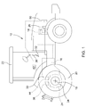
- the FIG. 1 shows an agricultural work vehicle 10 in the form of a tractor.
- the work vehicle 10 includes a traction drive train 12 consisting of a drive motor 14, a variable displacement transmission 16 and a drive axle 18 with drive wheels 20.
- the transmission may be a continuously variable transmission, a parallel shift transmission, a planetary gear transmission or an automated manual transmission.
- the working vehicle 10 has a service brake device 30 which has an actuating device 32, for example in the form of a brake pedal, arranged in a cabin 22 in the access area of an operator who is there a brake unit 34 for applying a braking torque to the drive axle 18, which transmits the braking torque to the currently traveled ground surface when actuated.
- the actuator 32 may additionally or alternatively comprise a drive lever or a hand throttle lever.
- the brake unit 34 may be designed, for example, as a wet-running multi-disc brake. Furthermore, the brake unit 34 may be arranged in a differential housing 24 and thus act on the drive axle 18.
- An operation of the service brake device 30 can be done in a conventional manner, namely by the operator operates the actuator 32 in the form of a brake pedal and provided by a hydraulic pump of the work vehicle 10 pressure oil with a brake pressure of the brake unit 34 is available.
- the position of the brake pedal 32 assumed upon actuation of the service brake device 30 can be detected by a position sensor 36, the generated brake pressure can be detected by a pressure sensor 38 and the generated braking deceleration of the work vehicle 10 can be detected by an acceleration sensor 40.
- an electronic control unit 42 is provided, which is in a data exchange and control connection with the drive motor 14, the transmission device 16, the first service brake device 30 and the sensors 36, 38, 40.
- the electronic control unit 42 may calculate one or more microcontroller 42 1, 42 comprise 2, wherein at least one microcontroller from the values of the brake pedal 32, generated brake pressure generated deceleration of work vehicle 10, a braking delay characterizing delay amount a to the work vehicle 10.
- the work vehicle 10 comprises an auxiliary brake device 50, which is designed as a retarder in a first embodiment of the work vehicle 10, to which the method according to the invention for actuating a brake system is applicable.
- the retarder can operate according to a hydrostatic operating principle and be arranged in a front region on the drive motor 14 and driven by a crankshaft 26 of the drive motor 14.
- An actuation of the auxiliary brake device 50 can be achieved by separate operating means arranged in the cabin 22 take place, which are not shown in the present case.
- an actuation of the auxiliary brake device 50 can be effected by the actuating device 32 already described in connection with the service brake device 30.
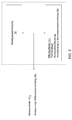
- the FIG. 2 shows schematically in a block diagram the interaction of individual required for carrying out the method according to the invention components.
- the actuator 32 is listed, by means of which a deceleration of the working vehicle 10 can be commanded.
- the actuator 32 is in control communication with the microcontroller 42 1 , which is part of the electronic control unit 42.
- driving strategies are deposited, in which, for example, transmission shift strategies are stored.
- the microcontroller 42 1 takes over the control of subsystems, for example the control of a front wheel drive which can be engaged as required, or the control of the transmission 16 as a function of a shift strategy.
- a microcontroller 42 2 is connected in terms of control.
- the inventive method may further extend to the fact that the transmission 16 is adjusted in the direction of a larger translation by means of a transmission lever, wherein the transmission lever may be encompassed by the actuator 32.
- the adjusted larger ratio of the transmission 16 provides additional braking power from the auxiliary brake system 50.
- the corresponding transmission variables such as speed or current ratio and other conditions are checked by the microcontroller 42 1 .
- the inventive method can also be used for a speed control of the drive motor 14.
- the auxiliary brake device 50 is driven in overrun mode. This can be an overspeed protection by automatically controlling the auxiliary brake device 50 when exceeding a speed limit while simultaneously falling below a torque limit.
Applications Claiming Priority (1)
| Application Number | Priority Date | Filing Date | Title |
|---|---|---|---|
| DE102015209774.9A DE102015209774A1 (de) | 2015-05-28 | 2015-05-28 | Verfahren zur Ansteuerung eines Bremssystems |
Publications (1)
| Publication Number | Publication Date |
|---|---|
| EP3098128A1 true EP3098128A1 (fr) | 2016-11-30 |
Family
ID=55970912
Family Applications (1)
| Application Number | Title | Priority Date | Filing Date |
|---|---|---|---|
| EP16169706.5A Withdrawn EP3098128A1 (fr) | 2015-05-28 | 2016-05-13 | Procede de commande d'un systeme de freinage |
Country Status (3)
| Country | Link |
|---|---|
| US (1) | US10207689B2 (fr) |
| EP (1) | EP3098128A1 (fr) |
| DE (1) | DE102015209774A1 (fr) |
Families Citing this family (2)
| Publication number | Priority date | Publication date | Assignee | Title |
|---|---|---|---|---|
| US11572066B2 (en) | 2020-12-16 | 2023-02-07 | Cnh Industrial America Llc | Self-contained intelligent braking subsystem |
| US11299141B1 (en) * | 2021-02-10 | 2022-04-12 | Deere & Company | System for multi-layer braking and retardation in a work vehicle |
Citations (5)
| Publication number | Priority date | Publication date | Assignee | Title |
|---|---|---|---|---|
| DE19822859A1 (de) * | 1998-05-22 | 1999-07-01 | Daimler Chrysler Ag | Verfahren und Vorrichtung zum Abbremsen eines Fahrzeugs |
| WO2004048172A1 (fr) * | 2002-11-26 | 2004-06-10 | Volvo Lastvagnar Ab | Procede et dispositif de repartition du couple de freinage sur un vehicule |
| EP1860008A2 (fr) * | 2006-05-26 | 2007-11-28 | WABCO GmbH | Procédé de freinage d'un véhicule |
| WO2007139489A1 (fr) * | 2006-05-26 | 2007-12-06 | Scania Cv Ab (Publ) | Système et procédé de commande de freinage d'un véhicule automobile lors de la conduite en descente |
| JP2011219015A (ja) * | 2010-04-13 | 2011-11-04 | Hino Motors Ltd | 制動制御装置、車両、および制動制御方法 |
Family Cites Families (4)
| Publication number | Priority date | Publication date | Assignee | Title |
|---|---|---|---|---|
| GB9206344D0 (en) * | 1992-03-24 | 1992-05-06 | Lucas Ind Plc | Improved braking in electronic braking systems |
| DE19741510A1 (de) * | 1996-09-20 | 1998-05-14 | Michael Meyerle | Stufenloses Getriebe, insbesondere mit hydrostatischer Leistungsverzweigung |
| DE19706451A1 (de) * | 1997-02-19 | 1998-08-20 | Man Nutzfahrzeuge Ag | Fahrzeugbremse eines Nutzfahrzeuges |
| US7670259B2 (en) * | 2007-01-05 | 2010-03-02 | Gm Global Technology Operations, Inc. | Automatic braking system |
-
2015
- 2015-05-28 DE DE102015209774.9A patent/DE102015209774A1/de active Pending
-
2016
- 2016-05-13 EP EP16169706.5A patent/EP3098128A1/fr not_active Withdrawn
- 2016-05-24 US US15/162,797 patent/US10207689B2/en active Active
Patent Citations (5)
| Publication number | Priority date | Publication date | Assignee | Title |
|---|---|---|---|---|
| DE19822859A1 (de) * | 1998-05-22 | 1999-07-01 | Daimler Chrysler Ag | Verfahren und Vorrichtung zum Abbremsen eines Fahrzeugs |
| WO2004048172A1 (fr) * | 2002-11-26 | 2004-06-10 | Volvo Lastvagnar Ab | Procede et dispositif de repartition du couple de freinage sur un vehicule |
| EP1860008A2 (fr) * | 2006-05-26 | 2007-11-28 | WABCO GmbH | Procédé de freinage d'un véhicule |
| WO2007139489A1 (fr) * | 2006-05-26 | 2007-12-06 | Scania Cv Ab (Publ) | Système et procédé de commande de freinage d'un véhicule automobile lors de la conduite en descente |
| JP2011219015A (ja) * | 2010-04-13 | 2011-11-04 | Hino Motors Ltd | 制動制御装置、車両、および制動制御方法 |
Also Published As
| Publication number | Publication date |
|---|---|
| US20160347296A1 (en) | 2016-12-01 |
| US10207689B2 (en) | 2019-02-19 |
| DE102015209774A1 (de) | 2016-12-01 |
Similar Documents
| Publication | Publication Date | Title |
|---|---|---|
| DE102014224337B4 (de) | Verfahren zur Steuerung eines hydrostatischen Antriebs | |
| WO2015043715A1 (fr) | Engin de travail automoteur et procédé de freinage d'un tel engin de travail | |
| DE102010015425A1 (de) | Vorrichtung zum Betreiben einer Antriebseinheit eines Kraftfahrzeugs | |
| DE102019203730A1 (de) | Verfahren zum Betreiben eines Antriebsstrangs für eine Arbeitsmaschine, Antriebsstrang für eine Arbeitsmaschine und Arbeitsmaschine | |
| DE102019208422A1 (de) | Verbessertes Bremsverfahren und -vorrichtung für Hybridmaschinen | |
| DE19643086C5 (de) | Retarderbremsmomentenanpassung beim Kuppeln und Schalten | |
| DE112015004086T5 (de) | Steuersysteme für hydraulisch betätigte getriebe von elektrofahrzeugen | |
| EP3381774B1 (fr) | Véhicule automobile avec un dispositif de freinage permanent | |
| DE19955313C2 (de) | Antriebssystem für Flurförderzeuge | |
| WO2020187905A1 (fr) | Procédé permettant de faire fonctionner une chaîne cinématique d'une machine de travail, chaîne cinématique pour une machine de travail et machine de travail | |
| DE112009004351T5 (de) | Bremsschmiervorrichtung und Verfahren zu deren Steuerung | |
| EP3098128A1 (fr) | Procede de commande d'un systeme de freinage | |
| DE102019215124A1 (de) | Löschfahrzeugantriebsstrang sowie Löschfahrzeug | |
| EP3298305B1 (fr) | Chaîne cinématique pour véhicules automobiles et procédé de commande | |
| DE102019214412A1 (de) | Verfahren zum Betreiben eines Antriebsstrangs für eine Arbeitsmaschine, Antriebsstrang für eine Arbeitsmaschine und Arbeitsmaschine | |
| WO2011147616A1 (fr) | Procédé pour faire fonctionner une chaîne cinématique | |
| DE112013001420T5 (de) | Steuersystem mit Antriebsstrangverriegelung | |
| DE10303415A1 (de) | Verfahren zur Optimierung des Fahrverhaltens | |
| DE102017122772A1 (de) | Steuersystem einer hydraulisch betätigten Bremseinrichtung | |
| DE102007017175B4 (de) | Verfahren zum Steuern und/oder Regeln einer Kupplung eines hydrodynamischen Lastschaltgetriebes | |
| DE102012020821B4 (de) | Notantrieb für ein Baugerät und Verfahren zum Betrieb des Notantriebs | |
| CH706518A1 (de) | Steuerung für das Antriebssystem einer Arbeitsmaschine. | |
| DE102011055177B4 (de) | Hydrostatischer Fahrantrieb für eine allradgetriebene Arbeitsmaschine | |
| DE102015015760A1 (de) | Herunterschaltmanagement bei hoher drehzahl | |
| DE102019203735A1 (de) | Antriebsstrang für eine Arbeitsmaschine und Arbeitsmaschine |
Legal Events
| Date | Code | Title | Description |
|---|---|---|---|
| PUAI | Public reference made under article 153(3) epc to a published international application that has entered the european phase |
Free format text: ORIGINAL CODE: 0009012 |
|
| AK | Designated contracting states |
Kind code of ref document: A1 Designated state(s): AL AT BE BG CH CY CZ DE DK EE ES FI FR GB GR HR HU IE IS IT LI LT LU LV MC MK MT NL NO PL PT RO RS SE SI SK SM TR |
|
| AX | Request for extension of the european patent |
Extension state: BA ME |
|
| 17P | Request for examination filed |
Effective date: 20170530 |
|
| RBV | Designated contracting states (corrected) |
Designated state(s): AL AT BE BG CH CY CZ DE DK EE ES FI FR GB GR HR HU IE IS IT LI LT LU LV MC MK MT NL NO PL PT RO RS SE SI SK SM TR |
|
| STAA | Information on the status of an ep patent application or granted ep patent |
Free format text: STATUS: THE APPLICATION IS DEEMED TO BE WITHDRAWN |
|
| 18D | Application deemed to be withdrawn |
Effective date: 20170531 |