EP3098128A1 - Method for actuating a braking system - Google Patents
Method for actuating a braking system Download PDFInfo
- Publication number
- EP3098128A1 EP3098128A1 EP16169706.5A EP16169706A EP3098128A1 EP 3098128 A1 EP3098128 A1 EP 3098128A1 EP 16169706 A EP16169706 A EP 16169706A EP 3098128 A1 EP3098128 A1 EP 3098128A1
- Authority
- EP
- European Patent Office
- Prior art keywords
- brake device
- drive
- brake
- auxiliary
- drive motor
- Prior art date
- Legal status (The legal status is an assumption and is not a legal conclusion. Google has not performed a legal analysis and makes no representation as to the accuracy of the status listed.)
- Withdrawn
Links
Images
Classifications
-
- B—PERFORMING OPERATIONS; TRANSPORTING
- B60—VEHICLES IN GENERAL
- B60T—VEHICLE BRAKE CONTROL SYSTEMS OR PARTS THEREOF; BRAKE CONTROL SYSTEMS OR PARTS THEREOF, IN GENERAL; ARRANGEMENT OF BRAKING ELEMENTS ON VEHICLES IN GENERAL; PORTABLE DEVICES FOR PREVENTING UNWANTED MOVEMENT OF VEHICLES; VEHICLE MODIFICATIONS TO FACILITATE COOLING OF BRAKES
- B60T8/00—Arrangements for adjusting wheel-braking force to meet varying vehicular or ground-surface conditions, e.g. limiting or varying distribution of braking force
- B60T8/32—Arrangements for adjusting wheel-braking force to meet varying vehicular or ground-surface conditions, e.g. limiting or varying distribution of braking force responsive to a speed condition, e.g. acceleration or deceleration
- B60T8/321—Arrangements for adjusting wheel-braking force to meet varying vehicular or ground-surface conditions, e.g. limiting or varying distribution of braking force responsive to a speed condition, e.g. acceleration or deceleration deceleration
- B60T8/3215—Systems characterised by having means acting on components of the drive line, e.g. retarder, clutch or differential gear
-
- B—PERFORMING OPERATIONS; TRANSPORTING
- B60—VEHICLES IN GENERAL
- B60T—VEHICLE BRAKE CONTROL SYSTEMS OR PARTS THEREOF; BRAKE CONTROL SYSTEMS OR PARTS THEREOF, IN GENERAL; ARRANGEMENT OF BRAKING ELEMENTS ON VEHICLES IN GENERAL; PORTABLE DEVICES FOR PREVENTING UNWANTED MOVEMENT OF VEHICLES; VEHICLE MODIFICATIONS TO FACILITATE COOLING OF BRAKES
- B60T10/00—Control or regulation for continuous braking making use of fluid or powdered medium, e.g. for use when descending a long slope
- B60T10/04—Control or regulation for continuous braking making use of fluid or powdered medium, e.g. for use when descending a long slope with hydrostatic brake
-
- A—HUMAN NECESSITIES
- A01—AGRICULTURE; FORESTRY; ANIMAL HUSBANDRY; HUNTING; TRAPPING; FISHING
- A01B—SOIL WORKING IN AGRICULTURE OR FORESTRY; PARTS, DETAILS, OR ACCESSORIES OF AGRICULTURAL MACHINES OR IMPLEMENTS, IN GENERAL
- A01B76/00—Parts, details or accessories of agricultural machines or implements, not provided for in groups A01B51/00 - A01B75/00
-
- B—PERFORMING OPERATIONS; TRANSPORTING
- B60—VEHICLES IN GENERAL
- B60T—VEHICLE BRAKE CONTROL SYSTEMS OR PARTS THEREOF; BRAKE CONTROL SYSTEMS OR PARTS THEREOF, IN GENERAL; ARRANGEMENT OF BRAKING ELEMENTS ON VEHICLES IN GENERAL; PORTABLE DEVICES FOR PREVENTING UNWANTED MOVEMENT OF VEHICLES; VEHICLE MODIFICATIONS TO FACILITATE COOLING OF BRAKES
- B60T13/00—Transmitting braking action from initiating means to ultimate brake actuator with power assistance or drive; Brake systems incorporating such transmitting means, e.g. air-pressure brake systems
- B60T13/10—Transmitting braking action from initiating means to ultimate brake actuator with power assistance or drive; Brake systems incorporating such transmitting means, e.g. air-pressure brake systems with fluid assistance, drive, or release
- B60T13/58—Combined or convertible systems
- B60T13/585—Combined or convertible systems comprising friction brakes and retarders
-
- B—PERFORMING OPERATIONS; TRANSPORTING
- B60—VEHICLES IN GENERAL
- B60T—VEHICLE BRAKE CONTROL SYSTEMS OR PARTS THEREOF; BRAKE CONTROL SYSTEMS OR PARTS THEREOF, IN GENERAL; ARRANGEMENT OF BRAKING ELEMENTS ON VEHICLES IN GENERAL; PORTABLE DEVICES FOR PREVENTING UNWANTED MOVEMENT OF VEHICLES; VEHICLE MODIFICATIONS TO FACILITATE COOLING OF BRAKES
- B60T13/00—Transmitting braking action from initiating means to ultimate brake actuator with power assistance or drive; Brake systems incorporating such transmitting means, e.g. air-pressure brake systems
- B60T13/10—Transmitting braking action from initiating means to ultimate brake actuator with power assistance or drive; Brake systems incorporating such transmitting means, e.g. air-pressure brake systems with fluid assistance, drive, or release
- B60T13/66—Electrical control in fluid-pressure brake systems
- B60T13/662—Electrical control in fluid-pressure brake systems characterised by specified functions of the control system components
Definitions
- the invention relates to a method for controlling a brake system in an agricultural work vehicle, the work vehicle having a drive train with a drive motor, a drive of the downstream drive with adjustable ratio, via which a drive power generated by the engine is transferable to a drive axle, a service brake device and at least an auxiliary brake device comprises.
- the service brake device Due to the principle of the service brake device of an agricultural work vehicle is subject to wear. Regularly, the service brake device is designed as a hydraulically operated and oil-cooled disc brake whose lamellar friction linings are arranged within the transmission or differential housing. This results in oil cooling via the transmission oil, which in turn can be part of the hydraulic oil circuit.
- the disadvantage of this integrated in the gearbox or differential housing service brake device is the maintenance challenge in the case in which an exchange of friction linings must be done. This can usually only be done by removing the gearbox or differential.
- the object is achieved by a method for controlling a brake system in an agricultural work vehicle, wherein the work vehicle a drive train with a drive motor, a drive motor downstream transmission with adjustable ratio, via which a drive power generated by the drive motor is transferable to a drive axle, a service brake device and at least one auxiliary brake device and an actuating device, to means of a braking delay characterizing delay amount a of the work vehicle to the service brake device and the auxiliary brake device can be commanded at least, said at least one auxiliary brake device is as long as priority driven with respect to the service brake device across the actuator as long as the from the at least one auxiliary brake device provided delay amount a aux the commanded delays approximately a size capable to cover and an activation of the service brake device takes place only when the commanded deceleration variable a to the maximum achievable by the at least one auxiliary brake device delay amount exceeds a aux.
- the method according to the invention provides an integrated regulation of the service brake device and of the at least one auxiliary brake device in order to achieve efficient use of the systems in combination. Furthermore, the method according to the invention provides a modular approach for controlling at least one auxiliary braking system with a variable degree of complexity, including its implementation in an overall vehicle control system.
- the actuating device preferably comprises activatable operating means by an operator of the work vehicle.
- the control means are designed in a simplest embodiment as an additionally installed control lever, for example as a separate auxiliary brake lever or as an activation / deactivation switch for an auxiliary brake system.
- the operating means by existing controls of the working vehicle, for example a brake pedal or a driving lever.
- the at least one auxiliary brake power system preferably imposes its braking power on a crankshaft of the drive motor. This ensures that the braking power are transmitted via the drive motor and the subsequent transmission on drive wheels of the work vehicle in any case.
- auxiliary brake systems Preferably, at least during one of the auxiliary brake systems, priority is given to adjusting a transmission ratio in the direction of a greater ratio. This is to be understood by a larger translation that at a constant speed or speed of the drive wheels, a higher speed of the drive motor is applied.
- the work vehicle comprises an electronic control device, wherein the electronic control device controls the at least one auxiliary power brake system when exceeding a speed limit of the drive motor while falling short of a torque limit of the drive motor. This makes it easy to represent an overload speed protection for the drive motor.
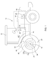
- the FIG. 1 shows an agricultural work vehicle 10 in the form of a tractor.
- the work vehicle 10 includes a traction drive train 12 consisting of a drive motor 14, a variable displacement transmission 16 and a drive axle 18 with drive wheels 20.
- the transmission may be a continuously variable transmission, a parallel shift transmission, a planetary gear transmission or an automated manual transmission.
- the working vehicle 10 has a service brake device 30 which has an actuating device 32, for example in the form of a brake pedal, arranged in a cabin 22 in the access area of an operator who is there a brake unit 34 for applying a braking torque to the drive axle 18, which transmits the braking torque to the currently traveled ground surface when actuated.
- the actuator 32 may additionally or alternatively comprise a drive lever or a hand throttle lever.
- the brake unit 34 may be designed, for example, as a wet-running multi-disc brake. Furthermore, the brake unit 34 may be arranged in a differential housing 24 and thus act on the drive axle 18.
- An operation of the service brake device 30 can be done in a conventional manner, namely by the operator operates the actuator 32 in the form of a brake pedal and provided by a hydraulic pump of the work vehicle 10 pressure oil with a brake pressure of the brake unit 34 is available.
- the position of the brake pedal 32 assumed upon actuation of the service brake device 30 can be detected by a position sensor 36, the generated brake pressure can be detected by a pressure sensor 38 and the generated braking deceleration of the work vehicle 10 can be detected by an acceleration sensor 40.
- an electronic control unit 42 is provided, which is in a data exchange and control connection with the drive motor 14, the transmission device 16, the first service brake device 30 and the sensors 36, 38, 40.
- the electronic control unit 42 may calculate one or more microcontroller 42 1, 42 comprise 2, wherein at least one microcontroller from the values of the brake pedal 32, generated brake pressure generated deceleration of work vehicle 10, a braking delay characterizing delay amount a to the work vehicle 10.
- the work vehicle 10 comprises an auxiliary brake device 50, which is designed as a retarder in a first embodiment of the work vehicle 10, to which the method according to the invention for actuating a brake system is applicable.
- the retarder can operate according to a hydrostatic operating principle and be arranged in a front region on the drive motor 14 and driven by a crankshaft 26 of the drive motor 14.
- An actuation of the auxiliary brake device 50 can be achieved by separate operating means arranged in the cabin 22 take place, which are not shown in the present case.
- an actuation of the auxiliary brake device 50 can be effected by the actuating device 32 already described in connection with the service brake device 30.
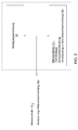
- the FIG. 2 shows schematically in a block diagram the interaction of individual required for carrying out the method according to the invention components.
- the actuator 32 is listed, by means of which a deceleration of the working vehicle 10 can be commanded.
- the actuator 32 is in control communication with the microcontroller 42 1 , which is part of the electronic control unit 42.
- driving strategies are deposited, in which, for example, transmission shift strategies are stored.
- the microcontroller 42 1 takes over the control of subsystems, for example the control of a front wheel drive which can be engaged as required, or the control of the transmission 16 as a function of a shift strategy.
- a microcontroller 42 2 is connected in terms of control.
- the inventive method may further extend to the fact that the transmission 16 is adjusted in the direction of a larger translation by means of a transmission lever, wherein the transmission lever may be encompassed by the actuator 32.
- the adjusted larger ratio of the transmission 16 provides additional braking power from the auxiliary brake system 50.
- the corresponding transmission variables such as speed or current ratio and other conditions are checked by the microcontroller 42 1 .
- the inventive method can also be used for a speed control of the drive motor 14.
- the auxiliary brake device 50 is driven in overrun mode. This can be an overspeed protection by automatically controlling the auxiliary brake device 50 when exceeding a speed limit while simultaneously falling below a torque limit.
Abstract
Die Erfindung betrifft ein Verfahren zur Ansteuerung eines Bremssystems in einem landwirtschaftlichen Arbeitsfahrzeug, wobei das Arbeitsfahrzeug einen Antriebsstrang mit einem Antriebsmotor, ein dem Antriebsmotor nachgeschaltetes Getriebe mit verstellbarer Übersetzung, über das eine von dem Verbrennungsmotor erzeugte Antriebsleistung auf eine Antriebsachse übertragbar ist, eine Betriebsbremseinrichtung und zumindest eine Hilfsbremseinrichtung umfasst.The invention relates to a method for controlling a brake system in an agricultural work vehicle, the work vehicle having a drive train with a drive motor, a drive of the downstream drive with adjustable ratio, via which a drive power generated by the engine is transferable to a drive axle, a service brake device and at least an auxiliary brake device comprises.
Description
Die Erfindung betrifft ein Verfahren zur Ansteuerung eines Bremssystems in einem landwirtschaftlichen Arbeitsfahrzeug, wobei das Arbeitsfahrzeug einen Antriebsstrang mit einem Antriebsmotor, ein dem Antriebsmotor nachgeschaltetes Getriebe mit verstellbarer Übersetzung, über das eine von dem Verbrennungsmotor erzeugte Antriebsleistung auf eine Antriebsachse übertragbar ist, eine Betriebsbremseinrichtung und zumindest eine Hilfsbremseinrichtung umfasst.The invention relates to a method for controlling a brake system in an agricultural work vehicle, the work vehicle having a drive train with a drive motor, a drive of the downstream drive with adjustable ratio, via which a drive power generated by the engine is transferable to a drive axle, a service brake device and at least an auxiliary brake device comprises.
Prinzipbedingt ist die Betriebsbremseinrichtung eines landwirtschaftlichen Arbeitsfahrzeugs verschleißbehaftet. Regelmäßig ist die Betriebsbremseinrichtung als hydraulisch betätigte und ölgekühlte Scheibenbremse ausgeführt, deren lamellenartig angeordnete Reibbeläge innerhalb des Getriebe- oder Differentialgehäuse angeordnet sind. Hierdurch erfolgt eine Ölkühlung über das Getriebeöl, welches seinerseits Teil des Hydraulikölkreislaufs sein kann. Der Nachteil dieser in das Getriebe- oder Differentialgehäuse integrierten Betriebsbremseinrichtung besteht in der wartungstechnischen Herausforderung in dem Fall, in dem ein Austausch der Reibbeläge erfolgen muss. Dies kann in der Regel nur über einen Ausbau des Getriebes oder Differentials erfolgen.Due to the principle of the service brake device of an agricultural work vehicle is subject to wear. Regularly, the service brake device is designed as a hydraulically operated and oil-cooled disc brake whose lamellar friction linings are arranged within the transmission or differential housing. This results in oil cooling via the transmission oil, which in turn can be part of the hydraulic oil circuit. The disadvantage of this integrated in the gearbox or differential housing service brake device is the maintenance challenge in the case in which an exchange of friction linings must be done. This can usually only be done by removing the gearbox or differential.
Zur Reduktion von reparatur- und wartungsbedingten Stillstandzeiten von landwirtschaftlichen Arbeitsfahrzeugen ist es notwendig, wartungsintensive Komponenten wie eine Betriebsbremseinrichtung durch zumindest wartungsarme Komponenten zu entlasten oder zu ersetzen. Ein Entlasten hätte zumindest den Vorteil, dass das Wartungsintervall der wartungsintensiven Komponente verlängert wird.To reduce repair and maintenance-related downtime of agricultural work vehicles, it is necessary to relieve or replace maintenance-intensive components such as a service brake device by at least low-maintenance components. Relieving would at least have the advantage that the maintenance interval of the maintenance-intensive component is extended.
Bekannt sind im Stand der Technik Hilfsbremseinrichtung, die nach verschiedenen physikalischen Wirkprinzipien arbeiten. Zu nennen sind hier eine variable Turbinengeometrie bei einem Abgasturbolader, ein hydrostatischer Retarder, eine Wirbelstrombremse, eine Abgasbremse, eine Hydrauliksystembremse oder eine generatorisch betriebene elektrische Antriebsachse. Die zusätzliche Verfügbarkeit einer Hilfsbremseinrichtung kann die Lebensdauer beziehungsweise das Wartungsintervall der Betriebsbremseinrichtung der Arbeitsmaschine signifikant verlängern, da deren Einsatz, sowohl bezüglich der Dauer als auch der Häufigkeit, nämlich insbesondere im verschleißfördernden Transportgeschwindigkeitsbereich reduziert wird.In the prior art, auxiliary brake devices which operate according to various physical principles of action are known. Worth mentioning here are a variable turbine geometry in an exhaust gas turbocharger, a hydrostatic retarder, an eddy current brake, an exhaust brake, a hydraulic system brake or a regeneratively operated electric drive axle. The additional availability of an auxiliary brake device can significantly extend the service life or the maintenance interval of the service brake device of the work machine since its use is reduced, both with respect to duration and frequency, namely in the wear-promoting transport speed range.
Ausgehend hiervon besteht die Aufgabe der vorliegenden Erfindung darin, ein Verfahren bereitzustellen, das den Einsatz einer Betriebsbremseinrichtung und zumindest einer Hilfsbremseinrichtung derart aufeinander abstimmt, dass die Lebensdauer der Betriebsbremseinrichtung erhöht wird.Proceeding from this, the object of the present invention is to provide a method which tunes the use of a service brake device and at least one auxiliary brake device to one another such that the service life of the service brake device is increased.
Die Aufgabe wird gelöst durch ein Verfahren zur Ansteuerung eines Bremssystems in einem landwirtschaftlichen Arbeitsfahrzeug, wobei das Arbeitsfahrzeug einen Antriebsstrang mit einem Antriebsmotor, ein dem Antriebsmotor nachgeschaltetes Getriebe mit verstellbarer Übersetzung, über das eine von dem Antriebsmotor erzeugte Antriebsleistung auf eine Antriebsachse übertragbar ist, eine Betriebsbremseinrichtung und zumindest eine Hilfsbremseinrichtung und eine Betätigungseinrichtung, mittels der eine eine Bremsverzögerung charakterisierende Verzögerungsgröße asoll des Arbeitsfahrzeugs auf die Betriebsbremseinrichtung und die zumindest eine Hilfsbremseinrichtung kommandiert werden kann, umfasst wobei über die Betätigungseinrichtung die zumindest eine Hilfsbremseinrichtung solange prioritär gegenüber der Betriebsbremseinrichtung angesteuert wird, solange die von der zumindest einen Hilfsbremseinrichtung zur Verfügung gestellte Verzögerungsgröße aaux die kommandierte Verzögerungsgröße asoll zu decken vermag und eine Ansteuerung der Betriebsbremseinrichtung erst erfolgt, wenn die kommandierte Verzögerungsgröße asoll die maximale durch die zumindest eine Hilfsbremseinrichtung erreichbare Verzögerungsgröße aaux übersteigt.The object is achieved by a method for controlling a brake system in an agricultural work vehicle, wherein the work vehicle a drive train with a drive motor, a drive motor downstream transmission with adjustable ratio, via which a drive power generated by the drive motor is transferable to a drive axle, a service brake device and at least one auxiliary brake device and an actuating device, to means of a braking delay characterizing delay amount a of the work vehicle to the service brake device and the auxiliary brake device can be commanded at least, said at least one auxiliary brake device is as long as priority driven with respect to the service brake device across the actuator as long as the from the at least one auxiliary brake device provided delay amount a aux the commanded delays approximately a size capable to cover and an activation of the service brake device takes place only when the commanded deceleration variable a to the maximum achievable by the at least one auxiliary brake device delay amount exceeds a aux.
Durch das erfindungsgemäße Verfahren wird eine integrierte Regelung der Betriebsbremseinrichtung und der zumindest einen Hilfsbremseinrichtung bereitgestellt, um eine effiziente Anwendung der Systeme im Verbund zu erreichen. Weiterhin wird durch das erfindungsgemäße Verfahren ein modular aufgebauter Ansatz zur Regelung zumindest eines Hilfsbremssystems mit variablem Komplexitätsgrades bereitgestellt, einschließlich dessen Implementierung in eine Gesamtfahrzeugsteuerung.The method according to the invention provides an integrated regulation of the service brake device and of the at least one auxiliary brake device in order to achieve efficient use of the systems in combination. Furthermore, the method according to the invention provides a modular approach for controlling at least one auxiliary braking system with a variable degree of complexity, including its implementation in an overall vehicle control system.
Bevorzugt umfasst die Betätigungseinrichtung durch eine Bedienperson des Arbeitsfahrzeugs aktivierbare Bedienmittel. Hierbei sind die Bedienmittel in einer einfachsten Ausgestaltung als zusätzlich installierter Bedienhebel ausgeführt, beispielsweise als separater Hilfsbremshebel oder als Aktivierung-/Deaktivierungsschalter für ein Hilfsbremssystem. In einer weiteren Ausgestaltung werden die Bedienmittel durch bestehende Bedienelemente des Arbeitsfahrzeugs gebildet, beispielsweise ein Bremspedal oder einen Fahrhebel.The actuating device preferably comprises activatable operating means by an operator of the work vehicle. Here, the control means are designed in a simplest embodiment as an additionally installed control lever, for example as a separate auxiliary brake lever or as an activation / deactivation switch for an auxiliary brake system. In a further embodiment, the operating means by existing controls of the working vehicle, for example a brake pedal or a driving lever.
Bevorzugt prägt das zumindest eine Hilfsbremskraftsystem seine Bremsleistung einer Kurbelwelle des Antriebsmotors auf. Hierdurch ist gewährleistet, dass die Bremsleistung jedenfalls über den Antriebsmotor und das sich anschließende Getriebe auf Antriebsräder des Arbeitsfahrzeugs übertragen werden.The at least one auxiliary brake power system preferably imposes its braking power on a crankshaft of the drive motor. This ensures that the braking power are transmitted via the drive motor and the subsequent transmission on drive wheels of the work vehicle in any case.
Bevorzugt wird, zumindest während eines der Hilfsbremssysteme prioritär angesteuert wird, eine Übersetzung des Getriebes in Richtung einer größeren Übersetzung verstellt. Hierbei ist unter größerer Übersetzung zu verstehen, dass bei gleichbleibender Drehzahl bzw. Geschwindigkeit der Antriebsräder eine höhere Drehzahl des Antriebsmotors anliegt.Preferably, at least during one of the auxiliary brake systems, priority is given to adjusting a transmission ratio in the direction of a greater ratio. This is to be understood by a larger translation that at a constant speed or speed of the drive wheels, a higher speed of the drive motor is applied.
Bevorzugt umfasst das Arbeitsfahrzeug eine elektronische Steuereinrichtung, wobei die elektronische Steuereinrichtung das zumindest eine Hilfskraftbremssystem bei Überschreitung einer Drehzahlgrenze des Antriebsmotors bei gleichzeitiger Unterschreitung einer Drehmomentgrenze des Antriebsmotors ansteuert. Hierdurch lässt sich in einfacher Weise ein Überlast Drehzahlschutz für den Antriebsmotor darstellen.Preferably, the work vehicle comprises an electronic control device, wherein the electronic control device controls the at least one auxiliary power brake system when exceeding a speed limit of the drive motor while falling short of a torque limit of the drive motor. This makes it easy to represent an overload speed protection for the drive motor.
Das erfindungsgemäße Verfahren wird anhand der nachfolgenden Figuren erläutern. Hierin zeigen
Figur 1- ein landwirtschaftliches Arbeitsfahrzeug und
Figur 2- ein Blockdiagramm von Komponenten zur Ausführung des erfindungsgemäßen Verfahrens.
- FIG. 1
- an agricultural work vehicle and
- FIG. 2
- a block diagram of components for carrying out the method according to the invention.
Die
Eine Betätigung der Betriebsbremseinrichtung 30 kann in herkömmlicher Weise erfolgen, nämlich indem die Bedienperson die Betätigungseinrichtung 32 in Form eines Bremspedals betätigt und von einer Hydraulikpumpe des Arbeitsfahrzeugs 10 bereitgestelltes Drucköl mit einem Bremsdruck der Bremseinheit 34 zur Verfügung steht. Die bei Betätigung der Betriebsbremseinrichtung 30 eingenommene Stellung des Bremspedals 32 kann mit einem Positionssensor 36, der erzeugte Bremsdruck kann mit einem Drucksensor 38 und die erzeugte Bremsverzögerung des Arbeitsfahrzeugs 10 kann mit einem Beschleunigungssensor 40 erfasst werden. Ferner ist eine elektronische Kontrolleinheit 42 vorgesehen, die mit der Antriebsmotor 14, der Getriebevorrichtung 16, der ersten Betriebsbremseinrichtung 30 und den Sensoren 36, 38, 40 in einer Datenaustausch- und Steuerungsverbindung steht.An operation of the
Die elektronische Kontrolleinheit 42 kann einen oder mehrere Mikrokontroller 421, 422 umfassen, wobei zumindest ein Mikrokontroller aus den Werten Stellung des Bremspedals 32, erzeugter Bremsdruck und erzeugte Bremsverzögerung des Arbeitsfahrzeugs 10 eine eine Bremsverzögerung charakterisierende Verzögerungsgröße asoll des Arbeitsfahrzeugs 10 errechnet.The
Ferner zeigt die
Die
Das erfindungsgemäße Verfahren kann sich weiterhin darauf erstrecken, dass das Getriebe 16 in Richtung einer größeren Übersetzung mittels eines Übersetzungshebels verstellt wird, wobei der Übersetzungshebel von der Betätigungseinrichtung 32 umfasst sein kann. Durch die eingestellte größere Übersetzung des Getriebes 16 wird zusätzliche Bremsleistung von dem Hilfsbremssystem 50 bereitgestellt. Hierzu werden durch den Mikrokontroller 421 die entsprechenden Getriebevariablen wie Drehzahl oder derzeitige Übersetzung und weitere Bedingungen überprüft.The inventive method may further extend to the fact that the
Das erfindungsgemäße Verfahren kann auch für eine Drehzahlregelung des Antriebsmotors 14 genutzt werden. Hierbei wird die Hilfsbremseinrichtung 50 im Schubbetrieb angesteuert. Hierdurch lässt sich ein Überdrehzahlschutz durch automatisches Ansteuern der Hilfsbremseinrichtung 50 bei Überschreitung einer Drehzahlgrenze bei gleichzeitiger Unterschreitung einer Drehmomentgrenze darstellen.The inventive method can also be used for a speed control of the
Durch ein Ansteuern der Hilfsbremseinrichtung 50 während einer Warmlaufphase des Antriebsmotors 14 kann ein schnelleres Aufheizen des Antriebsmotors 14 und einer Hydraulikanlage des Arbeitsfahrzeugs 10 erreicht, da durch die Hilfsbremseinrichtung 50 eine künstliche Last generiert wird.By activating the
Im Zusammenhang mit der
- 1010
- Arbeitsfahrzeugworking vehicle
- 1212
- Antriebsstrangpowertrain
- 1414
- Antriebsmotordrive motor
- 1616
- Getriebetransmission
- 1818
- Antriebsachsedrive axle
- 2020
- Antriebsräderdrive wheels
- 2222
- Kabinecabin
- 2424
- Differentialgehäusedifferential case
- 2626
- Kurbelwellecrankshaft
- 3030
- BetriebsbremseinrichtungService brake device
- 3232
- Betätigungseinrichtungactuator
- 3434
- Bremseinheitbrake unit
- 3636
- Positionssensorposition sensor
- 3838
- Drucksensorpressure sensor
- 4040
- Beschleunigungssensoraccelerometer
- 4242
- elektronische Kontrolleinheitelectronic control unit
- 421, 422 42 1 , 42 2
- Mikrokontrollermicrocontroller
- 5050
- HilfsbremseinrichtungAuxiliary braking device
Claims (6)
einen Antriebsstrang (12) mit einem Antriebsmotor (14),
ein dem Antriebsmotor (14) nachgeschaltetes Getriebe (16) mit verstellbarer Übersetzung, über das eine von dem Antriebsmotor (22) erzeugte Antriebsleistung auf eine Antriebsachse (18) übertragbar ist,
eine Betriebsbremseinrichtung (30) und zumindest eine Hilfsbremseinrichtung (50) und
eine Betätigungseinrichtung (32), mittels der eine eine Bremsverzögerung charakterisierende Verzögerungsgröße (asoll) des Arbeitsfahrzeugs (10) auf die Betriebsbremseinrichtung (32) und die zumindest eine Hilfsbremseinrichtung (50) kommandiert werden kann, umfasst
wobei über die Betätigungseinrichtung (32) die zumindest eine Hilfsbremseinrichtung (50) solange prioritär gegenüber der Betriebsbremseinrichtung (32) angesteuert wird, solange die von der zumindest einen Hilfsbremseinrichtung (50) zur Verfügung gestellte Verzögerungsgröße (aaux) die kommandierte Verzögerungsgröße (asoll) zu decken vermag und eine Ansteuerung der Betriebsbremseinrichtung (50) erst erfolgt, wenn die kommandierte Verzögerungsgröße (asoll) die maximale durch die zumindest eine Hilfsbremseinrichtung (50) erreichbare Verzögerungsgröße (aaux) übersteigt.Method for controlling a brake system in an agricultural work vehicle (10), wherein the work vehicle (10)
a drive train (12) with a drive motor (14),
a drive (14) downstream transmission (16) with adjustable ratio, via which a drive power generated by the drive motor (22) on a drive axle (18) is transferable,
a service brake device (30) and at least one auxiliary brake device (50) and
an actuating device (32) by means of which a deceleration variable (a soll ) of the working vehicle (10) characterizing a braking deceleration can be commanded onto the service brake device (32) and the at least one auxiliary brake device (50)
wherein via the actuating device (32) the at least one auxiliary brake device (50) is actuated with priority over the service brake device (32) as long as the delay quantity (a aux ) provided by the at least one auxiliary brake device (50) supplies the commanded delay variable (a soll ) is able to cover and a control of the service brake device (50) takes place only when the commanded delay quantity (a soll ) exceeds the maximum by the at least one auxiliary brake device (50) achievable delay quantity (a aux ).
Applications Claiming Priority (1)
| Application Number | Priority Date | Filing Date | Title |
|---|---|---|---|
| DE102015209774.9A DE102015209774A1 (en) | 2015-05-28 | 2015-05-28 | Method for controlling a brake system |
Publications (1)
| Publication Number | Publication Date |
|---|---|
| EP3098128A1 true EP3098128A1 (en) | 2016-11-30 |
Family
ID=55970912
Family Applications (1)
| Application Number | Title | Priority Date | Filing Date |
|---|---|---|---|
| EP16169706.5A Withdrawn EP3098128A1 (en) | 2015-05-28 | 2016-05-13 | Method for actuating a braking system |
Country Status (3)
| Country | Link |
|---|---|
| US (1) | US10207689B2 (en) |
| EP (1) | EP3098128A1 (en) |
| DE (1) | DE102015209774A1 (en) |
Families Citing this family (2)
| Publication number | Priority date | Publication date | Assignee | Title |
|---|---|---|---|---|
| US11572066B2 (en) | 2020-12-16 | 2023-02-07 | Cnh Industrial America Llc | Self-contained intelligent braking subsystem |
| US11299141B1 (en) * | 2021-02-10 | 2022-04-12 | Deere & Company | System for multi-layer braking and retardation in a work vehicle |
Citations (5)
| Publication number | Priority date | Publication date | Assignee | Title |
|---|---|---|---|---|
| DE19822859A1 (en) * | 1998-05-22 | 1999-07-01 | Daimler Chrysler Ag | Commercial vehicle braking system for co-ordinated braking |
| WO2004048172A1 (en) * | 2002-11-26 | 2004-06-10 | Volvo Lastvagnar Ab | Method and apparatus for the distribution of brake torque on a vehicle |
| EP1860008A2 (en) * | 2006-05-26 | 2007-11-28 | WABCO GmbH | Method for slowing down a vehicle |
| WO2007139489A1 (en) * | 2006-05-26 | 2007-12-06 | Scania Cv Ab (Publ) | A system and a method for controlling braking of a motor vehicle during downhill driving |
| JP2011219015A (en) * | 2010-04-13 | 2011-11-04 | Hino Motors Ltd | Braking control device, vehicle, and braking control method |
Family Cites Families (4)
| Publication number | Priority date | Publication date | Assignee | Title |
|---|---|---|---|---|
| GB9206344D0 (en) * | 1992-03-24 | 1992-05-06 | Lucas Ind Plc | Improved braking in electronic braking systems |
| DE19741510A1 (en) * | 1996-09-20 | 1998-05-14 | Michael Meyerle | Continuous transmission esp. with hydrostatic power branching e.g. for tractors and commercial vehicles |
| DE19706451A1 (en) * | 1997-02-19 | 1998-08-20 | Man Nutzfahrzeuge Ag | Vehicle brake of a commercial vehicle |
| US7670259B2 (en) * | 2007-01-05 | 2010-03-02 | Gm Global Technology Operations, Inc. | Automatic braking system |
-
2015
- 2015-05-28 DE DE102015209774.9A patent/DE102015209774A1/en active Pending
-
2016
- 2016-05-13 EP EP16169706.5A patent/EP3098128A1/en not_active Withdrawn
- 2016-05-24 US US15/162,797 patent/US10207689B2/en active Active
Patent Citations (5)
| Publication number | Priority date | Publication date | Assignee | Title |
|---|---|---|---|---|
| DE19822859A1 (en) * | 1998-05-22 | 1999-07-01 | Daimler Chrysler Ag | Commercial vehicle braking system for co-ordinated braking |
| WO2004048172A1 (en) * | 2002-11-26 | 2004-06-10 | Volvo Lastvagnar Ab | Method and apparatus for the distribution of brake torque on a vehicle |
| EP1860008A2 (en) * | 2006-05-26 | 2007-11-28 | WABCO GmbH | Method for slowing down a vehicle |
| WO2007139489A1 (en) * | 2006-05-26 | 2007-12-06 | Scania Cv Ab (Publ) | A system and a method for controlling braking of a motor vehicle during downhill driving |
| JP2011219015A (en) * | 2010-04-13 | 2011-11-04 | Hino Motors Ltd | Braking control device, vehicle, and braking control method |
Also Published As
| Publication number | Publication date |
|---|---|
| US20160347296A1 (en) | 2016-12-01 |
| DE102015209774A1 (en) | 2016-12-01 |
| US10207689B2 (en) | 2019-02-19 |
Similar Documents
| Publication | Publication Date | Title |
|---|---|---|
| DE102014224337B4 (en) | Method of controlling a hydrostatic drive | |
| WO2015043715A1 (en) | Self-propelled working machine and method for braking a working machine of this type | |
| DE102010015425A1 (en) | Device for operating a drive unit of a motor vehicle | |
| DE102019203730A1 (en) | Method for operating a drive train for a work machine, drive train for a work machine and work machine | |
| DE102019208422A1 (en) | Improved braking method and device for hybrid machines | |
| EP3034369A1 (en) | Mobile working machine with a braking device | |
| DE19643086C5 (en) | Retarder braking torque adaptation when coupling and shifting | |
| DE102019214412A1 (en) | Method for operating a drive train for a work machine, a drive train for a work machine and a work machine | |
| DE112015004086T5 (en) | CONTROL SYSTEMS FOR HYDRAULICALLY OPERATED GEARBOXES OF ELECTRIC VEHICLES | |
| EP3381774B1 (en) | Motor vehicle with a retarder | |
| DE19955313C2 (en) | Drive system for industrial trucks | |
| WO2020187905A1 (en) | Method for operating a drive train of a working machine, drive train for a working machine, and working machine | |
| DE112009004351T5 (en) | Brake lubrication device and method for its control | |
| EP3098128A1 (en) | Method for actuating a braking system | |
| DE102019215124A1 (en) | Fire engine drive train and fire engine | |
| EP3298305B1 (en) | Motor vehicle powertrain and actuation method | |
| DE19643079A1 (en) | Braking torque adjustment of a primary system depending on the gear position | |
| WO2011147616A1 (en) | Method for operating a drive train | |
| DE112013001420T5 (en) | Control system with powertrain interlock | |
| DE10303415A1 (en) | Procedure for optimizing driving behavior | |
| DE102017122772A1 (en) | Control system of a hydraulically operated braking device | |
| DE102007017175B4 (en) | Method for controlling and / or regulating a clutch of a hydrodynamic powershift transmission | |
| DE102012020821B4 (en) | Emergency drive for a construction device and method for operating the emergency drive | |
| CH706518A1 (en) | Control unit for drive system of work machine e.g. cable-operated excavator, sets operating point of engine to determine services and efficiency characteristic fields of components based on fuel consumption map of engine | |
| DE102011055177B4 (en) | Hydrostatic drive for an all-wheel drive machine |
Legal Events
| Date | Code | Title | Description |
|---|---|---|---|
| PUAI | Public reference made under article 153(3) epc to a published international application that has entered the european phase |
Free format text: ORIGINAL CODE: 0009012 |
|
| AK | Designated contracting states |
Kind code of ref document: A1 Designated state(s): AL AT BE BG CH CY CZ DE DK EE ES FI FR GB GR HR HU IE IS IT LI LT LU LV MC MK MT NL NO PL PT RO RS SE SI SK SM TR |
|
| AX | Request for extension of the european patent |
Extension state: BA ME |
|
| 17P | Request for examination filed |
Effective date: 20170530 |
|
| RBV | Designated contracting states (corrected) |
Designated state(s): AL AT BE BG CH CY CZ DE DK EE ES FI FR GB GR HR HU IE IS IT LI LT LU LV MC MK MT NL NO PL PT RO RS SE SI SK SM TR |
|
| STAA | Information on the status of an ep patent application or granted ep patent |
Free format text: STATUS: THE APPLICATION IS DEEMED TO BE WITHDRAWN |
|
| 18D | Application deemed to be withdrawn |
Effective date: 20170531 |