EP3097325B1 - Stufenloses hydromechanisches getriebe - Google Patents
Stufenloses hydromechanisches getriebe Download PDFInfo
- Publication number
- EP3097325B1 EP3097325B1 EP15740371.8A EP15740371A EP3097325B1 EP 3097325 B1 EP3097325 B1 EP 3097325B1 EP 15740371 A EP15740371 A EP 15740371A EP 3097325 B1 EP3097325 B1 EP 3097325B1
- Authority
- EP
- European Patent Office
- Prior art keywords
- drive shaft
- piston
- transmission housing
- hydromechanical
- transmission
- Prior art date
- Legal status (The legal status is an assumption and is not a legal conclusion. Google has not performed a legal analysis and makes no representation as to the accuracy of the status listed.)
- Active
Links
Images


Classifications
-
- F—MECHANICAL ENGINEERING; LIGHTING; HEATING; WEAPONS; BLASTING
- F15—FLUID-PRESSURE ACTUATORS; HYDRAULICS OR PNEUMATICS IN GENERAL
- F15B—SYSTEMS ACTING BY MEANS OF FLUIDS IN GENERAL; FLUID-PRESSURE ACTUATORS, e.g. SERVOMOTORS; DETAILS OF FLUID-PRESSURE SYSTEMS, NOT OTHERWISE PROVIDED FOR
- F15B11/00—Servomotor systems without provision for follow-up action; Circuits therefor
- F15B11/16—Servomotor systems without provision for follow-up action; Circuits therefor with two or more servomotors
-
- B—PERFORMING OPERATIONS; TRANSPORTING
- B60—VEHICLES IN GENERAL
- B60K—ARRANGEMENT OR MOUNTING OF PROPULSION UNITS OR OF TRANSMISSIONS IN VEHICLES; ARRANGEMENT OR MOUNTING OF PLURAL DIVERSE PRIME-MOVERS IN VEHICLES; AUXILIARY DRIVES FOR VEHICLES; INSTRUMENTATION OR DASHBOARDS FOR VEHICLES; ARRANGEMENTS IN CONNECTION WITH COOLING, AIR INTAKE, GAS EXHAUST OR FUEL SUPPLY OF PROPULSION UNITS IN VEHICLES
- B60K17/00—Arrangement or mounting of transmissions in vehicles
- B60K17/28—Arrangement or mounting of transmissions in vehicles characterised by arrangement, location, or type of power take-off
-
- B—PERFORMING OPERATIONS; TRANSPORTING
- B60—VEHICLES IN GENERAL
- B60K—ARRANGEMENT OR MOUNTING OF PROPULSION UNITS OR OF TRANSMISSIONS IN VEHICLES; ARRANGEMENT OR MOUNTING OF PLURAL DIVERSE PRIME-MOVERS IN VEHICLES; AUXILIARY DRIVES FOR VEHICLES; INSTRUMENTATION OR DASHBOARDS FOR VEHICLES; ARRANGEMENTS IN CONNECTION WITH COOLING, AIR INTAKE, GAS EXHAUST OR FUEL SUPPLY OF PROPULSION UNITS IN VEHICLES
- B60K6/00—Arrangement or mounting of plural diverse prime-movers for mutual or common propulsion, e.g. hybrid propulsion systems comprising electric motors and internal combustion engines
- B60K6/08—Prime-movers comprising combustion engines and mechanical or fluid energy storing means
- B60K6/12—Prime-movers comprising combustion engines and mechanical or fluid energy storing means by means of a chargeable fluidic accumulator
-
- B—PERFORMING OPERATIONS; TRANSPORTING
- B60—VEHICLES IN GENERAL
- B60K—ARRANGEMENT OR MOUNTING OF PROPULSION UNITS OR OF TRANSMISSIONS IN VEHICLES; ARRANGEMENT OR MOUNTING OF PLURAL DIVERSE PRIME-MOVERS IN VEHICLES; AUXILIARY DRIVES FOR VEHICLES; INSTRUMENTATION OR DASHBOARDS FOR VEHICLES; ARRANGEMENTS IN CONNECTION WITH COOLING, AIR INTAKE, GAS EXHAUST OR FUEL SUPPLY OF PROPULSION UNITS IN VEHICLES
- B60K6/00—Arrangement or mounting of plural diverse prime-movers for mutual or common propulsion, e.g. hybrid propulsion systems comprising electric motors and internal combustion engines
- B60K6/20—Arrangement or mounting of plural diverse prime-movers for mutual or common propulsion, e.g. hybrid propulsion systems comprising electric motors and internal combustion engines the prime-movers consisting of electric motors and internal combustion engines, e.g. HEVs
- B60K6/50—Architecture of the driveline characterised by arrangement or kind of transmission units
- B60K6/54—Transmission for changing ratio
- B60K6/543—Transmission for changing ratio the transmission being a continuously variable transmission
-
- F—MECHANICAL ENGINEERING; LIGHTING; HEATING; WEAPONS; BLASTING
- F03—MACHINES OR ENGINES FOR LIQUIDS; WIND, SPRING, OR WEIGHT MOTORS; PRODUCING MECHANICAL POWER OR A REACTIVE PROPULSIVE THRUST, NOT OTHERWISE PROVIDED FOR
- F03C—POSITIVE-DISPLACEMENT ENGINES DRIVEN BY LIQUIDS
- F03C1/00—Reciprocating-piston liquid engines
- F03C1/02—Reciprocating-piston liquid engines with multiple-cylinders, characterised by the number or arrangement of cylinders
- F03C1/04—Reciprocating-piston liquid engines with multiple-cylinders, characterised by the number or arrangement of cylinders with cylinders in star or fan arrangement
- F03C1/0403—Details, component parts specially adapted of such engines
- F03C1/0419—Arrangements for pressing or connecting the pistons against the actuated cam
- F03C1/0422—Arrangements for pressing or connecting the pistons against the actuated cam hydraulically
-
- F—MECHANICAL ENGINEERING; LIGHTING; HEATING; WEAPONS; BLASTING
- F03—MACHINES OR ENGINES FOR LIQUIDS; WIND, SPRING, OR WEIGHT MOTORS; PRODUCING MECHANICAL POWER OR A REACTIVE PROPULSIVE THRUST, NOT OTHERWISE PROVIDED FOR
- F03C—POSITIVE-DISPLACEMENT ENGINES DRIVEN BY LIQUIDS
- F03C1/00—Reciprocating-piston liquid engines
- F03C1/02—Reciprocating-piston liquid engines with multiple-cylinders, characterised by the number or arrangement of cylinders
- F03C1/04—Reciprocating-piston liquid engines with multiple-cylinders, characterised by the number or arrangement of cylinders with cylinders in star or fan arrangement
- F03C1/0403—Details, component parts specially adapted of such engines
- F03C1/0425—Disconnecting the pistons from the actuated cam
-
- F—MECHANICAL ENGINEERING; LIGHTING; HEATING; WEAPONS; BLASTING
- F04—POSITIVE - DISPLACEMENT MACHINES FOR LIQUIDS; PUMPS FOR LIQUIDS OR ELASTIC FLUIDS
- F04B—POSITIVE-DISPLACEMENT MACHINES FOR LIQUIDS; PUMPS
- F04B1/00—Multi-cylinder machines or pumps characterised by number or arrangement of cylinders
- F04B1/04—Multi-cylinder machines or pumps characterised by number or arrangement of cylinders having cylinders in star- or fan-arrangement
- F04B1/0404—Details or component parts
- F04B1/0426—Arrangements for pressing the pistons against the actuated cam; Arrangements for connecting the pistons to the actuated cam
- F04B1/043—Hydraulic arrangements
-
- F—MECHANICAL ENGINEERING; LIGHTING; HEATING; WEAPONS; BLASTING
- F04—POSITIVE - DISPLACEMENT MACHINES FOR LIQUIDS; PUMPS FOR LIQUIDS OR ELASTIC FLUIDS
- F04B—POSITIVE-DISPLACEMENT MACHINES FOR LIQUIDS; PUMPS
- F04B1/00—Multi-cylinder machines or pumps characterised by number or arrangement of cylinders
- F04B1/04—Multi-cylinder machines or pumps characterised by number or arrangement of cylinders having cylinders in star- or fan-arrangement
- F04B1/0404—Details or component parts
- F04B1/0435—Arrangements for disconnecting the pistons from the actuated cam
-
- F—MECHANICAL ENGINEERING; LIGHTING; HEATING; WEAPONS; BLASTING
- F04—POSITIVE - DISPLACEMENT MACHINES FOR LIQUIDS; PUMPS FOR LIQUIDS OR ELASTIC FLUIDS
- F04B—POSITIVE-DISPLACEMENT MACHINES FOR LIQUIDS; PUMPS
- F04B1/00—Multi-cylinder machines or pumps characterised by number or arrangement of cylinders
- F04B1/04—Multi-cylinder machines or pumps characterised by number or arrangement of cylinders having cylinders in star- or fan-arrangement
- F04B1/053—Multi-cylinder machines or pumps characterised by number or arrangement of cylinders having cylinders in star- or fan-arrangement with actuating or actuated elements at the inner ends of the cylinders
-
- F—MECHANICAL ENGINEERING; LIGHTING; HEATING; WEAPONS; BLASTING
- F15—FLUID-PRESSURE ACTUATORS; HYDRAULICS OR PNEUMATICS IN GENERAL
- F15B—SYSTEMS ACTING BY MEANS OF FLUIDS IN GENERAL; FLUID-PRESSURE ACTUATORS, e.g. SERVOMOTORS; DETAILS OF FLUID-PRESSURE SYSTEMS, NOT OTHERWISE PROVIDED FOR
- F15B15/00—Fluid-actuated devices for displacing a member from one position to another; Gearing associated therewith
- F15B15/02—Mechanical layout characterised by the means for converting the movement of the fluid-actuated element into movement of the finally-operated member
- F15B15/06—Mechanical layout characterised by the means for converting the movement of the fluid-actuated element into movement of the finally-operated member for mechanically converting rectilinear movement into non- rectilinear movement
-
- F—MECHANICAL ENGINEERING; LIGHTING; HEATING; WEAPONS; BLASTING
- F16—ENGINEERING ELEMENTS AND UNITS; GENERAL MEASURES FOR PRODUCING AND MAINTAINING EFFECTIVE FUNCTIONING OF MACHINES OR INSTALLATIONS; THERMAL INSULATION IN GENERAL
- F16H—GEARING
- F16H37/00—Combinations of mechanical gearings, not provided for in groups F16H1/00 - F16H35/00
-
- F—MECHANICAL ENGINEERING; LIGHTING; HEATING; WEAPONS; BLASTING
- F16—ENGINEERING ELEMENTS AND UNITS; GENERAL MEASURES FOR PRODUCING AND MAINTAINING EFFECTIVE FUNCTIONING OF MACHINES OR INSTALLATIONS; THERMAL INSULATION IN GENERAL
- F16H—GEARING
- F16H39/00—Rotary fluid gearing using pumps and motors of the volumetric type, i.e. passing a predetermined volume of fluid per revolution
- F16H39/04—Rotary fluid gearing using pumps and motors of the volumetric type, i.e. passing a predetermined volume of fluid per revolution with liquid motor and pump combined in one unit
- F16H39/06—Rotary fluid gearing using pumps and motors of the volumetric type, i.e. passing a predetermined volume of fluid per revolution with liquid motor and pump combined in one unit pump and motor being of the same type
- F16H39/08—Rotary fluid gearing using pumps and motors of the volumetric type, i.e. passing a predetermined volume of fluid per revolution with liquid motor and pump combined in one unit pump and motor being of the same type each with one main shaft and provided with pistons reciprocating in cylinders
- F16H39/10—Rotary fluid gearing using pumps and motors of the volumetric type, i.e. passing a predetermined volume of fluid per revolution with liquid motor and pump combined in one unit pump and motor being of the same type each with one main shaft and provided with pistons reciprocating in cylinders with cylinders arranged around, and parallel or approximately parallel to the main axis of the gearing
- F16H39/12—Rotary fluid gearing using pumps and motors of the volumetric type, i.e. passing a predetermined volume of fluid per revolution with liquid motor and pump combined in one unit pump and motor being of the same type each with one main shaft and provided with pistons reciprocating in cylinders with cylinders arranged around, and parallel or approximately parallel to the main axis of the gearing with stationary cylinders
-
- F—MECHANICAL ENGINEERING; LIGHTING; HEATING; WEAPONS; BLASTING
- F16—ENGINEERING ELEMENTS AND UNITS; GENERAL MEASURES FOR PRODUCING AND MAINTAINING EFFECTIVE FUNCTIONING OF MACHINES OR INSTALLATIONS; THERMAL INSULATION IN GENERAL
- F16H—GEARING
- F16H39/00—Rotary fluid gearing using pumps and motors of the volumetric type, i.e. passing a predetermined volume of fluid per revolution
- F16H39/04—Rotary fluid gearing using pumps and motors of the volumetric type, i.e. passing a predetermined volume of fluid per revolution with liquid motor and pump combined in one unit
- F16H39/06—Rotary fluid gearing using pumps and motors of the volumetric type, i.e. passing a predetermined volume of fluid per revolution with liquid motor and pump combined in one unit pump and motor being of the same type
- F16H39/08—Rotary fluid gearing using pumps and motors of the volumetric type, i.e. passing a predetermined volume of fluid per revolution with liquid motor and pump combined in one unit pump and motor being of the same type each with one main shaft and provided with pistons reciprocating in cylinders
- F16H39/16—Rotary fluid gearing using pumps and motors of the volumetric type, i.e. passing a predetermined volume of fluid per revolution with liquid motor and pump combined in one unit pump and motor being of the same type each with one main shaft and provided with pistons reciprocating in cylinders with cylinders arranged perpendicular to the main axis of the gearing
- F16H39/20—Rotary fluid gearing using pumps and motors of the volumetric type, i.e. passing a predetermined volume of fluid per revolution with liquid motor and pump combined in one unit pump and motor being of the same type each with one main shaft and provided with pistons reciprocating in cylinders with cylinders arranged perpendicular to the main axis of the gearing the connections of the pistons being at the inner ends of the cylinders
-
- F—MECHANICAL ENGINEERING; LIGHTING; HEATING; WEAPONS; BLASTING
- F16—ENGINEERING ELEMENTS AND UNITS; GENERAL MEASURES FOR PRODUCING AND MAINTAINING EFFECTIVE FUNCTIONING OF MACHINES OR INSTALLATIONS; THERMAL INSULATION IN GENERAL
- F16H—GEARING
- F16H39/00—Rotary fluid gearing using pumps and motors of the volumetric type, i.e. passing a predetermined volume of fluid per revolution
- F16H39/04—Rotary fluid gearing using pumps and motors of the volumetric type, i.e. passing a predetermined volume of fluid per revolution with liquid motor and pump combined in one unit
- F16H39/06—Rotary fluid gearing using pumps and motors of the volumetric type, i.e. passing a predetermined volume of fluid per revolution with liquid motor and pump combined in one unit pump and motor being of the same type
- F16H39/22—Rotary fluid gearing using pumps and motors of the volumetric type, i.e. passing a predetermined volume of fluid per revolution with liquid motor and pump combined in one unit pump and motor being of the same type with liquid chambers shaped as bodies of revolution concentric with the main axis of the gearing
- F16H39/24—Rotary fluid gearing using pumps and motors of the volumetric type, i.e. passing a predetermined volume of fluid per revolution with liquid motor and pump combined in one unit pump and motor being of the same type with liquid chambers shaped as bodies of revolution concentric with the main axis of the gearing with rotary displacement members, e.g. provided with axially or radially movable vanes passing movable sealing members
-
- F—MECHANICAL ENGINEERING; LIGHTING; HEATING; WEAPONS; BLASTING
- F16—ENGINEERING ELEMENTS AND UNITS; GENERAL MEASURES FOR PRODUCING AND MAINTAINING EFFECTIVE FUNCTIONING OF MACHINES OR INSTALLATIONS; THERMAL INSULATION IN GENERAL
- F16H—GEARING
- F16H61/00—Control functions within control units of change-speed- or reversing-gearings for conveying rotary motion ; Control of exclusively fluid gearing, friction gearing, gearings with endless flexible members or other particular types of gearing
- F16H61/38—Control of exclusively fluid gearing
- F16H61/40—Control of exclusively fluid gearing hydrostatic
- F16H61/42—Control of exclusively fluid gearing hydrostatic involving adjustment of a pump or motor with adjustable output or capacity
- F16H61/425—Motor capacity control by electric actuators
-
- F—MECHANICAL ENGINEERING; LIGHTING; HEATING; WEAPONS; BLASTING
- F16—ENGINEERING ELEMENTS AND UNITS; GENERAL MEASURES FOR PRODUCING AND MAINTAINING EFFECTIVE FUNCTIONING OF MACHINES OR INSTALLATIONS; THERMAL INSULATION IN GENERAL
- F16H—GEARING
- F16H61/00—Control functions within control units of change-speed- or reversing-gearings for conveying rotary motion ; Control of exclusively fluid gearing, friction gearing, gearings with endless flexible members or other particular types of gearing
- F16H61/38—Control of exclusively fluid gearing
- F16H61/40—Control of exclusively fluid gearing hydrostatic
- F16H61/42—Control of exclusively fluid gearing hydrostatic involving adjustment of a pump or motor with adjustable output or capacity
- F16H61/435—Pump capacity control by electric actuators
-
- F—MECHANICAL ENGINEERING; LIGHTING; HEATING; WEAPONS; BLASTING
- F16—ENGINEERING ELEMENTS AND UNITS; GENERAL MEASURES FOR PRODUCING AND MAINTAINING EFFECTIVE FUNCTIONING OF MACHINES OR INSTALLATIONS; THERMAL INSULATION IN GENERAL
- F16H—GEARING
- F16H39/00—Rotary fluid gearing using pumps and motors of the volumetric type, i.e. passing a predetermined volume of fluid per revolution
- F16H39/02—Rotary fluid gearing using pumps and motors of the volumetric type, i.e. passing a predetermined volume of fluid per revolution with liquid motors at a distance from liquid pumps
-
- Y—GENERAL TAGGING OF NEW TECHNOLOGICAL DEVELOPMENTS; GENERAL TAGGING OF CROSS-SECTIONAL TECHNOLOGIES SPANNING OVER SEVERAL SECTIONS OF THE IPC; TECHNICAL SUBJECTS COVERED BY FORMER USPC CROSS-REFERENCE ART COLLECTIONS [XRACs] AND DIGESTS
- Y02—TECHNOLOGIES OR APPLICATIONS FOR MITIGATION OR ADAPTATION AGAINST CLIMATE CHANGE
- Y02T—CLIMATE CHANGE MITIGATION TECHNOLOGIES RELATED TO TRANSPORTATION
- Y02T10/00—Road transport of goods or passengers
- Y02T10/60—Other road transportation technologies with climate change mitigation effect
- Y02T10/62—Hybrid vehicles
Definitions
- the present disclosure relates to transmission, and more particularly to Semi-Continuous Variable Transmission (sCVT), and infinitely variable transmission (IVT).
- sCVT Semi-Continuous Variable Transmission
- IVT infinitely variable transmission
- CVTs and IVTs were typically used in the automotive field, their torque capabilities and reliability have been limited in the past.
- Conventional transmissions allow for the selection of discrete gear ratios, thus limiting the engine to providing maximum power or efficiency for limited ranges of output speed.
- Friction CVT is one of the most common forms of CVTs in use. These CVTs are based on friction between two or more rotating components to transmit power between a motor and a wheel axle, the radius for the point of contact can be varied, this typically archived with a variable-diameter pulley (VDP). Friction/traction CVT has proven problematic to certain applications due to large size (weight), high cost of components, material fatigue resulting in performance lost and other issues.
- Toroid Traction-Drive transmissions use the high shear strength of viscous fluids to transmit torque between an input torus and an output torus.
- power is transferred from the driving roller to the driven roller through the shearing of the fluid film between the toroids (conical portions) and the rollers.
- Toroid Traction-Drive transmissions has proven problematic to certain applications due to transient elastohydrodynamic lubrication problems, size (weight), overheating of pads, loss of friction and other issues.
- Hydrostatic (HST) CVT is typically based on hydraulic pump coupled to a hydraulic motor, where, by varying the displacement per revolution of pump and motor, the transmission ratio will define the torque and speed typically controlled by external means.
- HST Hydrostatic
- CVTs/IVTs are currently being developed in conjunction with hybrid electric vehicles. As CVT/IVT development continues, costs may be further reduced and performance will improve, which in turn makes further development and application of CVT/IVT technology desirable.
- DE1503356A1 discloses a hydraulic radial piston engine with inwardly acting pistons which turn against a drive shaft having three lobed cams, wherein one or two piston groups can be switched off in order to obtain a faster rotation of said drive shaft with the same pump or storage power.
- the fluid flow rate is also varied by discrete variable displacement per revolution which is determined by adding or reducing the number of working pistons in an operation cycle, based on the torque demand.
- Disclosed, in various embodiments, is a hydromechanical, continuously variable and/or infinitely variable transmission. Specifically, disclosed are transmission wherein the number of pistons involved in generating the movement varies depending on the torque demands of the system.
- the present invention is directed to a hydromechanical, discretely continuously variable transmission (sCVT), which can include Semi Continuous Variable Displacement Motor (sCVDM), semi Continuous Multiplex Reciprocating Pump (sCMRP) or (sCVDM) with regular hydraulic pump or (sCMRP) with regular hydraulic Motor (IVT) according to claim 1.
- sCVT hydromechanical, discretely continuously variable transmission
- a hydromechanical, semi continuously variable transmission comprising: a transmission housing base disc, comprising an inlet port for a hydraulic fluid; a cylindrical transmission housing having a proximal axial end and a distal axial end, and an internal radial surface and external radial surface, the transmission housing defining a cylindrical space, configured to receive a plurality of axially oriented pistons, wherein the proximal axial end is operably coupled to the transmission housing base disc; a plurality of spool valve housing each having a proximal axial end and a distal axial end disposed radially, the spool valve housing having an inlet port and an outlet port and being in fluid communication with a hydraulic pump and operably coupled to an actuator; a plurality of axially oriented pistons, each slidably coupled within the cylindrical space defined in the periphery of the cylindrical transmission housing having a proximal end and a distal
- a vehicle comprising: an engine; a hydraulic pump coupled to the engine, wherein the hydraulic pump is a hydromechanical, Semi Continuously Variable Transmission (sCVT).
- sCVT Semi Continuously Variable Transmission
- a method not being part of this invention, of modulating the transmission ratio between a motor's drive shaft and a wheels or gear operably coupled to the motor, the method comprising the steps of: coupling the motor drive shaft to a hydraulic pump; coupling the hydraulic pump to a hydromechanical, Semi Continuously Variable Transmission (sCVT); coupling the hydromechanical, Semi Continuously Variable Transmission (sCVT), to a gear or a wheel, whereby the hydromechanical, Semi Continuously Variable Transmission (sCVT), is configured to rotate a drive shaft coupled to the gear or wheel using hydraulic fluid pumped by the hydraulic pump to actuate a plurality of pistons disposed radially or axially around the drive shaft head; and, by adding or reducing the number of working pistons per revolution of the hydromechanical, sCVT's drive shaft head, continuously varying the flow of the hydraulic fluid by discrete variable displacement per revolution, thereby changing the volume of displacement per revolution and modulating the ratio between a motor's drive shaft and the wheel or gear
- sCVT Semi-Continuous Variable Transmission
- sCVT Semi-Continuous Variable Transmission
- sCVDM Semi Continuous Variable Displacement Motor
- sCMRP Semi Continuous Multiplex Reciprocating Pump
- sCVDM regular hydraulic pump
- sCMRP regular hydraulic Motor
- IVT regular hydraulic Motor
- the sCVT described herein is characterized in that the number of operating pistons in contact with the drive shaft head varies depending on the demand of the system, in terms of torque applied to the drive shaft in the case of a motor, or the product of the desired flow-rate and viscosity of the fluid pumped in the case of a pump.
- Operation of hydrostatic transmission is based on converting mechanical rotational motion into fluid flow by powering a hydrostatic pump, and back to mechanical rotational motion by using hydrostatic motor.
- pressure generated can represent torque and flow rate can represent speed.
- hydrostatic pump or motor or both.
- Increasing pump displacement in other words, flow rate
- flow rate will increase the hydrostatic motor's speed and decrease the torque
- reduction of pump displacement e.g., flow rate
- fluid flow is continuously varied by discrete variable displacement per revolution.
- the displacement volume per revolution of the hydromechanical sCVT motor/pump can be divided into a number discrete volumes, (displacement per revolution volume divided to the number of cylinders, each part of volume is a cylinder), with all cylinders being located either radially at the base body around an elliptical drive shaft head, or axially along a cylindrical drive shaft head having a lip defining a sinusoidal surface, (the latter not being part of the invention) and control, monitor and operate by transmission CPU (central processing unit, electronic or mechanical), each cylinder has a piston and by adding or reducing the number of working pistons in an operation cycle, based on the torque demand in the case of a motor and the product of viscosity and flow rate in the case of a pump, the displacement per revolution can be varied and transmission ratio between the motor and the wheels can be set accordingly.
- hydromechanical sCVT continuously, discretely variable transmission
- a hydromechanical, semi continuously variable transmission comprising: a transmission housing base disc, comprising an inlet port for a hydraulic fluid; a cylindrical transmission housing having a proximal axial end and a distal axial end, and an internal radial surface and external radial surface, the transmission housing defining a cylindrical space, configured to receive a plurality of axially oriented pistons, wherein the proximal axial end is operably coupled to the transmission housing base disc; a plurality of spool valve housing each having a proximal axial end and a distal axial end disposed radially, the spool valve housing having an inlet port and an outlet port and being in fluid communication with a hydraulic pump and operably coupled to an actuator; a plurality of axially oriented pistons, each slidably coupled within the cylindrical space defined in the periphery of the cylindrical transmission housing having a proximal end and a
- hydromechanical sCVTs described herein can be used as reciprocating pumps as well as a motor and therefore, the embodiments of the hydromechanical, Semi Continuously Variable Transmission (sCVT), assemblies disclosed are used interchangeably with semi Continuous Variable Displacement Motor (sCVDM), semi Continuous Multiplex Reciprocating Pump (sCMRP).
- sCVDM semi Continuous Variable Displacement Motor
- sCMRP semi Continuous Multiplex Reciprocating Pump
- the displacement per revolution of the hydromechanical sCVT described herein can be controlled using the volume defined by the bores defining a displacement part.
- Each part is comprised of a cylinder defined by the bore, where the number of cylinders can depend on volume of displacement required per revolution and sCVT performance in terms of torque vs. motor speed.
- the cylinders can be located around (radial) or along (axial) the drive shaft, for example, an elliptical wheel disposed as the head of the drive shaft in the radial configuration transmission case, and can be controlled, monitored and operated by, for example, a transmission CPU (central processing unit, which can be either electronic and/or mechanical), each cylinder can comprise a piston; wherein; by adding or reducing the number of working pistons in an operation cycle, the displacement per revolution will change and transmission ratio between the motor and wheels or gears can be set accordingly.
- a transmission CPU central processing unit, which can be either electronic and/or mechanical
- the transmission ratio between engine in other words, a jet engine, a hydraulic motor, an electric motor, internal combustion engine and/or hybrid or a combination comprising at least one of the foregoing
- the wheels or gears coupled thereto can be continuously changed by discretely varying the number of working pistons in an operation cycle whereby the desired ratio can be set at any given moment.
- the hydromechanical sCVT can use the minimum number of pistons to set the desire ratio of the transmission's drive shaft head (e.g., a cylindrical drive shaft head defining a sinusoidal lip).
- one operation cycle is considered to be 360° (degrees) rotation of sCVDM's or sCMRP's drive shaft head, and each piston can contribute to the rotation of the transmission's drive shaft head (e.g., an elliptical drive shaft head, or cylindrical drive shaft head defining a sinusoidal lip) causing the shaft to rotate a given number of degrees.
- 360° can be divided by the degrees of rotation imparted by a single piston stroke. The minimum number of pistons, operating sequentially (in other words, one after the other), will rotate the sCVDM's or sCMRP's drive shaft one cycle and so on.
- the sCVT's CPU In circumstances where the lowest ratio is needed (e.g., upon start of motion from a standing position), the sCVT's CPU, according to a predetermined programming plan, will cause all the pistons in the working zones to operate, to achieve maximum torque.
- the sCVT's CPU can be configured operate the pistons in a sequential manner with smallest possible intervals, the value of intervals in degrees can be calculate by dividing 360 degrees by the number of pistons in the hydromechanical sCVT.
- the transmission ratio in the sCVT's operation, can shift from highest ratio to lowest ratio or any desire ratio in between at the same time as continuously variable ratio (in other words; to set the desire ratio there is no need to traverse all the way from lowest to the highest ratio, but rather, the desired ratio is achieved in a single operation).
- the hydromechanical sCVT can have several sub-assemblies, for example:
- a hydromechanical, semi continuously variable transmission comprising: a transmission housing base disc, comprising an inlet port for a hydraulic fluid; a cylindrical transmission housing having a proximal axial end and a distal axial end, and an internal radial surface and external radial surface, the transmission housing defining a plurality of bores disposed radially at the distal axial end, wherein the proximal axial end is operably coupled to the transmission housing base disc; a plurality of valve housing each having a proximal axial end and a distal axial end disposed axially above the plurality of bores defined in the transmission housing, the valve housing having an inlet port and an outlet port and being in fluid communication with a hydraulic pump and operably coupled to an actuator; a plurality of pistons, each slidably coupled within the bore defined in the periphery of the cylindrical transmission housing having a proximal end and a distal end, wherein the proximal end extend
- a hydromechanical, semi continuously variable transmission comprising: a transmission housing base disc, comprising an inlet port for a hydraulic fluid; a cylindrical transmission housing having a proximal axial end and a distal axial end, and an internal radial surface and external radial surface, the transmission housing defining a cylindrical space, configured to receive a plurality of axially oriented pistons, wherein the proximal axial end is operably coupled to the transmission housing base disc; a plurality of spool valve housing each having a proximal axial end and a distal axial end disposed radially, the spool valve housing having an inlet port and an outlet port and being in fluid communication with a hydraulic pump and operably coupled to an actuator; a plurality of axially oriented pistons, each slidably coupled within the cylindrical space defined in the periphery of the cylindrical transmission housing having a proximal
- a method of modulating the ratio between a motor's drive shaft and the wheel or gear operably coupled to the motor comprising the steps of:
- FIG. are merely schematic representations based on convenience and the ease of demonstrating the presently disclosed devices, and are, therefore, not intended to indicate relative size and dimensions of the devices or components thereof and/or to define or limit the scope of the exemplary embodiments.
- FIG. 1 shows transmission housing base disc 110, comprising an inlet port 117 for a hydraulic fluid; a cylindrical transmission housing 101 having a proximal axial end and a distal axial end, and an internal radial surface and external radial surface, the transmission housing 101 defining a plurality of bores 102 i disposed radially on transmission housing 101.
- Bores 102 i can be arranged in an array rather than in a single radial row, whereby the array comprises a plurality of rows arranged radially around housing 101; and wherein each row can either be axially aligned or offset with respect to other rows of bores 102 j .
- valve housings 105 j each j th housing having a proximal axial end and a distal axial end can be disposed axially with respect to the valve housing 105 above and aligned with the plurality of bores 102 i defined in the transmission housing 101.
- Each j th valve housing 105 j can be configured to have an inlet port 114 and an outlet port 113 maintained in fluid communication with a hydraulic pump (not shown, See e.g., FIG. 12 ) and operably coupled to actuator cylinder member 602 n which extends through apertures 116 m defined in transmission housing base disc 110.
- a plurality of pistons 300 p (showing only 3 of 28), each p th piston slidably coupled within i th bore 102 i defined in the periphery of the cylindrical transmission housing 101, wherein the proximal end of piston 300 p extends into the internal radial surface of cylindrical transmission housing 101, configured to engage drive shaft 500 with drive shaft head 501.
- each q th valve 200 q can be operably coupled to the n th actuator cylinder member 602 n and be configured to regulate fluid communication between the distal end of the p th piston 300 p and the hydraulic fluid by exposing or blocking the inlet port 114 and the outlet port 113 of the hydraulic fluid.
- Means 620 comprising cylindrical cap 623 having pin 625 disposed axially at the closed distal end, and configured to engage spool valve 200 q .
- Drive shaft 500 having a distal end and a proximal end, can have an elliptical or square head 501 disposed at the proximal end of drive shaft 500, wherein the distal end extends beyond transmission housing cover disc 111 and can be operably coupled to a wheel or a gear (not shown see e.g., FIG 20 ) and the proximal end is operably coupled to encoder 400.
- Encoder 400 can be centrally coupled to the transmission housing base disc 110 and coupled to the elliptical or square (see e.g., FIG. 11 ) drive shaft head 501.
- Transmission housing cover disc 111 can be coupled to the distal end of the cylindrical transmission housing 101.
- a plurality of actuators cylinder member 602 n , each n th actuator can be operably coupled to each q th valve of valve 200 q .
- FIG. 1 also shows mounting brackets 118, oil outlet ports 119 in transmission housing cover disc111, seal 109, disposed between the proximal end of transmission housing 101 and transmission housing base disc 110, with bearing 112 that can be used for operably coupling drive shaft head 501 to encoder 400.
- actuator valves sub-assembly 600 can comprise valve (e.g., rotating valves or spool valves) actuators 601 n , radially disposed and operably coupled to valve housing 105 j , with actuator 400 visible ( FIG.
- FIG. 3 shows the distal end of drive shaft 500 protruding beyond transmission housing cover disc 111, which define hydraulic fluid outlet ports 119.
- sCVDM or sCMRP module 100 can be mounted onto, for example a wheel shock absorber sub-assembly using mounting brackets 118. The location of mounting brackets 118, as well as their number, shape, size and other parameters can be altered to ensure proper attachment of sCVDM or sCMRP module 100 to a gear or a wheel.
- valve actuators e.g., servo motors
- valve housing 105 j each j th housing having a proximal axial end and a distal axial end can be disposed axially with respect to the valve housing 105 with rotating valves 200 q being operably coupled within housing 105 j configured to spin above piston 301 exposing or blocking inlet port 114 or outlet port 113 (not shown, see e.g., FIG.
- each p th piston e.g., 301 being slidably coupled within i th bore 102 i (not shown, see e.g., FIG. 1 ) defined in the periphery of the cylindrical transmission housing 101 (not shown, see e.g., FIG. 1 ), wherein the proximal end of piston 301 p extends into the internal radial surface of cylindrical transmission housing 101, configured to engage drive shaft 500 with drive shaft head 501.
- FIG. 6A also shows encoder 400 centrally coupled to the transmission housing base disc 110 with seal 109, encoder 400 operably coupled to the elliptical or square drive shaft head 501. Also shown in FIG. 6A is biasing means 320 disposed between upper boss 325 and lower boss 326, configured to bias piston 301 away from drive shaft head 501, when the piston is not engaged by actuator 601 n via encoder 400.
- valve actuators 601 n are located on each head of piston 300 p housing and can comprise a rotating valve cylinder 200q, (see e.g., FIG. 6C ), q th rotating valve operate by electric relay actuator or electric motor actuator cylinder member 602 n , this rotating valve assembly control the inlet port 114 and outlet ports 113 of valve housing 105 j .
- rotating valve 200 comprises proximal end 201 configured to mate with the distal tip of actuator cylinder member 602 n , and distal end 202 configured to rotate within housing 105 j , with surface curves 203 and 204 defining the gates configured to block or open inlet port 114 and outlet port 113 the valve actuators assembly 600 can operate in three modes: (1) inlet port 114 opened and outlet port 113 closed, (2) inlet port 114 closed and outlet port 113 opened, (3) inlet 114 and outlet 113 ports are closed, whereby, in the third mode (3) valve 200 q can be located between two other modes, when valve assembly transitions from any mode to any other, the transition passes through the third mode.
- valve head 201 of rotating valve 200 also illustrates valve head 201 of rotating valve 200, with seal distal end 202.
- Hydraulic pressure outlet tube 106 is coupled to each outlet port 113, while hydraulic fluid inlet tube 107 is coupled to inlet port 114.
- Electronic actuator valve connecting point 201 abuts actuator cylinder member 602 n , coupled to transmission housing cover disc 111.
- O-ring 205 can be disposed on rotating valve 200, to provide a proper seal between valve actuator 200 and housing 105.
- FIG. 6C illustrates an embodiment of a rotating valve 200, that can be used in sCVDM or sCMRP module 100 provided herein, showing tip 201 configured to engage actuator cylinder member 602 n .
- Rotary valve 200 can consist of a rotating spool 200 which via curved surfaces 203 and 204 align with inlet port 114 or outlet port 113 in the valve housing 105 j to give the required operation.
- creating the corresponding two (or more) bores allows operation of the valve with minimal hydraulic losses.
- O-ring 205, ( FIG. 6B ) seals the inlet from outlet port, thus, when closed, there are less hydraulic losses (leaks).
- FIG. 6D An alternative linear spool valve is illustrated in FIG. 6D , where spool valve(s) 200 q are located on each head of piston 300 p housing 105 j and can comprised a valve cylinder 200q, (see e.g., FIG.
- valve 200 can operate in three modes: (1) inlet port 114 opened and outlet port 113 closed, (2) inlet port 114 closed and outlet port 113 opened, (3) inlet 114 and outlet 113 ports are closed, whereby, in the third mode (3) valve 200 pistons can be located between two other modes, when valve assembly transitions from any mode to any other, the transition passes through the third mode.
- the valve actuators assembly 600 can act as electric hydraulic distributor.
- FIG. 6D also illustrates piston head 201 of spool valve 200 and air passages 210, disposed within hollow valve actuator 200.
- Hydraulic pressure outlet tube 106 is coupled to each outlet port 113, while hydraulic fluid inlet tube 107 is coupled to inlet port 114.
- Electronic (or servo motor) actuator cylinder member 602 valve connecting point 201 abuts actuator cylinder member 602n, coupled to transmission housing cover disc 111.
- O-ring 205 can be disposed on piston distal end 202 of valve actuator 200, to provide a proper seal between valve actuator 200 and housing 105.
- FIG. 7 showing in a greater detail, cross section B-B of FIG. 5 , a side view of sCVDM or sCMRP module 100, with the radial piston orientation wherein pistons 300 p are radially disposed around elliptical (see e.g., FIG. 9A ) or square (see e.g., FIG. 11 ) drive shaft head 501.
- pistons 300 p two types are shown, "regular" type having an elliptical cross section that by arranging the pistons with the narrow aspect radially can enable increasing the number of pistons per diameter of sCVDM or sCMRP module 100.
- Piston type A 301 and Piston type B 302 are further illustrated in FIG.s 8A and 8B .
- Pistons 300 p slidably move in a reciprocating manner (referring to a movement where the piston repeats its position) within bore 102 i .
- electric plugs 610 used to couple sCVDM or sCMRP module 100 to the vehicle's CPU.
- Two types of pistons are shown in FIG. 7 , Piston type B 302 with a roller bearing to reduce friction with drive shaft head 501, and piston type A 301, without.
- piston 302 type B is at 3 o'clock and another, at 12 o'clock.
- Pistons 301 type A are shown at 6, 9, and 11 o'clock.
- piston 302 at 12 o'clock as shown is in discharge position (see e.g., FIG. 11 ) based on the spin direction of elliptical drive shaft head 501.
- Piston 301 type A at 12 o'clock shown with biasing means 320 is at a hold position, held away from drive shaft head 501 with biasing means 320 and does not participate in turning drive shaft head 501.
- Piston 302 type B at 3 o'clock and piston 301 type A at 9 o'clock are in a transient zone (see e.g., 503, FIG.s 9A, 9B ) of the major axis of elliptical drive shaft head 501.
- piston 301 type A at 6 o'clock is likewise at the transient zone (see e.g., 504, FIG.s 9A, 9B ) of the minor axis of elliptical drive shaft head 501, at which point the piston transforms from a working position to a discharge position.
- piston 301 in FIG. 8A having a proximal end configured to provide the surface for the hydraulic fluid work in pressing the piston toward the elliptical or square drive shaft head.
- Distal end of piston 301 terminates in a solid surface, configured to slidably engage elliptical or square drive shaft head 501 outer surface 502 (see e.g. FIG. 9A ) thus rotating drive shaft 500.
- piston type B, 302 can comprise in its distal end roller bearing 305 configured to span the width of elliptical or square drive shaft head 501 and reduce the friction between piston 302 and elliptical drive shaft head 501.
- FIG. 8C shows an embodiment of piston 304 used with the axial configuration of sCVDM or sCMRP module 100, having contact head 306 configured to slidably couple to cylindrical drive shaft head 501 having a sinusoidal lip 502 (see e.g., FIG. 13A ).
- FIG. 8D shows an embodiment of axial piston 303, having a distal end with bracket 310 and frusto-conical roller bearing 311, whereby the angle defined by frusto-conical roller bearing 311 is configured to assure the wider base of frusto conical roller bearing 311 and the narrower end of the frusto-conical roller bearing 311 rotate at the same speed thus preventing unnecessary friction and heat.
- Bracket 310 extends longer at the internal wall of cylindrical drive shaft head 501, wherein ball bearing 315 is embedded in the internal arm of bracket 310.
- the pistons can take any shape so long as they provide hydraulic fluidity during operation.
- Frusto conical roller bearing 311 defines a slope that can be calculated whereby the angle is determined by equating the ratio between the external diameter OD (see e.g., FIG. 17B ) of cylindrical drive shaft head 501 having a sinusoidal lip 502 having width /(see e.g., FIG. 17A ), and the wider base of frusto conical roller bearing 311 and the ratio between the external diameter ID (see e.g., FIG. 17B ) of cylindrical drive shaft head 501 having a sinusoidal lip 502 having width l (see e.g., FIG. 17A ), and the narrower base of frusto conical roller bearing 311.
- the diameter of the wider base, or the diameter of the narrower base of frusto conical roller bearing 311 will have to be fixed, and can be done based on technical considerations known to those skilled in the art.
- FIG. 9A it isn't a continuous ellipse shape, wherein the vertices of the ellipse can be radial in shape and not in parabolic shape as described, e.g., in figure 7 , the radial vertices surfaces can be designed for adjusting transition zones, and the arc length is adapted to alter the functionality of the transition mode, and could be different from one category to another (in other words, earth movers, ATV, pumps, sedans and the like), this can allow the designer greater flexibility to design the transitions modes, and synchronize the spool or rotating valve with elliptical drive shaft head 501revolutions.
- FIG 10 shows square drive shaft head 510, not being part of said invention, turned by pistons, for example pistons shown in FIG. 8A , wherein head 510 is operably coupled to drive shaft 500 turning in cylindrical transmission housing 101.
- FIG. 11 , and 19 illustrating in FIG. 11 not being part of said invention, sCVT with 28 pistons and operation zone respectively for each piston
- FIG. 19 illustrates a schematic of sCVT in circumstances with the highest ratio and operational sequence of 6 pistons in the operation cycle of an embodiment of the radial piston orientation of the sCVDM or sCMRP module 100, comprising 28 pistons 300 p , as shown in FIG 11 , located within bores 102 i configured to engage elliptical drive shaft head 501 in a given position, the operation cycle divided to operation zones, working zones, and discharge zones which located sequentially, and 8 transient zones disposed between each of the working and discharge zones.
- FIG. 11 illustrating in FIG. 11 not being part of said invention, sCVT with 28 pistons and operation zone respectively for each piston
- FIG. 19 illustrates a schematic of sCVT in circumstances with the highest ratio and operational sequence of 6 pistons in the operation cycle of an embodiment of the radial piston orientation of the sCVDM or s
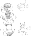
- FIG.s 12-15 an exploded view of an embodiment of the axial piston orientation of the hydromechanical, semi continuously variable transmission (sCVT) 1300, comprising: transmission housing base disc 110, comprising an inlet port 117 (not shown, see e.g., FIG.
- cylindrical piston housing 1302 having a proximal axial end and a distal axial end, and an internal radial surface and external radial surface, cylindrical piston housing 1302 defining a cylindrical space, configured to receive a plurality of axially oriented pistons 300 p not being part of said invention, wherein the proximal axial end of the p th piston 303 or 304 (see e.g., FIG.s 8C, 8D , 15B ) is operably coupled to transmission housing base disc 110.
- spool valve housing 105 j (not shown, see e.g., FIG 15B ), each having a proximal axial end and a distal axial end disposed radially, the spool valve housing having inlet port 117 and radial outlet port 113 being in fluid communication with a hydraulic pump and operably coupled to actuator 601 n with plurality of axially oriented pistons 300 p , each slidably coupled within the cylindrical space defined between the walls of cylindrical piston housing 1302 having internal wall 1303 (not shown, see e.g., FIG.
- each piston e.g., 304 having a proximal end and a distal end, wherein the proximal end extends into cylindrical piston housing 1302 having internal wall 1303, configured to engage drive shaft head 501.
- plurality of spool valves 200 q each disposed within the spool valve housing 105 j valve 200 q operably coupled to actuator 601 n and configured to regulate fluid communication between the distal end of piston 303 and the hydraulic fluid by exposing or blocking inlet radial port 114 and radial outlet port 113 of the hydraulic fluid.
- Encoder 400 is centrally coupled to transmission housing base disc 110 and coupled to the drive shaft 500.
- Transmission housing cover disc 1301, is coupled to the distal end of cylindrical transmission housing 1311. As shown in FIG.
- the conversion means operably coupling each q th spool valve 200 q to each n th servo motor (or actuator) 601 n
- Means 620 comprising cylindrical cap 623 having pin 625 disposed axially at the closed distal end, and configured to engage spool valve 200 (not shown, see e.g., FIG 12 ) and an open proximal end configured to receive dowel 605 operably coupled to servo motor 601 drive shaft and having sinusoidal groove 606 etched therein, wherein groove 606 is configured to detent member 622 can be coupled to cap 623 with bearing disc 621, and transmission housing's external wall 1302 (see e.g., FIG.
- FIG. 13B illustrates a magnified portion of detail B in FIG 12 not being part of said invention, showing an embodiment of axial piston 303, having a distal end with bracket 310 and frusto-conical roller bearing 311, whereby the angle defined by frusto-conical roller bearing 311 is configured to assure the wider base of frusto conical roller bearing 311 and the narrower end of the frusto-conical roller bearing 311 rotate at the same speed thus preventing unnecessary friction and heat.
- Bracket 310 extends longer at the internal wall of cylindrical drive shaft head 501.
- FIG. 14 not being part of said invention, illustrating in FIG 14A front isometric view of axial configuration of the axial piston orientation of the hydromechanical, semi continuously variable transmission (sCVT) 1300 (see e.g., FIG 12 ), without cylindrical piston housing 1302, and with drive shaft 500, extending through transmission housing cover disc 1301 at the distal end, while proximal end is operably coupled to encoder 400.
- cylindrical drive shaft head 501 defines a sinusoidal surface (or lip, 502 not shown, see e.g., FIG.
- actuators 601 n can be a servo motor, having lead 650, motor portion 640, motor gear assembly 645 and servo motor encoder 648.
- FIG 14B showing a rear isometric view with only a couple of pistons and without cylindrical piston housing 1302, for illustration purposes only.
- drive shaft 500 extending through transmission housing cover disc 1301 at the distal end, while proximal end is operably coupled to bearing 112.
- cylindrical drive shaft head 501 defines a sinusoidal surface (or lip) configured to be rotated by pistons 300 p , for example, friction piston 304, or roller piston 303 operably coupled to cylindrical transmission housing 1311, comprising outlet port 119.
- roller piston 303 having a distal end comprising bracket 310 with and frusto-conical roller bearing 311, whereby the angle defined by frusto-conical roller bearing 311 is configured to assure the wider base of frusto conical roller bearing 311 and the narrower end of the frusto-conical roller bearing 311 rotate at the same speed thus preventing unnecessary friction and heat.
- Bracket 310 extends longer at the internal wall of cylindrical drive shaft head 501.
- FIG. 15 not being part of said invention, illustrating a rear view of the axial piston orientation of the hydromechanical, semi continuously variable transmission (sCVT) 1300 (see e.g., FIG. 12 ), with actuators (or servo motors) 601n, oriented axially around transmission housing base disc 110, defining hydraulic fluid inlet port 117, with actuator lead 650 and encoder 648 visible, as well as hydraulic fluid outlet port 119.
- FIG 15A also defines cross section B-B, illustrated in detail in FIG. 15B .
- FIG. 15B illustrating cross section F-F in FIG 15A of the axial piston orientation of the hydromechanical, semi continuously variable transmission (sCVT) 1300, comprising: transmission housing base disc 110 transmission housing is 1302, 110 is rear part with inlet 117 and radial fluid inlet port114 (see e.g.
- FIG.-12 and holes connection between inlet 117 and radial inlet port 114, comprising inlet port 117 coupled to torus inlet manifold 114 for a hydraulic fluid with cylindrical piston housing 1302 having a proximal axial end and a distal axial end, and internal radial surface and external radial surface, cylindrical piston housing 1302 defining a cylindrical space, with internal wall 1303, configured to receive plurality of axially oriented pistons 300 p , (see e.g., FIG. 12 ) wherein the proximal axial end of the p th roller piston 303 or friction piston 304 is operably coupled to transmission housing base disc 110 of transmission housing comprised of a cylinder having external wall 1302 and internal wall 1303.
- Plurality of spool valve housing 105 j each having a proximal axial end and a distal axial end disposed radially, with outlet port 113 operably coupled to actuator 601 n having lead 650 with the plurality of axially oriented pistons 300 p , each p th piston slidably coupled within the cylindrical space defined between the walls of cylindrical piston housing 1302 having internal wall 1303, and each piston (e.g., friction piston 304) having a proximal end and a distal end, wherein the proximal end extends into cylindrical piston housing 1302 having internal wall 1303, configured to engage drive shaft head 501.
- each piston e.g., friction piston 304 having a proximal end and a distal end, wherein the proximal end extends into cylindrical piston housing 1302 having internal wall 1303, configured to engage drive shaft head 501.
- spool valves 200 q each disposed within the spool valve housing 105 j valve 200 operably coupled to actuator 601 n and configured to regulate fluid communication between the distal end of, e.g., roller piston 303 and the hydraulic fluid by exposing or blocking inlet port 117 coupled to torus inlet manifold 114 and outlet port 113 of the hydraulic fluid.
- Encoder 400 is centrally coupled to transmission housing base disc 110 and coupled to the drive shaft 500.
- Transmission housing cover disc 1301, is coupled to the distal end of cylindrical transmission housing 1311.
- plurality of actuators, or servo motors 601 n each operably coupled to the cylindrical transmission housing 1311 with means for converting each n th servo motor's 601 n rotational motion to reciprocating linear motion 620, the conversion means operably coupling each q th spool valve 200 q to each n th servo motor (or actuator) 601 n .
- biasing means 320 configured to bias roller piston 303 away from cylindrical drive shaft head 501, when the piston is not engaged by actuator 601 n via encoder 400.
- roller piston 303 further comprises a distal end comprising bracket 310 with and frusto-conical roller bearing 311, and wherein ball bearing 315 is sandwiched between internal arm of bracket 310 and internal wall of cylindrical drive shaft head 501.
- FIG. 16 Details of FIG 15B not being part of said invention, is further magnified in FIG. 16 , where FIG 16A illustrates detail D in FIG 15B , showing actuator cylinder member 602 n , means for converting each n th servo motor's 601 n rotational motion to reciprocating linear motion 620, the conversion means operably coupling each q th spool valve 200 q to each n th servo motor (or actuator) 601 n .
- means 620 comprising cylindrical cap 623 having pin 625 disposed axially at the closed distal end, and configured to engage spool valve 200 q and an open proximal end configured to receive dowel 605 operably coupled to actuator (or servo motor) 601 n drive shaft and having sinusoidal groove 606 (not shown, see e.g., FIG. 13A ) etched therein, wherein groove 606 is configured to receive bearing disc 621 rotatably coupled to detent member 622 (not shown, see e.g., FIG. 13A ), wherein disc 621 traverses the wall of cylindrical cap 623 along axial plane 633.
- a second assembly of detent 621 and rotatably coupled disc 622 is disposed at 180°, likewise configured to slidably engage groove 606 etched in dowel 605.
- biasing means 320 configured to bias roller piston 303 away from cylindrical drive shaft head 501, when the piston is not engaged by actuator 601 n via encoder 400.
- inlet port 117 coupled to torus inlet manifold 114, outlet port 113, and valve housing 105 j .
- roller piston 303 further comprises a distal end comprising bracket 310 with and frusto-conical roller bearing 311 is operably coupled to bracket 310 arms with roller bearing shaft 312, and wherein ball bearing 315 is sandwiched between internal arm of bracket 310 and internal wall of cylindrical drive shaft head 501 and is configured to both roll and turn while piston 303 is rolling and in contact with sinusoidal surface (or lip) 502, of cylindrical drive shaft head 501.
- biasing means 320 configured to bias roller piston 303 away from cylindrical drive shaft head 501, when the piston is not engaged.
- FIG. 17 showing an isometric view ( FIG 17A ) and top view ( FIG 17B ) of an alternate embodiment of drive shaft 500, having a distal end and a proximal end, drive shaft 500 having a drive shaft head 501 defining a cylinder, the cylinder having an internal surface and external surface and being closed at the distal end, with the proximal end defining a sinusoidal surface (or lip) 502 configured to engage the distal end of roller piston 303 or friction piston 304 (not shown, see e.g. FIG 14B ).
- sinusoidal lip 502 is not continuous and at the minima and maxima points, the curvature changes, and can be radial in shape and not in parabolic shape.
- the radial minima and maxima of the wave surfaces can be designed for adjusting transition zones, and the length can be adapted to alter the functionality of the transition mode, and could be different from one category (in other words, earth movers, ATV, pumps, sedans and the like), to another, this can allow the designer greater flexibility to design the transitions modes, and synchronize spool valve 200 q with elliptical drive shaft head 501revolutions.
- FIG 18 illustrates in FIG 18A the coupling between an actuator, or for example a servo motor 601 n , having lead 650, motor portion 640, motor gear assembly 645 and servo motor encoder 648, and means 620 comprising as shown in FIG18B .
- an actuator or for example a servo motor 601 n , having lead 650, motor portion 640, motor gear assembly 645 and servo motor encoder 648, and means 620 comprising as shown in FIG18B .
- cylindrical cap 623 having pin 625 disposed axially at the closed distal end, and configured to engage spool valve 200 (not shown , see e.g., FIG 15B ) and an open proximal end configured to receive dowel 605 operably coupled to servo motor 601 drive shaft and having sinusoidal groove 606 etched therein, wherein groove 606 is configured to receive disc 621 rotatably coupled to detent member 622, wherein disc 621 traverses the wall of cylindrical cap 623.
- a second assembly of detent 621 and rotatably coupled disc 622 is disposed at 180°, likewise configured to slidably engage groove 606 etched in dowel 605.
- FIG. 20 illustrating an embodiment of a vehicle comprising the hydromechanical continuous variable transmission (sCVDM or sCMRP module) 100 described herein located at each wheel hub.
- sCVDM hydromechanical continuous variable transmission
- FIG. 21 is a schematic view of the components in an embodiment of a vehicle comprising the radial orientation hydromechanical continuous variable transmission 100 described herein which schematically illustrates the electronic and mechanical Hydromechanical sCVT system.
- the system can comprise an efficient pump (e.g., the axially oriented piston sCVDP 1300 described herein) operably coupled to the engine shaft, and bypass subassembly, sensors, control box CPU, accumulator system, friction control valve, and reservoir container to filtered and cool the hydraulic oil, and electronic Hydromechanical sCVT shaft optionally coupled to each wheel shaft.
- an efficient pump e.g., the axially oriented piston sCVDP 1300 described herein
- the term “coupled”, including its various forms such as “operably coupling”, “operably coupled”, “coupling” or “couplable”, refers to and comprises any direct or indirect, structural coupling, connection or attachment, or adaptation or capability for such a direct or indirect structural or operational coupling, connection or attachment, including integrally formed components and components which are coupled via or through another component or by the forming process.
- Indirect coupling may involve coupling through an intermediary member or adhesive, or abutting and otherwise resting against, whether frictionally or by separate means without any physical connection.
- the term “coupled”, including its various forms such as “operably coupling”, “operably coupled”, “coupling” or “couplable”, refers to and comprises circumstances whereby two or more components in communicate with each other.
- “Communicate” and its derivatives e.g., a first component “communicates with” or “is in communication with” a second component
- grammatical variations thereof are used to indicate a structural, functional, mechanical, electrical, optical, or fluidic relationship, or any combination thereof, between two or more components or elements.
- the fact that one component is said to communicate with a second component is not intended to exclude the possibility that additional components can be present between, and/or operatively associated or engaged with, the first and second components.
- slidingly coupled is used in its broadest sense to refer to elements which are coupled in a way that permits one element to slide or translate within, or with respect to another element.
- engage and various forms thereof, when used with reference to the elliptical drive shaft head, refers to one or a plurality of coupled components, at least one of which is configured for releasably engage elliptical drive shaft head.
- this term encompasses both single part engaging elements and multi-part-assemblies.
- boss generally refers to protuberance on a part designed to add strength, facilitate alignment or motion, provide fastening, provide, etc.
- Exemplary boss elements include shapes such as a tab, detent, flange, pole, post, etc.
- biasing means refers to any device that provides a biasing force.
- Representative biasing elements include but are not limited to springs (e.g., elastomeric or metal springs, torsion springs, coil springs, leaf springs, tension springs, compression springs, extension springs, spiral springs, volute springs, flat springs, and the like), detents (e.g., springloaded detent balls, cones, wedges, cylinders, and the like), pneumatic devices, hydraulic devices, magnets, and the like, and combinations thereof.
- biasing means refers to one or more members that applies an urging force between two elements.
- a hydromechanical, continuously, discretely, variable transmission comprising: a transmission housing base disc, comprising an inlet port for a hydraulic fluid; a cylindrical transmission housing having a proximal axial end and a distal axial end, and an internal radial surface and external radial surface, the transmission housing defining a plurality of bores disposed radially at the distal axial end, wherein the proximal axial end is operably coupled to the transmission housing base disc; a plurality of spool valve housing each having a proximal axial end and a distal axial end disposed axially above the plurality of bores defined in the transmission housing, the spool valve housing having an inlet port and an outlet port and being in fluid communication with a hydraulic pump and operably coupled to an actuator; a plurality of pistons, each slidably coupled within the bore defined in the periphery of the cylindrical transmission housing having a proximal end and a distal end,
- a vehicle comprising: an engine; a hydraulic pump coupled to the engine; and a hydromechanical sCVT assembly, the hydromechanical sCVT in fluid communication with the hydraulic pump, wherein the hydromechanical sCVT is operably coupled to two wheels on opposite sides of the vehicle, wherein (xvi) the vehicle further comprises optionally, an additional hydromechanical sCVT of claim 1, the hydromechanical sCVT in fluid communication with the hydraulic pump coupled to each additional wheel of the vehicle; a high pressure accumulator; a low-pressure accumulator; and a reservoir container, all in fluid communication with the hydraulic pump, (xvii) and a hydraulic line having a proximal end coupled to the hydraulic pump and a distal end operably coupled to a proportional valve, wherein the proportional valve is operably coupled between at least a pair of the hydromechanical sCVT described herein,.
- a method of modulating the ratio between a motor's drive shaft and wheel or gear operably coupled to the motor comprising the steps of: coupling the motor drive shaft to a hydraulic pump; coupling the hydraulic pump to a hydromechanical, semi-continuous variable transmission (sCVT); coupling the hydromechanical, semi-continuous variable transmission to a gear or a wheel, whereby the hydromechanical, semi-continuous variable transmission is configured to rotate a drive shaft coupled to the gear or wheel using hydraulic fluid pumped by the hydraulic pump to actuate a plurality of pistons disposed radially around the drive shaft head; and, by adding or reducing the number of working pistons per revolution of the hydromechanical, semi-continuous variable transmission's drive shaft head, continuously varying the flow of the hydraulic fluid by discrete variable displacement per revolution, thereby changing the volume of displacement per revolution and modulating the ratio between a motor's drive shaft revolutions per minute and the revolutions per minute of a wheel or gear operably coupled to the motor, whereby (xviii)
- a hydromechanical, semi continuously variable transmission comprising: transmission housing base disc, defining an inlet port for a hydraulic fluid; a cylindrical piston housing having a proximal axial end and a distal axial end, and an internal radial surface and external radial surface, wherein the cylindrical piston housing defining a cylindrical space, configured to receive a plurality of axially oriented pistons, wherein the proximal axial end of the piston is operably coupled to transmission the housing base disc; a plurality of spool valve housing, each having a proximal axial end and a distal axial end disposed radially, the spool valve housing having inlet port and outlet port and being in fluid communication with a hydraulic pump and operably coupled to actuator; a plurality of axially oriented pistons, each slidably coupled within the cylindrical space defined between the walls of cylindrical piston housing having an internal wall, and each piston having a proximal axial end and a distal axial end, and an internal radial surface, wherein
Landscapes
- Engineering & Computer Science (AREA)
- General Engineering & Computer Science (AREA)
- Mechanical Engineering (AREA)
- Chemical & Material Sciences (AREA)
- Combustion & Propulsion (AREA)
- Physics & Mathematics (AREA)
- Fluid Mechanics (AREA)
- Transportation (AREA)
- Control Of Fluid Gearings (AREA)
- Control Of Transmission Device (AREA)
Claims (13)
- Hydromechanisches, stufenlos und diskret einstellbares Getriebe, umfassend:a. eine Getriebegehäuse-Basisplatte (110), umfassend einen Einlasskanal (117) für ein Hydraulikfluid;b. ein zylindrisches Getriebegehäuse (101), das ein proximales Axialende und ein distales Axialende sowie eine innere Radialfläche und eine äußere Radialfläche aufweist, wobei das Getriebegehäuse (101) mehrere Bohrungen (102) definiert, die radial am distalen Axialende angeordnet sind, wobei das proximale Axialende mit der Getriebegehäuse-Basisplatte (110) wirkgekoppelt ist;c. mehrere Schieberventilgehäuse (105), die jeweils ein proximales Axialende und ein distales Axialende aufweisen und axial über den mehreren in dem Getriebegehäuse (101) definierten Bohrungen (102) angeordnet sind, wobei die Schieberventilgehäuse (105) einen Einlasskanal (114) und einen Auslasskanal (113) aufweisen und mit einer Hydraulikpumpe in Fluidkommunikation und mit einem Aktor (602) wirkgekoppelt sind;d. mehrere Kolben (300), die jeweils verschiebbar in den Bohrungen (102), die im Randbereich des zylindrischen Getriebegehäuses (101) definiert sind, gekoppelt sind und ein proximales Ende und ein distales Ende aufweisen, wobei sich das proximale Ende in die innere Radialfläche des zylindrischen Getriebegehäuses (101) erstreckt und das distale Ende konfiguriert ist, um eine Antriebswelle (500) in Eingriff zu bringen;e. mehrere Schieberventile (200), die jeweils im entsprechenden Schieberventilgehäuse (105) angeordnet sind, wobei die Schieberventile (200) mit einem Aktor (602) wirkgekoppelt sind und konfiguriert sind, um Fluidkommunikation zwischen dem distalen Ende des Kolbens (300) und dem Hydraulikfluid durch Exponieren oder Blockieren des Einlasskanals (114) und des Auslasskanals (113) des Hydraulikfluids zu regeln;f. eine Antriebswelle (500), die ein distales Ende und ein proximales Ende aufweist, wobei die Antriebswelle einen Kopf mit einer Längsachse und einer Querachse senkrecht zur Längsachse aufweist, der am proximalen Ende der Antriebswelle angeordnet ist, wobei sich das distale Ende über eine Getriebegehäuse-Abdeckplatte (111) hinaus erstreckt und mit einem Rad oder Zahnrad wirkgekoppelt ist und das proximale Ende mit einem Kodierer (400) wirkgekoppelt ist;
undg. mehrere Aktoren (602), die jeweils mit dem Ventil (200) wirkgekoppelt sind;dadurch gekennzeichnet, dass:h. der Antriebswellenkopf ein elliptischer Kopf (501) oder ein quadratischer Kopf (510) ist, wobei er jeweils zwei diametral gegenüberliegende Arbeitsbereiche, zwei diametral gegenüberliegende Entladebereiche und zwei diametral gegenüberliegende Übergangsbereiche definiert;i. der Kodierer (400) mit der Getriebegehäuse-Basisplatte (110) zentral gekoppelt ist und mit dem elliptischen Antriebswellenkopf (501) oder dem quadratischen Antriebswellenkopf gekoppelt ist;j. die Getriebegehäuse-Abdeckplatte (111) mit dem distalen Ende des zylindrischen Getriebegehäuses (101) gekoppelt ist;und dass es ferner Folgendes umfasst:k. ein Steuermodul (100), das konfiguriert ist, um Eingaben von mehreren Sensoren zu empfangen und eine vorbestimmte Anzahl von Kolben (300) an einer vorbestimmten Position entlang des Randbereichs des zylindrischen Getriebegehäuses (101) in Eingriff zu bringen, wobei die Position der Aktoren (602) konfiguriert ist, um dem elliptischen Antriebswellenkopf (501) oder dem quadratischen Antriebswellenkopf kontinuierliche Radialbewegung zu übertragen, wobei die Anzahl von in Eingriff gebrachten Kolben (300) von den von den mehreren Sensoren empfangenen Eingaben abhängt. - Hydromechanisches Getriebe nach Anspruch 1, wobei die mehreren Bohrungen zwischen 5 und 168 Bohrungen umfassen.
- Hydromechanisches Getriebe nach Anspruch 1, wobei der elliptische Antriebswellenkopf ferner eine mit dem elliptischen Antriebswellenkopf wirkgekoppelte Radialschicht umfasst, die konfiguriert ist, um sich unabhängig vom elliptischen Antriebswellenkopf um die Antriebswelle zu drehen.
- Hydromechanisches Getriebe nach Anspruch 3, das zylindrische Lager aufweist, die axial zwischen der Radialschicht und dem elliptischen Antriebswellenkopf angeordnet sind.
- Hydromechanisches Getriebe nach Anspruch 1, wobei das proximale Kolbenende mit einem Lager wirkgekoppelt ist, das konfiguriert ist, um den Randbereich des elliptischen Antriebswellenkopfs in Eingriff zu bringen.
- Hydromechanisches Getriebe nach Anspruch 1, wobei die Eingaben an das Steuermodul von einem Rad- oder Zahnrad-Drehmomentsensor, dem Antriebswellen-Drehmomentsensor, dem Kodierer, einem Motor-Umdrehungen-pro-Minute- (U/min-) Sensor oder einem Zahnrad- oder Rad-Umdrehungen-pro-Minute- (U/min-) Sensor, einem Hydraulikfluiddrucksensor oder einer Kombination, welche die vorangegangenen umfasst, empfangen werden.
- Hydromechanisches Getriebe nach Anspruch 6, wobei an den Scheitelpunkten der Ellipse, die durch den Ellipsenkopf definiert wird, die Haupt- und Nebenhalbachse unterschiedlich sind und einen kreisförmigen Bogen zwischen dem Zentralwinkel von etwa 2° und etwa 20° definieren, mit Radien, die kürzer bzw. länger als die Haupt- und Nebenhalbachse an der restlichen Ellipsenkrümmung sind.
- Hydromechanisches Getriebe nach Anspruch 6, wobei bei einem festen oder steigenden Hydraulikfluiddruck gilt, je höher das Rad- oder Zahnraddrehmoment, desto größer die Anzahl an Kolben, die durch das Steuermodul im Arbeitsbereich in Eingriff gebracht sind.
- Hydromechanisches Getriebe nach Anspruch 6, wobei bei einer festen oder abnehmenden auf das Rad oder Zahnrad aufgebrachten Last gilt, je höher der hydraulische Druck, desto kleiner die Anzahl an Kolben, die durch das Steuermodul in der Arbeitszone in Eingriff gebracht sind.
- Hydromechanisches Getriebe nach Anspruch 1, wobei das Schieberventil ein Drehventil ist.
- Hydromechanisches Getriebe nach Anspruch 10, wobei der Aktor ein Servomotor ist, der konfiguriert ist, um das Drehschieberventil zu drehen.
- Hydromechanisches Getriebe nach Anspruch 1, wobei der Aktor ein Servomotor ist, der ferner Mittel zum Umwandeln von Drehbewegung in lineare Hin- und Herbewegung umfasst, wobei die Mittel zum Umwandeln von Drehbewegung in lineare Hin- und Herbewegung mit dem Schieberventil wirkgekoppelt sind.
- Hydromechanisches Getriebe nach Anspruch 1, wobei die nicht in Eingriff gebrachten Kolben von dem elliptischen Antriebswellenkopf weg vorgespannt sind.
Applications Claiming Priority (2)
| Application Number | Priority Date | Filing Date | Title |
|---|---|---|---|
| US14/161,076 US9353768B2 (en) | 2013-01-31 | 2014-01-22 | Hydromechanical continuously variable transmission |
| PCT/IL2015/050058 WO2015111042A1 (en) | 2014-01-22 | 2015-01-19 | Hydromechanical continuously variable transmission |
Publications (3)
| Publication Number | Publication Date |
|---|---|
| EP3097325A1 EP3097325A1 (de) | 2016-11-30 |
| EP3097325A4 EP3097325A4 (de) | 2017-11-15 |
| EP3097325B1 true EP3097325B1 (de) | 2019-09-04 |
Family
ID=53680917
Family Applications (1)
| Application Number | Title | Priority Date | Filing Date |
|---|---|---|---|
| EP15740371.8A Active EP3097325B1 (de) | 2014-01-22 | 2015-01-19 | Stufenloses hydromechanisches getriebe |
Country Status (3)
| Country | Link |
|---|---|
| US (1) | US9353768B2 (de) |
| EP (1) | EP3097325B1 (de) |
| WO (1) | WO2015111042A1 (de) |
Families Citing this family (19)
| Publication number | Priority date | Publication date | Assignee | Title |
|---|---|---|---|---|
| JP5968501B1 (ja) * | 2015-06-01 | 2016-08-10 | 三菱電機株式会社 | 車載電子制御装置 |
| US12276420B2 (en) | 2016-02-03 | 2025-04-15 | Strong Force Iot Portfolio 2016, Llc | Industrial internet of things smart heating systems and methods that produce and use hydrogen fuel |
| US10983507B2 (en) | 2016-05-09 | 2021-04-20 | Strong Force Iot Portfolio 2016, Llc | Method for data collection and frequency analysis with self-organization functionality |
| US11009865B2 (en) | 2016-05-09 | 2021-05-18 | Strong Force Iot Portfolio 2016, Llc | Methods and systems for a noise pattern data marketplace in an industrial internet of things environment |
| US11327475B2 (en) | 2016-05-09 | 2022-05-10 | Strong Force Iot Portfolio 2016, Llc | Methods and systems for intelligent collection and analysis of vehicle data |
| US11774944B2 (en) | 2016-05-09 | 2023-10-03 | Strong Force Iot Portfolio 2016, Llc | Methods and systems for the industrial internet of things |
| JP7454160B2 (ja) | 2016-05-09 | 2024-03-22 | ストロング フォース アイオーティ ポートフォリオ 2016,エルエルシー | 産業用のモノのインターネットのための方法およびシステム |
| CN107401585A (zh) * | 2016-05-20 | 2017-11-28 | 舒健平 | 齿轮与滚锥复合无级变速器 |
| US11237546B2 (en) | 2016-06-15 | 2022-02-01 | Strong Force loT Portfolio 2016, LLC | Method and system of modifying a data collection trajectory for vehicles |
| NL2019045B1 (en) * | 2017-06-09 | 2018-12-17 | Delft Offshore Turbine B V | Wind turbine generator with hydraulic pump |
| US10908602B2 (en) | 2017-08-02 | 2021-02-02 | Strong Force Iot Portfolio 2016, Llc | Systems and methods for network-sensitive data collection |
| EP3662331A4 (de) | 2017-08-02 | 2021-04-28 | Strong Force Iot Portfolio 2016, LLC | Verfahren und systeme zur detektion in einer industriellen internet-der-dinge-datenerfassungsumgebung mit grossen datenmengen |
| US11143276B2 (en) * | 2018-02-27 | 2021-10-12 | Dieter Gerhard Fahrni | Continuously variable transmission and method for operating a continuously variable transmission |
| US20200133254A1 (en) | 2018-05-07 | 2020-04-30 | Strong Force Iot Portfolio 2016, Llc | Methods and systems for data collection, learning, and streaming of machine signals for part identification and operating characteristics determination using the industrial internet of things |
| WO2020123726A1 (en) * | 2018-12-11 | 2020-06-18 | Kline Robert D | Variable output, hydraulic drive system |
| JP7549843B2 (ja) | 2019-01-13 | 2024-09-12 | ストロング フォース アイオーティ ポートフォリオ 2016,エルエルシー | 産業環境の監視及び管理のための方法、システム、キット、及び装置 |
| CN112202292A (zh) * | 2020-08-24 | 2021-01-08 | 扬州市神威机械设备有限公司 | 一种紧凑型电液推杆用电机 |
| CN113309755B (zh) * | 2021-06-21 | 2022-03-25 | 浙江大学 | 一种低速大扭矩复合式液压马达 |
| CN115306670B (zh) * | 2022-01-21 | 2023-06-16 | 衢州学院 | 一种基于triz原理的压缩机优化结构 |
Family Cites Families (9)
| Publication number | Priority date | Publication date | Assignee | Title |
|---|---|---|---|---|
| US2648952A (en) * | 1948-02-14 | 1953-08-18 | Don E Dasher | Rotary pump and motor hydraulic transmission |
| US3229538A (en) * | 1961-09-25 | 1966-01-18 | Roller Gear Ltd | Variable speed drive transmission |
| DE1503356A1 (de) | 1963-10-14 | 1970-01-02 | Heinrich Steiner | Hydraulischer Radialkolben-Motor |
| US5076057A (en) * | 1989-04-21 | 1991-12-31 | Honda Giken Kogyo Kabushiki Kaisha | Hydromechanical continuously variable transmission employing plunger-type hydraulic unit |
| US5244356A (en) * | 1990-05-23 | 1993-09-14 | Daiichi Electric Kabushiki Kaisha | Hydraulic piston apparatus |
| FI118233B (fi) * | 2003-04-01 | 2007-08-31 | Sampo Hydraulics Oy | Radiaalimäntähydraulimoottori ja menetelmä radiaalimäntähydraulimoottorin säädössä |
| US7484944B2 (en) * | 2003-08-11 | 2009-02-03 | Kasmer Thomas E | Rotary vane pump seal |
| US7588119B2 (en) * | 2006-04-12 | 2009-09-15 | Gm Global Technology Operations, Inc. | Hydrostatic retarder pump and motor |
| DE102008028547B4 (de) * | 2008-06-16 | 2022-07-07 | Danfoss Power Solutions Gmbh & Co. Ohg | Mobile Arbeitsmaschine |
-
2014
- 2014-01-22 US US14/161,076 patent/US9353768B2/en active Active
-
2015
- 2015-01-19 WO PCT/IL2015/050058 patent/WO2015111042A1/en not_active Ceased
- 2015-01-19 EP EP15740371.8A patent/EP3097325B1/de active Active
Non-Patent Citations (1)
| Title |
|---|
| None * |
Also Published As
| Publication number | Publication date |
|---|---|
| US20150354607A1 (en) | 2015-12-10 |
| EP3097325A4 (de) | 2017-11-15 |
| US9353768B2 (en) | 2016-05-31 |
| WO2015111042A1 (en) | 2015-07-30 |
| EP3097325A1 (de) | 2016-11-30 |
Similar Documents
| Publication | Publication Date | Title |
|---|---|---|
| EP3097325B1 (de) | Stufenloses hydromechanisches getriebe | |
| US10138729B2 (en) | Drive assembly with pressure force aggregating piston arrangement for hydraulic motor speed/torque selector | |
| US7412828B1 (en) | Adjustable hydraulic motor apparatus | |
| US20080276609A1 (en) | Dual hydraulic machine transmission | |
| US20020139604A1 (en) | Auxiliary solenoid controlled variable displacement power steering pump | |
| CN102333956A (zh) | 直接控制线性变排量叶片泵 | |
| EP1580060B1 (de) | Hydrostatische Antriebseinheit | |
| NL2011584C2 (en) | Transmission. | |
| EA010848B1 (ru) | Гидростатическая аксиально-поршневая машина и применение такой машины | |
| CN101550999A (zh) | 液压无级变速驱动器 | |
| EP1054175B1 (de) | Kraftübertragungsmechanismus | |
| US20210301816A1 (en) | Variable displacement gerotor pump | |
| US6672850B2 (en) | Torque control oil pump with low parasitic loss and rapid pressure transient response | |
| US20030032517A1 (en) | Infinitely variable ratio transmission five piston variator | |
| KR102370387B1 (ko) | 가변 용량 지로터 펌프 | |
| AU2006259387B2 (en) | Dual hydraulic machine transmission | |
| RU2385434C1 (ru) | Бесступенчатая трансмиссия | |
| US20230250819A1 (en) | Variable displacement gerotor pump | |
| AU772010B2 (en) | Variable displacement pump | |
| EP0890036A1 (de) | Hydrostatische kupplung mit einer planetenartigen zahnradpumpe | |
| JP2009121637A (ja) | 流体装置 | |
| RU2222440C1 (ru) | Устройство для снижения жесткости трансмиссии транспортного средства | |
| GB2325282A (en) | A continuously variable mechanical transmission | |
| GB2436594A (en) | A variable output pump assembly | |
| CN120003445A (zh) | 一种建压装置和电子伺服制动系统 |
Legal Events
| Date | Code | Title | Description |
|---|---|---|---|
| PUAI | Public reference made under article 153(3) epc to a published international application that has entered the european phase |
Free format text: ORIGINAL CODE: 0009012 |
|
| 17P | Request for examination filed |
Effective date: 20160809 |
|
| AK | Designated contracting states |
Kind code of ref document: A1 Designated state(s): AL AT BE BG CH CY CZ DE DK EE ES FI FR GB GR HR HU IE IS IT LI LT LU LV MC MK MT NL NO PL PT RO RS SE SI SK SM TR |
|
| AX | Request for extension of the european patent |
Extension state: BA ME |
|
| DAX | Request for extension of the european patent (deleted) | ||
| A4 | Supplementary search report drawn up and despatched |
Effective date: 20171016 |
|
| RIC1 | Information provided on ipc code assigned before grant |
Ipc: F04B 1/26 20060101ALI20171010BHEP Ipc: F16H 39/24 20060101ALI20171010BHEP Ipc: F16H 39/12 20060101ALI20171010BHEP Ipc: F16H 39/20 20060101ALI20171010BHEP Ipc: B60K 6/12 20060101ALI20171010BHEP Ipc: B60K 17/28 20060101ALI20171010BHEP Ipc: F03C 1/053 20060101ALI20171010BHEP Ipc: F04B 1/053 20060101ALI20171010BHEP Ipc: F16H 61/425 20100101ALI20171010BHEP Ipc: F16H 61/435 20100101ALI20171010BHEP Ipc: F16H 37/00 20060101AFI20171010BHEP Ipc: F16H 39/00 20060101ALI20171010BHEP |
|
| STAA | Information on the status of an ep patent application or granted ep patent |
Free format text: STATUS: EXAMINATION IS IN PROGRESS |
|
| 17Q | First examination report despatched |
Effective date: 20180906 |
|
| GRAP | Despatch of communication of intention to grant a patent |
Free format text: ORIGINAL CODE: EPIDOSNIGR1 |
|
| STAA | Information on the status of an ep patent application or granted ep patent |
Free format text: STATUS: GRANT OF PATENT IS INTENDED |
|
| INTG | Intention to grant announced |
Effective date: 20190320 |
|
| GRAS | Grant fee paid |
Free format text: ORIGINAL CODE: EPIDOSNIGR3 |
|
| GRAA | (expected) grant |
Free format text: ORIGINAL CODE: 0009210 |
|
| STAA | Information on the status of an ep patent application or granted ep patent |
Free format text: STATUS: THE PATENT HAS BEEN GRANTED |
|
| AK | Designated contracting states |
Kind code of ref document: B1 Designated state(s): AL AT BE BG CH CY CZ DE DK EE ES FI FR GB GR HR HU IE IS IT LI LT LU LV MC MK MT NL NO PL PT RO RS SE SI SK SM TR |
|
| REG | Reference to a national code |
Ref country code: GB Ref legal event code: FG4D |
|
| REG | Reference to a national code |
Ref country code: CH Ref legal event code: EP |
|
| REG | Reference to a national code |
Ref country code: AT Ref legal event code: REF Ref document number: 1175792 Country of ref document: AT Kind code of ref document: T Effective date: 20190915 |
|
| REG | Reference to a national code |
Ref country code: DE Ref legal event code: R096 Ref document number: 602015037173 Country of ref document: DE |
|
| REG | Reference to a national code |
Ref country code: IE Ref legal event code: FG4D |
|
| REG | Reference to a national code |
Ref country code: CH Ref legal event code: NV Representative=s name: DENNEMEYER AG, CH |
|
| REG | Reference to a national code |
Ref country code: NL Ref legal event code: FP |
|
| REG | Reference to a national code |
Ref country code: LT Ref legal event code: MG4D |
|
| PG25 | Lapsed in a contracting state [announced via postgrant information from national office to epo] |
Ref country code: LT Free format text: LAPSE BECAUSE OF FAILURE TO SUBMIT A TRANSLATION OF THE DESCRIPTION OR TO PAY THE FEE WITHIN THE PRESCRIBED TIME-LIMIT Effective date: 20190904 Ref country code: FI Free format text: LAPSE BECAUSE OF FAILURE TO SUBMIT A TRANSLATION OF THE DESCRIPTION OR TO PAY THE FEE WITHIN THE PRESCRIBED TIME-LIMIT Effective date: 20190904 Ref country code: BG Free format text: LAPSE BECAUSE OF FAILURE TO SUBMIT A TRANSLATION OF THE DESCRIPTION OR TO PAY THE FEE WITHIN THE PRESCRIBED TIME-LIMIT Effective date: 20191204 Ref country code: NO Free format text: LAPSE BECAUSE OF FAILURE TO SUBMIT A TRANSLATION OF THE DESCRIPTION OR TO PAY THE FEE WITHIN THE PRESCRIBED TIME-LIMIT Effective date: 20191204 Ref country code: SE Free format text: LAPSE BECAUSE OF FAILURE TO SUBMIT A TRANSLATION OF THE DESCRIPTION OR TO PAY THE FEE WITHIN THE PRESCRIBED TIME-LIMIT Effective date: 20190904 Ref country code: HR Free format text: LAPSE BECAUSE OF FAILURE TO SUBMIT A TRANSLATION OF THE DESCRIPTION OR TO PAY THE FEE WITHIN THE PRESCRIBED TIME-LIMIT Effective date: 20190904 |
|
| PG25 | Lapsed in a contracting state [announced via postgrant information from national office to epo] |
Ref country code: GR Free format text: LAPSE BECAUSE OF FAILURE TO SUBMIT A TRANSLATION OF THE DESCRIPTION OR TO PAY THE FEE WITHIN THE PRESCRIBED TIME-LIMIT Effective date: 20191205 Ref country code: RS Free format text: LAPSE BECAUSE OF FAILURE TO SUBMIT A TRANSLATION OF THE DESCRIPTION OR TO PAY THE FEE WITHIN THE PRESCRIBED TIME-LIMIT Effective date: 20190904 Ref country code: AL Free format text: LAPSE BECAUSE OF FAILURE TO SUBMIT A TRANSLATION OF THE DESCRIPTION OR TO PAY THE FEE WITHIN THE PRESCRIBED TIME-LIMIT Effective date: 20190904 Ref country code: LV Free format text: LAPSE BECAUSE OF FAILURE TO SUBMIT A TRANSLATION OF THE DESCRIPTION OR TO PAY THE FEE WITHIN THE PRESCRIBED TIME-LIMIT Effective date: 20190904 Ref country code: ES Free format text: LAPSE BECAUSE OF FAILURE TO SUBMIT A TRANSLATION OF THE DESCRIPTION OR TO PAY THE FEE WITHIN THE PRESCRIBED TIME-LIMIT Effective date: 20190904 |
|
| REG | Reference to a national code |
Ref country code: AT Ref legal event code: MK05 Ref document number: 1175792 Country of ref document: AT Kind code of ref document: T Effective date: 20190904 |
|
| PG25 | Lapsed in a contracting state [announced via postgrant information from national office to epo] |
Ref country code: PL Free format text: LAPSE BECAUSE OF FAILURE TO SUBMIT A TRANSLATION OF THE DESCRIPTION OR TO PAY THE FEE WITHIN THE PRESCRIBED TIME-LIMIT Effective date: 20190904 Ref country code: EE Free format text: LAPSE BECAUSE OF FAILURE TO SUBMIT A TRANSLATION OF THE DESCRIPTION OR TO PAY THE FEE WITHIN THE PRESCRIBED TIME-LIMIT Effective date: 20190904 Ref country code: AT Free format text: LAPSE BECAUSE OF FAILURE TO SUBMIT A TRANSLATION OF THE DESCRIPTION OR TO PAY THE FEE WITHIN THE PRESCRIBED TIME-LIMIT Effective date: 20190904 Ref country code: IT Free format text: LAPSE BECAUSE OF FAILURE TO SUBMIT A TRANSLATION OF THE DESCRIPTION OR TO PAY THE FEE WITHIN THE PRESCRIBED TIME-LIMIT Effective date: 20190904 Ref country code: RO Free format text: LAPSE BECAUSE OF FAILURE TO SUBMIT A TRANSLATION OF THE DESCRIPTION OR TO PAY THE FEE WITHIN THE PRESCRIBED TIME-LIMIT Effective date: 20190904 Ref country code: PT Free format text: LAPSE BECAUSE OF FAILURE TO SUBMIT A TRANSLATION OF THE DESCRIPTION OR TO PAY THE FEE WITHIN THE PRESCRIBED TIME-LIMIT Effective date: 20200106 |
|
| PG25 | Lapsed in a contracting state [announced via postgrant information from national office to epo] |
Ref country code: SM Free format text: LAPSE BECAUSE OF FAILURE TO SUBMIT A TRANSLATION OF THE DESCRIPTION OR TO PAY THE FEE WITHIN THE PRESCRIBED TIME-LIMIT Effective date: 20190904 Ref country code: SK Free format text: LAPSE BECAUSE OF FAILURE TO SUBMIT A TRANSLATION OF THE DESCRIPTION OR TO PAY THE FEE WITHIN THE PRESCRIBED TIME-LIMIT Effective date: 20190904 Ref country code: CZ Free format text: LAPSE BECAUSE OF FAILURE TO SUBMIT A TRANSLATION OF THE DESCRIPTION OR TO PAY THE FEE WITHIN THE PRESCRIBED TIME-LIMIT Effective date: 20190904 Ref country code: IS Free format text: LAPSE BECAUSE OF FAILURE TO SUBMIT A TRANSLATION OF THE DESCRIPTION OR TO PAY THE FEE WITHIN THE PRESCRIBED TIME-LIMIT Effective date: 20200224 |
|
| REG | Reference to a national code |
Ref country code: DE Ref legal event code: R097 Ref document number: 602015037173 Country of ref document: DE |
|
| PLBE | No opposition filed within time limit |
Free format text: ORIGINAL CODE: 0009261 |
|
| STAA | Information on the status of an ep patent application or granted ep patent |
Free format text: STATUS: NO OPPOSITION FILED WITHIN TIME LIMIT |
|
| PG2D | Information on lapse in contracting state deleted |
Ref country code: IS |
|
| PG25 | Lapsed in a contracting state [announced via postgrant information from national office to epo] |
Ref country code: DK Free format text: LAPSE BECAUSE OF FAILURE TO SUBMIT A TRANSLATION OF THE DESCRIPTION OR TO PAY THE FEE WITHIN THE PRESCRIBED TIME-LIMIT Effective date: 20190904 Ref country code: IS Free format text: LAPSE BECAUSE OF FAILURE TO SUBMIT A TRANSLATION OF THE DESCRIPTION OR TO PAY THE FEE WITHIN THE PRESCRIBED TIME-LIMIT Effective date: 20200105 |
|
| 26N | No opposition filed |
Effective date: 20200605 |
|
| PG25 | Lapsed in a contracting state [announced via postgrant information from national office to epo] |
Ref country code: SI Free format text: LAPSE BECAUSE OF FAILURE TO SUBMIT A TRANSLATION OF THE DESCRIPTION OR TO PAY THE FEE WITHIN THE PRESCRIBED TIME-LIMIT Effective date: 20190904 Ref country code: MC Free format text: LAPSE BECAUSE OF FAILURE TO SUBMIT A TRANSLATION OF THE DESCRIPTION OR TO PAY THE FEE WITHIN THE PRESCRIBED TIME-LIMIT Effective date: 20190904 |
|
| REG | Reference to a national code |
Ref country code: BE Ref legal event code: MM Effective date: 20200131 |
|
| PG25 | Lapsed in a contracting state [announced via postgrant information from national office to epo] |
Ref country code: LU Free format text: LAPSE BECAUSE OF NON-PAYMENT OF DUE FEES Effective date: 20200119 |
|
| PG25 | Lapsed in a contracting state [announced via postgrant information from national office to epo] |
Ref country code: BE Free format text: LAPSE BECAUSE OF NON-PAYMENT OF DUE FEES Effective date: 20200131 |
|
| PG25 | Lapsed in a contracting state [announced via postgrant information from national office to epo] |
Ref country code: IE Free format text: LAPSE BECAUSE OF NON-PAYMENT OF DUE FEES Effective date: 20200119 |
|
| PG25 | Lapsed in a contracting state [announced via postgrant information from national office to epo] |
Ref country code: TR Free format text: LAPSE BECAUSE OF FAILURE TO SUBMIT A TRANSLATION OF THE DESCRIPTION OR TO PAY THE FEE WITHIN THE PRESCRIBED TIME-LIMIT Effective date: 20190904 Ref country code: MT Free format text: LAPSE BECAUSE OF FAILURE TO SUBMIT A TRANSLATION OF THE DESCRIPTION OR TO PAY THE FEE WITHIN THE PRESCRIBED TIME-LIMIT Effective date: 20190904 Ref country code: CY Free format text: LAPSE BECAUSE OF FAILURE TO SUBMIT A TRANSLATION OF THE DESCRIPTION OR TO PAY THE FEE WITHIN THE PRESCRIBED TIME-LIMIT Effective date: 20190904 |
|
| PG25 | Lapsed in a contracting state [announced via postgrant information from national office to epo] |
Ref country code: MK Free format text: LAPSE BECAUSE OF FAILURE TO SUBMIT A TRANSLATION OF THE DESCRIPTION OR TO PAY THE FEE WITHIN THE PRESCRIBED TIME-LIMIT Effective date: 20190904 |
|
| PGFP | Annual fee paid to national office [announced via postgrant information from national office to epo] |
Ref country code: FR Payment date: 20230125 Year of fee payment: 9 Ref country code: CH Payment date: 20230131 Year of fee payment: 9 |
|
| PGFP | Annual fee paid to national office [announced via postgrant information from national office to epo] |
Ref country code: DE Payment date: 20230127 Year of fee payment: 9 |
|
| PGFP | Annual fee paid to national office [announced via postgrant information from national office to epo] |
Ref country code: NL Payment date: 20230127 Year of fee payment: 9 |
|
| PGFP | Annual fee paid to national office [announced via postgrant information from national office to epo] |
Ref country code: GB Payment date: 20240117 Year of fee payment: 10 |
|
| REG | Reference to a national code |
Ref country code: DE Ref legal event code: R119 Ref document number: 602015037173 Country of ref document: DE |
|
| REG | Reference to a national code |
Ref country code: CH Ref legal event code: PL |
|
| REG | Reference to a national code |
Ref country code: NL Ref legal event code: MM Effective date: 20240201 |
|
| PG25 | Lapsed in a contracting state [announced via postgrant information from national office to epo] |
Ref country code: DE Free format text: LAPSE BECAUSE OF NON-PAYMENT OF DUE FEES Effective date: 20240801 |
|
| PG25 | Lapsed in a contracting state [announced via postgrant information from national office to epo] |
Ref country code: FR Free format text: LAPSE BECAUSE OF NON-PAYMENT OF DUE FEES Effective date: 20240131 |
|
| PG25 | Lapsed in a contracting state [announced via postgrant information from national office to epo] |
Ref country code: NL Free format text: LAPSE BECAUSE OF NON-PAYMENT OF DUE FEES Effective date: 20240201 |
|
| PG25 | Lapsed in a contracting state [announced via postgrant information from national office to epo] |
Ref country code: CH Free format text: LAPSE BECAUSE OF NON-PAYMENT OF DUE FEES Effective date: 20240131 |
|
| PG25 | Lapsed in a contracting state [announced via postgrant information from national office to epo] |
Ref country code: NL Free format text: LAPSE BECAUSE OF NON-PAYMENT OF DUE FEES Effective date: 20240201 Ref country code: FR Free format text: LAPSE BECAUSE OF NON-PAYMENT OF DUE FEES Effective date: 20240131 Ref country code: DE Free format text: LAPSE BECAUSE OF NON-PAYMENT OF DUE FEES Effective date: 20240801 Ref country code: CH Free format text: LAPSE BECAUSE OF NON-PAYMENT OF DUE FEES Effective date: 20240131 |
|
| GBPC | Gb: european patent ceased through non-payment of renewal fee |
Effective date: 20250119 |
|
| PG25 | Lapsed in a contracting state [announced via postgrant information from national office to epo] |
Ref country code: GB Free format text: LAPSE BECAUSE OF NON-PAYMENT OF DUE FEES Effective date: 20250119 |