EP3096933B1 - Verfahren und vorrichtung zur herstellung von rohrschalen und damit hergestellte rohrschale - Google Patents
Verfahren und vorrichtung zur herstellung von rohrschalen und damit hergestellte rohrschale Download PDFInfo
- Publication number
- EP3096933B1 EP3096933B1 EP15701003.4A EP15701003A EP3096933B1 EP 3096933 B1 EP3096933 B1 EP 3096933B1 EP 15701003 A EP15701003 A EP 15701003A EP 3096933 B1 EP3096933 B1 EP 3096933B1
- Authority
- EP
- European Patent Office
- Prior art keywords
- winding core
- section
- pipe shell
- pipe
- winding
- Prior art date
- Legal status (The legal status is an assumption and is not a legal conclusion. Google has not performed a legal analysis and makes no representation as to the accuracy of the status listed.)
- Active
Links
Images

Classifications
-
- B—PERFORMING OPERATIONS; TRANSPORTING
- B29—WORKING OF PLASTICS; WORKING OF SUBSTANCES IN A PLASTIC STATE IN GENERAL
- B29C—SHAPING OR JOINING OF PLASTICS; SHAPING OF MATERIAL IN A PLASTIC STATE, NOT OTHERWISE PROVIDED FOR; AFTER-TREATMENT OF THE SHAPED PRODUCTS, e.g. REPAIRING
- B29C53/00—Shaping by bending, folding, twisting, straightening or flattening; Apparatus therefor
- B29C53/56—Winding and joining, e.g. winding spirally
- B29C53/566—Winding and joining, e.g. winding spirally for making tubular articles followed by compression
-
- B—PERFORMING OPERATIONS; TRANSPORTING
- B29—WORKING OF PLASTICS; WORKING OF SUBSTANCES IN A PLASTIC STATE IN GENERAL
- B29C—SHAPING OR JOINING OF PLASTICS; SHAPING OF MATERIAL IN A PLASTIC STATE, NOT OTHERWISE PROVIDED FOR; AFTER-TREATMENT OF THE SHAPED PRODUCTS, e.g. REPAIRING
- B29C53/00—Shaping by bending, folding, twisting, straightening or flattening; Apparatus therefor
- B29C53/80—Component parts, details or accessories; Auxiliary operations
- B29C53/82—Cores or mandrels
- B29C53/821—Mandrels especially adapted for winding and joining
-
- B—PERFORMING OPERATIONS; TRANSPORTING
- B29—WORKING OF PLASTICS; WORKING OF SUBSTANCES IN A PLASTIC STATE IN GENERAL
- B29D—PRODUCING PARTICULAR ARTICLES FROM PLASTICS OR FROM SUBSTANCES IN A PLASTIC STATE
- B29D23/00—Producing tubular articles
- B29D23/001—Pipes; Pipe joints
Definitions
- the invention relates to a method for manufacturing pipe shells of bound mineral wool, wherein a web section of a mineral wool web provided with a thermosetting, but still unset binding agent which yields the desired wall thickness of the pipe shell is wound around a rotatingly driven pipe-shaped winding core, and wherein the pipe shell thus formed and still unset is set at the outer circumference of the winding core by the action of heat and the winding core is pulled out of the set pipe shell.
- the invention further relates to a device according to the preamble of claim 7 and a pipe shell according to claim 13.
- Pipe shells serve the heat and/or sound insulation of piping or other pipe-shaped elements. Due to the broad field of application involved, and in particular the great number of pieces involved, it is in general the profitableness of the manufacturing of such pipe shells that lies within the center of observations among experts.
- This known method relates in particular to an advantageous manner of setting the binding agent in the pipe shell.
- the winding core has circumferential perforations through which hot gas can be directed to the inner surface of the pipe shell and through the wall thickness of the pipe shell. This results in a very homogeneous setting of the pipe shells in very short time.
- the winding core has a polygonal cross-section, wherein the pipe shell also obtains a polygonal cross-section during the winding process, and in that the winding core is driven at inconstant angular speed, wherein the angular speed of the winding core varies as a function of the effective distance of the respective region of the web section which meets the outer circumferential face from the axis of rotation of the winding core, so that the tensile forces acting on the web section to be wound up during the winding process vary at a lesser degree and are in particular substantially constant.
- the method according to the invention thus makes it possible for the first time to manufacture pipe shells with a non-circular cross-section, namely a polygonal cross-section, by a winding process. This enables a distinctly more efficient way of manufacturing of such polygonal pipe shells.
- the pipe shells manufactured this way are also characterized by a particularly good homogeneity of the insulating material, so that particularly good heat and/or sound insulation properties can be achieved.
- the insulating material in a more target-oriented and economical manner since less "oversize" for possible inhomogeneity has to be provided.
- a further advantage of the method according to the invention is that the mineral wool material to be wound up, despite the intrinsically inconstant course of movement, is not subject to excess strain in the course of the winding process, which could result in the destruction of the texture of the mineral wool.
- the method according to the invention takes account of this finding and provides a control of the angular speed of the winding core such that, at any time of the winding process, substantially the same circumferential speed is given for pulling off the web section from a supply device, and hence substantially constant tensile forces act on the mineral wool material.
- the circumferential speed is directly dependent on the angular speed and/or the rotational speed and the effective radius.
- the method according to the invention thus renders it possible to provide polygonal pipe shells with high dimensional accuracy, accuracy of fit, and with particularly homogeneous material properties in mass production in very short time.
- DE 23 09 866 A indeed discloses a manufacturing method for a pipe shell in which a winding core of polygonal shape may also be used.
- this method serves to form a circular pipe shell which is elastically deformable in partial regions on the inner side.
- elastically compressible bars are provided on the inner side of the pipe shell for this purpose. If the triangular core suggested in one embodiment is used as a winding mandrel, these resilient bars obtain substantially the shape of plane connecting faces between rounded corner regions in the cross-section of the pipe shell.
- the amount of material in the region of the bars is substantially equal to the amount of material in the other regions of the pipe shell.
- the density in the wall of the pipe shell is accordingly smaller in the region of the bars than in the other regions, so that the bars are particularly well compressible.
- the angular speed of the winding core can be controlled such that the tensile forces acting on the web section during the winding process deviate from the target value by a maximum of 10 %.
- Practical tests have shown that the mineral wool material is adapted to reliably assume transverse tensile stresses within such a tolerance range without being damaged. Process reliability is thus increased.
- a further improvement of reliability of the performance of the method is achieved if the winding core is controlled such that the tensile forces deviate from the target value by a maximum of 5 %.
- the pipe shell obtains a square cross-section during the winding process, wherein a winding core with a substantially square cross-section is used.
- Such pipe shells can be used in a particularly good manner as an insulation for chimney systems and the like.
- the pipe shell obtains rounded corners in cross-section, wherein a winding core with rounded corner regions in cross-section is used for this purpose.
- a pipe shell in accordance with the invention which has been further developed in such a manner can thus enfold its heat insulation in a particularly efficient manner on the smallest possible space.
- cross-section of the pipe shell is designed with bar-shaped elevations at the inner face of plane shell regions, wherein a winding core with a cross-section of groove-shaped depressions at the outer side of plane face regions is used, bar-shaped elevations can also be provided on the pipe shells according to the invention. This achieves a stable contact of the pipe shell with the outer surface of the pipe body to be insulated, even if, due to manufacturing tolerances, a gap between these elements cannot be excluded.
- the web section to be wound up is pressed against the outer face of the winding core, and/or a reel possibly already available there, by means of a pressure element, such as in particular one end of a conveyor belt, wherein the pressure element, depending on the position of rotation of the winding core, is tracked with respect thereto such that a gap width between the pressure element and the outer face of the winding core, and/or of a reel possibly already available there, remains substantially constant.
- the tracking movement of the pressure element offsets the differing distances resulting from the contour of the winding core at the outer circumference thereof with respect to the axis of rotation and thus permanently cares for a suitable contact pressure of the fleece on the winding core.
- This enables a particularly uniform winding of the web section onto the winding core. Additionally, the damaging of the device components, the tearing of the fleece web in the case of too small a gap width, or the uncontrolled winding in the case of too large a gap are avoided.
- the outer circumference of the set pipe shell which is still supported on the winding core is finished in a material-removing manner in a processing station, in particular a grinding station, with a grinding element, wherein the winding core is driven at inconstant angular speed, and wherein the angular speed of the winding core varies as a function of the distance of the processing element acting on the outer circumference of the pipe shell from the axis of rotation of the winding core.
- a device for manufacturing pipe shells of bound mineral wool in accordance with the invention is designed with a winding station at which a web section of a mineral wool web provided with a thermosetting, but still unset binding agent which yields the desired wall thickness of the pipe shell is adapted to be wound around a rotatingly driven pipe-shaped winding core, a setting station for setting the pipe shell thus formed at the outer circumference of the winding core by the action of heat, and a pull-off station in which the winding core is adapted to be pulled out of the pipe shell.
- the device according to the invention is characterized in that the winding core has a polygonal cross-section and in that the device further comprises a control unit by means of which the winding core is driven at inconstant angular speed, wherein the angular speed of the winding core varies as a function of the effective distance of the respective region of the web section which meets the outer circumferential face from the axis of rotation of the winding core, so that the tensile forces acting on the web section to be wound up during the winding process vary at a lesser degree and are in particular substantially constant.
- the method according to the invention can thus be performed in a particularly advantageous manner with this device.
- the above-explained advantages with respect to the forming of improved pipe shells can be achieved therewith.
- a pipe shell with a polygonal cross-section which is manufactured by a method in accordance with the invention is provided pursuant to claim 13.
- This pipe shell comprises the advantages already explained above.
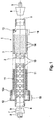
- reference number 1 designates the winding core as a whole.
- the winding core 1 consists of an inner support pipe 2 and an outer bearing pipe 3 for the pipe shell which is not illustrated in detail in Fig. 1 .
- the inner support pipe 2 comprises cone-shaped accommodations 4 and 5 at the two ends thereof.
- Rotation cones 6 and 7 as they are illustrated in a schematically simplified manner in Fig. 1 are adapted to cooperate with these accommodations 4 and 5.
- the rotation cone 6 merely serves the centered accommodation of the support pipe 2 so as to be able to drive it rotatingly by means of a driven shaft 8 of a rotary drive.
- This also applies to the rotation cone 7 which, however, comprises additionally a central channel 9 through which gas can be introduced into the interior of the support pipe 2 during the rotating movement.
- the friction entrainment at the accommodations 4 and/or 5 is, as a rule, sufficient. If required, a suitable form fit entrainment device may, however, also be provided.
- the support pipe 2 has relatively large perforation holes 10 through which hot air may get into an intermediate space 11 positioned between the outer circumference of the support pipe 2 and the inner circumference of the bearing pipe 3.
- the ends 12 and 13 of the bearing pipe 3 are connected in a substantially gas-tight manner with the outer circumference of the support pipe 2, so that the intermediate space 11 is closed laterally.
- the wall of the bearing pipe 3, however, comprises a plurality of small perforation openings 14 through which hot gas can flow from the intermediate space 11 through the wall of the bearing pipe 3 and then hits on the inner surface of the pipe shell which is not illustrated in detail in Fig. 1 , and flows through the wall thereof.
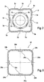
- the bearing tube 3 has a substantially square cross-section with plane face regions 3a which are each connected with one another by a rounded corner region 3b. In the middle of the plane face regions 3a, respective groove-shaped depressions 3c are additionally provided at the outer side.
- the perforation holes 14 have not been drawn here for simplification of the illustration.
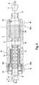
- the bearing pipe 2 comprises, at the end 12 or 13 at which the widening of the internal dimension of the pipe shell is to be performed, a projecting shoulder 12a whose dimension enlargement vis-à-vis the main part of the bearing pipe 2 corresponds to the end-side widening of the pipe shell 24.
- the chain dotted lines 24a each indicate up to which position the pulled-off blank of the pipe shell 24 is cut off during trimming.
- the shoulder 12a is positioned axially within the adjacent line 24a in the useful range of the finished pipe shell 24, so that the corresponding widening of the clear internal dimension takes effect at the finished product.
- the parts of the blank of the pipe shell 24 illustrated in Fig. 4 which are positioned axially outside of the lines 24a may be damaged during the pulling process since they are cut off during trimming. It is understood that, if such a shoulder 12a is used, the blank of the pipe shell 24 may only be pulled off via the end 13 of the bearing pipe 2 and/or the winding core 1 which is opposite to the shoulder 12a.
- a web section 17 of a mineral wool web is guided on a conveyor belt 18 to a winding station designated as a whole with 19.
- the web section 17 is produced by a mineral wool web being, in a per se known manner, torn off in a position desired for forming the web section, as is also explained in prior art pursuant to DE 197 04 988 A1 , so that reference may be made thereto.
- front and rear end regions of the web section 17 with gradually decreasing thickness are produced, so that a smooth transition of the beginning of the material and of the end of the material is achieved during the winding process on the winding core 1.
- the web section 17 is in this manner guided from the conveyor belt 18 to the winding station 19 in which a winding core 1, held between rotation cones 6 and 7 in the manner to be seen in Fig. 1 , is arranged above the output-side deflector roll 20 of the conveyor belt 18.
- the web section 17 thus runs into the gap between the deflector roll 20 and the winding core 1.
- the entrainment of the material of the web section 17 on the winding core 1 may be effected in that a rotation cone 7 with a gas channel 9 is used which is connected to a negative pressure source, as is the case and is explained in detail in prior art pursuant to DE 197 04 988 A1 , so that reference may be made thereto.
- the front end of the web section 17 is held at the outer circumference of the winding core 1 by negative pressure and thus wound.
- a flap roll 21 may be used which is, during the running of the web section 17 into the gap between the deflector roll 20 and the winding core 1, swiveled upward on swivel arms 22 around the axis of the deflector roll 20 and flaps the material of the front end of the web section 17 around the winding core 1.
- the rotational speed of the winding core 1 is variable such that the tensile forces acting on the web section 17 during the winding process are kept as constant as possible.
- a control unit that is not illustrated in the Figure is provided at the rotary drive which suitably controls the angular speed of the winding core 1 in an inconstant manner.
- the angular speed is lower than in the interposed plane face regions 3a.
- the tensile force acting during the winding process on the web section 17 to be wound up may be kept substantially constant. This prevents the mineral wool web from being torn.
- the rotational speed of the winding core 1 is further controlled such that a speed increased vis-à-vis the operating speed of the conveyor belt 18 and/or the circumferential speed of the deflector roll 20 results at the circumference thereof.
- the material of the web section 17 caught by the winding core 1 is subject to a tension and a stretching which further support the laminar orientation of the fibers, so that the fibers are arranged even better in the circumferential direction of the pipe shell and hence yield a favorable ⁇ value of the pipe shell.
- a certain homogenization of the material takes place in the web section 17 during the winding process.
- such a tensile strength ensures a tight contact of the material of the web section 17 at the circumference of the winding core 1 without the formation of wrinkles.
- the output-side end of the conveyor belt 18 is supported to be adjusted in height at 23.
- the deflector roll 20, depending on the position of rotation of the winding core 1 is tracked with respect to the latter so as to remain in contact and to provide a substantially constant gap width.
- the deflector roll 20 is tracked with respect to the pipe shell on the winding core 1 with increasing thickness of the reel, i.e. its height position is adapted to the current winding thickness.
- the flap roll 21 may, after the flapping of the front end of the web section 17, remain at the circumference of the winding core 1 and act as an additional pressure roll for the winding process.
- the winding core 1 with the material for the pipe shell designated with 24 positioned thereon is transferred to a setting station 25.
- the winding core 1 which is supported at its two ends of the support pipe 2 projecting from the material of the pipe shell 24 at accommodations 26 of a transport belt 27, is caught from both sides by rotation cones 7 with air channels 9, wherein the outer sheathing of the rotation cone 7 forms a substantially gas-tight connection with the conical accommodations 4 and 5 of the support pipe 2.
- hot air is conveyed into the interior of the support pipe 2 in this position, from where it may get into the intermediate space 11 via the perforations 10 of the support pipe 2 and from there via the wall of the bearing pipe 3 into the material of the pipe shell 24.
- the material of the pipe shell 24 is heated such that first of all the high water share contained in the binding agent evaporates and then the polymerization temperature is achieved. This results in a largely homogeneous setting of the material of the pipe shell 24 within short time.
- the inner surface of the pipe shell 24 is of excellent dimensional accuracy and smoothness.
- the outer surface still requires processing in the instant embodiment.
- the outer surface of the pipe shell 24 is ground with a grinding roll 29 in a grinding station 28, as is known per se. It is of great advantage that the inner side of the pipe shell 24 is still supported by the winding core 1, so that a wall thickness with high homogeneity and dimensional accuracy results by the adjustment of a desired distance between the outer face of the bearing pipe 3 and the circumferential face of the grinding roll 29. Since the pipe shell 24 was produced by winding around the winding core 1, perfect centricity also results from the grinding process. Thus, the pipe shell has extremely high homogeneity of setting and excellent surface quality both of the inner and of the outer surface with the best dimensional accuracy.
- the winding core 1 is driven at inconstant angular speed, wherein it varies as a function of the distance of the processing element acting on the outer circumference of the pipe shell 24 from the axis of rotation of the winding core 1.
- a finishing at the outer circumference of the set pipe shell 24 can be performed in a particularly efficient manner despite its polygonal shape.
- the processing takes place uniformly in any region, irrespective of whether the processing element in the processing station acts on a corner region or a plane face at the pipe shell 24.
- the setting station 25 and the grinding station 29 are encapsulated by a cover hood 30 from which air is sucked pursuant to the arrow 31. In this manner the vapor originating during the setting process and the abrasive dust originating during the grinding process are discharged.
- the winding core 1 is pulled out of the interior of the pipe shell 24.
- any suitable pulling device may be used, as it is, for instance, also illustrated and explained in DE 197 04 988 A1 , so that reference may be made thereto.
- the support pipe 2 may be provided with form fit engagement means at its end to be caught by the pulling device, said means enabling a form fit engagement of the pulling device, for instance a circumferential groove or projecting circumferential projections.
- the adjacent material above the end 12 and/or 13 of the bearing pipe 3 which forms the ring shoulder has not been set, as explained, and may thus be deformed easily during the pulling of the winding core.
- the pipe shell 24 is supplied to a trimming station 33 in which the lateral ends of the pipe shell are cut off at the chain dotted lines 24a with symbolically illustrated saws 34 (see Fig. 4 ), and the pipe shell 24 is thus cut to length, wherein well set and hence dimensionally stable front sides of the pipe shell 24 result.
- the finished pipe shell is here designated with 24'. From the trimming station 22 the pipe shell 24' finally gets to a receiving container 35 for transportation.
- the device operates in cycles to avoid that the hot air connections in the setting station 25 and the rotary mounting for the winding core 1 in the grinding station 28 have to be kept moving. Due to the very intensive uniform heating of the mineral wool material of the pipe shell 24 in the setting station 25 there results a cycle time of one pipe shell per minute, for example, wherein two or more hot air connections positioned side by side may also be provided in the setting station 25 if required so as to simultaneously set a plurality of pipe shells 24 in stations arranged one behind the other. With respect to the different internal dimensions of pipe shells 24 it is frequently sufficient to use winding cores 1 with equal support pipes 2, wherein different internal widths and/or end-side widened internal widths of the pipe shells 24 can be achieved by an appropriate widening of the intermediate space 11. Thus, all or at any rate many sizes of pipe shells 24' may be manufactured with one and the same support pipe dimension with respect to which the rotation cones 6 and 7 are optimized.
- Fig. 5 finally shows a section through a finished pipe shell 24'. It has a substantially square cross-section with plane shell regions 24a which are each connected with each other via rounded corner regions 24b. Respective bar-shaped elevations 24c are formed in the middle at the inner face of the plane shell regions 24a.
- the parameters of the controlled adjustment of the angular speed of the winding core are advantageously determined for the respective individual case by suitable tests. In this respect it is not necessary to adjust the deviation of the angular speed of the winding core such that the tensile forces acting during the winding process deviate from the target value by a maximum of 10 %. For some applications such as, for instance, with specific mineral wool materials or binding agent types, larger deviations are also possible without a relevant aggravation of the properties of the pipe shell occurring.
- the target value deviations indicated thus serve orientation purposes and give information about the regions in which good pipe shells can be achieved in a particularly reliable manner.
- the polygonal shape of the winding core and/or the pipe shell manufactured thereon is not restricted to a square shape. In some chimney systems or other fields of use, rectangular piping is also used. In various other applications, in particular in the case of elements with larger dimensions which are to be insulated, it is, however, also possible to use pipe shells with a hexagonal, octagonal or another polygonal cross-section. These cross-section shapes can also be produced without problems by providing an appropriately designed winding core by the method and/or the device in accordance with the invention.
- the radius of the rounded corners at the winding core and/or the pipe shell depends on the application and/or the design of the piping to be insulated. It may accordingly vary in wide ranges. It is in particular also possible that the corners in the cross-section of the winding core and/or the pipe shell are quasi not rounded, so that substantially exactly polygonal pipe shells are produced. This is in particular the case with pipe shells having more than four corners.
- the groove-shaped depressions at the outer side of the plane face regions at the winding core may then also be renounced.
- the pressure element which is pressed against the outer face of the winding core and which is adapted to be tracked may also be renounced. In simple cases a free pulling of the mineral wool web section from a feeding element or the like on the winding core is sufficient.
- the winding core is pulled out of the set pipe shell in axial direction.
- it is provided to slit the pipe shell longitudinally, so that the removal of the winding core through this slot is basically also possible.
Landscapes
- Engineering & Computer Science (AREA)
- Mechanical Engineering (AREA)
- Thermal Insulation (AREA)
Claims (15)
- Verfahren zum Herstellen von Rohrschalen (24') aus gebundener Mineralwolle, wobei ein Bahnabschnitt (17) einer Mineralwollebahn, die mit einem wärmehärtenden, doch immer noch unausgehärteten Bindemittel, das die geforderte Wanddicke der Rohrschale (24') ergibt, versehen ist, um einen drehend angetriebenen, rohrförmigen Wickelkern (1) gewickelt wird, und wobei die dadurch ausgebildete, doch immer noch unausgehärtete Rohrschale (24) durch Wärme an dem äußeren Umfang des Wickelkerns (1) ausgehärtet wird und der Wickelkern (1) aus der ausgehärteten Rohrschale (24') herausgezogen wird,
dadurch gekennzeichnet, dass
der Wickelkern (1) einen polygonalen Querschnitt aufweist, wobei die Rohrschale (24) während des Wickelvorgangs ebenfalls einen polygonalen Querschnitt erlangt, und
der Wickelkern (1) mit einer nicht konstanten Winkelgeschwindigkeit angetrieben wird, wobei die Winkelgeschwindigkeit des Wickelkerns (1) als eine Funktion des wirksamen Abstands des jeweiligen Bereichs des Bahnabschnitts (17), der von der Drehachse des Wickelkerns (1) auf die äußere Umfangsfläche trifft, so dass die Zugkräfte, die auf den Bahnabschnitt (17), der während des Wickelvorgangs aufzuwickeln ist, wirken, in einem geringeren Ausmaß variieren und besonders im Wesentlichen konstant sind. - Verfahren nach Anspruch 1, dadurch gekennzeichnet, dass die Winkelgeschwindigkeit des Wickelkerns (1) derart gesteuert wird, dass die auf den Bahnabschnitt (17) beim Wickelvorgang einwirkenden Zugkräfte um maximal 10 %, und insbesondere um maximal 5 %, vom Sollwert abweichen.
- Verfahren nach Anspruch 1 oder 2, dadurch gekennzeichnet, dass die Rohrschale (24) beim Wickeln einen quadratischen Querschnitt erhält, wobei ein Wickelkern (1) mit einem im Wesentlichen quadratischen Querschnitt eingesetzt wird, und wobei die Rohrschale (24) beim Wickeln vorzugsweise abgerundete Eckbereiche (24b) im Querschnitt erhält, wobei hierzu ein Wickelkern (1) mit im Querschnitt abgerundeten Eckbereichen (3b) eingesetzt wird.
- Verfahren nach einem der Ansprüche 1 bis 3, dadurch gekennzeichnet, dass die Rohrschale (24) im Querschnitt mit leistenförmigen Erhebungen (24c) an der Innenfläche von ebenen Schalenbereichen (24a) ausgebildet wird, wobei ein Wickelkern (1) mit im Querschnitt nutenförmigen Vertiefungen (3c) an der Außenseite von ebenen Flächenbereichen (3a) eingesetzt wird.
- Verfahren nach einem der Ansprüche 1 bis 4, dadurch gekennzeichnet, dass der aufzuwickelnde Bahnabschnitt (17) mittels einem Andruckelement, insbesondere einem Ende eines Förderbands (18), gegen die Außenfläche des Wickelkerns (1) bzw. einen dort ggf. bereits vorliegenden Wickel gedrückt wird, wobei das Andruckelement hierzu je nach Drehlage des Wickelkerns (1) gegenüber diesem derart nachgeführt wird, dass eine Spaltbreite zwischen dem Andruckelement und der Außenfläche des Wickelkerns (1) bzw. eines dort ggf. bereits vorliegenden Wickels im Wesentlichen konstant bleibt.
- Verfahren nach einem der Ansprüche 1 bis 5, dadurch gekennzeichnet, dass im Anschluss an die Aushärtung der Außenumfang der ausgehärteten, noch am Wickelkern (1) abgestützten Rohrschale (24) in einer Bearbeitungsstation, insbesondere einer Schleifstation (28) mit einem Schleifelement (29), materialgebend fertig bearbeitet wird, wobei der Wickelkern (1) mit einer nicht konstanten Winkelgeschwindigkeit angetrieben wird, und wobei die Winkelgeschwindigkeit des Wickelkerns (1) in Abhängigkeit vom Abstand des auf den Außenumfang der Rohrschale (24) einwirkenden Bearbeitungselements von der Drehachse des Wickelkerns (1) variiert.
- Vorrichtung zur Herstellung von Rohrschalen (24') aus gebundener Mineralwolle, mit
einer Wickelstation (19), an der ein die gewünschte Wanddicke der Rohrschale (24') ergebender Bahnabschnitt (17) einer mit thermisch aushärtbarem, jedoch noch unausgehärtetem Bindemittel versehenen Mineralwollebahn um einen drehend angetriebenen rohrförmigen Wickelkern (1) aufwickelbar ist,
einer Aushärtestation (25), zum Aushärten der so gebildeten Rohrschale (24) am Außenumfang des Wickelkernes (1) durch Wärmeeinwirkung, und
einer Abziehstation (32), in welcher der Wickelkern (1) aus der Rohrschale (24) herausziehbar ist,
dadurch gekennzeichnet,
dass der Wickelkern (1) einen polygonalen Querschnitt aufweist, und
dass die Vorrichtung ferner eine Steuerungseinheit aufweist, mittels welcher der Wickelkern (1) mit einer nicht konstanten Winkelgeschwindigkeit angetrieben wird, wobei die Winkelgeschwindigkeit des Wickelkerns (1) in Abhängigkeit vom wirksamen Abstand des jeweils auf die äußere Umfangsfläche auftreffenden Bereichs des Bahnabschnitts (17) von der Drehachse des Wickelkerns (1) variiert, so dass die auf den aufzuwickelnden Bahnabschnitt (17) beim Wickelvorgang einwirkenden Zugkräfte in geringerem Maße schwanken, insbesondere im Wesentlichen konstant sind. - Vorrichtung nach Anspruch 7, dadurch gekennzeichnet, dass die Steuerungs-einheit die Winkelgeschwindigkeit des Wickelkerns (1) derart steuert, dass die auf den Bahnabschnitt (17) beim Wickelvorgang einwirkenden Zugkräfte um maximal 10 %, und insbesondere um maximal 5 %, vom Sollwert abweichen.
- Vorrichtung nach Anspruch 7 oder 8, dadurch gekennzeichnet, dass der Wickelkern (1) einen im Wesentlichen quadratischen Querschnitt aufweist, wobei der Wickelkern (1) vorzugsweise im Querschnitt abgerundete Eckbereiche (3b) aufweist.
- Vorrichtung nach einem der Ansprüche 7 bis 9, dadurch gekennzeichnet, dass der Wickelkern (1) im Querschnitt in ebenen Flächenbereichen (3a) außenseitig nutenförmige Vertiefungen (3c) aufweist.
- Vorrichtung nach einem der Ansprüche 7 bis 10, dadurch gekennzeichnet, dass ferner ein Andruckelement, insbesondere einem Ende eines Förderbands (18), angeordnet ist, mittels dem der aufzuwickelnde Bahnabschnitt (17) gegen die Außenfläche des Wickelkerns (1) bzw. einen dort ggf. bereits vorliegenden Wickel drückbar ist, wobei das Andruckelement hierzu je nach Drehlage des Wickelkerns (1) gegenüber diesem derart nachgeführt wird, dass eine Spaltbreite zwischen dem Andruckelement und der Außenfläche des Wickelkerns (1) bzw. eines dort ggf. bereits vorliegenden Wickels im Wesentlichen konstant bleibt.
- Vorrichtung nach einem der Ansprüche 7 bis 11, dadurch gekennzeichnet, dass sie ferner eine Bearbeitungsstation, insbesondere eine Schleifstation (28) mit einem Schleifelement (29), aufweist, in welcher der Außenumfang der ausgehärteten Rohrschale (24) materialgebend fertig bearbeitbar ist, während die Rohrschale (24) noch vom Wickelkern abgestützt ist, wobei der Wickelkern (1) mit einer nicht konstanten Winkelgeschwindigkeit angetrieben wird, und wobei die Winkelgeschwindigkeit des Wickelkerns (1) in Abhängigkeit vom Abstand des auf den Außenumfang der Rohrschale (24) einwirkenden Bearbeitungselements von der Drehachse des Wickelkerns (1) variiert.
- Rohrschale (24') mit einem polygonalen Querschnitt, welche durch ein Verfahren nach einem der Ansprüche 1 bis 6 hergestellt ist.
- Rohrschale nach Anspruch 13, dadurch gekennzeichnet, dass sie einen im Wesentlichen quadratischen Querschnitt aufweist, wobei sie vorzugsweise im Querschnitt abgerundete Eckbereiche (24b) aufweist.
- Rohrschale nach Anspruch 13 oder 14, dadurch gekennzeichnet, dass sie im Querschnitt in ebenen Schalenbereichen (24a) an der Innenfläche leistenförmige Erhebungen (24c) aufweist.
Applications Claiming Priority (2)
| Application Number | Priority Date | Filing Date | Title |
|---|---|---|---|
| DE102014100711.5A DE102014100711A1 (de) | 2014-01-22 | 2014-01-22 | Verfahren und Vorrichtung zur Herstellung von Rohrschalen sowie damit hergestellte Rohrschale |
| PCT/EP2015/051112 WO2015110458A1 (en) | 2014-01-22 | 2015-01-21 | Method and device for manufacturing pipe shells and pipe shell manufactured therewith |
Publications (2)
| Publication Number | Publication Date |
|---|---|
| EP3096933A1 EP3096933A1 (de) | 2016-11-30 |
| EP3096933B1 true EP3096933B1 (de) | 2020-07-15 |
Family
ID=52395068
Family Applications (1)
| Application Number | Title | Priority Date | Filing Date |
|---|---|---|---|
| EP15701003.4A Active EP3096933B1 (de) | 2014-01-22 | 2015-01-21 | Verfahren und vorrichtung zur herstellung von rohrschalen und damit hergestellte rohrschale |
Country Status (3)
| Country | Link |
|---|---|
| EP (1) | EP3096933B1 (de) |
| DE (1) | DE102014100711A1 (de) |
| WO (1) | WO2015110458A1 (de) |
Families Citing this family (10)
| Publication number | Priority date | Publication date | Assignee | Title |
|---|---|---|---|---|
| DE202016004919U1 (de) | 2016-08-11 | 2016-09-05 | Saint-Gobain Isover G+H Ag | Dämmsystem für in Mantelsteinen geführte Kaminrohre |
| CN108189420A (zh) * | 2018-02-26 | 2018-06-22 | 蒋丰亮 | 一种用于pe大口径纤维增强管道的连续纤维缠绕工位 |
| US11465343B2 (en) | 2019-12-17 | 2022-10-11 | Saudi Arabian Oil Company | Manufacturing continuous fiber reinforced thermoplastic components with layers of unidirectional tape |
| US11794402B2 (en) * | 2019-12-18 | 2023-10-24 | Saudi Arabian Oil Company | Reducing manufacturing defects of a wound filament product |
| CN112879681B (zh) * | 2020-12-28 | 2023-03-28 | 广东清塑实业有限公司 | 一种塑钢缠绕排水管及其生产装置 |
| US12078278B2 (en) | 2021-10-11 | 2024-09-03 | Saudi Arabian Oil Company | Robotic tools for tubulars repair |
| US11982397B2 (en) | 2021-10-26 | 2024-05-14 | Saudi Arabian Oil Company | Resin rich polyurea-based integrated external layer for reinforced thermosetting resin piping protection |
| CN115674652B (zh) * | 2022-11-01 | 2026-02-06 | 株洲时代新材料科技股份有限公司 | 带导轨的发射筒的一体成型固定用成型工装以及成型方法 |
| CN116118169B (zh) * | 2022-12-08 | 2025-09-19 | 宁波江丰复合材料科技有限公司 | 一种组合结构碳纤维管的离型膜缠带方法 |
| CN121340604B (zh) * | 2025-12-18 | 2026-03-17 | 唐山兴邦管道工程设备有限公司 | 一种保温棉型蒸汽保温管的全自动生产系统及方法 |
Family Cites Families (6)
| Publication number | Priority date | Publication date | Assignee | Title |
|---|---|---|---|---|
| SE361207B (de) | 1972-03-02 | 1973-10-22 | Rockwool Ab | |
| DE3109365C2 (de) * | 1981-03-12 | 1984-09-20 | Messerschmitt-Bölkow-Blohm GmbH, 8000 München | Einrichtung zum Wickeln von vorzugsweise nicht-rotations-symmetrischen Bauteilen aus faserverstärkten Werkstoffen |
| DE19704988A1 (de) | 1997-02-10 | 1998-09-03 | Pfleiderer Daemmstofftechnik G | Vorrichtung und Verfahren zum Herstellen von Rohrschalen aus Isoliermaterial |
| DE19909787A1 (de) | 1999-03-05 | 2000-09-07 | Wilfried Seitz | Schornsteindämmschale aus Mineralwolle und Verfahren zu deren Herstellung |
| DE102004013446A1 (de) | 2004-03-12 | 2005-10-06 | Negeli, Günter | Verfahren und Vorrichtung zur Herstellung von Rohrschalen aus gebundener Mineralwolle, sowie Kern hierfür |
| DE102006042999B3 (de) * | 2006-09-14 | 2007-10-25 | Federal-Mogul Deva Gmbh | Gleitelement, Verfahren und Vorrichtung zu dessen Herstellung |
-
2014
- 2014-01-22 DE DE102014100711.5A patent/DE102014100711A1/de not_active Withdrawn
-
2015
- 2015-01-21 WO PCT/EP2015/051112 patent/WO2015110458A1/en not_active Ceased
- 2015-01-21 EP EP15701003.4A patent/EP3096933B1/de active Active
Non-Patent Citations (1)
| Title |
|---|
| None * |
Also Published As
| Publication number | Publication date |
|---|---|
| DE102014100711A1 (de) | 2015-07-23 |
| EP3096933A1 (de) | 2016-11-30 |
| WO2015110458A1 (en) | 2015-07-30 |
Similar Documents
| Publication | Publication Date | Title |
|---|---|---|
| EP3096933B1 (de) | Verfahren und vorrichtung zur herstellung von rohrschalen und damit hergestellte rohrschale | |
| CN103398606B (zh) | 单通道螺旋板式热交换构件及其制造方法 | |
| KR101753601B1 (ko) | 내면 나선 홈이 형성된 관의 제조 방법 및 제조 장치 | |
| EP3186021B1 (de) | Vorrichtung zum bandprofilieren | |
| KR100808658B1 (ko) | 강판코일용 슬리팅장치 | |
| EP3542918B1 (de) | Vorrichtung und verfahren zur verbesserung der rückwärtsfliessung von wellen | |
| US5174845A (en) | Insulation wrapping strip with variable configuration | |
| IL26368A (en) | Continuous production of tubular structure from fibrous material | |
| KR101181111B1 (ko) | 파이프홈 형성장치 | |
| NO336301B1 (no) | Fremgangsmåte og apparat for produksjon av en mineralullrørsseksjon for isolasjonsøyemed | |
| JP6317753B2 (ja) | 溶接プラスチック管の製造において熱可塑性プロファイルを螺旋状に巻回するための方法と装置 | |
| US3300812A (en) | Machine for manufacturing flexible tubing | |
| SE519376C2 (sv) | Sätt och anordning för framställning av spiralfalsade rör med luftdysor | |
| US12053919B2 (en) | Method and device for producing helical coils | |
| US10955198B2 (en) | Fin-assembled tube | |
| KR101869163B1 (ko) | 배관 테이핑 장치 | |
| JP6363614B2 (ja) | 螺旋巻回溶接管の製造方法と製造装置 | |
| WO2002068834A1 (de) | Walze zum führen von zumindest einem faden | |
| EP1924422B1 (de) | Vorrichtung und verfahren für die kontinuierliche herstellung eines mineralwollerohrabschnitts für isolierzwecke | |
| AU2015203270B2 (en) | Method to form a stacking shoulder into the sidewall of a cup with a rotating tool | |
| RU68621U1 (ru) | Устройство для изготовления гибкого трубопровода | |
| US5098277A (en) | Insulation wrapping strip with variable configuration | |
| CN105599320B (zh) | 方便脱离的玻纤加强环加工装置 | |
| KR102313501B1 (ko) | 다단 인발장치 | |
| US7708541B2 (en) | Heat form coiling device |
Legal Events
| Date | Code | Title | Description |
|---|---|---|---|
| PUAI | Public reference made under article 153(3) epc to a published international application that has entered the european phase |
Free format text: ORIGINAL CODE: 0009012 |
|
| 17P | Request for examination filed |
Effective date: 20160708 |
|
| AK | Designated contracting states |
Kind code of ref document: A1 Designated state(s): AL AT BE BG CH CY CZ DE DK EE ES FI FR GB GR HR HU IE IS IT LI LT LU LV MC MK MT NL NO PL PT RO RS SE SI SK SM TR |
|
| AX | Request for extension of the european patent |
Extension state: BA ME |
|
| DAX | Request for extension of the european patent (deleted) | ||
| STAA | Information on the status of an ep patent application or granted ep patent |
Free format text: STATUS: EXAMINATION IS IN PROGRESS |
|
| 17Q | First examination report despatched |
Effective date: 20180709 |
|
| GRAP | Despatch of communication of intention to grant a patent |
Free format text: ORIGINAL CODE: EPIDOSNIGR1 |
|
| STAA | Information on the status of an ep patent application or granted ep patent |
Free format text: STATUS: GRANT OF PATENT IS INTENDED |
|
| INTG | Intention to grant announced |
Effective date: 20200210 |
|
| GRAS | Grant fee paid |
Free format text: ORIGINAL CODE: EPIDOSNIGR3 |
|
| RAP1 | Party data changed (applicant data changed or rights of an application transferred) |
Owner name: SAINT-GOBAIN ISOVER |
|
| GRAA | (expected) grant |
Free format text: ORIGINAL CODE: 0009210 |
|
| STAA | Information on the status of an ep patent application or granted ep patent |
Free format text: STATUS: THE PATENT HAS BEEN GRANTED |
|
| AK | Designated contracting states |
Kind code of ref document: B1 Designated state(s): AL AT BE BG CH CY CZ DE DK EE ES FI FR GB GR HR HU IE IS IT LI LT LU LV MC MK MT NL NO PL PT RO RS SE SI SK SM TR |
|
| REG | Reference to a national code |
Ref country code: GB Ref legal event code: FG4D Ref country code: CH Ref legal event code: EP |
|
| REG | Reference to a national code |
Ref country code: IE Ref legal event code: FG4D |
|
| REG | Reference to a national code |
Ref country code: DE Ref legal event code: R096 Ref document number: 602015055699 Country of ref document: DE |
|
| REG | Reference to a national code |
Ref country code: AT Ref legal event code: REF Ref document number: 1290521 Country of ref document: AT Kind code of ref document: T Effective date: 20200815 |
|
| REG | Reference to a national code |
Ref country code: CH Ref legal event code: NV Representative=s name: ISLER AND PEDRAZZINI AG, CH |
|
| REG | Reference to a national code |
Ref country code: LT Ref legal event code: MG4D |
|
| REG | Reference to a national code |
Ref country code: NL Ref legal event code: MP Effective date: 20200715 |
|
| PG25 | Lapsed in a contracting state [announced via postgrant information from national office to epo] |
Ref country code: HR Free format text: LAPSE BECAUSE OF FAILURE TO SUBMIT A TRANSLATION OF THE DESCRIPTION OR TO PAY THE FEE WITHIN THE PRESCRIBED TIME-LIMIT Effective date: 20200715 Ref country code: LT Free format text: LAPSE BECAUSE OF FAILURE TO SUBMIT A TRANSLATION OF THE DESCRIPTION OR TO PAY THE FEE WITHIN THE PRESCRIBED TIME-LIMIT Effective date: 20200715 Ref country code: PT Free format text: LAPSE BECAUSE OF FAILURE TO SUBMIT A TRANSLATION OF THE DESCRIPTION OR TO PAY THE FEE WITHIN THE PRESCRIBED TIME-LIMIT Effective date: 20201116 Ref country code: GR Free format text: LAPSE BECAUSE OF FAILURE TO SUBMIT A TRANSLATION OF THE DESCRIPTION OR TO PAY THE FEE WITHIN THE PRESCRIBED TIME-LIMIT Effective date: 20201016 Ref country code: ES Free format text: LAPSE BECAUSE OF FAILURE TO SUBMIT A TRANSLATION OF THE DESCRIPTION OR TO PAY THE FEE WITHIN THE PRESCRIBED TIME-LIMIT Effective date: 20200715 Ref country code: SE Free format text: LAPSE BECAUSE OF FAILURE TO SUBMIT A TRANSLATION OF THE DESCRIPTION OR TO PAY THE FEE WITHIN THE PRESCRIBED TIME-LIMIT Effective date: 20200715 Ref country code: NO Free format text: LAPSE BECAUSE OF FAILURE TO SUBMIT A TRANSLATION OF THE DESCRIPTION OR TO PAY THE FEE WITHIN THE PRESCRIBED TIME-LIMIT Effective date: 20201015 Ref country code: BG Free format text: LAPSE BECAUSE OF FAILURE TO SUBMIT A TRANSLATION OF THE DESCRIPTION OR TO PAY THE FEE WITHIN THE PRESCRIBED TIME-LIMIT Effective date: 20201015 Ref country code: FI Free format text: LAPSE BECAUSE OF FAILURE TO SUBMIT A TRANSLATION OF THE DESCRIPTION OR TO PAY THE FEE WITHIN THE PRESCRIBED TIME-LIMIT Effective date: 20200715 |
|
| PG25 | Lapsed in a contracting state [announced via postgrant information from national office to epo] |
Ref country code: IS Free format text: LAPSE BECAUSE OF FAILURE TO SUBMIT A TRANSLATION OF THE DESCRIPTION OR TO PAY THE FEE WITHIN THE PRESCRIBED TIME-LIMIT Effective date: 20201115 Ref country code: LV Free format text: LAPSE BECAUSE OF FAILURE TO SUBMIT A TRANSLATION OF THE DESCRIPTION OR TO PAY THE FEE WITHIN THE PRESCRIBED TIME-LIMIT Effective date: 20200715 Ref country code: PL Free format text: LAPSE BECAUSE OF FAILURE TO SUBMIT A TRANSLATION OF THE DESCRIPTION OR TO PAY THE FEE WITHIN THE PRESCRIBED TIME-LIMIT Effective date: 20200715 Ref country code: RS Free format text: LAPSE BECAUSE OF FAILURE TO SUBMIT A TRANSLATION OF THE DESCRIPTION OR TO PAY THE FEE WITHIN THE PRESCRIBED TIME-LIMIT Effective date: 20200715 |
|
| PG25 | Lapsed in a contracting state [announced via postgrant information from national office to epo] |
Ref country code: NL Free format text: LAPSE BECAUSE OF FAILURE TO SUBMIT A TRANSLATION OF THE DESCRIPTION OR TO PAY THE FEE WITHIN THE PRESCRIBED TIME-LIMIT Effective date: 20200715 |
|
| REG | Reference to a national code |
Ref country code: DE Ref legal event code: R097 Ref document number: 602015055699 Country of ref document: DE |
|
| PG25 | Lapsed in a contracting state [announced via postgrant information from national office to epo] |
Ref country code: CZ Free format text: LAPSE BECAUSE OF FAILURE TO SUBMIT A TRANSLATION OF THE DESCRIPTION OR TO PAY THE FEE WITHIN THE PRESCRIBED TIME-LIMIT Effective date: 20200715 Ref country code: DK Free format text: LAPSE BECAUSE OF FAILURE TO SUBMIT A TRANSLATION OF THE DESCRIPTION OR TO PAY THE FEE WITHIN THE PRESCRIBED TIME-LIMIT Effective date: 20200715 Ref country code: IT Free format text: LAPSE BECAUSE OF FAILURE TO SUBMIT A TRANSLATION OF THE DESCRIPTION OR TO PAY THE FEE WITHIN THE PRESCRIBED TIME-LIMIT Effective date: 20200715 Ref country code: SM Free format text: LAPSE BECAUSE OF FAILURE TO SUBMIT A TRANSLATION OF THE DESCRIPTION OR TO PAY THE FEE WITHIN THE PRESCRIBED TIME-LIMIT Effective date: 20200715 Ref country code: RO Free format text: LAPSE BECAUSE OF FAILURE TO SUBMIT A TRANSLATION OF THE DESCRIPTION OR TO PAY THE FEE WITHIN THE PRESCRIBED TIME-LIMIT Effective date: 20200715 Ref country code: EE Free format text: LAPSE BECAUSE OF FAILURE TO SUBMIT A TRANSLATION OF THE DESCRIPTION OR TO PAY THE FEE WITHIN THE PRESCRIBED TIME-LIMIT Effective date: 20200715 |
|
| PLBE | No opposition filed within time limit |
Free format text: ORIGINAL CODE: 0009261 |
|
| STAA | Information on the status of an ep patent application or granted ep patent |
Free format text: STATUS: NO OPPOSITION FILED WITHIN TIME LIMIT |
|
| PG25 | Lapsed in a contracting state [announced via postgrant information from national office to epo] |
Ref country code: AL Free format text: LAPSE BECAUSE OF FAILURE TO SUBMIT A TRANSLATION OF THE DESCRIPTION OR TO PAY THE FEE WITHIN THE PRESCRIBED TIME-LIMIT Effective date: 20200715 |
|
| 26N | No opposition filed |
Effective date: 20210416 |
|
| PG25 | Lapsed in a contracting state [announced via postgrant information from national office to epo] |
Ref country code: SK Free format text: LAPSE BECAUSE OF FAILURE TO SUBMIT A TRANSLATION OF THE DESCRIPTION OR TO PAY THE FEE WITHIN THE PRESCRIBED TIME-LIMIT Effective date: 20200715 |
|
| PG25 | Lapsed in a contracting state [announced via postgrant information from national office to epo] |
Ref country code: SI Free format text: LAPSE BECAUSE OF FAILURE TO SUBMIT A TRANSLATION OF THE DESCRIPTION OR TO PAY THE FEE WITHIN THE PRESCRIBED TIME-LIMIT Effective date: 20200715 Ref country code: MC Free format text: LAPSE BECAUSE OF FAILURE TO SUBMIT A TRANSLATION OF THE DESCRIPTION OR TO PAY THE FEE WITHIN THE PRESCRIBED TIME-LIMIT Effective date: 20200715 |
|
| GBPC | Gb: european patent ceased through non-payment of renewal fee |
Effective date: 20210121 |
|
| PG25 | Lapsed in a contracting state [announced via postgrant information from national office to epo] |
Ref country code: LU Free format text: LAPSE BECAUSE OF NON-PAYMENT OF DUE FEES Effective date: 20210121 |
|
| REG | Reference to a national code |
Ref country code: BE Ref legal event code: MM Effective date: 20210131 |
|
| PG25 | Lapsed in a contracting state [announced via postgrant information from national office to epo] |
Ref country code: FR Free format text: LAPSE BECAUSE OF NON-PAYMENT OF DUE FEES Effective date: 20210131 |
|
| PG25 | Lapsed in a contracting state [announced via postgrant information from national office to epo] |
Ref country code: GB Free format text: LAPSE BECAUSE OF NON-PAYMENT OF DUE FEES Effective date: 20210121 |
|
| PG25 | Lapsed in a contracting state [announced via postgrant information from national office to epo] |
Ref country code: IE Free format text: LAPSE BECAUSE OF NON-PAYMENT OF DUE FEES Effective date: 20210121 |
|
| PG25 | Lapsed in a contracting state [announced via postgrant information from national office to epo] |
Ref country code: IS Free format text: LAPSE BECAUSE OF FAILURE TO SUBMIT A TRANSLATION OF THE DESCRIPTION OR TO PAY THE FEE WITHIN THE PRESCRIBED TIME-LIMIT Effective date: 20201115 |
|
| PG25 | Lapsed in a contracting state [announced via postgrant information from national office to epo] |
Ref country code: BE Free format text: LAPSE BECAUSE OF NON-PAYMENT OF DUE FEES Effective date: 20210131 |
|
| PG25 | Lapsed in a contracting state [announced via postgrant information from national office to epo] |
Ref country code: HU Free format text: LAPSE BECAUSE OF FAILURE TO SUBMIT A TRANSLATION OF THE DESCRIPTION OR TO PAY THE FEE WITHIN THE PRESCRIBED TIME-LIMIT; INVALID AB INITIO Effective date: 20150121 |
|
| P01 | Opt-out of the competence of the unified patent court (upc) registered |
Effective date: 20230421 |
|
| PG25 | Lapsed in a contracting state [announced via postgrant information from national office to epo] |
Ref country code: CY Free format text: LAPSE BECAUSE OF FAILURE TO SUBMIT A TRANSLATION OF THE DESCRIPTION OR TO PAY THE FEE WITHIN THE PRESCRIBED TIME-LIMIT Effective date: 20200715 |
|
| PG25 | Lapsed in a contracting state [announced via postgrant information from national office to epo] |
Ref country code: MK Free format text: LAPSE BECAUSE OF FAILURE TO SUBMIT A TRANSLATION OF THE DESCRIPTION OR TO PAY THE FEE WITHIN THE PRESCRIBED TIME-LIMIT Effective date: 20200715 |
|
| PG25 | Lapsed in a contracting state [announced via postgrant information from national office to epo] |
Ref country code: MT Free format text: LAPSE BECAUSE OF FAILURE TO SUBMIT A TRANSLATION OF THE DESCRIPTION OR TO PAY THE FEE WITHIN THE PRESCRIBED TIME-LIMIT Effective date: 20200715 |
|
| PGFP | Annual fee paid to national office [announced via postgrant information from national office to epo] |
Ref country code: DE Payment date: 20241203 Year of fee payment: 11 |
|
| PGFP | Annual fee paid to national office [announced via postgrant information from national office to epo] |
Ref country code: AT Payment date: 20241227 Year of fee payment: 11 Ref country code: CH Payment date: 20250201 Year of fee payment: 11 |
|
| PG25 | Lapsed in a contracting state [announced via postgrant information from national office to epo] |
Ref country code: TR Free format text: LAPSE BECAUSE OF FAILURE TO SUBMIT A TRANSLATION OF THE DESCRIPTION OR TO PAY THE FEE WITHIN THE PRESCRIBED TIME-LIMIT Effective date: 20200715 |