EP3096731B1 - A breast massager - Google Patents
A breast massager Download PDFInfo
- Publication number
- EP3096731B1 EP3096731B1 EP15708284.3A EP15708284A EP3096731B1 EP 3096731 B1 EP3096731 B1 EP 3096731B1 EP 15708284 A EP15708284 A EP 15708284A EP 3096731 B1 EP3096731 B1 EP 3096731B1
- Authority
- EP
- European Patent Office
- Prior art keywords
- massaging
- breast
- protrusions
- gear wheel
- motion
- Prior art date
- Legal status (The legal status is an assumption and is not a legal conclusion. Google has not performed a legal analysis and makes no representation as to the accuracy of the status listed.)
- Not-in-force
Links
Images


Classifications
-
- A—HUMAN NECESSITIES
- A61—MEDICAL OR VETERINARY SCIENCE; HYGIENE
- A61H—PHYSICAL THERAPY APPARATUS, e.g. DEVICES FOR LOCATING OR STIMULATING REFLEX POINTS IN THE BODY; ARTIFICIAL RESPIRATION; MASSAGE; BATHING DEVICES FOR SPECIAL THERAPEUTIC OR HYGIENIC PURPOSES OR SPECIFIC PARTS OF THE BODY
- A61H1/00—Apparatus for passive exercising; Vibrating apparatus; Chiropractic devices, e.g. body impacting devices, external devices for briefly extending or aligning unbroken bones
- A61H1/008—Apparatus for applying pressure or blows almost perpendicular to the body or limb axis, e.g. chiropractic devices for repositioning vertebrae, correcting deformation
-
- A—HUMAN NECESSITIES
- A61—MEDICAL OR VETERINARY SCIENCE; HYGIENE
- A61H—PHYSICAL THERAPY APPARATUS, e.g. DEVICES FOR LOCATING OR STIMULATING REFLEX POINTS IN THE BODY; ARTIFICIAL RESPIRATION; MASSAGE; BATHING DEVICES FOR SPECIAL THERAPEUTIC OR HYGIENIC PURPOSES OR SPECIFIC PARTS OF THE BODY
- A61H15/00—Massage by means of rollers, balls, e.g. inflatable, chains, or roller chains
- A61H15/0078—Massage by means of rollers, balls, e.g. inflatable, chains, or roller chains power-driven
- A61H15/0085—Massage by means of rollers, balls, e.g. inflatable, chains, or roller chains power-driven hand-held
-
- A—HUMAN NECESSITIES
- A61—MEDICAL OR VETERINARY SCIENCE; HYGIENE
- A61H—PHYSICAL THERAPY APPARATUS, e.g. DEVICES FOR LOCATING OR STIMULATING REFLEX POINTS IN THE BODY; ARTIFICIAL RESPIRATION; MASSAGE; BATHING DEVICES FOR SPECIAL THERAPEUTIC OR HYGIENIC PURPOSES OR SPECIFIC PARTS OF THE BODY
- A61H7/00—Devices for suction-kneading massage; Devices for massaging the skin by rubbing or brushing not otherwise provided for
- A61H7/002—Devices for suction-kneading massage; Devices for massaging the skin by rubbing or brushing not otherwise provided for by rubbing or brushing
- A61H7/004—Devices for suction-kneading massage; Devices for massaging the skin by rubbing or brushing not otherwise provided for by rubbing or brushing power-driven, e.g. electrical
- A61H7/005—Devices for suction-kneading massage; Devices for massaging the skin by rubbing or brushing not otherwise provided for by rubbing or brushing power-driven, e.g. electrical hand-held
-
- A—HUMAN NECESSITIES
- A61—MEDICAL OR VETERINARY SCIENCE; HYGIENE
- A61H—PHYSICAL THERAPY APPARATUS, e.g. DEVICES FOR LOCATING OR STIMULATING REFLEX POINTS IN THE BODY; ARTIFICIAL RESPIRATION; MASSAGE; BATHING DEVICES FOR SPECIAL THERAPEUTIC OR HYGIENIC PURPOSES OR SPECIFIC PARTS OF THE BODY
- A61H7/00—Devices for suction-kneading massage; Devices for massaging the skin by rubbing or brushing not otherwise provided for
- A61H7/007—Kneading
-
- A—HUMAN NECESSITIES
- A61—MEDICAL OR VETERINARY SCIENCE; HYGIENE
- A61H—PHYSICAL THERAPY APPARATUS, e.g. DEVICES FOR LOCATING OR STIMULATING REFLEX POINTS IN THE BODY; ARTIFICIAL RESPIRATION; MASSAGE; BATHING DEVICES FOR SPECIAL THERAPEUTIC OR HYGIENIC PURPOSES OR SPECIFIC PARTS OF THE BODY
- A61H15/00—Massage by means of rollers, balls, e.g. inflatable, chains, or roller chains
- A61H2015/0007—Massage by means of rollers, balls, e.g. inflatable, chains, or roller chains with balls or rollers rotating about their own axis
- A61H2015/0042—Balls or spheres
-
- A—HUMAN NECESSITIES
- A61—MEDICAL OR VETERINARY SCIENCE; HYGIENE
- A61H—PHYSICAL THERAPY APPARATUS, e.g. DEVICES FOR LOCATING OR STIMULATING REFLEX POINTS IN THE BODY; ARTIFICIAL RESPIRATION; MASSAGE; BATHING DEVICES FOR SPECIAL THERAPEUTIC OR HYGIENIC PURPOSES OR SPECIFIC PARTS OF THE BODY
- A61H2201/00—Characteristics of apparatus not provided for in the preceding codes
- A61H2201/14—Special force transmission means, i.e. between the driving means and the interface with the user
- A61H2201/1436—Special crank assembly
-
- A—HUMAN NECESSITIES
- A61—MEDICAL OR VETERINARY SCIENCE; HYGIENE
- A61H—PHYSICAL THERAPY APPARATUS, e.g. DEVICES FOR LOCATING OR STIMULATING REFLEX POINTS IN THE BODY; ARTIFICIAL RESPIRATION; MASSAGE; BATHING DEVICES FOR SPECIAL THERAPEUTIC OR HYGIENIC PURPOSES OR SPECIFIC PARTS OF THE BODY
- A61H2201/00—Characteristics of apparatus not provided for in the preceding codes
- A61H2201/14—Special force transmission means, i.e. between the driving means and the interface with the user
- A61H2201/1463—Special speed variation means, i.e. speed reducer
-
- A—HUMAN NECESSITIES
- A61—MEDICAL OR VETERINARY SCIENCE; HYGIENE
- A61H—PHYSICAL THERAPY APPARATUS, e.g. DEVICES FOR LOCATING OR STIMULATING REFLEX POINTS IN THE BODY; ARTIFICIAL RESPIRATION; MASSAGE; BATHING DEVICES FOR SPECIAL THERAPEUTIC OR HYGIENIC PURPOSES OR SPECIFIC PARTS OF THE BODY
- A61H2201/00—Characteristics of apparatus not provided for in the preceding codes
- A61H2201/16—Physical interface with patient
- A61H2201/1657—Movement of interface, i.e. force application means
- A61H2201/1671—Movement of interface, i.e. force application means rotational
-
- A—HUMAN NECESSITIES
- A61—MEDICAL OR VETERINARY SCIENCE; HYGIENE
- A61H—PHYSICAL THERAPY APPARATUS, e.g. DEVICES FOR LOCATING OR STIMULATING REFLEX POINTS IN THE BODY; ARTIFICIAL RESPIRATION; MASSAGE; BATHING DEVICES FOR SPECIAL THERAPEUTIC OR HYGIENIC PURPOSES OR SPECIFIC PARTS OF THE BODY
- A61H2201/00—Characteristics of apparatus not provided for in the preceding codes
- A61H2201/16—Physical interface with patient
- A61H2201/1683—Surface of interface
- A61H2201/1685—Surface of interface interchangeable
-
- A—HUMAN NECESSITIES
- A61—MEDICAL OR VETERINARY SCIENCE; HYGIENE
- A61H—PHYSICAL THERAPY APPARATUS, e.g. DEVICES FOR LOCATING OR STIMULATING REFLEX POINTS IN THE BODY; ARTIFICIAL RESPIRATION; MASSAGE; BATHING DEVICES FOR SPECIAL THERAPEUTIC OR HYGIENIC PURPOSES OR SPECIFIC PARTS OF THE BODY
- A61H2201/00—Characteristics of apparatus not provided for in the preceding codes
- A61H2201/16—Physical interface with patient
- A61H2201/1683—Surface of interface
- A61H2201/169—Physical characteristics of the surface, e.g. material, relief, texture or indicia
- A61H2201/1695—Enhanced pressure effect, e.g. substantially sharp projections, needles or pyramids
-
- A—HUMAN NECESSITIES
- A61—MEDICAL OR VETERINARY SCIENCE; HYGIENE
- A61H—PHYSICAL THERAPY APPARATUS, e.g. DEVICES FOR LOCATING OR STIMULATING REFLEX POINTS IN THE BODY; ARTIFICIAL RESPIRATION; MASSAGE; BATHING DEVICES FOR SPECIAL THERAPEUTIC OR HYGIENIC PURPOSES OR SPECIFIC PARTS OF THE BODY
- A61H2205/00—Devices for specific parts of the body
- A61H2205/08—Trunk
- A61H2205/082—Breasts
Definitions
- the invention relates to a breast massager comprising a support surface in a support plane arranged to extend substantially parallel to a skin of a user's breast, an actuator and at least two massaging protrusions coupled to each other.
- Breast inflammation occurs when a milk duct is not draining well and gets plugged or clogged and inflammation builds up. If the plugged area is not drained, pressure can build up behind it and cause the surrounding tissue to become inflamed. The area around the plugged or clogged duct may be warm and red, and, if it is located in a duct close to the surface of the skin, one may be able to feel the area. Preventing breast inflammation is very important because the inflammation will eventually cause fever and often needs to be treated by antibiotics. Antibiotics will diffuse into the breast milk and will be transferred to the baby, which is highly unwanted.
- US4633858 discloses a massaging device utilizing crankshafts housed in a casing. Connecting rods are mounted to the crankpins of the crankshafts and extend through elliptical guide holes formed in the upper surface of the casing. These guide holes are disposed in a staggered relationship. The crankshafts are driven at one end and the movement of the connecting rods corresponds to a kneading motion.
- the massage device is intended for massaging muscles.
- the massage device is not suitable for breastfeeding.
- US 6032313 on which the preamble of claim 1 is based discloses a household appliance of the type in which a cleaning, polishing, or massaging effect is obtained by a rotating head or tool is improved by splitting the cleaning, polishing, or massaging head or tool into concentric or parallel multiple heads or tools arranged for coaxial or side-by-side differential motion.
- the breast massager comprises a support surface in a support plane arranged to extend substantially parallel to a skin of a user's breast, an actuator and at least two massaging protrusions coupled to each other, the massaging protrusions being linearly arranged parallel to the support plane and the actuator being arranged to drive the massaging protrusions in a circular or elliptical motion in a plane coinciding with the linear arrangement of the massaging protrusions and perpendicular to the support plane, and the massaging protrusions being arranged to extend through the support plane, the extension varying during the circular or elliptical motion.
- the massaging protrusions are linearly arranged with respect to each other and parallel to the support plane.
- the massaging protrusions are driven by the actuator and perform a circular or elliptical motion in a plane perpendicular to the support plane and in the direction of the linear arrangement of the massaging protrusions.
- the massaging protrusions are arranged to pass through the support plane during the circular or elliptical motion.
- the pressure of the protrusions onto the breast changes from a minimum - when the massaging protrusions are in their retracted position - to a maximum - when the protrusions are in their extended position.
- the pressure executed by the massaging protrusions onto the user's breast increases when the massaging protrusions pass through the support plane and decreases when the protrusions withdraw from their extended position through the support plane.
- a number of linearly arranged massaging protrusions each execute a circular or elliptical motion through the support plane, the number of protrusions performs a movement mimicking a combing, or peristaltic motion, which is helpful in preventing milk ducts from getting clogged or plugged.
- the massaging protrusions are arranged to invoke a linear arrangement of local areas of increased pressure on the skin varying in position and pressure during the circular or elliptical motion.
- the breast massager is held in one hand, while the other hand of the mother is holding the baby. The breast massager thus enables to massage the breast in the right way to drain milk from the milk ducts, while breastfeeding the child.
- the amount of extension of the protrusions through the support plane is zero during a part of the circular or elliptical motion.
- no pressure is executed onto the breast. From this part the combing cycle can start again.
- the amount of pressure perpendicular to the user's breast periodically varies from zero to a maximum and therefore helps the milk in the milk ducts to flow towards the nipple and drain the milk ducts and decreases the possibility of inflammation.
- each massaging protrusion is arranged to start extending through the support phase at a different phase angle of the circular or elliptical motion.
- Each massaging protrusion is positioned at a different angle with respect to the axis or rotation of the massaging protrusion.
- a local area of increased pressure is created by the movement of a massaging protrusion perpendicular to the plane, arising after a neighbouring local area of increased pressure is created by a neighbouring massaging protrusion.
- the local areas of increased pressure thereby create a sequence or wave of increased pressure that passes along the plane, such that a massage motion is achieved which stimulates the milk to flow into the direction of the nipple more smoothly. This is beneficial for removing plugs inside the milk ducts.
- the massaging protrusions are coupled by a stiff beam.
- the result of this construction is that the massaging protrusions all perform the same movement, when applied to the breast. Also the breast massager can be manufactured more easily this way. When all massaging protrusions perform the same motion, the massaging protrusions stimulate the milk to flow towards the nipple and to drain the milk duct.
- the massaging protrusions and the stiff beam are integrally formed.
- the stiff beam and the massaging protrusions are made of one piece which enables easy manufacturability and minimize the tolerance between the different massaging protrusions.
- the massaging protrusions then perform the same motion and therefore help to flow the milk towards the outlet of the milk duct, the nipple, and to drain the milk duct in the breast.
- the stiff beam is driven by a crankshaft and the crankshaft is driven by the actuator.
- a crankshaft mechanism is used to convert a rotation of the actuator into a circular/elliptical motion of the massaging protrusions for the massaging motion.
- the crankshaft is driven by the actuator to make the massaging motion.
- a second crankshaft is connected to the stiff beam and follows the motion of the driven crankshaft. The second crankshaft helps to perform a stable motion of the massaging protrusions.
- the massaging protrusions each perform a circular or elliptical motion in the direction perpendicular to the support plane and in the direction of the linear arrangement of the massaging protrusions.
- the actuator thus indirectly drives the protrusions to perform a comb-like motion. This helps in preventing clogged or plugged ducts.
- the crankshaft is arranged to execute a circular motion.
- a circular motion of the crankshaft is directly transmitted to a circular motion of the massaging protrusions.
- the massaging protrusions each perform a circular motion.
- the protrusions perform in this way synchronous circular motions.
- the synchronous circular motions help to flow the milk towards the outlet of the milk duct at the nipple. This is beneficial for preventing clogged milk ducts.
- the first protrusion is coupled to a first gear wheel
- a second protrusion is coupled to a second gear wheel and an intermediate gear wheel is coupled to the first gear wheel and the second gear wheel, while the first gear wheel is arranged to be driven by the actuator.
- the actuator is arranged to drive the first gear wheel, the first gear wheel transmits the rotational motion to the intermediate gear wheel.
- the intermediate gear wheel consequently drives the second gear wheel.
- the first massaging protrusion is coupled to the first gear wheel and the second massaging protrusion is coupled to the second protrusion.
- the first gear wheel drives the circular or elliptical motion of the first protrusion, while the second gear wheel drives the circular or elliptical motion of the second protrusion.
- the actuator is arranged to drive the first gear wheel
- the second gear wheel is driven via a transmission of circular motions of the first gear wheel and the intermediate gear wheel.
- the actuator thus drives all gear wheels and thus all massaging protrusions of the breast massager, enabling a combing massaging motion.
- the first protrusion is coupled to a first gear wheel
- a second protrusion is coupled to a second gear wheel
- a gear belt is coupled to the first gear wheel and the second gear wheel and the gear belt is arranged to be driven by the actuator.
- the first and the second gear wheel are coupled to the gear belt.
- the actuator is arranged to drive the gear belt.
- the gear belt is coupled to the first gear wheel and to the second gear wheel and drives the first and the second gear wheels.
- the first gear wheel is coupled to the first protrusion and the second gear wheel is coupled to the second protrusion and by driving the gear wheels, the actuator drives the massaging protrusions.
- the protrusions perform a comb-like motion. Applying a gear belt reduces the number of parts of the breast massager and reduces the complexity of manufacturing assembly.
- the motions differ in amplitude. This allows a woman to adjust the increased pressure at a specific position on the breast which is comfortable to her.
- the massaging protrusions are covered by a plastic sleeve.
- the massaging protrusions are covered individually or can alternatively be covered in one single sleeve.
- the plastic sleeve enables easy cleanability of the breast massager and the massaging protrusions in particular. Easy cleanability is beneficial for hygienic use of the breast massager.
- the massaging protrusions are covered by a rubber or silicone sleeve.
- the silicone or rubber sleeve enables easy cleanability of the breast massager and the massaging protrusions in particular.
- silicone and rubber are materials that adopt the temperature of the environment, in this particular situation the skin temperature, and have a skin-like texture, thus enabling the mother with a comfortable breast massaging experience.
- the embodiments of the invention create local areas of increased pressure on the breast of a user and consequently a sequence or wave of increased pressure that passes along a line in the plane such that the massaging protrusions perform a peristaltic movement.
- the breast massager according to the invention can also be used to relieve pain in the breast, not caused by plugged milk ducts, and to promote milk production.
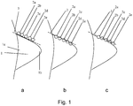
- Figure 1a to 1c show a schematic representation of a woman's breast 1 with four massaging protrusions 2a,2b,2c,2d performing three subsequent steps of a combing motion.
- An actuator (not shown) drives the four massaging protrusions 2a,2b,2c,2d.
- the massaging protrusions 2a,2b,2c,2d perform an effectively linear movement onto the skin of the woman's breast 1.
- a support plane 3 extends substantially parallel to the skin of the user's breast 1 .
- a support surface (not shown) is part of the breast massager (10,20,30; shown in Figures 2 to 4 ) and lies in the support plain 3 and contacts the skin of the breast 1 beneath the breast massager (10,20,30; shown in Figures 2 to 4 ).
- the massaging protrusions 2a,2b,2c,2d are linearly arranged parallel to the support plane 3 and the actuator (not shown) is arranged to drive the massaging protrusions 2a,2b,2c,2d in a circular or elliptical motion in a plane coinciding with the linear arrangement of the massaging protrusions 2a,2b,2c,2d and perpendicular to support surface (not shown) of the support plane 3.
- the massaging protrusions 2a,2b,2c,2d are arranged to extend through the support surface (not shown) of the support plane 3 by a varying amount during the circular or elliptical motion.
- the massaging protrusions 2a,2b,2c,2d touch onto the skin of the breast 1, but do not execute a pressure onto the breast 1.
- the actuator (not shown) will carry through the circular motion and force the protrusions 12 to pass through the support plane 3 and push the massaging protrusions 2a,2b,2c,2d onto the breast 1, as shown in Figure 1b , thereby creating local areas of increased pressure.
- the massaging protrusions will continue the circular or elliptical motion, as shown in Figure 1c , and relieve the pressure onto the breast 1.
- the massaging protrusions 2a,2b,2c,2d will complete the circular or elliptical movement and will return to the start position shown in Figure 1a .
- the direction of the massaging motion is in the direction from the base 1a of the breast 1 towards the nipple 1b: the circular motion executed by the protrusions moves the protrusions in this direction, while they extend through the support plane 3 and apply pressure to the breast 1. All embodiments of the invention perform a massaging motion to properly drain milk from the milk ducts.
- FIG. 2a to 2c show a first embodiment of a breast massager 10 according to the invention.
- the first breast massager 10 comprises a housing 11.
- the housing 11 is for holding the breast massager in the hand.
- the housing 11 may be designed for a comfortable user experience, for example by means of shape, material use and texture.
- the housing comprises a crankshaft 13, which is rotatably fixed at one end to the housing 11.
- the crankshaft 13 is coupled to a stiff beam 15 at the drive end of the crankshaft 13.
- the drive end of the crankshaft 13 comprises a pin 14 which is arranged to connect to the stiff beam 15.
- the stiff beam is connected to a number of massaging protrusions 12.
- the massaging protrusions 12 may vary among others in size and in arrangement with respect to the support surface (not shown) of the support plane 3.
- the stiff beam 15 and the massaging protrusions 12 may be integrally formed, but may also be connected to each other directly or indirectly, e.g. by a male-female connector.
- the housing comprises an actuator (not shown) for rotating the crankshaft 13.
- a second crankshaft (not shown) is connected to the stiff beam 15 at another position to perform a stable motion of the massaging protrusions 12.
- the second crankshaft (not shown) may be also be driven by the actuator (not shown) or may follow the motion of the crankshaft 13, effectively ensuring that the stiff beam performs a uniform circular motion in a plane perpendicular to the support plane 3.
- Figure 2a shows a starting position of the combing cycle.
- the stiff beam 15 and the massaging protrusions 12 are in a position in which the massaging protrusions are at the farthest distance from the breast 1, i.e. retracted away from the breast 1. In this position the protrusions 12 do not extend through the support plane 3.
- the actuator (not shown) drives the crankshaft 13 to perform a circular motion in the direction of arrow R. During the circular motion the massaging protrusions 12 pass through the support surface (not shown) of the support plane 3.
- Figure 2b shows the crankshaft 13 is in the opposite tangential position of the position of Figure 2a and, consequently, the stiff beam 15 and the massaging protrusions 12 in the extended position now touching the breast.
- the protrusions 12 are at their extended position through the support plane 3. In this position the massaging protrusions exert the highest pressure at local areas of the breast 1. Subsequently the crankshaft continues to rotate further in the direction R, as shown in Figure 2c , and the massaging protrusions 12 retract away from the breast 1, thus reducing the increased pressure at the local areas of the breast 1. Then the massaging protrusions 12 move further from the breast 1 and further into the housing and in the direction of the first position as shown in Figure 2a . The circular motion of the crankshaft 15 is thus transferred into a circular motion of the massaging protrusions 12 in a plane perpendicular to the support plane 3. The massaging protrusions 12 slide over the skin of the breast 1. In this way a user can execute a combing motion on a woman's breast 1.
- FIG. 3 shows a second embodiment of a breast massager 20 according to the invention.
- This embodiment will further be referred to as the second breast massager 20.
- the second breast massager 20 comprises a housing (not shown).
- the housing (not shown) is for holding the breast massager 20 in the hand.
- the housing (not shown) may be designed for a comfortable user experience, for example by means of shape, material use and texture.
- the breast massager 20 further comprises a number of massaging protrusions 22,23 which are each arranged to rotate around a pin (not shown) by means of a number of gear wheels 24,25,26, an actuator 28 and a transmission 29.
- the actuator 28 is arranged to drive the first gear wheel 24, the first gear wheel 24 transmits the rotational motion to the intermediate gear wheel 26.
- the intermediate gear wheel 26 is not coupled to a massaging protrusion 22,23.
- the intermediate gear wheel 26 consequently drives the second gear wheel 25.
- a first massaging protrusion 22 is coupled to the first gear wheel 24 and a second massaging protrusion 23 is coupled to the second protrusion 23.
- Rotation of the first gear wheel 24 causes the first protrusion 22 to perform a circular or elliptical motion in a plane perpendicular to the support plane 3 and coinciding with the linear arrangement of the massaging protrusions 22,23, while the second gear wheel 25 causes the second protrusion 23 to perform a circular or elliptical motion in the same plane as the first protrusion 22.
- the massaging protrusions 22,23 perform a circular or elliptical motion in a plane coinciding with the linear arrangement of the massaging protrusions 22,23 and perpendicular to a support surface 31 of the support plane 3.
- the massaging protrusions 22,23 are arranged to extend through a support surface 31 of the support plane 3 by an amount varying during the circular or elliptical motion.
- the protrusions 22,23 may start to extend through a support surface 31 of the support plane 3 at a different phase angle.
- the massaging protrusions 22,23 are thus oriented such that a local area of increased pressure, created by the movement of a massaging protrusion 22,23 perpendicular to a support surface 31 of the support plane 3, arises after a neighbouring local area of increased pressure.
- the massaging protrusions 22,23 are thus phase shiftedly arranged. In this way the local areas of increased pressure create a sequence or wave of increased pressure that passes along the plane such that the massaging protrusions perform a special version of a combing motion: a peristaltic motion.
- a peristaltic motion When the protrusions 22,23 extend at the same time, i.e. no phase differences between the protrusions, a regular combing motion is obtained.
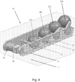
- FIG. 4 shows a third embodiment of a breast massager 30 according to the invention.
- This embodiment will further be referred to as the third breast massager 30.
- the third breast massager 30 comprises a housing (not shown).
- the housing (not shown) is for holding the breast massager 30 in the hand.
- the housing (not shown) may be designed for a comfortable user experience, for example by means of shape, material use and texture.
- the breast massager 30 further comprises a number of massaging protrusions 22,23 which are each arranged to rotate around a pin (not shown) by means of a gear belt 27, a number of gear wheels 24,25,26, an actuator 28 and a transmission 29.
- the actuator 28 is arranged to drive the gear belt 27.
- the first gear wheel 24 is coupled to the gear belt 27.
- the first gear wheel 24 is driven by the gear belt 27.
- the gear belt 27 is coupled to the second gear wheel 25 as well and drives the second gear wheel 25.
- a first massaging protrusion 22 is coupled to the first gear wheel 24 and a second massaging protrusion 23 is coupled to the second gear wheel 25.
- the first gear wheel 24 drives the circular or elliptical motion of the first protrusion 22, while the second gear wheel 25 drives the circular or elliptical motion of the second protrusion 23. Because the first gear wheel 24 is coupled to the first protrusion 22, the second gear wheel 25 is coupled to the second protrusion 23 and the actuator 28 is arranged to drive the gear belt 27 and the gear belt 27 drives the first and gear wheels 24,25, the massaging protrusions 22,23 are driven by the actuator 28.
- the massaging protrusions 22,23 perform a circular or elliptical motion in a plane coinciding with the linear arrangement of the massaging protrusions 22,23 and perpendicular to a support surface 31 of the support plane 3.
- the massaging protrusions 22,23 can be arranged to extend through the support plane 3 by an amount varying during the circular or elliptical motion.
- the protrusions 22,23 may start to extend through a support surface 31bof the support plane 3 at a different phase angle.
- the massaging protrusions 22,23 are thus oriented such that a local area of increased pressure, created by the movement of one of the second massaging protrusion 23 perpendicular to the a support surface 31 of support plane 3, arises after a neighbouring local area of increased pressure caused by the first protrusion 22.
- the massaging protrusions 22,23 are thus phase shiftedly arranged. In this way the local areas of increased pressure create a sequence or wave of increased pressure that passes along the plane such that the massaging protrusions perform a special version of a combing motion: a peristaltic movement.
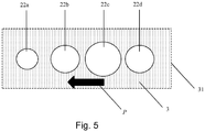
- Figure 5 shows a bottom view of the support plane 3 where the massaging protrusions 22,23 extend through the support surface 31 of the support plane 3 during their circular or elliptical motion.
- the massaging protrusions 22,23 are coupled to the first and the second gear wheel (not shown) each at a different phase angle. In this way the extension of each massaging protrusion 22,23 through the support plane 3 is different.
- the larger the view of massaging protrusion 22,23 the further the extension through the support plane 3.
- a peristaltic motion is performed, which, when applied in the right direction, stimulates the milk in the milk duct to flow towards the outlet of the milk duct at the nipple and properly drain the milk duct.
- the arrow P shows the direction of the peristaltic motion.
- the massaging protrusions 12,22,23 can be covered with a sleeve (not shown) made of plastic, rubber, silicone or the like.
- the massaging protrusions 12,22,23 can be covered individually or all together in one single sleeve (not shown).
- the sleeve (not shown) enables easy cleanability of the breast massager 10,20,30 and the massaging protrusions 12,22,23 in particular. Easy cleanability is beneficial for hygienic use of the breast massager 10,20,30.
- silicone and rubber are materials that adopt the temperature of the environment, in this particular situation the skin temperature, and have a skin-like texture, thus enabling the mother with a comfortable breast massaging experience.
- the breast massager 10,20,30 When the breast massager 10,20,30 is oriented such that the local areas of increased pressure move in the direction from the base 1a of the breast 1 towards the nipple 1b the milk in the milk ducts is stimulated towards the nipple 1b and the milk ducts will drain properly.
- a breast massager 10,20,30 may also comprise a different number of protrusions 12,22a, 22b, 22c, 22d such as 2, 3, 6, 7, 8.
Landscapes
- Health & Medical Sciences (AREA)
- Epidemiology (AREA)
- Pain & Pain Management (AREA)
- Physical Education & Sports Medicine (AREA)
- Rehabilitation Therapy (AREA)
- Life Sciences & Earth Sciences (AREA)
- Animal Behavior & Ethology (AREA)
- General Health & Medical Sciences (AREA)
- Public Health (AREA)
- Veterinary Medicine (AREA)
- Dermatology (AREA)
- Massaging Devices (AREA)
- Percussion Or Vibration Massage (AREA)
Applications Claiming Priority (2)
| Application Number | Priority Date | Filing Date | Title |
|---|---|---|---|
| CN2014071227 | 2014-01-23 | ||
| PCT/IB2015/050519 WO2015110998A1 (en) | 2014-01-23 | 2015-01-23 | A breast massager |
Publications (2)
| Publication Number | Publication Date |
|---|---|
| EP3096731A1 EP3096731A1 (en) | 2016-11-30 |
| EP3096731B1 true EP3096731B1 (en) | 2017-10-18 |
Family
ID=52629624
Family Applications (1)
| Application Number | Title | Priority Date | Filing Date |
|---|---|---|---|
| EP15708284.3A Not-in-force EP3096731B1 (en) | 2014-01-23 | 2015-01-23 | A breast massager |
Country Status (6)
| Country | Link |
|---|---|
| US (1) | US20160331627A1 (OSRAM) |
| EP (1) | EP3096731B1 (OSRAM) |
| JP (1) | JP2017503613A (OSRAM) |
| CN (1) | CN106102683A (OSRAM) |
| RU (1) | RU2016133992A (OSRAM) |
| WO (1) | WO2015110998A1 (OSRAM) |
Families Citing this family (6)
| Publication number | Priority date | Publication date | Assignee | Title |
|---|---|---|---|---|
| WO2018114637A1 (en) * | 2016-12-19 | 2018-06-28 | Koninklijke Philips N.V. | Breast pump apparatus |
| CN108309727A (zh) * | 2018-03-06 | 2018-07-24 | 谷昌德 | 乳腺疏通结构 |
| EP3829517A4 (en) * | 2018-08-01 | 2022-05-04 | Lactamo Holdings Pty Ltd | LACTATION AND BREAST TISSUE THERAPY DEVICE |
| CN110339041B (zh) * | 2019-06-11 | 2021-05-04 | 中国人民解放军陆军军医大学第一附属医院 | 一种乳腺按摩疏通装置 |
| CN113101435B (zh) * | 2021-04-14 | 2023-12-01 | 常州杜特电子科技有限公司 | 一种哺乳期用穿戴式可调节按摩吸奶器 |
| CN114931496B (zh) * | 2022-06-15 | 2025-05-16 | 深圳市司沃康科技有限公司 | 按摩器 |
Family Cites Families (16)
| Publication number | Priority date | Publication date | Assignee | Title |
|---|---|---|---|---|
| US3523524A (en) * | 1968-01-18 | 1970-08-11 | William B Wilson | Massage table with rollers |
| US3592188A (en) * | 1969-03-21 | 1971-07-13 | Forest H Barnett | Power operated gum massager and tooth brush |
| US4154232A (en) * | 1977-09-14 | 1979-05-15 | Syouji Fukazawa | Massager |
| CH653547A5 (fr) | 1983-07-26 | 1986-01-15 | Hubert Rutsch | Dispositif de massage. |
| CN2179755Y (zh) * | 1993-11-04 | 1994-10-19 | 赵常林 | 仿真健乳催乳器 |
| US6032313A (en) * | 1995-05-26 | 2000-03-07 | Tsang; Koon Keung | Household appliance having plural coaxially rotatable or parallel linearly movable heads or tools |
| CN2347591Y (zh) * | 1998-01-06 | 1999-11-10 | 苏原 | 机械手丰乳器 |
| US6500135B2 (en) * | 1998-12-31 | 2002-12-31 | Homedics, Inc. | Percussive massager |
| EP1261307A1 (en) * | 1999-12-15 | 2002-12-04 | Tensor Technologies, LLC | Massage device |
| US7238163B1 (en) * | 2002-06-25 | 2007-07-03 | Scott Fried | Treatment device for hand and wrist ailments |
| US6860861B2 (en) * | 2003-01-07 | 2005-03-01 | Gus Polychronis | Rotating apparatus for surface massage |
| CN100553602C (zh) * | 2005-05-10 | 2009-10-28 | 王伟 | 文胸式乳房仿真按摩器 |
| CN101099709B (zh) * | 2006-07-07 | 2010-08-18 | 薛增亮 | 乳房按摩器 |
| JP4774374B2 (ja) * | 2007-01-29 | 2011-09-14 | ピジョン株式会社 | 搾乳装置 |
| EP2172236A1 (en) * | 2008-10-03 | 2010-04-07 | Koninklijke Philips Electronics N.V. | Breast pump system |
| US9649247B2 (en) * | 2014-08-28 | 2017-05-16 | Ming-Wei Tsai | Massage device for breasts |
-
2015
- 2015-01-23 RU RU2016133992A patent/RU2016133992A/ru not_active Application Discontinuation
- 2015-01-23 US US15/111,045 patent/US20160331627A1/en not_active Abandoned
- 2015-01-23 EP EP15708284.3A patent/EP3096731B1/en not_active Not-in-force
- 2015-01-23 CN CN201580005614.1A patent/CN106102683A/zh active Pending
- 2015-01-23 WO PCT/IB2015/050519 patent/WO2015110998A1/en not_active Ceased
- 2015-01-23 JP JP2016548164A patent/JP2017503613A/ja active Pending
Non-Patent Citations (1)
| Title |
|---|
| None * |
Also Published As
| Publication number | Publication date |
|---|---|
| RU2016133992A3 (OSRAM) | 2018-08-10 |
| CN106102683A (zh) | 2016-11-09 |
| WO2015110998A1 (en) | 2015-07-30 |
| US20160331627A1 (en) | 2016-11-17 |
| EP3096731A1 (en) | 2016-11-30 |
| RU2016133992A (ru) | 2018-03-05 |
| JP2017503613A (ja) | 2017-02-02 |
Similar Documents
| Publication | Publication Date | Title |
|---|---|---|
| US20160331627A1 (en) | A breast massager | |
| US12161598B1 (en) | Sex toy | |
| US6056709A (en) | Portable massage device | |
| CN106618992B (zh) | 头部按摩器 | |
| CN103417364B (zh) | 多功能仿人按摩器 | |
| CN106943299B (zh) | 一种多功能组合式脚底按摩机构 | |
| CN103584983B (zh) | 一种按压、揉捏式肩颈部按摩器 | |
| US12458562B2 (en) | Sex toy | |
| CN103816033A (zh) | 眼睑按摩器 | |
| KR101345771B1 (ko) | 단일 구동부로 넓은 면적의 안마가 가능한 안마장치 | |
| CN106619063A (zh) | 一种具有多种按摩方式的按摩装置 | |
| JP3187608U (ja) | 按摩器 | |
| CN106420331A (zh) | 一种多样式的自动按摩设备 | |
| US6196984B1 (en) | Portable message device | |
| TWM497527U (zh) | 一種按摩器 | |
| CN106333833B (zh) | 仿生按摩手 | |
| CN104414835B (zh) | 按摩机 | |
| KR101398011B1 (ko) | 휴대용 다기능 마사지 기구 | |
| JP6137448B2 (ja) | 指間用指圧装置 | |
| CN203315296U (zh) | 一种辅助腱鞘炎自我康复的按摩装置 | |
| CN103330638B (zh) | 一种辅助腱鞘炎自我康复的按摩装置及其使用方法 | |
| WO2017084230A1 (zh) | 走珠按摩器 | |
| KR101424204B1 (ko) | 휴대용 다기능 마사지 기구 | |
| CN219896324U (zh) | 肩颈按摩仪 | |
| JP2015084777A (ja) | 美容機器 |
Legal Events
| Date | Code | Title | Description |
|---|---|---|---|
| PUAI | Public reference made under article 153(3) epc to a published international application that has entered the european phase |
Free format text: ORIGINAL CODE: 0009012 |
|
| 17P | Request for examination filed |
Effective date: 20160823 |
|
| AK | Designated contracting states |
Kind code of ref document: A1 Designated state(s): AL AT BE BG CH CY CZ DE DK EE ES FI FR GB GR HR HU IE IS IT LI LT LU LV MC MK MT NL NO PL PT RO RS SE SI SK SM TR |
|
| AX | Request for extension of the european patent |
Extension state: BA ME |
|
| DAX | Request for extension of the european patent (deleted) | ||
| GRAP | Despatch of communication of intention to grant a patent |
Free format text: ORIGINAL CODE: EPIDOSNIGR1 |
|
| INTG | Intention to grant announced |
Effective date: 20170511 |
|
| GRAS | Grant fee paid |
Free format text: ORIGINAL CODE: EPIDOSNIGR3 |
|
| GRAA | (expected) grant |
Free format text: ORIGINAL CODE: 0009210 |
|
| AK | Designated contracting states |
Kind code of ref document: B1 Designated state(s): AL AT BE BG CH CY CZ DE DK EE ES FI FR GB GR HR HU IE IS IT LI LT LU LV MC MK MT NL NO PL PT RO RS SE SI SK SM TR |
|
| REG | Reference to a national code |
Ref country code: GB Ref legal event code: FG4D |
|
| REG | Reference to a national code |
Ref country code: CH Ref legal event code: EP |
|
| REG | Reference to a national code |
Ref country code: AT Ref legal event code: REF Ref document number: 937298 Country of ref document: AT Kind code of ref document: T Effective date: 20171115 Ref country code: IE Ref legal event code: FG4D |
|
| REG | Reference to a national code |
Ref country code: DE Ref legal event code: R096 Ref document number: 602015005464 Country of ref document: DE |
|
| REG | Reference to a national code |
Ref country code: FR Ref legal event code: PLFP Year of fee payment: 4 |
|
| REG | Reference to a national code |
Ref country code: NL Ref legal event code: MP Effective date: 20171018 |
|
| REG | Reference to a national code |
Ref country code: LT Ref legal event code: MG4D |
|
| REG | Reference to a national code |
Ref country code: AT Ref legal event code: MK05 Ref document number: 937298 Country of ref document: AT Kind code of ref document: T Effective date: 20171018 |
|
| PG25 | Lapsed in a contracting state [announced via postgrant information from national office to epo] |
Ref country code: NL Free format text: LAPSE BECAUSE OF FAILURE TO SUBMIT A TRANSLATION OF THE DESCRIPTION OR TO PAY THE FEE WITHIN THE PRESCRIBED TIME-LIMIT Effective date: 20171018 |
|
| PG25 | Lapsed in a contracting state [announced via postgrant information from national office to epo] |
Ref country code: ES Free format text: LAPSE BECAUSE OF FAILURE TO SUBMIT A TRANSLATION OF THE DESCRIPTION OR TO PAY THE FEE WITHIN THE PRESCRIBED TIME-LIMIT Effective date: 20171018 Ref country code: LT Free format text: LAPSE BECAUSE OF FAILURE TO SUBMIT A TRANSLATION OF THE DESCRIPTION OR TO PAY THE FEE WITHIN THE PRESCRIBED TIME-LIMIT Effective date: 20171018 Ref country code: FI Free format text: LAPSE BECAUSE OF FAILURE TO SUBMIT A TRANSLATION OF THE DESCRIPTION OR TO PAY THE FEE WITHIN THE PRESCRIBED TIME-LIMIT Effective date: 20171018 Ref country code: SE Free format text: LAPSE BECAUSE OF FAILURE TO SUBMIT A TRANSLATION OF THE DESCRIPTION OR TO PAY THE FEE WITHIN THE PRESCRIBED TIME-LIMIT Effective date: 20171018 Ref country code: NO Free format text: LAPSE BECAUSE OF FAILURE TO SUBMIT A TRANSLATION OF THE DESCRIPTION OR TO PAY THE FEE WITHIN THE PRESCRIBED TIME-LIMIT Effective date: 20180118 |
|
| PG25 | Lapsed in a contracting state [announced via postgrant information from national office to epo] |
Ref country code: HR Free format text: LAPSE BECAUSE OF FAILURE TO SUBMIT A TRANSLATION OF THE DESCRIPTION OR TO PAY THE FEE WITHIN THE PRESCRIBED TIME-LIMIT Effective date: 20171018 Ref country code: IS Free format text: LAPSE BECAUSE OF FAILURE TO SUBMIT A TRANSLATION OF THE DESCRIPTION OR TO PAY THE FEE WITHIN THE PRESCRIBED TIME-LIMIT Effective date: 20180218 Ref country code: GR Free format text: LAPSE BECAUSE OF FAILURE TO SUBMIT A TRANSLATION OF THE DESCRIPTION OR TO PAY THE FEE WITHIN THE PRESCRIBED TIME-LIMIT Effective date: 20180119 Ref country code: AT Free format text: LAPSE BECAUSE OF FAILURE TO SUBMIT A TRANSLATION OF THE DESCRIPTION OR TO PAY THE FEE WITHIN THE PRESCRIBED TIME-LIMIT Effective date: 20171018 Ref country code: LV Free format text: LAPSE BECAUSE OF FAILURE TO SUBMIT A TRANSLATION OF THE DESCRIPTION OR TO PAY THE FEE WITHIN THE PRESCRIBED TIME-LIMIT Effective date: 20171018 Ref country code: RS Free format text: LAPSE BECAUSE OF FAILURE TO SUBMIT A TRANSLATION OF THE DESCRIPTION OR TO PAY THE FEE WITHIN THE PRESCRIBED TIME-LIMIT Effective date: 20171018 Ref country code: BG Free format text: LAPSE BECAUSE OF FAILURE TO SUBMIT A TRANSLATION OF THE DESCRIPTION OR TO PAY THE FEE WITHIN THE PRESCRIBED TIME-LIMIT Effective date: 20180118 |
|
| PGFP | Annual fee paid to national office [announced via postgrant information from national office to epo] |
Ref country code: TR Payment date: 20180119 Year of fee payment: 4 Ref country code: FR Payment date: 20180125 Year of fee payment: 4 |
|
| REG | Reference to a national code |
Ref country code: DE Ref legal event code: R097 Ref document number: 602015005464 Country of ref document: DE |
|
| PG25 | Lapsed in a contracting state [announced via postgrant information from national office to epo] |
Ref country code: CZ Free format text: LAPSE BECAUSE OF FAILURE TO SUBMIT A TRANSLATION OF THE DESCRIPTION OR TO PAY THE FEE WITHIN THE PRESCRIBED TIME-LIMIT Effective date: 20171018 Ref country code: EE Free format text: LAPSE BECAUSE OF FAILURE TO SUBMIT A TRANSLATION OF THE DESCRIPTION OR TO PAY THE FEE WITHIN THE PRESCRIBED TIME-LIMIT Effective date: 20171018 Ref country code: SK Free format text: LAPSE BECAUSE OF FAILURE TO SUBMIT A TRANSLATION OF THE DESCRIPTION OR TO PAY THE FEE WITHIN THE PRESCRIBED TIME-LIMIT Effective date: 20171018 Ref country code: DK Free format text: LAPSE BECAUSE OF FAILURE TO SUBMIT A TRANSLATION OF THE DESCRIPTION OR TO PAY THE FEE WITHIN THE PRESCRIBED TIME-LIMIT Effective date: 20171018 |
|
| PGFP | Annual fee paid to national office [announced via postgrant information from national office to epo] |
Ref country code: DE Payment date: 20180329 Year of fee payment: 4 |
|
| PLBE | No opposition filed within time limit |
Free format text: ORIGINAL CODE: 0009261 |
|
| STAA | Information on the status of an ep patent application or granted ep patent |
Free format text: STATUS: NO OPPOSITION FILED WITHIN TIME LIMIT |
|
| PG25 | Lapsed in a contracting state [announced via postgrant information from national office to epo] |
Ref country code: RO Free format text: LAPSE BECAUSE OF FAILURE TO SUBMIT A TRANSLATION OF THE DESCRIPTION OR TO PAY THE FEE WITHIN THE PRESCRIBED TIME-LIMIT Effective date: 20171018 Ref country code: SM Free format text: LAPSE BECAUSE OF FAILURE TO SUBMIT A TRANSLATION OF THE DESCRIPTION OR TO PAY THE FEE WITHIN THE PRESCRIBED TIME-LIMIT Effective date: 20171018 Ref country code: PL Free format text: LAPSE BECAUSE OF FAILURE TO SUBMIT A TRANSLATION OF THE DESCRIPTION OR TO PAY THE FEE WITHIN THE PRESCRIBED TIME-LIMIT Effective date: 20171018 Ref country code: IT Free format text: LAPSE BECAUSE OF FAILURE TO SUBMIT A TRANSLATION OF THE DESCRIPTION OR TO PAY THE FEE WITHIN THE PRESCRIBED TIME-LIMIT Effective date: 20171018 |
|
| REG | Reference to a national code |
Ref country code: CH Ref legal event code: PL |
|
| 26N | No opposition filed |
Effective date: 20180719 |
|
| PG25 | Lapsed in a contracting state [announced via postgrant information from national office to epo] |
Ref country code: LU Free format text: LAPSE BECAUSE OF NON-PAYMENT OF DUE FEES Effective date: 20180123 |
|
| REG | Reference to a national code |
Ref country code: IE Ref legal event code: MM4A |
|
| REG | Reference to a national code |
Ref country code: BE Ref legal event code: MM Effective date: 20180131 |
|
| PG25 | Lapsed in a contracting state [announced via postgrant information from national office to epo] |
Ref country code: LI Free format text: LAPSE BECAUSE OF NON-PAYMENT OF DUE FEES Effective date: 20180131 Ref country code: BE Free format text: LAPSE BECAUSE OF NON-PAYMENT OF DUE FEES Effective date: 20180131 Ref country code: SI Free format text: LAPSE BECAUSE OF FAILURE TO SUBMIT A TRANSLATION OF THE DESCRIPTION OR TO PAY THE FEE WITHIN THE PRESCRIBED TIME-LIMIT Effective date: 20171018 Ref country code: CH Free format text: LAPSE BECAUSE OF NON-PAYMENT OF DUE FEES Effective date: 20180131 |
|
| PG25 | Lapsed in a contracting state [announced via postgrant information from national office to epo] |
Ref country code: IE Free format text: LAPSE BECAUSE OF NON-PAYMENT OF DUE FEES Effective date: 20180123 |
|
| PG25 | Lapsed in a contracting state [announced via postgrant information from national office to epo] |
Ref country code: MC Free format text: LAPSE BECAUSE OF FAILURE TO SUBMIT A TRANSLATION OF THE DESCRIPTION OR TO PAY THE FEE WITHIN THE PRESCRIBED TIME-LIMIT Effective date: 20171018 |
|
| REG | Reference to a national code |
Ref country code: DE Ref legal event code: R119 Ref document number: 602015005464 Country of ref document: DE |
|
| GBPC | Gb: european patent ceased through non-payment of renewal fee |
Effective date: 20190123 |
|
| PG25 | Lapsed in a contracting state [announced via postgrant information from national office to epo] |
Ref country code: DE Free format text: LAPSE BECAUSE OF NON-PAYMENT OF DUE FEES Effective date: 20190801 Ref country code: FR Free format text: LAPSE BECAUSE OF NON-PAYMENT OF DUE FEES Effective date: 20190131 |
|
| PG25 | Lapsed in a contracting state [announced via postgrant information from national office to epo] |
Ref country code: GB Free format text: LAPSE BECAUSE OF NON-PAYMENT OF DUE FEES Effective date: 20190123 |
|
| PG25 | Lapsed in a contracting state [announced via postgrant information from national office to epo] |
Ref country code: MT Free format text: LAPSE BECAUSE OF NON-PAYMENT OF DUE FEES Effective date: 20180123 |
|
| PG25 | Lapsed in a contracting state [announced via postgrant information from national office to epo] |
Ref country code: PT Free format text: LAPSE BECAUSE OF FAILURE TO SUBMIT A TRANSLATION OF THE DESCRIPTION OR TO PAY THE FEE WITHIN THE PRESCRIBED TIME-LIMIT Effective date: 20171018 |
|
| PG25 | Lapsed in a contracting state [announced via postgrant information from national office to epo] |
Ref country code: MK Free format text: LAPSE BECAUSE OF NON-PAYMENT OF DUE FEES Effective date: 20171018 Ref country code: CY Free format text: LAPSE BECAUSE OF FAILURE TO SUBMIT A TRANSLATION OF THE DESCRIPTION OR TO PAY THE FEE WITHIN THE PRESCRIBED TIME-LIMIT Effective date: 20171018 Ref country code: HU Free format text: LAPSE BECAUSE OF FAILURE TO SUBMIT A TRANSLATION OF THE DESCRIPTION OR TO PAY THE FEE WITHIN THE PRESCRIBED TIME-LIMIT; INVALID AB INITIO Effective date: 20150123 |
|
| PG25 | Lapsed in a contracting state [announced via postgrant information from national office to epo] |
Ref country code: AL Free format text: LAPSE BECAUSE OF FAILURE TO SUBMIT A TRANSLATION OF THE DESCRIPTION OR TO PAY THE FEE WITHIN THE PRESCRIBED TIME-LIMIT Effective date: 20171018 |
|
| PG25 | Lapsed in a contracting state [announced via postgrant information from national office to epo] |
Ref country code: TR Free format text: LAPSE BECAUSE OF NON-PAYMENT OF DUE FEES Effective date: 20190123 |