EP3096704B1 - Drap stérile et adaptateur pour recouvrir un bras chirurgical robotique et empêcher la contamination de champ stérile - Google Patents
Drap stérile et adaptateur pour recouvrir un bras chirurgical robotique et empêcher la contamination de champ stérile Download PDFInfo
- Publication number
- EP3096704B1 EP3096704B1 EP15700759.2A EP15700759A EP3096704B1 EP 3096704 B1 EP3096704 B1 EP 3096704B1 EP 15700759 A EP15700759 A EP 15700759A EP 3096704 B1 EP3096704 B1 EP 3096704B1
- Authority
- EP
- European Patent Office
- Prior art keywords
- sterile
- drape
- sterile drape
- surgical
- robotic arm
- Prior art date
- Legal status (The legal status is an assumption and is not a legal conclusion. Google has not performed a legal analysis and makes no representation as to the accuracy of the status listed.)
- Active
Links
- 238000011109 contamination Methods 0.000 title claims description 12
- 239000003351 stiffener Substances 0.000 claims description 24
- 239000002390 adhesive tape Substances 0.000 claims description 16
- 239000000463 material Substances 0.000 claims description 8
- 239000004033 plastic Substances 0.000 claims description 7
- 230000002787 reinforcement Effects 0.000 claims description 3
- 238000000034 method Methods 0.000 description 33
- 238000001356 surgical procedure Methods 0.000 description 26
- 238000005516 engineering process Methods 0.000 description 14
- 239000012636 effector Substances 0.000 description 8
- 230000001629 suppression Effects 0.000 description 8
- 230000001954 sterilising effect Effects 0.000 description 7
- 238000004659 sterilization and disinfection Methods 0.000 description 7
- 238000002591 computed tomography Methods 0.000 description 4
- 239000000428 dust Substances 0.000 description 4
- 238000002594 fluoroscopy Methods 0.000 description 4
- 230000000087 stabilizing effect Effects 0.000 description 4
- 239000000853 adhesive Substances 0.000 description 3
- 230000001070 adhesive effect Effects 0.000 description 3
- 239000002131 composite material Substances 0.000 description 3
- 238000005553 drilling Methods 0.000 description 3
- 239000003550 marker Substances 0.000 description 3
- 230000003287 optical effect Effects 0.000 description 3
- 229920000642 polymer Polymers 0.000 description 3
- 238000002360 preparation method Methods 0.000 description 3
- 238000003466 welding Methods 0.000 description 3
- 210000000988 bone and bone Anatomy 0.000 description 2
- 239000003292 glue Substances 0.000 description 2
- 238000002324 minimally invasive surgery Methods 0.000 description 2
- 239000012811 non-conductive material Substances 0.000 description 2
- 238000012549 training Methods 0.000 description 2
- 208000008558 Osteophyte Diseases 0.000 description 1
- 206010044565 Tremor Diseases 0.000 description 1
- 238000004026 adhesive bonding Methods 0.000 description 1
- 230000003466 anti-cipated effect Effects 0.000 description 1
- 210000001367 artery Anatomy 0.000 description 1
- 230000000903 blocking effect Effects 0.000 description 1
- 230000001419 dependent effect Effects 0.000 description 1
- 238000013461 design Methods 0.000 description 1
- 230000004927 fusion Effects 0.000 description 1
- 238000009434 installation Methods 0.000 description 1
- 239000012212 insulator Substances 0.000 description 1
- 238000002684 laminectomy Methods 0.000 description 1
- 230000007257 malfunction Effects 0.000 description 1
- 238000004519 manufacturing process Methods 0.000 description 1
- 238000005259 measurement Methods 0.000 description 1
- 210000005036 nerve Anatomy 0.000 description 1
- 210000000056 organ Anatomy 0.000 description 1
- 238000012545 processing Methods 0.000 description 1
- 238000009877 rendering Methods 0.000 description 1
- 238000007789 sealing Methods 0.000 description 1
- 239000002356 single layer Substances 0.000 description 1
- 210000000278 spinal cord Anatomy 0.000 description 1
- 238000013519 translation Methods 0.000 description 1
- 230000014616 translation Effects 0.000 description 1
Images


Classifications
-
- A—HUMAN NECESSITIES
- A61—MEDICAL OR VETERINARY SCIENCE; HYGIENE
- A61B—DIAGNOSIS; SURGERY; IDENTIFICATION
- A61B46/00—Surgical drapes
- A61B46/20—Surgical drapes specially adapted for patients
- A61B46/27—Surgical drapes specially adapted for patients tubular, e.g. for arms or legs
-
- A—HUMAN NECESSITIES
- A61—MEDICAL OR VETERINARY SCIENCE; HYGIENE
- A61B—DIAGNOSIS; SURGERY; IDENTIFICATION
- A61B46/00—Surgical drapes
- A61B46/10—Surgical drapes specially adapted for instruments, e.g. microscopes
-
- A—HUMAN NECESSITIES
- A61—MEDICAL OR VETERINARY SCIENCE; HYGIENE
- A61B—DIAGNOSIS; SURGERY; IDENTIFICATION
- A61B34/00—Computer-aided surgery; Manipulators or robots specially adapted for use in surgery
- A61B34/30—Surgical robots
Definitions
- Robotic-assisted surgical systems have been developed to improve surgical precision and enable the implementation of new surgical procedures.
- robotic systems have been developed to sense a surgeon's hand movements and translate them to scaled-down micro-movements and filter out unintentional tremors for precise microsurgical techniques in organ transplants, reconstructions, and minimally invasive surgeries.
- Other robotic systems are directed to telemanipulation of surgical tools such that the surgeon does not have to be present in the operating room, thereby facilitating remote surgery.
- Feedback-controlled robotic systems have also been developed to provide smoother manipulation of a surgical tool during a procedure than could be achieved by an unaided surgeon.
- WO 2013/160239 A1 discloses a sterile drape for covering a surgical robot arm.
- US 4799779 A discloses a surgical drape for covering a microscope having side sleeves.
- Common spinal surgical procedures include a discectomy for removal of all or part of a disk, a foraminotomy for widening of the opening where nerve roots leave the spinal column, a laminectomy for removal of the lamina or bone spurs in the back, and spinal fusion for fusing of two vertebrae or vertebral segments together to eliminate pain caused by movement of the vertebrae.
- a surgeon judges a drill trajectory for subsequent screw placement on the basis of pre-operative CT scans.
- Other manual methods which do not involve usage of the pre-operative CT scans, such as fluoroscopy, 3D fluoroscopy or natural landmark-based, may be used to determine the trajectory for preparing holes in bone prior to placement of the screws.
- the surgeon holds the drill in his hand while drilling, and fluoroscopic images are obtained to verify if the trajectory is correct.
- Some surgical techniques involve usage of different tools, such as a pedicle finder or K-wires. Such procedures rely strongly on the expertise of the surgeon, and there is significant variation in success rate among different surgeons. Screw misplacement is a common problem in such surgical procedures.
- Image-guided spinal surgeries involve optical tracking to aid in screw placement.
- surgical tools can be inaccurately positioned despite virtual tracking.
- a surgeon is required to coordinate his real-world, manual manipulation of surgical tools using images displayed on a two dimensional screen.
- Such procedures can be non-intuitive and require training, since the surgeon's eye must constantly scan both the surgical site and the screen to confirm alignment.
- procedural error can result in registration inaccuracy of the image-guiding system, rendering it useless, or even misleading.
- Described herein are a sterile drape and adapter for use with a robotic surgical system, for example, during spinal surgery.
- the invention is defined by claim 1. Further embodiments of the invention are defined by the dependent claims.
- the sterile drape and adapter cover a robotic surgical arm and prevent contamination of a sterile field.
- the sterile drape may attached to the robotic arm via a sterile adapter that ensures the drape is tightly stretched over the tool holder and robot interface to provide a structure that provides for repeatable and rigid positioning of the sterile drape. Tightly stretching the drape over the sterile adapter and tightening the tool holder to the robotic arm using, for example, a tightening screw, reduces the likelihood of folds in the drape between the told holder and robot interface. Thus, errors caused by inaccurate positioning of the tool holder relative to the robot interface are minimized.
- a hermetically sealed zone is formed by the tool holder, sterile adapter, and robotic arm.
- the hermetically sealed zone contains the perforated sections of the sterile drape, thus ensuring the robotic system may be used in a sterile environment even after the tool support is attached to the robotic arm.
- the disclosed technology includes a sterile drape for covering a surgical robotic arm and preventing contamination of a sterile field.
- the sterile drape includes a flexible covering with a sterile outer surface. The covering may be at least partially conformable to a surgical robotic arm.
- the sterile drape may include an embedded connector configured (e.g., positioned on the flexible covering and sized) to permit electrical contact between the surgical robotic arm (e.g., an actuator of the robotic arm) and a sterile manipulator (e.g., sterile handle) of the robotic arm when the sterile manipulator is separated from the surgical robotic arm by the flexible covering.
- the sterile drape is disposable (e.g., a single-use product).
- the disclosed technology includes a rigid or semi-rigid sterile adapter (e.g., made from a hard plastic, a polymer, or a composite material) for securing a sterile drape over a surgical robotic arm to prevent contamination of a sterile field.
- the sterile adapter includes a rigid or semi-rigid collar (e.g., ring) configured to mount (e.g., snap-mount) onto an interface of the surgical robotic arm.
- the sterile adapter may include a rigid or semi-rigid body extending from the collar and shaped to conform to a portion of the surgical robotic arm to tightly secure a flexible drape in place (e.g., with no folds) over the portion of the surgical robotic arm when the drape is attached to the adapter.
- the sterile adapter is disposable (e.g. a single-use product).
- the disclosed technology includes a sterile drape that is attached (e.g., glued or welded) to a sterile adapter.
- the sterile adapter that ensures the drape is tightly stretched over the tool holder and robot interface to protect the robotic arm and mobile cart from contaminating the sterile field, and provides a structure that provides for repeatable and rigid positioning of the sterile drape.
- the disclosed technology includes a sterile drape for covering a surgical robotic arm and preventing contamination of a sterile field.
- the sterile drape includes, in certain embodiments, a flexible covering with a sterile outer surface and a sterile drape sleeve configured to receive an electrical plug therethrough, said covering being at least partially conformable to a surgical robotic arm.
- the sterile drape sleeve is configured to be sealed around a portion of the electrical plug using a sterile adhesive tape.
- the sterile drape sleeve in certain embodiments, is configured to surround at least a portion of a connector of the surgical robotic arm and extend outwardly from the connector.
- the connector is configured to permit electrical contact between the surgical robotic arm (e.g., an actuator of the robotic arm) and a sterile manipulator (e.g., sterile handle) of the robotic arm when the sterile manipulator is separated from the surgical robotic arm by the flexible covering.
- the surgical robotic arm e.g., an actuator of the robotic arm
- a sterile manipulator e.g., sterile handle
- the sterile drape is configured to be attached to the sterile drape before draping the robotic surgical arm.
- the connector is configured to receive the electrical plug after the electrical plug is passed through the sterile drape sleeve.
- the connector is configured to receive the electrical plug after (i) the electrical plug is passed through the sterile drape sleeve and (ii) the sterile drape sleeve is sealed around a portion of the electrical plug using a sterile adhesive tape.
- the sterile drape is configured to be attached to the sterile drape after draping the robotic surgical arm.
- the sterile drape comprises a drape stiffener configured to assist in passing the electrical plug through the sterile drape sleeve.
- the drape stiffener is made of a semi-rigid material (e.g., rubber, adhesive tape, tape reinforcement).
- the drape stiffener is made of a rigid material (e.g., plastic).
- the drape stiffener is integrated in the sterile drape.
- the drape stiffener is removable.
- the drape stiffener is configured to be inserted before the sterile drape is applied to the robot surgical arm.
- the drape stiffener is configured to be inserted after the sterile drape is applied to the robot surgical arm. In certain embodiments, the drape stiffener is configured to be removed after the sterile drape is applied to the robot surgical arm. In certain embodiments, the drape stiffener is configured to be removed after (i) the sterile drape is applied to the robot surgical arm and (ii) the sterile drape sleeve is sealed around a portion of the electrical plug using a sterile adhesive tape.
- the disclosed technology includes a sterile drape for covering a surgical robotic arm and preventing contamination of a sterile field.
- the sterile drape includes a flexible covering with a sterile outer surface, said covering being at least partially conformable to a surgical robotic arm.
- the flexible covering includes a drape opening that is configured to be contained within a sealed chamber formed by the surgical robotic arm, a sterile adapter, and a surgical tool holder such that a fastening system may pass through the chamber and the drape opening when the surgical instrument holder is coupled to the surgical robotic arm.
- the fastening system comprises one or more positioning elements that extend from the surgical robotic arm and engage one or more surgical instrument holder positioning members.
- the one or more positioning elements are one or more pegs.
- the one or more pegs are configured to extend from the robotic arm and engage one or more holes in the surgical instrument holder.
- the fastening system comprises a fastening member configured to securely attach the surgical instrument holder to the surgical robotic arm.
- the fastening member is a member selected from the group consisting of a bolt, nut, screw, and one or more electro magnets.
- the disclosed technology includes a sterile drape for covering a surgical robotic arm and preventing contamination of a sterile field.
- the sterile drape includes a flexible covering with a sterile outer surface, said covering being at least partially conformable to a surgical robotic arm; and an embedded connector configured (e.g., positioned on the flexible covering and sized) to permit electrical contact between the surgical robotic arm (e.g., an actuator of the robotic arm) and a sterile manipulator (e.g., sterile handle) of the robotic arm when the sterile manipulator is separated from the surgical robotic arm by the flexible covering.
- the surgical robotic arm e.g., an actuator of the robotic arm
- a sterile manipulator e.g., sterile handle
- the disclosed technology includes a rigid or semi-rigid sterile adapter (e.g., made from a hard plastic, a polymer, or a composite material) for securing a sterile drape over a surgical robotic arm to prevent contamination of a sterile field.
- a rigid or semi-rigid sterile adapter e.g., made from a hard plastic, a polymer, or a composite material
- the sterile adapter includes a rigid or semi-rigid collar (e.g., ring) configured to mount (e.g., snap-mount) onto an interface of the surgical robotic arm; and a rigid or semi-rigid body extending from the collar and shaped to conform to a portion of the surgical robotic arm to tightly secure a flexible drape in place (e.g., with no folds) over the portion of the surgical robotic arm when the drape is attached to the adapter.
- a rigid or semi-rigid collar e.g., ring
- mount e.g., snap-mount
- a rigid or semi-rigid body extending from the collar and shaped to conform to a portion of the surgical robotic arm to tightly secure a flexible drape in place (e.g., with no folds) over the portion of the surgical robotic arm when the drape is attached to the adapter.
- the sterile drape is disposable (e.g., a single-use product).
- the sterile adapter is disposable (e.g. a single-use product).
- the disclosed technology includes an apparatus that includes a sterile drape and a sterile adapter.
- the apparatus is disposable (e.g., a single-use product).
- the disclosed technology includes a robotic surgical system for performing surgery.
- the system includes a robotic arm with an end effector, a surgical instrument holder configured to securely hold the surgical instrument, and one or more positioning elements configured to provide accurate and repeatable positioning of the surgical instrument holder in reference to the robotic arm; a manipulator configured to allow robotically-assisted or unassisted positioning and/or movement of the surgical instrument by a user with at least four degrees of freedom to align an axis defined by the surgical instrument at a desired trajectory in relation to a patient situation; a sterile drape configured to protect the robotic arm from contaminating a sterile field.
- the sterile drape includes a drape connector configured to electrically couple, through the sterile drape, the manipulator to an electrical system of the robotic surgical system covered by the sterile drape, and the one or more positioning elements pass through the sterile drape.
- a sterile adapter is configured to attach to the robotic arm via a robotic interface and tightly stretch the sterile drape to assure repeatable and rigid positioning of the sterile drape.
- the surgical instrument holder is attached to the robotic arm using a fastening system configured to pass through the sterile adapter and the sterile drape.
- the surgical instrument comprises a surgical instrument guide configured to hold and/or restrict movement of a second surgical instrument there through.
- the second surgical instrument is a member selected from the group consisting of: a drill bit, tap, screw driver, and awl.
- the second surgical instrument is a drill bit and the surgical instrument guide is a drill guide.
- the robotic surgical system is for use in spinal surgery.
- the one or more positioning elements extend from the robotic arm and engage one or more surgical instrument holder positioning members. In certain embodiments, the one or more positioning elements are one or more pegs. In certain embodiments, the one or more pegs are configured to extend from the robotic arm and engage one or more holes in the surgical instrument holder. In certain embodiments, the one or more positioning elements are configured to pass through the sterile drape.
- the system includes a mobile cart configured to transport the robotic surgical system, wherein the sterile drape is configured to protect the mobile cart from contaminating a sterile field.
- the sterile drape comprises a first sterile drape to protect the robotic arm and a second sterile drape to protect the mobile cart.
- the sterile drape comprises printed marks configured to assist in proper draping procedure.
- the system includes one or more holding stripes configured to hold the sterile drape (e.g., securely in place). In certain embodiments, the one or more holding stripes secure a portion of the sterile drape to the robotic arm.
- the system includes a suppression system configured to remove air from under the sterile drape.
- the suppression system includes at least one member selected from the group consisting of a ventilator and a suction device that pumps out the air from under the sterile drape.
- the sterile handle is coupled to a handle connector via a cable and the handle connector is configured to electrically connect to the drape connector.
- the electrical system of the robotic surgical system is coupled to a robot connector and the robot connector is configured to electrically connect to the drape connector.
- the robot connector electrically couples the drape connector to the robot connector.
- the sterile adapter comprises one or more tabs configured to attach to the robotic arm.
- the one or more tabs click onto an interface on the robotic arm.
- the one or more tabs comprise four tabs.
- the sterile drape is glued or welded to the sterile adapter.
- the sterile drape passes between the surgical instrument tool holder and the robotic interface. In certain embodiments, the sterile drape is tightly stretched between the surgical instrument tool holder and the robotic interface. In certain embodiments, the surgical instrument holder is a non-conductive material.
- the disclosed technology includes an exemplary not claimed method of performing surgery with a robotic surgical system.
- the method includes attaching a sterile adapter to a robotic arm of a robotic surgical system via a robotic interface, wherein: a sterile drape is coupled to the sterile adapter and is configured to protect the robotic arm from contaminating a sterile field, and the sterile adapter is configured to tightly stretch the sterile drape to assure repeatable and rigid positioning of the sterile drape; covering a portion of the robotic surgical system with the sterile drape; connecting a drape connector to a handle connector and a robot connector, wherein the sterile drape comprises the drape connector and the drape connector is configured to electrically couple the handle connector to the robot connector; securing a portion of the sterile drape to the robotic arm via one or more holding stripes; attaching the surgical tool holder to the robotic arm using a fastening system configured to pass through the sterile adapter and the sterile drape, wherein: the surgical tool holder is
- the exemplary method includes maneuvering the second surgical instrument through the surgical instrument guide. In certain embodiments, the method includes maneuvering a drill bit through a drill bit guide.
- the sterile drape is configured to cover the robotic arm and mobile cart and protect the robotic arm and mobile cart from contaminating a sterile field.
- the fastening system goes through the sterile drape.
- the one or more holding stripes wrap around the robotic arm.
- a suppression system configured to remove air from under the sterile drape. In certain embodiments, the suppression system comprises at least one member selected from the group consisting of a ventilator and a suction device that pumps out the air from under the sterile drape.
- stabilizing the mobile cart includes extracting one or more rigid legs on the mobile cart such that the mobile cart rests on the one or more rigid legs of the mobile cart. In certain embodiments, stabilizing the mobile cart comprises retracting one or more wheels on the mobile cart such that the mobile cart rests on one or more rigid legs of the mobile cart.
- the method includes, prior to maneuvering the robotic arm to a desired position, obtaining or accessing a CT scan, 3D CT scan, fluoroscopy, 3D fluoroscopy, or natural landmark-based image of the patient situation.
- the desired trajectory is a desired path of the surgical tool.
- FIG. 1 illustrates an example robotic surgical system 100.
- one or more surgeons, surgical assistants, surgical technologists and/or other technicians perform an operation on a patient using a robotic-assisted surgical system 100.
- the robotic surgical system 100 may be transported in and out of an operating room using a mobile cart 104. Accordingly, the robotic surgical system 100, including the mobile cart 104, must be sterilized when used in the operating room.
- the system may be sterilized by applying a sterile drape 102 to a portion of the system 100, including at least part of the robotic arm 106 and the mobile cart 104.
- the sterile drape 102 may consist of a single drape or several pieces, such as sterile cover 102a for covering the robotic arm 106 and sterile drape 102b for covering the mobile cart 104.
- the sterile drape 102 is attached (e.g., glued or welded) to a sterile adapter 108.
- the sterile adapter 108 may be attached (e.g., clipped) to an interface on the robotic arm 106.
- the sterile adapter 108 ensures the drape 102 is tightly stretched over the interface between the tool holder 110 and robot interface to protect the robotic arm 106 and mobile cart 104 from contaminating the sterile field, and provides a structure that provides for repeatable and rigid positioning of the sterile drape 102.
- a sterile tool holder 110 may be connected to the robotic arm 106 through the sterile drape 102.
- the tool holder 110 may hold sterile surgical instruments (e.g., tool guide 112) and may be coupled to a navigation marker 114.
- sterile surgical instruments e.g., tool guide 112
- a navigation marker 114 e.g., a navigation marker 114.
- a band 116 may be provided around the force sensor 120 mounted on the robotic arm.
- Band 116 may provide force sensor 120 protection.
- the force sensor measures forces applied to all parts attached to it (e.g., sterile adapter, tool guide, optical marker, etc.).
- the sterile drape is attached to the sterile adapter and when, for example, the robotic arm moves or somebody touches the drape, the drape can tear on the force sensor and/or impact the measurements by the force sensor. By adding force sensor protection (e.g., band 116), this problem is mitigated.
- the drape 102 may also be secured around the robotic arm 106 using holding stripes 118.
- the a suppression system such as a pump, ventilator, or other suction device may be used to remove air from inside the device.
- the holding strips 118 are used in combination with a suppression system.
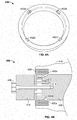
- FIG. 2 is an illustration of an example sterile adapter 200 for use with a robotic surgical system.
- the sterile adapter 200 may be a disposable (e.g. a single-use product). For example, a new sterile adapter 200 may be used for every surgical procedure.
- the sterile adapter 200 is a rigid or semi-rigid device. It may be made from a hard plastic, polymer, or a composite material.
- the sterile adapter 200 secures a drape over a surgical robotic arm to prevent contamination of a sterile field.
- the sterile adapter 200 may include a rigid or semi-rigid collar 202 (e.g., ring or a hollow cylindrical structure) configured to mount (e.g., snap-mount) onto an interface of the surgical robotic arm.
- the sterile adapter 200 may include a rigid or semi-rigid body 204 extending from the collar and shaped to conform to a portion of the surgical robotic arm to tightly secure a flexible drape in place (e.g., with no folds) over the portion of the surgical robotic arm when the drape is attached to the adapter 200.
- the body 204 is one or more tabs 204a-d (e.g., 3, 4, 5, 6, 7, or 8 tabs) that engage an interface on the robot.
- the tabs may "click" into the interface to provide easy and secure mounting of the sterile adapter, and hence sterile drape, on the robot.
- the sterile drape may be glued or welded to the sterile adapter 200 (e.g., during manufacturing).
- the adapter 200 ensures that the drape is tightly stretched over the tool holder and robot interface to provide repeatable and rigid positioning of the tool holder relative to the robotic arm.
- FIG. 3 is an illustration of an sterile drape 304 coupled, via glue or welding, to a sterile adapter 302.
- the sterile drape 304 is glued or welded to the sterile adapter 302. After the welding/gluing dries the part of the drape inside the sterile adapter 302 is stretched. This portion of the drape (i.e., the stretched portion inside of the sterile adapter 302 is the only part of the drape that is located between the tool holder and the robotic arm. As shown in FIG. 3 , the sterile drape 304 is tightly stretched over the opening of the sterile adapter 302. When the sterile adapter 302 is attached to the robotic arm (e.g., clicked into the interface on the robotic arm), the end of the robotic arm will be covered by the sterile drape 304 that is stretched over the opening of the sterile adapter 302. As described below, in some implementations, positioning elements and a tightening screw will protrude through the opening of the sterile adapter and piece the sterile drape when the tool support is applied to the robotic arm.
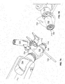
- FIG. 4A-B illustrate an example sterile adapter 400 applied to a robotic surgical system 450.
- Tabs/clips 402 engage grooves 404 on the interface 406 of the robot arm.
- the tabs/clips 402 include a single tab/clip. The tabs/clips may "click" to engage the groove(s) 402 on the robot interface 406.
- the tool holder 410 may be attached to the robot.
- the tool holder 410 may include one or more positioning members 412 (e.g., pins or pegs) that engage one or more holes 414 in the robot interface 406 to provide accurate/repeatable positioning of the tool holder in reference to the robot interface.
- the one or more positioning members 412 may pierce the sterile drape 416 to engage the hole(s) 414.
- the sterile drape 1404 includes a drape opening 1406 that is large enough to allow passage of the positioning pins without puncturing the drape.
- the sterile adapter 1402 stretches the drape to avoid folds as described above.
- the drape opening 1406 is configured to be located inside the sterile adapter 1402 (i.e., the sterile drape does is not on the inside of the sterile adapter).
- a dust cover 1408 may be placed over the drape opening 1406 and attached to the drape 1404.
- the dust cover 1408 may be configured to attach to the drape 1404 using an adhesive material.
- the dust cover 1408 may be removed after the drape 1404 is installed, for example, on the robotic surgical arm, thus reducing contamination of the sterile field. After the sterile drape 1404 is installed, the dust cover 1408 may be removed and the tool holder may be installed.
- the position member(s) 412 may be uniquely shaped to ensure that the tool holder 410 is always appropriately positioned/ oriented on the robot interface 406. In some implementations, the positioning member(s) is/are located on the robot interface 406 and the hole(s) 414 is/are located on the tool holder 410 (i.e., opposite of what is shown in FIG. 4B ).
- the tool holder 410 may be securely attached to the robot using a tightening screw 408.
- the tightening screw 408 may be tightened using a torque wrench or other torque-limited tool.
- the wrench is disposable and/or destroyed after achieving a certain torque.
- the tightening screw is tightened, it pieces the sterile drape 416 and engages threads on the robot interface 406.
- the sterile drape 416 is tightly stretched over the sterile adapter 400, thus when the tightening screw 408 is tightened to the appropriate torque setting, only a single layer of the sterile adapter 400 material is between the tool holder 410 and the robot interface 406.
- the sterile adapter 408 is easy to perforate (e.g., by the position member(s) and the tightening screw) when the sterile tool holder 410 is installed.
- the a bolt or nut is used to securely attached the tool holder 410 to the robot.
- electromagnet(s) is/are used to securely attached the tool holder 410 to the robot.
- the tightening screw 408 and the positioning member(s) 414 protrude through the sterile drape 416.
- these perforations are in the inner space formed by the robot interface 406, the sterile adapter 400, and the tool holder 410. In some implementations, this inner space is hermetically sealed by these three components when the tightening screw 408 is torqued to the appropriate specification.
- FIG. 5 illustrates an example sterilization system 500 with a sterile adapter 502 and sterile drape 508 attached to a robotic arm 510.
- pegs 504 (three pegs as shown in FIG. 5 ) are protruding from the robot interface 506.
- the sterile adapter 502 is attached to the robot interface, the pegs 504 protrude through the sterile drape 508.
- the robotic interface 506 includes holes and the tool support includes pegs that engage the holes when the tool support is attached to the robotic interface.
- FIG. 6 illustrates an example sterilization system 600 with a sterile adapter 614 and sterile drape 602 attached to a robotic arm 604.
- the system 600 includes a sterile drape 602 for covering a surgical robotic arm 604 and preventing contamination of a sterile field.
- the surgical instrument holder 620 may be attached to the interface 616 via a tightening screw 618.
- the tightening screw 618 may protrude through the sterile drape 602 that is tightly stretched over the opening of the sterile adapter 614.
- the robot interface 616 may include one or more positioning elements 622 (e.g., pegs or pins) configured to provide accurate and repeatable positioning of the surgical instrument holder 620 in reference to the robotic arm.
- the surgical instrument holder 620 is holding a drill bit guide 624.
- a user may move the surgical instrument 624 by grasping a handle 606 (e.g., sterile handle).
- An example handle 606 is discussed in U.S. Patent Application No. 14/597883 , the contents of which are hereby incorporated by reference in their entirety.
- the handle 606 adds functionalities and an interface to existing surgical tools such that the robotic system may be commanded from the sterile field during surgery.
- the handle 606 permits a user, such as a surgeon, to physically manipulate the location of the end-effector of a robotic surgical system from a sterile field.
- the handle 606 may include an input device that allows the user to limit the movement of the end-effector, such as limiting the movement to translations or rotations only.
- the handle 606 may detect the presence of a user's hand. This ensures the end effector is only moved when the user manipulates the handle 606 and reduces the likelihood that the end-effector is moved unintentionally.
- robotic surgical system may permit the movement of the end-effector only in circumstances when the presence detector is activated (e.g., a hand of a surgeon is detected as present because the surgeon is holding the sterile handle).
- the handle 606, in certain embodiments, is configured such that it may be used in a sterile environment.
- the design of the handle 606, in certain embodiments, permits rapid mounting of the handle on a surgical tool.
- the handle 606 may be designed to avoid tight spaces between various components of the handle 606, thereby simply the sterilization process.
- the sterile drape 602 includes a flexible covering with a sterile outer surface.
- the sterile drape may be partially conformable to a surgical robotic arm.
- the sterile drape may include an embedded connector 608 configured (e.g., positioned on the flexible covering and sized) to permit electrical contact between the surgical robotic arm 604 (e.g., an actuator of the robotic arm) and a sterile manipulator 606 (e.g., sterile handle) of the robotic arm 604 when the sterile manipulator 606 is separated from the surgical robotic arm 604 by the flexible covering.
- the sterile drape 602 is disposable (e.g., a single-use product).
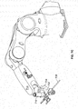
- FIGS. 7A-C illustrate an example sterilization system applied to a robotic surgical system.
- the robotic surgical system is for performing surgery, such as spinal surgery.
- the robotic surgical system may include a robotic arm 714 with an interface 702 for engaging a sterile adapter 706.
- the sterile adapter 706 may be configured to attach to the robotic arm 714 via a robotic interface 706 and tightly stretch the sterile drape 704 to assure repeatable and rigid positioning of the sterile drape 704.
- the sterile drape 704 may be configured to protect the robotic arm from contaminating a sterile field.
- the sterile drape includes a drape connector configured to electrically couple, through the sterile drape, the manipulator (e.g., handle 606) to an electrical system of the robotic surgical system covered by the sterile drape.
- the manipulator 710 e.g., a handle for grasping by a user
- the electrical system of the robotic surgical system may be coupled to a robot connector and the robot connector may be configured to electrically connect to the drape connector.
- the robot connector may electrically couple the drape connector to the robot connector, through the sterile drape 704.
- a surgical instrument holder 714 is configured to securely hold the surgical instrument 708.
- the surgical instrument holder 714 may be attached to the interface 702 via a tightening screw 716.
- the tightening screw 716 may protrude through the sterile drape 704 that is tightly stretched over the opening of the sterile adapter 706.
- the robot interface 702 may include one or more positioning elements 712 (e.g., pegs or pins) configured to provide accurate and repeatable positioning of the surgical instrument holder 714 in reference to the robotic arm.
- the one or more positioning elements 712 may be round or oblong.
- the surgical instrument holder 714 may include one or more studs or holes that engage the one or more positioning elements 712.
- the one or more positioning elements 712 may protrude through the sterile drape 704 when the sterile adapter 706 is attached to the interface 702.
- the one or more positioning elements 712 extend from the robotic arm 714 and engage one or more surgical instrument holder positioning members.
- the one or more positioning elements 712 may be the one or more pegs are configured to extend from the robotic arm and engage one or more holes in the surgical instrument holder 714.
- the robotic surgical system includes a manipulator 710 (e.g., a sterile handle) configured to allow robotically-assisted or unassisted positioning and/or movement of the surgical instrument by a user with at least four degrees of freedom to align an axis defined by the surgical instrument at a desired trajectory in relation to a patient situation.
- a manipulator 710 e.g., a sterile handle
- the surgical instrument is a surgical instrument guide configured to hold and/or restrict movement of a second surgical instrument there through.
- the second surgical instrument may be a drill bit, tap, screw driver, or awl.
- the second surgical instrument may be a drill bit and the surgical instrument guide may be a drill guide.
- the robotic surgical system includes a mobile cart configured to transport the robotic surgical system.
- the sterile drape may be configured to protect the mobile cart from contaminating a sterile field.
- the sterile drape includes a first sterile drape to protect the robotic arm 714 and a second sterile drape to protect the mobile cart.
- the sterile drape may include printed marks configured to assist in proper draping procedure.
- the drape may be folded in a configuration that makes for easily applying the drape to the robotic system.
- the surgical instrument holder is configured to be attached to the robotic arm using a fastening system.
- the fastening system may be a bolt, nut, screw, or one or more electro magnets.
- one or more holding stripes are configured to hold the sterile drape.
- the one or more holding stripes may secure a portion of the sterile drape to the robotic arm.
- the system includes a suppression system configured to remove air from under the sterile drape.
- the suppression system may include a ventilator or a suction device that pumps out the air from under the sterile drape.
- the surgical instrument holder 714 is made from a non-conductive material (e.g., plastic).
- the holder 714 may act as an insulator (prevent electrical conductivity) between the surgical instrument 708 and the robotic arm 714.
- the surgical instrument holder 714 is conductive, however, a non-conducive pad is placed between the holder 714 and the interface 702.
- FIG. 8 is a flow chart illustrating an example method 800 of performing a surgical operation with a robotic surgical system.
- the method 800 includes attaching a sterile adapter to a robotic arm of a robotic surgical system via a robotic interface (802).
- the a sterile drape may be coupled to the sterile adapter (e.g., glued or welded) and is configured to protect the robotic arm from contaminating a sterile field.
- the sterile adapter may be configured to tightly stretch the sterile drape to assure repeatable and rigid positioning of the sterile drape.
- the method 800 includes covering a portion of the robotic surgical system with the sterile drape (804) and connecting a drape connector to a handle connector and a robot connector (806).
- the sterile drape may include the drape connector that is configured to electrically couple the handle connector to the robot connector.
- the method 800 includes securing a portion of the sterile drape to the robotic arm via one or more holding stripes (808).
- the method 800 includes attaching the surgical tool holder to the robotic arm using a fastening system configured to pass through the sterile adapter and the sterile drape (810).
- the surgical tool holder may be configured to slide along one or more positioning elements.
- the one or more positioning elements of a robotic arm of the robotic surgical system may be configured to cause one or more holes in the sterile drape and also provide accurate and repeatable positioning of the surgical instrument holder in reference to the robotic arm.
- the method 800 includes moving a mobile cart transporting the robotic surgical system comprising the robotic arm in proximity to an operating table (812).
- the robotic arm has an end effector that includes a surgical instrument holder holding a surgical instrument attached thereto.
- the method 800 includes stabilizing the mobile cart (814) and maneuvering the robotic arm to a desired position to align an axis defined by the surgical instrument at a desired trajectory in relation to a patient situation (816). In some implementations, the method 800 includes, after maneuvering the robotic arm to the desired position, fixing the position of the robotic arm (and, therefore, the position of the surgical instrument) (818).
- FIG. 10 is an illustration of an example system 1000 for passing electrical signals through a sterile drape.
- system 1000 is achieved using standard (e.g., disposable) cables and connectors. This requires less investment for the developer and user. Moreover, in situations when each cable may only be used for a signal operation, the cost of the disposable components may be significantly reduced.
- the system 100 includes a sterile drape 1002 with a sleeve 1004 which allows for passing a plug 1006 of a cable 1008.
- the plug 1006 is connected to a sterile handle connector 1010 is used to electrically couple the robotic surgical system to the electrical system of the sterile handle via the cable 1008 and plug 1006.
- the sleeve 1004 is sealed using sterile tape 1012.
- the tape 1012 may be wrapped around the sleeve 1004 to seal the sleeve 1004.
- the sleeve 1004 is part of the sterile drape 1002.
- the sleeve 1004 is separate from the drape 1002 and the interface between the sleeve 1004 and the sterile drape 1002 is sealed using sterile adhesive tape 1012 or another sterile adhesive material.
- FIGS. 11A-D are illustrations of the processor applying a sterile drape that allows passage of electrical signals through the drape.
- FIG. 11A illustrates a mode selection panel 1102 on a robotic arm 1106 prior to the installation of a sterile drape.
- a sterile handle connector 1108 is configured to receive a plug 1114 from a cable connected to the electrical system of the robotic surgical system.
- FIG. 11B is an illustration of a sterile drape 1110 and sleeve 1112 placed over the connector 1108. After placing the sterile drape 1110 and sleeve 1112 over connector 1108, the plug 1114 is inserted through the hole in the sleeve and plugged into the connector 1108 as shown in FIG> 11C.
- sterile adhesive tape is wrapped around the sleeve 1112 to seal the sleeve 1112.
- the sleeve 1112 is integrated with (e.g., part of) the sterile drape 1110.
- the sleeve 1112 is separate from the drape 1110 and the interface between the sleeve 1112 and the sterile drape 1110 is sealed using sterile adhesive tape 1116 or another sterile adhesive material.
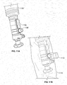
- FIGS. 12A-D are illustrations of an example stiffeners for providing a stiffer sleeve 1206 on a sterile drape 1208.
- the stiffener may be used to simplify passing the plug 1210 though the flexible sleeve 1206.
- the stiffener may be rigid (e.g., made from plastic) or semi-rigid member (e.g. made from rubber, adhesive tape, tape reinforcement).
- the sterile drape stiffener 1202 may be takes integrated into the drape 1208.
- the stiffener the form of a supporting tube 1220 as illustrated in FIG. 12B .
- the supporting tube 1220 may be removable.
- the supporting tube 1220 may have a longitudinal opening which allows the plug 1210 to be plugged into the connector 1204 through the supporting tube 1220.
- the supporting tube 1220 may be inserted before or after applying the drape 1208 to the robot. In some implementations, the supporting tube 1220 may be removably attached to the drape. In some implementations, after inserting the plug 1210 into the connector 1204, the supporting tube 1220 may be removed and sterile adhesive tape is applied to the sleeve 1206 (e.g., as described above).
- the connector adapter 1230 is integrated into the drape 1208 as shown in FIG. 12C .
- the connector adapter 1230 may fit around the connector 1204 and allow for simple access to the connector 1204 by the plug 1210.
- Sterile adhesive tape may be applied to the sleeve 1206 after the plug 1210 is inserted into the connector 1204 (e.g., as described above).
- a drape 1208 with a folded section 1242 is placed around the connector 1240 as shown in FIG. 12D .
- the folded section 1242 of the drape 1208 is unfolded and sterile adhesive tape is applied (e.g., as described above).
- FIG. 13 is an illustration of an example system for passing electrical signals through a sterile drape.
- FIG. 13 illustrates a sterile adapter 1306 (e.g., as described above) and a connector opening 1308.
- a cable and plug are attached to the drape 1302 before draping the robot. For example, a scrub nurse may do this on a sterile table.
- the cable may be passed through the sleeve 1304.
- the drape 1302 and/or sleeve 1304 is/are folded to facilitate passing the cable through the sleeve 1304. After passing the cable through the sleeve 1304, it may be sealed using sterile adhesive tape (e.g., as described above). After sealing the plug and sleeve 1304, the drape 1302 may be applied to the robot and the plug may be connected to the connector by manipulating it from the sterile side of the drape 1302.
Claims (14)
- Drap stérile (1208) destiné à recouvrir un bras robotique chirurgical et empêcher la contamination d'un champ stérile, le drap stérile comprenant un revêtement flexible avec une surface extérieure stérile et un manchon de drap stérile (1206) conçu pour recevoir une fiche électrique (1210) à travers celui-ci, ledit revêtement étant au moins partiellement conformable à un bras robotique chirurgical, dans lequel le manchon de drap stérile est conçu pour être scellé autour d'une partie de la fiche électrique à l'aide d'un ruban adhésif stérile (1012), dans lequel le manchon de drap stérile est conçu pour entourer au moins une partie d'un connecteur (1204) du bras robotique chirurgical et s'étend vers l'extérieur depuis le connecteur (1204), dans lequel le drap stérile comporte un raidisseur de drap sous la forme d'un tube de support (1220) conçu pour permettre au bouchon de passer à travers le manchon de drap stérile.
- Drap stérile (1208) selon l'une quelconque des revendications précédentes, dans lequel le connecteur (1204) est conçu pour permettre un contact électrique entre le bras robotique chirurgical (par exemple, un actionneur du bras robotique) et un manipulateur stérile (par exemple, une poignée stérile) du bras robotique lorsque le manipulateur stérile est séparé du bras robotique chirurgical par le revêtement souple.
- Drap stérile (1208) selon l'une quelconque des revendications précédentes, dans lequel le drap stérile est conçu pour être fixé au champ stérile avant le drapage du bras robotique chirurgical.
- Drap stérile (1208) selon l'une quelconque des revendications précédentes, dans lequel le connecteur (1204) est conçu pour recevoir la fiche électrique (1210) après le passage de la fiche électrique à travers le manchon de drap stérile.
- Drap stérile (1208) selon l'une quelconque des revendications précédentes, dans lequel le connecteur (1204) est conçu pour recevoir la fiche électrique (1210) après (i) le passage de la fiche électrique à travers le manchon de drap stérile et (ii) le manchon de drap stérile est scellé autour d'une partie de la fiche électrique à l'aide d'un ruban adhésif stérile (1012).
- Drap stérile (1208) selon l'une quelconque des revendications précédentes, dans lequel le drap stérile est conçu pour être fixé au drap stérile après le drapage du bras robotique chirurgical.
- Drap stérile (1208) selon la revendication 1, dans lequel le raidisseur de drap (1220) est constitué d'un matériau semi-rigide (par exemple, caoutchouc, ruban adhésif, renfort de ruban).
- Drap stérile (1208) selon la revendication 1, dans lequel le raidisseur de drap (1220) est constitué d'un matériau rigide (par exemple en plastique).
- Drap stérile (1208) selon l'une quelconque des revendications 7 ou 8, dans lequel le raidisseur de drap (1220) est intégré dans le drap stérile.
- Drap stérile (1208) selon l'une quelconque des revendications 7 à 9, dans lequel le raidisseur de drap (1220) est amovible.
- Drap stérile (1208) selon l'une quelconque des revendications 7 à 10, dans lequel le raidisseur de drap (1220) est conçu pour être inséré avant l'application du drap stérile sur le bras robotique chirurgical.
- Drap stérile (1208) selon l'une quelconque des revendications 7 à 10, dans lequel le raidisseur de drap (1220) est conçu pour être inséré après l'application du drap stérile sur le bras robotique chirurgical.
- Drap stérile (1208) selon l'une quelconque des revendications 7 à 12, dans lequel le raidisseur de drap (1220) est conçu pour être retiré après l'application du drap stérile sur le bras robotique chirurgical.
- Drap stérile (1208) selon l'une quelconque des revendications 7 à 13, dans lequel le raidisseur de champ (1220) est conçu pour être retiré après (i) que l'application du drap stérile sur le bras robotique chirurgical et (ii) le manchon de drap stérile est scellé autour d'une partie de la fiche électrique (1210) à l'aide d'un ruban adhésif stérile (1012).
Applications Claiming Priority (3)
| Application Number | Priority Date | Filing Date | Title |
|---|---|---|---|
| US201461930425P | 2014-01-22 | 2014-01-22 | |
| US201461944037P | 2014-02-24 | 2014-02-24 | |
| PCT/EP2015/051273 WO2015110542A1 (fr) | 2014-01-22 | 2015-01-22 | Drap stérile et adaptateur pour recouvrir un bras chirurgical robotique et empêcher la contamination de champ stérile |
Publications (2)
| Publication Number | Publication Date |
|---|---|
| EP3096704A1 EP3096704A1 (fr) | 2016-11-30 |
| EP3096704B1 true EP3096704B1 (fr) | 2021-03-10 |
Family
ID=52391982
Family Applications (1)
| Application Number | Title | Priority Date | Filing Date |
|---|---|---|---|
| EP15700759.2A Active EP3096704B1 (fr) | 2014-01-22 | 2015-01-22 | Drap stérile et adaptateur pour recouvrir un bras chirurgical robotique et empêcher la contamination de champ stérile |
Country Status (3)
| Country | Link |
|---|---|
| US (1) | US20150202009A1 (fr) |
| EP (1) | EP3096704B1 (fr) |
| WO (1) | WO2015110542A1 (fr) |
Families Citing this family (72)
| Publication number | Priority date | Publication date | Assignee | Title |
|---|---|---|---|---|
| WO2012131660A1 (fr) | 2011-04-01 | 2012-10-04 | Ecole Polytechnique Federale De Lausanne (Epfl) | Système robotisé et procédé pour chirurgie rachidienne et autre |
| EP3007636B1 (fr) | 2013-06-11 | 2017-09-27 | Minmaxmedical | Système pour le traitement d'un volume planifié d'une partie de corps |
| WO2014204836A1 (fr) * | 2013-06-18 | 2014-12-24 | Rj Hanlon Company, Inc. | Anneau de protection pour des points de pivotement d'axe d'équipement automatisé |
| US9283048B2 (en) | 2013-10-04 | 2016-03-15 | KB Medical SA | Apparatus and systems for precise guidance of surgical tools |
| US20150196363A1 (en) * | 2013-12-07 | 2015-07-16 | Insurgical Inc. | Limited-use tool disposable enclosure |
| WO2015107099A1 (fr) | 2014-01-15 | 2015-07-23 | KB Medical SA | Appareil entaillé pour guider un instrument pouvant être introduit le long d'un axe pendant une chirurgie rachidienne |
| EP3104803B1 (fr) | 2014-02-11 | 2021-09-15 | KB Medical SA | Poignée stérile de commande d'un système chirurgical robotique à partir d'un champ stérile |
| JP6680686B2 (ja) | 2014-03-17 | 2020-04-15 | インテュイティブ サージカル オペレーションズ, インコーポレイテッド | 手術用ドレープ並びに手術用ドレープ及び取付けセンサを含むシステム |
| CN106659537B (zh) | 2014-04-24 | 2019-06-11 | Kb医疗公司 | 结合机器人手术系统使用的手术器械固持器 |
| US10828120B2 (en) | 2014-06-19 | 2020-11-10 | Kb Medical, Sa | Systems and methods for performing minimally invasive surgery |
| CN105364943B (zh) * | 2014-08-29 | 2020-04-17 | 鸿富锦精密工业(深圳)有限公司 | 固接装置及使用该固接装置的机械臂与机器人 |
| WO2016058076A1 (fr) * | 2014-10-14 | 2016-04-21 | Synaptive Medical (Barbados) Inc. | Outil de référence patient |
| CN107072732B (zh) | 2014-10-23 | 2019-07-05 | 柯惠Lp公司 | 用于机器人手术器械的驱动单元和齿条铺单 |
| US11103316B2 (en) | 2014-12-02 | 2021-08-31 | Globus Medical Inc. | Robot assisted volume removal during surgery |
| US10555782B2 (en) | 2015-02-18 | 2020-02-11 | Globus Medical, Inc. | Systems and methods for performing minimally invasive spinal surgery with a robotic surgical system using a percutaneous technique |
| KR102602379B1 (ko) | 2015-02-20 | 2023-11-16 | 스트리커 코포레이션 | 멸균 차단 조립체, 장착 시스템, 및 수술용 구성 요소들을 결합하기 위한 방법 |
| CN113081009A (zh) | 2015-04-15 | 2021-07-09 | 莫比乌斯成像公司 | 集成式医学成像与外科手术机器人系统 |
| EP3325234B1 (fr) * | 2015-07-23 | 2020-09-09 | Think Surgical, Inc. | Champ de protection pour systèmes robotiques |
| EP3344179B1 (fr) | 2015-08-31 | 2021-06-30 | KB Medical SA | Systèmes de chirurgie robotique |
| CN113274140B (zh) | 2015-09-09 | 2022-09-02 | 奥瑞斯健康公司 | 手术覆盖件 |
| CN108697476B (zh) | 2016-02-26 | 2021-07-23 | 柯惠Lp公司 | 用于机器人手术系统的盖布管理组合件 |
| DE102016109601A1 (de) * | 2016-05-25 | 2017-11-30 | avateramedical GmBH | Anordnung zur sterilen Handhabung von nicht sterilen Einheiten in einer sterilen Umgebung |
| CN114469211A (zh) | 2016-07-12 | 2022-05-13 | 莫比乌斯成像公司 | 多级扩张器与套管系统及方法 |
| KR102577956B1 (ko) * | 2016-07-14 | 2023-09-14 | 인튜어티브 서지컬 오퍼레이션즈 인코포레이티드 | 수술용 드레이프 설치 보조기구 |
| US11883123B2 (en) | 2016-07-14 | 2024-01-30 | Intuitive Surgical Operations, Inc. | Mechanism for managing and retaining a surgical drape |
| GB2552553B (en) | 2016-07-29 | 2022-03-16 | Cmr Surgical Ltd | Motion feedthrough |
| GB2554070B (en) * | 2016-09-14 | 2021-11-10 | Cmr Surgical Ltd | Packaging insert |
| GB2552540B (en) * | 2016-07-29 | 2021-11-24 | Cmr Surgical Ltd | Interface structure |
| US11925431B2 (en) | 2016-07-29 | 2024-03-12 | Cmr Surgical Limited | Motion feedthrough |
| CN109862845B (zh) | 2016-09-16 | 2022-12-30 | 莫比乌斯成像公司 | 用于在手术机器人系统中安装机器人臂的系统和方法 |
| WO2018075784A1 (fr) | 2016-10-21 | 2018-04-26 | Syverson Benjamin | Procédés et systèmes pour régler des trajectoires et des emplacements cibles pour une chirurgie guidée par image |
| US11751948B2 (en) | 2016-10-25 | 2023-09-12 | Mobius Imaging, Llc | Methods and systems for robot-assisted surgery |
| JP6838952B2 (ja) * | 2016-12-07 | 2021-03-03 | 川崎重工業株式会社 | ロボット及びロボットに使用される袋体 |
| KR102282079B1 (ko) * | 2016-12-20 | 2021-07-28 | 버브 서지컬 인크. | 로봇 수술 시스템에 사용하기 위한 멸균 어댑터 제어 시스템 및 통신 인터페이스 |
| US10682129B2 (en) | 2017-03-23 | 2020-06-16 | Mobius Imaging, Llc | Robotic end effector with adjustable inner diameter |
| US11051899B2 (en) * | 2017-04-05 | 2021-07-06 | Warsaw Orthopedic, Inc. | Surgical draping system and method |
| EP3496647B1 (fr) * | 2017-04-19 | 2020-07-01 | Brainlab AG | Système frontal robotique préservant la stérilité |
| US11065069B2 (en) | 2017-05-10 | 2021-07-20 | Mako Surgical Corp. | Robotic spine surgery system and methods |
| US11033341B2 (en) | 2017-05-10 | 2021-06-15 | Mako Surgical Corp. | Robotic spine surgery system and methods |
| WO2018217442A1 (fr) | 2017-05-24 | 2018-11-29 | Covidien Lp | Manchon chirurgical pour systèmes robotisés |
| US11510747B2 (en) | 2017-05-25 | 2022-11-29 | Covidien Lp | Robotic surgical systems and drapes for covering components of robotic surgical systems |
| AU2018316251A1 (en) | 2017-08-11 | 2020-03-05 | Mobius Imaging, Llc | Method and apparatus for attaching a reference marker to a patient |
| EP3681429A4 (fr) * | 2017-08-16 | 2021-09-08 | Covidien LP | Systèmes chirurgicaux robotiques et champs pour recouvrir des éléments de systèmes chirurgicaux robotiques |
| CN111093550B (zh) * | 2017-09-08 | 2023-12-12 | 柯惠Lp公司 | 用于机器人手术组件的能量断开 |
| GB2566330B (en) * | 2017-09-12 | 2020-01-22 | Prometheus Surgical Ltd | Surgical guide production apparatus for use in a sterile environment |
| US11096754B2 (en) | 2017-10-04 | 2021-08-24 | Mako Surgical Corp. | Sterile drape assembly for surgical robot |
| WO2019070997A1 (fr) | 2017-10-04 | 2019-04-11 | GYS Tech, LLC d/b/a Cardan Robotics | Systèmes et procédés pour réaliser une chirurgie rachidienne à accès latéral |
| US11678939B2 (en) * | 2017-10-05 | 2023-06-20 | Mobius Imaging Llc | Methods and systems for performing computer assisted surgery |
| JP6936713B2 (ja) * | 2017-11-27 | 2021-09-22 | 株式会社デンソーウェーブ | ロボット用の保護ジャケット |
| GB2570514B8 (en) * | 2018-01-30 | 2023-06-07 | Cmr Surgical Ltd | Surgical drape |
| US10333296B1 (en) * | 2018-04-20 | 2019-06-25 | Verb Surgical Inc. | Surgical robotic arm with wireless power supply interface |
| CA3099652A1 (fr) * | 2018-05-09 | 2019-11-14 | Moleculight Inc. | Champs d'imagerie, emballage pour champs, procedes d'utilisation de champs d'imagerie, et procedes de deploiement de champ |
| JP7095447B2 (ja) * | 2018-07-18 | 2022-07-05 | 株式会社デンソーウェーブ | ロボット用の保護ジャケット |
| JP7289964B2 (ja) * | 2018-08-28 | 2023-06-12 | 株式会社メディカロイド | 滅菌ドレープおよび手術器具の取付方法 |
| JP6902003B2 (ja) * | 2018-08-28 | 2021-07-14 | 株式会社メディカロイド | 滅菌ドレープおよび手術器具の取付方法 |
| JP7289965B2 (ja) * | 2018-08-28 | 2023-06-12 | 株式会社メディカロイド | 滅菌ドレープおよび手術器具の取付方法 |
| US10945806B2 (en) * | 2018-09-07 | 2021-03-16 | Warsaw Orthopedic, Inc. | Surgical guide and methods of use |
| EP3890643A2 (fr) | 2018-12-04 | 2021-10-13 | Mako Surgical Corporation | Système de montage avec ensemble barrière stérile destiné à être utilisé dans l'accouplement de composants chirurgicaux |
| JP2022515864A (ja) * | 2018-12-30 | 2022-02-22 | メミック イノベーティブ サージェリー リミテッド | ロボットデバイス用の手術用ドレープ |
| US20220273387A1 (en) * | 2019-08-28 | 2022-09-01 | Covidien Lp | Robotic surgical systems and drapes for covering components of robotic surgical systems |
| CN111329592B (zh) * | 2020-03-17 | 2021-06-22 | 上海奥朋医疗科技有限公司 | 血管介入手术中旋夹手的无菌隔绝方法及系统 |
| CN115697232A (zh) * | 2020-05-28 | 2023-02-03 | 马佐尔机器人有限公司 | 用于盖布体积控制的系统和方法 |
| CN114431959B (zh) * | 2020-10-30 | 2023-12-29 | 上海微创医疗机器人(集团)股份有限公司 | 隔离装置和手术机器人系统 |
| CN112716621B (zh) * | 2021-01-20 | 2024-03-12 | 威海威高骨科手术机器人有限公司 | 一种无菌隔离及定位装置 |
| US20220249188A1 (en) * | 2021-02-08 | 2022-08-11 | Mark McBride | Surgical drape having an extendable sleeve for covering a surgical instrument and methods of making and using same |
| CN113069213B (zh) * | 2021-02-23 | 2023-12-01 | 深圳康诺思腾科技有限公司 | 无菌围帘及具有其的手术机器人组件 |
| US11903669B2 (en) | 2021-07-30 | 2024-02-20 | Corindus, Inc | Sterile drape for robotic drive |
| JP7381159B2 (ja) | 2021-12-08 | 2023-11-15 | リバーフィールド株式会社 | ドレープ |
| CN114587602B (zh) * | 2022-02-25 | 2023-05-26 | 上海奥朋医疗科技有限公司 | 用于腹腔镜手术机器人的力反馈感知装置及其腹腔镜手术机器人 |
| CN114587603B (zh) * | 2022-02-25 | 2023-04-25 | 上海奥朋医疗科技有限公司 | 用于腹腔镜手术机器人的无菌隔离装置及其腹腔镜手术机器人 |
| JP7393841B1 (ja) | 2022-03-24 | 2023-12-07 | リバーフィールド株式会社 | 手術支援装置に対するドレープの取付構造及びドレープ |
| US20230355325A1 (en) * | 2022-05-03 | 2023-11-09 | Mazor Robotics Ltd. | Replaceable arm guide and end effector for surgical systems |
Family Cites Families (17)
| Publication number | Priority date | Publication date | Assignee | Title |
|---|---|---|---|---|
| US4799779A (en) * | 1988-03-22 | 1989-01-24 | Mesmer Jeffrey C | Microscope drape |
| US5188093A (en) * | 1991-02-04 | 1993-02-23 | Citation Medical Corporation | Portable arthroscope with periscope optics |
| FI93607C (fi) * | 1991-05-24 | 1995-05-10 | John Koivukangas | Leikkaustoimenpidelaite |
| US5386817A (en) * | 1991-06-10 | 1995-02-07 | Endomedical Technologies, Inc. | Endoscope sheath and valve system |
| US5274500A (en) * | 1992-07-23 | 1993-12-28 | Kansas City Medical, Inc. | Video camera drape with lens |
| US5792045A (en) * | 1994-10-03 | 1998-08-11 | Adair; Edwin L. | Sterile surgical coupler and drape |
| US5803905A (en) * | 1996-03-28 | 1998-09-08 | Ajor Medical Technologies, L.L.C. | Surgical camera and light assembly allowing adjustable focus and zoom capability and method of use |
| US5873814A (en) * | 1996-07-12 | 1999-02-23 | Adair; Edwin L. | Sterile encapsulated endoscopic video monitor and method |
| US6142937A (en) * | 1996-10-11 | 2000-11-07 | Carl-Zeiss-Stiftung | Medical therapeutic and/or diagnostic appliance with a sterilizable position sensing attachment |
| US7666191B2 (en) * | 1996-12-12 | 2010-02-23 | Intuitive Surgical, Inc. | Robotic surgical system with sterile surgical adaptor |
| JP3559441B2 (ja) * | 1998-03-05 | 2004-09-02 | テルモ株式会社 | チューブユニットシステム |
| US7331967B2 (en) * | 2002-09-09 | 2008-02-19 | Hansen Medical, Inc. | Surgical instrument coupling mechanism |
| US20050094269A1 (en) * | 2003-10-31 | 2005-05-05 | Moses Gary L. | Microscope drape coupling system and method |
| US8720448B2 (en) * | 2008-11-07 | 2014-05-13 | Hansen Medical, Inc. | Sterile interface apparatus |
| EP2445439A4 (fr) * | 2009-06-22 | 2015-09-23 | Contour Fabricators Inc | Champ opératoire et procédé d'obtention d'une surface stérile avec celui-ci |
| JP5820601B2 (ja) * | 2011-03-31 | 2015-11-24 | オリンパス株式会社 | マスタマニピュレータ |
| DE102012207060A1 (de) * | 2012-04-27 | 2013-10-31 | Deutsches Zentrum für Luft- und Raumfahrt e.V. | Roboteranordnung zum Einsatz in medizinischen Bereichen |
-
2015
- 2015-01-22 US US14/602,627 patent/US20150202009A1/en not_active Abandoned
- 2015-01-22 EP EP15700759.2A patent/EP3096704B1/fr active Active
- 2015-01-22 WO PCT/EP2015/051273 patent/WO2015110542A1/fr active Application Filing
Non-Patent Citations (1)
| Title |
|---|
| None * |
Also Published As
| Publication number | Publication date |
|---|---|
| US20150202009A1 (en) | 2015-07-23 |
| WO2015110542A1 (fr) | 2015-07-30 |
| EP3096704A1 (fr) | 2016-11-30 |
Similar Documents
| Publication | Publication Date | Title |
|---|---|---|
| EP3096704B1 (fr) | Drap stérile et adaptateur pour recouvrir un bras chirurgical robotique et empêcher la contamination de champ stérile | |
| US10939968B2 (en) | Sterile handle for controlling a robotic surgical system from a sterile field | |
| US11793583B2 (en) | Surgical instrument holder for use with a robotic surgical system | |
| EP3351202B1 (fr) | Guide d'instrument universel destiné à des systèmes chirurgicaux robotiques | |
| US11534184B2 (en) | Universal instrument guide for robotic surgical systems, surgical instrument systems, and methods of their use | |
| US20210038333A1 (en) | Systems and methods for performing minimally invasive surgery | |
| EP3258872B1 (fr) | Systèmes pour pratiquer des micromanipulations chirurgicales à la colonne vertébrale avec un système chirurgical robotique en utilisant une technique percutanée | |
| US20220087729A1 (en) | Robotic surgical systems and methods for rod bending | |
| US11583351B2 (en) | System and method for articulated arm stabilization | |
| US20160081753A1 (en) | Robot-Mounted User Interface For Interacting With Operation Room Equipment |
Legal Events
| Date | Code | Title | Description |
|---|---|---|---|
| PUAI | Public reference made under article 153(3) epc to a published international application that has entered the european phase |
Free format text: ORIGINAL CODE: 0009012 |
|
| 17P | Request for examination filed |
Effective date: 20160810 |
|
| AK | Designated contracting states |
Kind code of ref document: A1 Designated state(s): AL AT BE BG CH CY CZ DE DK EE ES FI FR GB GR HR HU IE IS IT LI LT LU LV MC MK MT NL NO PL PT RO RS SE SI SK SM TR |
|
| AX | Request for extension of the european patent |
Extension state: BA ME |
|
| RIN1 | Information on inventor provided before grant (corrected) |
Inventor name: KOSTRZEWSKI, SZYMON Inventor name: NUSSBAUMER, BILLY |
|
| DAX | Request for extension of the european patent (deleted) | ||
| REG | Reference to a national code |
Ref country code: HK Ref legal event code: DE Ref document number: 1231711 Country of ref document: HK |
|
| STAA | Information on the status of an ep patent application or granted ep patent |
Free format text: STATUS: EXAMINATION IS IN PROGRESS |
|
| 17Q | First examination report despatched |
Effective date: 20190927 |
|
| GRAP | Despatch of communication of intention to grant a patent |
Free format text: ORIGINAL CODE: EPIDOSNIGR1 |
|
| STAA | Information on the status of an ep patent application or granted ep patent |
Free format text: STATUS: GRANT OF PATENT IS INTENDED |
|
| RIC1 | Information provided on ipc code assigned before grant |
Ipc: A61B 46/10 20160101AFI20201112BHEP Ipc: A61B 34/30 20160101ALN20201112BHEP |
|
| RIC1 | Information provided on ipc code assigned before grant |
Ipc: A61B 34/30 20160101ALN20201127BHEP Ipc: A61B 46/10 20160101AFI20201127BHEP |
|
| INTG | Intention to grant announced |
Effective date: 20201214 |
|
| GRAS | Grant fee paid |
Free format text: ORIGINAL CODE: EPIDOSNIGR3 |
|
| STAA | Information on the status of an ep patent application or granted ep patent |
Free format text: STATUS: GRANT OF PATENT IS INTENDED |
|
| GRAA | (expected) grant |
Free format text: ORIGINAL CODE: 0009210 |
|
| STAA | Information on the status of an ep patent application or granted ep patent |
Free format text: STATUS: THE PATENT HAS BEEN GRANTED |
|
| AK | Designated contracting states |
Kind code of ref document: B1 Designated state(s): AL AT BE BG CH CY CZ DE DK EE ES FI FR GB GR HR HU IE IS IT LI LT LU LV MC MK MT NL NO PL PT RO RS SE SI SK SM TR |
|
| REG | Reference to a national code |
Ref country code: GB Ref legal event code: FG4D |
|
| REG | Reference to a national code |
Ref country code: AT Ref legal event code: REF Ref document number: 1368947 Country of ref document: AT Kind code of ref document: T Effective date: 20210315 Ref country code: CH Ref legal event code: EP |
|
| REG | Reference to a national code |
Ref country code: IE Ref legal event code: FG4D |
|
| REG | Reference to a national code |
Ref country code: DE Ref legal event code: R096 Ref document number: 602015066594 Country of ref document: DE |
|
| REG | Reference to a national code |
Ref country code: LT Ref legal event code: MG9D |
|
| PG25 | Lapsed in a contracting state [announced via postgrant information from national office to epo] |
Ref country code: LT Free format text: LAPSE BECAUSE OF FAILURE TO SUBMIT A TRANSLATION OF THE DESCRIPTION OR TO PAY THE FEE WITHIN THE PRESCRIBED TIME-LIMIT Effective date: 20210310 Ref country code: GR Free format text: LAPSE BECAUSE OF FAILURE TO SUBMIT A TRANSLATION OF THE DESCRIPTION OR TO PAY THE FEE WITHIN THE PRESCRIBED TIME-LIMIT Effective date: 20210611 Ref country code: FI Free format text: LAPSE BECAUSE OF FAILURE TO SUBMIT A TRANSLATION OF THE DESCRIPTION OR TO PAY THE FEE WITHIN THE PRESCRIBED TIME-LIMIT Effective date: 20210310 Ref country code: HR Free format text: LAPSE BECAUSE OF FAILURE TO SUBMIT A TRANSLATION OF THE DESCRIPTION OR TO PAY THE FEE WITHIN THE PRESCRIBED TIME-LIMIT Effective date: 20210310 Ref country code: BG Free format text: LAPSE BECAUSE OF FAILURE TO SUBMIT A TRANSLATION OF THE DESCRIPTION OR TO PAY THE FEE WITHIN THE PRESCRIBED TIME-LIMIT Effective date: 20210610 Ref country code: NO Free format text: LAPSE BECAUSE OF FAILURE TO SUBMIT A TRANSLATION OF THE DESCRIPTION OR TO PAY THE FEE WITHIN THE PRESCRIBED TIME-LIMIT Effective date: 20210610 |
|
| REG | Reference to a national code |
Ref country code: AT Ref legal event code: MK05 Ref document number: 1368947 Country of ref document: AT Kind code of ref document: T Effective date: 20210310 |
|
| REG | Reference to a national code |
Ref country code: NL Ref legal event code: MP Effective date: 20210310 |
|
| PG25 | Lapsed in a contracting state [announced via postgrant information from national office to epo] |
Ref country code: RS Free format text: LAPSE BECAUSE OF FAILURE TO SUBMIT A TRANSLATION OF THE DESCRIPTION OR TO PAY THE FEE WITHIN THE PRESCRIBED TIME-LIMIT Effective date: 20210310 Ref country code: LV Free format text: LAPSE BECAUSE OF FAILURE TO SUBMIT A TRANSLATION OF THE DESCRIPTION OR TO PAY THE FEE WITHIN THE PRESCRIBED TIME-LIMIT Effective date: 20210310 Ref country code: SE Free format text: LAPSE BECAUSE OF FAILURE TO SUBMIT A TRANSLATION OF THE DESCRIPTION OR TO PAY THE FEE WITHIN THE PRESCRIBED TIME-LIMIT Effective date: 20210310 |
|
| PG25 | Lapsed in a contracting state [announced via postgrant information from national office to epo] |
Ref country code: NL Free format text: LAPSE BECAUSE OF FAILURE TO SUBMIT A TRANSLATION OF THE DESCRIPTION OR TO PAY THE FEE WITHIN THE PRESCRIBED TIME-LIMIT Effective date: 20210310 |
|
| PG25 | Lapsed in a contracting state [announced via postgrant information from national office to epo] |
Ref country code: SM Free format text: LAPSE BECAUSE OF FAILURE TO SUBMIT A TRANSLATION OF THE DESCRIPTION OR TO PAY THE FEE WITHIN THE PRESCRIBED TIME-LIMIT Effective date: 20210310 Ref country code: AT Free format text: LAPSE BECAUSE OF FAILURE TO SUBMIT A TRANSLATION OF THE DESCRIPTION OR TO PAY THE FEE WITHIN THE PRESCRIBED TIME-LIMIT Effective date: 20210310 Ref country code: CZ Free format text: LAPSE BECAUSE OF FAILURE TO SUBMIT A TRANSLATION OF THE DESCRIPTION OR TO PAY THE FEE WITHIN THE PRESCRIBED TIME-LIMIT Effective date: 20210310 Ref country code: EE Free format text: LAPSE BECAUSE OF FAILURE TO SUBMIT A TRANSLATION OF THE DESCRIPTION OR TO PAY THE FEE WITHIN THE PRESCRIBED TIME-LIMIT Effective date: 20210310 |
|
| PG25 | Lapsed in a contracting state [announced via postgrant information from national office to epo] |
Ref country code: SK Free format text: LAPSE BECAUSE OF FAILURE TO SUBMIT A TRANSLATION OF THE DESCRIPTION OR TO PAY THE FEE WITHIN THE PRESCRIBED TIME-LIMIT Effective date: 20210310 Ref country code: RO Free format text: LAPSE BECAUSE OF FAILURE TO SUBMIT A TRANSLATION OF THE DESCRIPTION OR TO PAY THE FEE WITHIN THE PRESCRIBED TIME-LIMIT Effective date: 20210310 Ref country code: PL Free format text: LAPSE BECAUSE OF FAILURE TO SUBMIT A TRANSLATION OF THE DESCRIPTION OR TO PAY THE FEE WITHIN THE PRESCRIBED TIME-LIMIT Effective date: 20210310 Ref country code: PT Free format text: LAPSE BECAUSE OF FAILURE TO SUBMIT A TRANSLATION OF THE DESCRIPTION OR TO PAY THE FEE WITHIN THE PRESCRIBED TIME-LIMIT Effective date: 20210712 Ref country code: ES Free format text: LAPSE BECAUSE OF FAILURE TO SUBMIT A TRANSLATION OF THE DESCRIPTION OR TO PAY THE FEE WITHIN THE PRESCRIBED TIME-LIMIT Effective date: 20210310 Ref country code: IS Free format text: LAPSE BECAUSE OF FAILURE TO SUBMIT A TRANSLATION OF THE DESCRIPTION OR TO PAY THE FEE WITHIN THE PRESCRIBED TIME-LIMIT Effective date: 20210710 |
|
| REG | Reference to a national code |
Ref country code: DE Ref legal event code: R097 Ref document number: 602015066594 Country of ref document: DE |
|
| PLBE | No opposition filed within time limit |
Free format text: ORIGINAL CODE: 0009261 |
|
| STAA | Information on the status of an ep patent application or granted ep patent |
Free format text: STATUS: NO OPPOSITION FILED WITHIN TIME LIMIT |
|
| PG25 | Lapsed in a contracting state [announced via postgrant information from national office to epo] |
Ref country code: DK Free format text: LAPSE BECAUSE OF FAILURE TO SUBMIT A TRANSLATION OF THE DESCRIPTION OR TO PAY THE FEE WITHIN THE PRESCRIBED TIME-LIMIT Effective date: 20210310 Ref country code: AL Free format text: LAPSE BECAUSE OF FAILURE TO SUBMIT A TRANSLATION OF THE DESCRIPTION OR TO PAY THE FEE WITHIN THE PRESCRIBED TIME-LIMIT Effective date: 20210310 |
|
| 26N | No opposition filed |
Effective date: 20211213 |
|
| PG25 | Lapsed in a contracting state [announced via postgrant information from national office to epo] |
Ref country code: SI Free format text: LAPSE BECAUSE OF FAILURE TO SUBMIT A TRANSLATION OF THE DESCRIPTION OR TO PAY THE FEE WITHIN THE PRESCRIBED TIME-LIMIT Effective date: 20210310 |
|
| PG25 | Lapsed in a contracting state [announced via postgrant information from national office to epo] |
Ref country code: IT Free format text: LAPSE BECAUSE OF FAILURE TO SUBMIT A TRANSLATION OF THE DESCRIPTION OR TO PAY THE FEE WITHIN THE PRESCRIBED TIME-LIMIT Effective date: 20210310 |
|
| PG25 | Lapsed in a contracting state [announced via postgrant information from national office to epo] |
Ref country code: IS Free format text: LAPSE BECAUSE OF FAILURE TO SUBMIT A TRANSLATION OF THE DESCRIPTION OR TO PAY THE FEE WITHIN THE PRESCRIBED TIME-LIMIT Effective date: 20210710 |
|
| PG25 | Lapsed in a contracting state [announced via postgrant information from national office to epo] |
Ref country code: MC Free format text: LAPSE BECAUSE OF FAILURE TO SUBMIT A TRANSLATION OF THE DESCRIPTION OR TO PAY THE FEE WITHIN THE PRESCRIBED TIME-LIMIT Effective date: 20210310 |
|
| REG | Reference to a national code |
Ref country code: CH Ref legal event code: PL |
|
| REG | Reference to a national code |
Ref country code: BE Ref legal event code: MM Effective date: 20220131 |
|
| PG25 | Lapsed in a contracting state [announced via postgrant information from national office to epo] |
Ref country code: LU Free format text: LAPSE BECAUSE OF NON-PAYMENT OF DUE FEES Effective date: 20220122 |
|
| PG25 | Lapsed in a contracting state [announced via postgrant information from national office to epo] |
Ref country code: FR Free format text: LAPSE BECAUSE OF NON-PAYMENT OF DUE FEES Effective date: 20220131 Ref country code: BE Free format text: LAPSE BECAUSE OF NON-PAYMENT OF DUE FEES Effective date: 20220131 |
|
| PG25 | Lapsed in a contracting state [announced via postgrant information from national office to epo] |
Ref country code: LI Free format text: LAPSE BECAUSE OF NON-PAYMENT OF DUE FEES Effective date: 20220131 Ref country code: CH Free format text: LAPSE BECAUSE OF NON-PAYMENT OF DUE FEES Effective date: 20220131 |
|
| PG25 | Lapsed in a contracting state [announced via postgrant information from national office to epo] |
Ref country code: IE Free format text: LAPSE BECAUSE OF NON-PAYMENT OF DUE FEES Effective date: 20220122 |
|
| PGFP | Annual fee paid to national office [announced via postgrant information from national office to epo] |
Ref country code: GB Payment date: 20230127 Year of fee payment: 9 Ref country code: DE Payment date: 20230127 Year of fee payment: 9 |
|
| PG25 | Lapsed in a contracting state [announced via postgrant information from national office to epo] |
Ref country code: HU Free format text: LAPSE BECAUSE OF FAILURE TO SUBMIT A TRANSLATION OF THE DESCRIPTION OR TO PAY THE FEE WITHIN THE PRESCRIBED TIME-LIMIT; INVALID AB INITIO Effective date: 20150122 |