EP3096587A1 - Elektrische heizvorrichtung - Google Patents
Elektrische heizvorrichtung Download PDFInfo
- Publication number
- EP3096587A1 EP3096587A1 EP15168434.7A EP15168434A EP3096587A1 EP 3096587 A1 EP3096587 A1 EP 3096587A1 EP 15168434 A EP15168434 A EP 15168434A EP 3096587 A1 EP3096587 A1 EP 3096587A1
- Authority
- EP
- European Patent Office
- Prior art keywords
- circuit board
- printed circuit
- plug
- board section
- electric heating
- Prior art date
- Legal status (The legal status is an assumption and is not a legal conclusion. Google has not performed a legal analysis and makes no representation as to the accuracy of the status listed.)
- Granted
Links
Images
Classifications
-
- H—ELECTRICITY
- H05—ELECTRIC TECHNIQUES NOT OTHERWISE PROVIDED FOR
- H05B—ELECTRIC HEATING; ELECTRIC LIGHT SOURCES NOT OTHERWISE PROVIDED FOR; CIRCUIT ARRANGEMENTS FOR ELECTRIC LIGHT SOURCES, IN GENERAL
- H05B3/00—Ohmic-resistance heating
- H05B3/02—Details
- H05B3/06—Heater elements structurally combined with coupling elements or holders
-
- F—MECHANICAL ENGINEERING; LIGHTING; HEATING; WEAPONS; BLASTING
- F24—HEATING; RANGES; VENTILATING
- F24H—FLUID HEATERS, e.g. WATER OR AIR HEATERS, HAVING HEAT-GENERATING MEANS, e.g. HEAT PUMPS, IN GENERAL
- F24H3/00—Air heaters
- F24H3/02—Air heaters with forced circulation
- F24H3/04—Air heaters with forced circulation the air being in direct contact with the heating medium, e.g. electric heating element
- F24H3/0405—Air heaters with forced circulation the air being in direct contact with the heating medium, e.g. electric heating element using electric energy supply, e.g. the heating medium being a resistive element; Heating by direct contact, i.e. with resistive elements, electrodes and fins being bonded together without additional element in-between
- F24H3/0429—For vehicles
- F24H3/0441—Interfaces between the electrodes of a resistive heating element and the power supply means
-
- H—ELECTRICITY
- H05—ELECTRIC TECHNIQUES NOT OTHERWISE PROVIDED FOR
- H05B—ELECTRIC HEATING; ELECTRIC LIGHT SOURCES NOT OTHERWISE PROVIDED FOR; CIRCUIT ARRANGEMENTS FOR ELECTRIC LIGHT SOURCES, IN GENERAL
- H05B2203/00—Aspects relating to Ohmic resistive heating covered by group H05B3/00
- H05B2203/022—Heaters specially adapted for heating gaseous material
- H05B2203/023—Heaters of the type used for electrically heating the air blown in a vehicle compartment by the vehicle heating system
Definitions
- the invention relates to an electric heater according to the preamble of claim 1. Furthermore, the invention relates to a heating or air conditioning system with such a heater.
- the waste heat of the motor vehicle engine is usually used for the heating of the vehicle interior of a motor vehicle. This waste heat arises after the vehicle engine is turned on. In a sufficient amount for the desired heat output, however, the waste heat can usually be provided only after a certain warm-up time. In addition, in modern, low-consumption motor vehicle engines, a comparatively small amount of waste heat is created. In motor vehicles with an electric motor as a drive motor, this heat source completely falls away or is considerably reduced, because the electric motor hardly generates waste heat in comparison to an internal combustion engine. It is therefore customary, especially in cold weather conditions, to use electric heaters or additional electric heaters.
- EP 0 901 311 A2 discloses in this regard an electric heating device for motor vehicles with a plurality of block-like composite heating elements.
- the individual heating elements are held together by a frame.
- a control unit for electronic control of the heating power is integrated, so that the heating elements and the control unit form a common structural unit.
- heat sinks are provided for the cooling of the control unit, which protrude into the air stream to be heated.
- additional components are used to cool the control unit, which increases the cost and complicates the assembly.
- An embodiment of the invention relates to an electrical heating device, in particular for a motor vehicle, comprising at least one heating element and at least one control device having a housing, with at least one printed circuit board, with a first printed circuit board section and a second printed circuit board section, and with at least one first plug-in device and with at least one second plug-in device, wherein the two plug-in devices serve for connecting the at least one heating element to the control device.
- the housing partially accommodates the at least one printed circuit board, wherein the first printed circuit board section is arranged in the housing and the second printed circuit board section projects out of the housing and the at least one first plug-in device is connected to the second printed circuit board section and the at least one second plug-in device is connected to the heating element ,
- a printed circuit board section and / or plug-in devices arranged on a printed circuit board section and / or adjacent to a printed circuit board section protrude from the housing, permits energy-saving cooling of electrical components.
- expensive cabling which otherwise require further material and additional space omitted.
- the at least one first plug-in device and the at least one second plug-in device are designed to be complementary to one another and / or detachably connectable to one another.
- An additional embodiment of the electric heating device provides that the at least one first plug-in device is soldered or crimped to the second printed circuit board section. This allows a simple and uncomplicated connection of important components of the electric heater, resulting in advantages for the installation and maintenance of the electric heater.
- the first printed circuit board section has a part which is essentially watertight.
- the first printed circuit board section has a part which is essentially watertight.
- the at least one heating element has a number of positive-temperature-coefficient elements. These components of the electric heating device, also referred to as PTC elements, ensure that a comfortable temperature for vehicle occupants is quickly established in the vehicle interior and, in particular, the windscreen is free from moisture fogging.
- the at least one heating element is formed substantially block-like and has a number of continuous, mutually parallel openings as air channels.
- the openings advantageously allow the promotion of an air flow through the heating element. The air flow heats up and, as soon as it is directed into the vehicle interior, rapidly generates the room temperature desired there by the vehicle occupants.
- a particularly advantageous embodiment of the electric heating device provides that the at least one heating element has at least one heat-dissipating surface, with a number of heat-conducting fins, which increase the at least one heat-dissipating surface. Due to the surface-enlarging effect of the heat-conducting ribs, the heat transfer from the at least one heating element to the air flow conveyed through the openings arranged on the heating element is still considerably improved.
- the at least one control device in the region of the printed circuit board has at least one connection for a power supply and / or at least one Connection for a control logic on. This allows the heater to connect in a structurally simple manner to the on-board power supply system of a motor vehicle and / or integrate it into the on-board electronics of a motor vehicle.
- the at least one control device has at least one power transistor, in particular a metal-oxide-semiconductor field-effect transistor (MOSFET).
- MOSFET metal-oxide-semiconductor field-effect transistor
- An advantageous embodiment of the heating and / or air conditioning, in particular for a motor vehicle, with an air duct provides that in the air duct designed according to the above description electrical heating device can be arranged.
- the second printed circuit board section and / or the at least one first plug-in device and the at least one second plug-in device are or are arranged in the air duct.
- the second printed circuit board section and / or the at least one first plug-in device and the at least one second plug-in device are or are arranged in an air flow to be heated in the air duct.
- a heating or air conditioning system is created, which also produces a very good heating performance in motor vehicles with modern, consumption-optimized and only slightly waste heat producing engines and in motor vehicles with electric motors.
- sensitive to be cooled components of the electric heater are cooled in energy, material and space-saving manner.
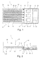
- FIG. 1 shows a schematic view of an embodiment of an electric heater 1.
- the viewing direction of the view is carried out vertically to a arranged in the electric heater 1 circuit board 4th
- the electric heater 1 is arranged in a heating system, not shown, of a motor vehicle.
- the electric heating device 1 is arranged in an air conditioning system of a motor vehicle.
- the electric heater 1 has a housing 2 and at least one printed circuit board 4.
- the at least one printed circuit board 4 may have a rigid structure or else a flexible structure.
- the at least one printed circuit board 4 may be a single-layer printed circuit board 4, a two-layer printed circuit board 4 or a multilayer printed circuit board 4.
- the printed circuit board 4 has a first printed circuit board section 5 and a second printed circuit board section 6 arranged adjacent to the first printed circuit board section 5.
- connection 13 for the electrical power supply of the electric heating device 1 is arranged in the region of the first printed circuit board section 5.
- the electric heater 1 can be connected to an unillustrated on-board power supply system of a motor vehicle.
- connection 14 for an electronic connection of the electric heating device 1 is arranged with a control logic, not shown.
- the electric heating device 1 can be activated, for example, via an on-board computer arranged in the motor vehicle.
- the connection can be made for example via a data bus, such as via a CAN bus or a LIN bus.
- the terminal 13 and / or the terminal 14 are outside the first printed circuit board section 5 arranged.
- the electric heater 1 may have more than one terminal 13 and / or more than one terminal 14.
- the control of the heating power of the electric heater can be done via data bus or via another signal, such as an ON / OFF signal, in particular from 0 to 12V or via a PWM signal.
- the electrical heating device 1 has a control device 3 which has three electronic power transistors 19 in the region of the first printed circuit board section 5.
- the electrical heating device 1 or the control device 3 has one, two, four, five, six or a plurality of such power transistors 19 in order to be able to control the current flow of the PTC elements 10 of the heating device 1.
- the at least one power transistor 19 may be formed, for example, as a metal-oxide-semiconductor field-effect transistor.
- the first circuit board section 5 has a substantially watertight closed part 17.
- the substantially watertight closed part 17 for example, a plastic sheath, not shown, which is advantageously arranged in the housing (2) or by the housing (2) itself may be formed.
- the electric heater 1 has five first connectors 7 and five second connectors 8.
- the electric heater has one, two, three, four, six, seven, eight, nine, ten, or a plurality of first connectors 7 and second connectors 8.
- the plug-in devices 7 are advantageous on the Soldered PCB.
- male plugs 8 may be inserted, which are connected to the heating element or integrally formed therewith.
- the plug-in devices 8 may be designed as female plug-in devices and the plug-in devices 7 correspondingly as male plug devices.
- the at least one first plug-in device 7 and the at least one second plug-in device 8 are formed, for example, complementary to one another and in particular can be detachably or non-detachably connected to one another.
- the heating element 9 can be connected to the control device 3.
- the at least one first plug-in device 7 is in the in the Figures 1 and 2 illustrated embodiment connected to the at least one circuit board 4.
- the at least one first plug-in device 7 is arranged in the region of the second printed circuit board section 6 and connected thereto.
- the at least one second plug-in device 8 is in the in the Figures 1 and 2 illustrated embodiment with at least one heating element 9 connected.
- the at least one heating element 9 has in the in FIG. 1 illustrated embodiment on a rectangular and substantially block-like structure.
- the block-type structure has a series of substantially strip-shaped PTC elements 10, which are arranged, for example, between contact plates 20 and heat-conducting ribs 12.
- the heat conducting ribs 12 enlarge a surface of the heating element 9, not shown, and thereby improve the heat transfer to the air flowing through.
- the arranged between the PTC elements 10 and the heat conducting ribs 12 contact plates 20 are electrically conductively and thermally conductively connected to the PTC elements 10 and optionally with the heat conducting ribs 12.
- the at least one block-shaped heating element 9 can also be arranged in a particular rectangular frame beyond.
- the at least one heating element 9 has, for example, openings 11 arranged parallel to one another as integrated air ducts.
- the openings 11 are arranged in this embodiment substantially in an air flow direction 16 in an air duct 15.
- the air duct 15 is arranged for example within the heating or air conditioning, not shown.
- FIG. 2 shows a schematic side view of an electric heater 1 according to FIG. 1 ,
- an air flow in particular in the air flow direction 16 is conveyed by way of example.
- the air flow flows through the openings 11 arranged in parallel, while it is heated in particular by the heat-conducting ribs 12 and the PTC elements 10.
- the heat-conducting fins 12 and the PTC elements 10 are cooled by the air flow 21.
- the in the Figures 1 and 2 illustrated air duct 15 has an air duct wall 18. Through the one air duct wall 18, the second printed circuit board section 6 projects into the area of the air duct 15. In the process, the second printed circuit board section 6 heats the air flow 21 or the air flow 21 cools the second printed circuit board section 6.
- the at least one first plug-in device 7 is arranged in the region of the second printed circuit board section 6.
- the at least one first plug-in device 7 is connected to the at least one second plug-in device 8.
- the at least one first Plug-in device 7 and the at least one second plug-in device 8 arranged in the region of the air flow 21.
- the at least one first plug-in device 7 and the at least one second plug-in device 8 heat the air flow. At the same time, the at least one first plug-in device 7 and the at least one second plug-in device 8 are cooled by the air flow. As a result, the second printed circuit board section 6 is also cooled and / or serves to conduct heat from the power transistors 19 of the control device 3 to the first plug-in device 7, thereby also cooling the control device 3 or cooling its power transistors 19.
- the first circuit board portion 5 is arranged in particular in the housing 2.
- the second circuit board section 6 projects out of the housing 2.
- a part of the printed circuit board 4 projects out of the housing, which is larger or smaller than the second printed circuit board section 6.
- a the air duct 15 facing part of the housing 2 in the region of the air duct wall 18 is arranged.
- a part of the housing 2 projects into the region of the air channel 15.
Landscapes
- Engineering & Computer Science (AREA)
- Physics & Mathematics (AREA)
- Thermal Sciences (AREA)
- Chemical & Material Sciences (AREA)
- Combustion & Propulsion (AREA)
- Mechanical Engineering (AREA)
- General Engineering & Computer Science (AREA)
- Air-Conditioning For Vehicles (AREA)
Abstract
Description
- Die Erfindung betrifft eine elektrische Heizvorrichtung gemäß dem Oberbegriff von Anspruch 1. Darüber hinaus betrifft die Erfindung eine Heiz- oder Klimaanlage mit einer solchen Heizvorrichtung.
- Für die Beheizung des Fahrzeuginnenraums eines Kraftfahrzeugs wird üblicherweise die Abwärme des Kraftfahrzeugmotors verwendet. Diese Abwärme entsteht, nachdem der Kraftfahrzeugmotor eingeschaltet ist. In einem für die gewünschte Heizleistung ausreichenden Maß kann die Abwärme in der Regel jedoch erst nach einer gewissen Warmlaufzeit bereitgestellt werden. Hinzu kommt, dass bei neueren, verbrauchsärmeren Kraftfahrzeugmotoren ein vergleichsweise geringes Maß an Abwärme entsteht. Bei Kraftfahrzeugen mit einem Elektromotor als Antriebsmotor fällt diese Wärmequelle vollständig weg bzw. ist erheblich reduziert, weil der Elektromotor im Vergleich zu einem Verbrennungsmotor kaum Abwärme erzeugt. Daher ist es üblich, vor allem bei kalten Witterungsbedingungen, elektrische Heizvorrichtungen bzw. elektrische Zusatzheizvorrichtungen einzusetzen.
-
EP 0 901 311 A2 offenbart diesbezüglich eine elektrische Heizvorrichtung für Kraftfahrzeuge mit mehreren blockartig zusammengesetzten Heizelementen. Dabei werden die einzelnen Heizelemente durch einen Rahmen zusammengehalten. In den Rahmen ist auch eine Steuereinheit zur elektronischen Regelung der Heizleistung integriert, so dass die Heizelemente und die Steuereinheit eine gemeinsame Baueinheit bilden. Dabei sind für die Kühlung der Steuereinheit Kühlkörper vorgesehen, die in den zu erwärmenden Luftstrom ragen. Dadurch werden zusätzliche Bauelemente eingesetzt, um die Steuereinheit kühlen zu können, was die Kosten erhöht und die Montage verkompliziert. - Ausgehend von diesem Stand der Technik ist es die Aufgabe der Erfindung, eine weiter verbesserte elektrische Heizvorrichtung bereitzustellen, die insbesondere energie-, material- und bauraumsparend ausgebildet ist und dennoch eine ausreichende Kühlung elektronischer Komponenten der elektrischen Heizvorrichtung ermöglicht.
- Darüber hinaus ist es die Aufgabe der Erfindung, eine Heizungs- und/oder Klimaanlage zu schaffen, in welcher eine solche elektrische Heizvorrichtung einsetzbar ist.
- Die Aufgabe zur elektrischen Heizvorrichtung wird mit den Merkmalen von Anspruch 1 gelöst.
- Ein Ausführungsbeispiel der Erfindung betrifft eine elektrische Heizvorrichtung, insbesondere für ein Kraftfahrzeug, mit zumindest einem Heizelement und mit zumindest einer Steuervorrichtung mit einem Gehäuse, mit zumindest einer Leiterplatte, mit einem ersten Leiterplattenabschnitt und einem zweiten Leiterplattenabschnitt, und mit zumindest einer ersten Steckvorrichtung und mit zumindest einer zweiten Steckvorrichtung, wobei die beiden Steckvorrichtungen zum Verbinden des zumindest einen Heizelements mit der Steuervorrichtung dienen. Das Gehäuse nimmt die zumindest eine Leiterplatte teilweise auf, wobei der erste Leiterplattenabschnitt in dem Gehäuse angeordnet ist und der zweite Leiterplattenabschnitt aus dem Gehäuse herausragt und die zumindest eine erste Steckvorrichtung mit dem zweiten Leiterplattenabschnitt verbunden ist und die zumindest eine zweite Steckvorrichtung mit dem Heizelement verbunden ist. Eine solche Bauform, bei der ein Leiterplattenabschnitt und/oder auf einem Leiterplattenabschnitt und/oder benachbart zu einem Leiterplattenabschnitt angeordnete Steckvorrichtungen aus dem Gehäuse herausragen, erlaubt eine energiesparende Kühlung elektrischer Komponenten. Außerdem entfallen aufwendige Verkabelungen, die andernfalls weiteres Material sowie zusätzlichen Bauraum beanspruchen.
- In einem weiteren Ausführungsbeispiel der elektrischen Heizvorrichtung sind die zumindest eine erste Steckvorrichtung und die zumindest eine zweite Steckvorrichtung komplementär zueinander ausgebildet und/oder lösbar miteinander verbindbar.
- Eine zusätzliche Ausführungsform der elektrischen Heizvorrichtung sieht vor, dass die zumindest eine erste Steckvorrichtung mit dem zweiten Leiterplattenabschnitt verlötet oder vercrimpt ist. Dies ermöglicht eine einfache und unkomplizierte Verbindung wichtiger Komponenten der elektrischen Heizvorrichtung, woraus sich Vorteile für die Montage und die Wartung der elektrischen Heizvorrichtung ergeben.
- In einem weiteren Ausführungsbeispiel der elektrischen Heizvorrichtung weist der erste Leiterplattenabschnitt einen Teil auf, welcher im Wesentlichen wasserdicht abgeschlossen ist. Dadurch sind besonders wasserempfindliche Komponenten der elektrischen Heizvorrichtung vor Wasser geschützt. In vorteilhafter Weise wird damit die Lebensdauer der elektrischen Heizvorrichtung verlängert und ihre Störungsanfälligkeit deutlich reduziert.
- In einem zusätzlichen Ausführungsbeispiel der elektrischen Heizvorrichtung weist das zumindest eine Heizelement eine Anzahl von Positive-Temperature-Coefficient-Elementen auf. Diese auch als PTC-Elemente bezeichneten Komponenten der elektrischen Heizvorrichtung gewährleisten, dass sich im Fahrzeuginnenraum rasch eine für Fahrzeuginsassen komfortable Temperatur einstellt und insbesondere die Windschutzscheibe frei von Feuchtigkeitsbeschlag ist.
- Bei einer weiteren Ausführungsform der elektrischen Heizvorrichtung ist das zumindest eine Heizelement im Wesentlichen blockartig ausgebildet und weist eine Anzahl von durchgehenden, parallel zueinander angeordneten Öffnungen als Luftkanäle auf. Die Öffnungen erlauben in vorteilhafter Weise die Förderung eines Luftstroms durch das Heizelement. Dabei erwärmt sich der Luftstrom und erzeugt, sobald er in den Fahrzeuginnenraum geleitet wird, rasch die dort von den Fahrzeuginsassen gewünschte Raumtemperatur.
- Ein besonders vorteilhaftes Ausführungsbeispiel der elektrischen Heizvorrichtung sieht vor, dass das zumindest eine Heizelement zumindest eine wärmeableitende Oberfläche aufweist, mit einer Anzahl von Wärmeleitrippen, welche die zumindest eine wärmeableitende Oberfläche vergrößern. Durch die oberflächenvergrößernde Wirkung der Wärmeleitrippen wird die Wärmeübertragung von dem zumindest einen Heizelement auf den durch die am Heizelement angeordneten Öffnungen geförderten Luftstrom noch erheblich verbessert.
- In einem weiteren Ausführungsbeispiel der elektrischen Heizvorrichtung weist die zumindest eine Steuervorrichtung im Bereich der Leiterplatte zumindest einen Anschluss für eine Stromversorgung und/oder zumindest einen Anschluss für eine Ansteuerlogik auf. Hierdurch lässt sich die Heizvorrichtung auf konstruktiv einfache Weise an das Bordstromnetz eines Kraftfahrzeugs anschließen und/oder in die Bordelektronik eines Kraftfahrzeugs integrieren.
- Eine vorteilhafte Ausführungsform der elektrischen Heizvorrichtung sieht vor, dass die zumindest eine Steuervorrichtung zumindest einen Leistungstransistor, wie insbesondere einen Metall-Oxid-Halbleiter-Feldeffekttransistor (MOSFET) aufweist. Durch die Verwendung dieses auch als MOSFET bezeichneten Typs von Transistoren wird die Steuerung der elektrischen Heizvorrichtung sowie ihre Integration in die Bordelektronik erheblich erleichtert.
- Die Aufgabe zur Heizungs- und/oder Klimaanlage wird mit den Merkmalen der Ansprüche 10, 11 und 12 gelöst.
- Eine vorteilhafte Ausführungsform der Heizungs- und/oder Klimaanlage, insbesondere für ein Kraftfahrzeug, mit einem Luftkanal, sieht vor, dass in dem Luftkanal eine gemäß der oben genannten Beschreibung gestaltete elektrische Heizvorrichtung anordenbar ist.
- Bei einer besonders vorteilhaften Ausführungsform der Heizungs- und/oder Klimaanlage ist bzw. sind der zweite Leiterplattenabschnitt und/oder die zumindest eine erste Steckvorrichtung und die zumindest eine zweite Steckvorrichtung im Luftkanal angeordnet.
- In einem weiteren Ausführungsbeispiel der Heizungs- und/oder Klimaanlage ist bzw. sind der zweite Leiterplattenabschnitt und/oder die zumindest eine erste Steckvorrichtung und die zumindest eine zweite Steckvorrichtung in einem zu erwärmenden Luftstrom in dem Luftkanal angeordnet.
- Dadurch wird eine Heizungs- oder Klimaanlage geschaffen, die auch in Kraftfahrzeugen mit modernen, verbrauchsoptimierten und nur wenig Abwärme produzierenden Motoren sowie in Kraftfahrzeugen mit Elektromotoren eine sehr gute Heizleistung erzeugt. Darüber hinaus werden empfindliche zu kühlende Komponenten der elektrischen Heizvorrichtung auf energie-, material- und bauraumsparende Weise gekühlt.
- Weitere vorteilhafte Ausgestaltungen sind durch die nachfolgende Figurenbeschreibung und durch die Unteransprüche beschrieben.
- Nachstehend wird die Erfindung auf der Grundlage zumindest eines Ausführungsbeispiels anhand der Figuren der Zeichnung näher erläutert. Es zeigen:
- Fig. 1
- eine schematische Ansicht einer elektrischen Heizvorrichtung, und
- Fig. 2
- eine schematische seitliche Ansicht der elektrischen Heizvorrichtung nach
Figur 1 . - Die
Figur 1 zeigt eine schematische Ansicht eines Ausführungsbeispiels einer elektrischen Heizvorrichtung 1. Die Blickrichtung der Ansicht erfolgt dabei vertikal zu einer in der elektrischen Heizvorrichtung 1 angeordneten Leiterplatte 4. - Die elektrische Heizvorrichtung 1 ist in einer nicht dargestellten Heizungsanlage eines Kraftfahrzeugs angeordnet. In einem alternativen Ausführungsbeispiel ist die elektrische Heizungsvorrichtung 1 in einer Klimaanlage eines Kraftfahrzeugs angeordnet.
- Die elektrische Heizvorrichtung 1 weist ein Gehäuse 2 und zumindest eine Leiterplatte 4 auf. Die zumindest eine Leiterplatte 4 kann eine starre Struktur oder auch eine flexible Struktur aufweisen. Darüber hinaus kann es sich in verschiedenen Ausführungsformen der elektrischen Heizvorrichtung 1 bei der zumindest einen Leiterplatte 4 um eine einlagige Leiterplatte 4, eine zweilagige Leiterplatte 4 oder eine mehrlagige Leiterplatte 4 handeln.
- Die Leiterplatte 4 weist einen ersten Leiterplattenabschnitt 5 und einen benachbart zum ersten Leiterplattenabschnitt 5 angeordneten zweiten Leiterplattenabschnitt 6 auf.
- In dem in
Figur 1 dargestellten Ausführungsbeispiel ist im Bereich des ersten Leiterplattenabschnitts 5 ein Anschluss 13 zur elektrischen Stromversorgung der elektrischen Heizvorrichtung 1 angeordnet. Mittels des Anschlusses 13 kann die elektrische Heizvorrichtung 1 an ein nicht dargestelltes Bordstromnetz eines Kraftfahrzeugs angeschlossen werden. - Darüber hinaus ist in diesem Ausführungsbeispiel im Bereich des ersten Leiterplattenabschnitts 5 ein Anschluss 14 für eine elektronische Verbindung der elektrischen Heizvorrichtung 1 mit einer nicht dargestellten Ansteuerlogik angeordnet. Mittels des Anschlusses 14 ist die elektrische Heizvorrichtung 1 beispielsweise über einen im Kraftfahrzeug angeordneten Bordcomputer ansteuerbar. Die Verbindung kann beispielsweise über einen Datenbus erfolgen, wie über einen CAN-Bus oder einen LIN-Bus. In alternativen Ausführungsbeispielen der elektrischen Heizvorrichtung 1 sind der Anschluss 13 und/oder der Anschluss 14 außerhalb des ersten Leiterplattenabschnitts 5 angeordnet. Darüber hinaus kann die elektrische Heizvorrichtung 1 in weiteren Ausführungsbeispielen mehr als einen Anschluss 13 und/oder mehr als einen Anschluss 14 aufweisen. Die Ansteuerung der ,Heizleistung der elektrischen Heizvorrichtung kann dabei über Datenbus oder über ein anderweitiges Signal, wie über ein ON/OFF-Signal insbesondere von 0-12V oder über ein PWM-Signal, erfolgen.
- In dem in
Figur 1 dargestellten Ausführungsbeispiel weist die elektrische Heizvorrichtung 1 eine Steuervorrichtung 3 auf, die im Bereich des ersten Leiterplattenabschnitts 5 drei elektronische Leistungstransistoren 19 aufweist. In alternativen Ausführungsbeispielen weist die elektrische Heizvorrichtung 1 bzw. die Steuervorrichtung 3 eine, zwei, vier, fünf, sechs oder eine Mehrzahl solcher Leistungstransistoren 19 auf, um den Stromfluss der PTC-Elemente 10 der Heizvorrichtung 1 steuern zu können. - Der zumindest eine Leistungstransistor 19 kann beispielsweise als MetallOxid-Halbleiter-Feldeffekttransistor ausgebildet sein.
- In dem in
Figur 1 dargestellten Ausführungsbeispiel weist der erste Leiterplattenabschnitt 5 einen im Wesentlichen wasserdicht abgeschlossen Teil 17 auf. Hierzu weist der im Wesentlichen wasserdicht abgeschlossene Teil 17 beispielsweise eine nicht dargestellte Kunststoffummantelung auf, die vorteilhaft in dem Gehäuse (2) angeordnet ist oder auch durch das Gehäuse (2) selbst ausgebildet sein kann. - Das in den
Figuren 1 und 2 dargestellte Ausführungsbeispiel der elektrischen Heizvorrichtung 1 weist fünf erste Steckvorrichtungen 7 und fünf zweite Steckvorrichtungen 8 auf. In alternativen Ausführungsbeispielen weist die elektrische Heizvorrichtung eine, zwei, drei, vier, sechs, sieben, acht, neun, zehn oder eine Mehrzahl von ersten Steckvorrichtungen 7 und zweiten Steckvorrichtungen 8 auf. die Steckvorrichtungen 7 sind vorteilhaft auf der Leiterplatte verlötet. In die weiblichen Steckvorrichtungen 7 können männliche Steckvorrichtungen 8 eingesteckt sein, die an dem Heizelement verbunden oder einteilig mit diesem ausgebildet sind. Alternativ können auch die Steckvorrichtungen 8 als weibliche Steckvorrichtungen ausgebildet sein und die Steckvorrichtungen 7 entsprechend als männliche Steckvorrichtungen. - Die zumindest eine erste Steckvorrichtung 7 und die zumindest eine zweite Steckvorrichtung 8 sind beispielsweise komplementär zueinander ausgebildet und können insbesondere lösbar oder nicht lösbar miteinander verbunden werden. Dadurch kann das Heizelement 9 mit der Steuervorrichtung 3 verbunden werden.
- Die zumindest eine erste Steckvorrichtung 7 ist in dem in den
Figuren 1 und 2 dargestellten Ausführungsbeispiel mit der zumindest einen Leiterplatte 4 verbunden. Dabei ist die zumindest eine erste Steckvorrichtung 7 im Bereich des zweiten Leiterplattenabschnitts 6 angeordnet und mit diesem verbunden. - Die zumindest eine zweite Steckvorrichtung 8 ist in dem in den
Figuren 1 und 2 dargestellten Ausführungsbeispiel mit zumindest einem Heizelement 9 verbunden. - Das zumindest eine Heizelement 9 weist in dem in
Figur 1 dargestellten Ausführungsbeispiel einen rechteckförmigen sowie im Wesentlichen blockartigen Aufbau auf. Der blockartige Aufbau weist beispielhaft eine Reihe von im Wesentlichen streifenförmigen PTC-Elementen 10 auf, die beispielhaft zwischen Kontaktblechen 20 und Wärmeleitrippen 12 angeordnet sind. Die Wärmeleitrippen 12 vergrößern eine nicht dargestellte Oberfläche des Heizelements 9 und verbessern dadurch den Wärmeübergang zur durchströmenden Luft. - Die zwischen den PTC-Elementen 10 und den Wärmeleitrippen 12 angeordneten Kontaktbleche 20 sind mit den PTC-Elementen 10 und gegebenenfalls mit den Wärmeleitrippen 12 elektrisch leitend und thermisch leitend verbunden. Das zumindest eine blockartig aufgebaute Heizelement 9 kann darüber hinaus auch in einem insbesondere rechteckförmigen Rahmen angeordnet sein.
- Zwischen den Wärmeleitrippen 12 und den PTC-Elementen 10 weist das zumindest eine Heizelement 9 beispielhaft parallel zueinander angeordnete Öffnungen 11 als integrierte Luftkanäle auf. Die Öffnungen 11 sind in diesem Ausführungsbeispiel im Wesentlichen in einer Luftströmungsrichtung 16 in einem Luftkanal 15 angeordnet. Der Luftkanal 15 ist beispielsweise innerhalb der nicht dargestellten Heizungs- oder Klimaanlage angeordnet.
-
Figur 2 zeigt eine schematische seitliche Ansicht einer elektrischen Heizvorrichtung 1 gemäßFigur 1 . In dem Luftkanal 15 wird beispielhaft ein Luftstrom, insbesondere in Luftströmungsrichtung 16, gefördert. Dabei strömt der Luftstrom durch die parallel angeordneten Öffnungen 11, während er insbesondere von den Wärmeleitrippen 12 und den PTC-Elementen 10 erwärmt wird. Gleichzeitig werden die Wärmeleitrippen 12 und die PTC-Elemente 10 durch den Luftstrom 21 gekühlt. - Der in den
Figuren 1 und 2 beispielhaft dargestellte Luftkanal 15 weist eine Luftkanalwand 18 auf. Durch die eine Luftkanalwand 18 ragt der zweite Leiterplattenabschnitt 6 in den Bereich des Luftkanals 15 hinein. Dabei erwärmt der zweite Leiterplattenabschnitt 6 den Luftstrom 21 bzw. kühlt der Luftstrom 21 den zweiten Leiterplattenabschnitt 6. Im Bereich des zweiten Leiterplattenabschnitts 6 ist die zumindest eine erste Steckvorrichtung 7 angeordnet. Die zumindest eine erste Steckvorrichtung 7 ist mit der zumindest einen zweiten Steckvorrichtung 8 verbunden. In dem in denFiguren 1 und 2 dargestellten Ausführungsbeispiel sind die zumindest eine erste Steckvorrichtung 7 und die zumindest eine zweite Steckvorrichtung 8 im Bereich des Luftstroms 21 angeordnet. Dabei erwärmen die zumindest eine erste Steckvorrichtung 7 und die zumindest eine zweite Steckvorrichtung 8 den Luftstrom. Gleichzeitig werden die zumindest eine erste Steckvorrichtung 7 und die zumindest eine zweite Steckvorrichtung 8 durch den Luftstrom gekühlt. Dadurch wird auch der zweite Leiterplattenabschnitt 6 gekühlt und/oder er dient der Wärmeleitung von den Leistungstransistoren 19 der Steuervorrichtung 3 hin zu der ersten Steckvorrichtung 7, so dass dadurch auch die Steuervorrichtung 3 gekühlt wird bzw. deren Leistungstransistoren 19 gekühlt werden. - In dem in den
Figuren 1 und 2 dargestellten Ausführungsbeispiel ist der erste Leiterplattenabschnitt 5 insbesondere im Gehäuse 2 angeordnet. Der zweite Leiterplattenabschnitt 6 ragt aus dem Gehäuse 2 heraus. In alternativen Ausführungsbeispielen der elektrischen Heizvorrichtung 1 ragt ein Teil der Leiterplatte 4 aus dem Gehäuse heraus, der größer oder kleiner ist als der zweite Leiterplattenabschnitt 6. - In dem in den
Figuren 1 und 2 dargestellten Ausführungsbeispiel ist ein dem Luftkanal 15 zugewandter Teil des Gehäuses 2 im Bereich der Luftkanalwand 18 angeordnet. In einem alternativen Ausführungsbeispiel ragt ein Teil des Gehäuses 2 in den Bereich des Luftkanals 15 hinein.
Claims (12)
- Elektrische Heizvorrichtung (1), insbesondere für ein Kraftfahrzeug, mit zumindest einem Heizelement (9) und mit zumindest einer Steuervorrichtung (3) mit einem Gehäuse (2), mit zumindest einer Leiterplatte (4), mit einem ersten Leiterplattenabschnitt (5) und einem zweiten Leiterplattenabschnitt (6), und mit zumindest einer ersten Steckvorrichtung (7) und mit zumindest einer zweiten Steckvorrichtung (8), wobei die beiden Steckvorrichtungen (7,8) zum Verbinden des zumindest einen Heizelements (9) mit der Steuervorrichtung (3) dienen, dadurch gekennzeichnet, dass das Gehäuse (2) die zumindest eine Leiterplatte (4) nur teilweise aufnimmt, wobei der erste Leiterplattenabschnitt (5) in dem Gehäuse (2) angeordnet ist und der zweite Leiterplattenabschnitt (6) aus dem Gehäuse (2) herausragt und die zumindest eine erste Steckvorrichtung (7) mit dem zweiten Leiterplattenabschnitt (6) verbunden ist und die zumindest eine zweite Steckvorrichtung (8) mit dem Heizelement (9) verbunden ist.
- Elektrische Heizvorrichtung (1) nach Anspruch 1, dadurch gekennzeichnet, dass die zumindest eine erste Steckvorrichtung (7) und die zumindest eine zweite Steckvorrichtung (8) komplementär zueinander ausgebildet sind und/oder lösbar miteinander verbindbar sind.
- Elektrische Heizvorrichtung (1) nach Anspruch 1 oder 2, dadurch gekennzeichnet, dass die zumindest eine erste Steckvorrichtung (7) mit dem zweiten Leiterplattenabschnitt (6) verlötet oder vercrimpt ist.
- Elektrische Heizvorrichtung (1) nach Anspruch 1 oder 2, dadurch gekennzeichnet, dass der erste Leiterplattenabschnitt (5) einen Teil (17) aufweist und dieser Teil (17) im Wesentlichen wasserdicht abgeschlossen ausgebildet ist.
- Elektrische Heizvorrichtung (1) nach einem der vorhergehenden Ansprüche, dadurch gekennzeichnet, dass das zumindest eine Heizelement (9) eine Anzahl von Positive-Temperature-Coefficient-Elementen (10) aufweist.
- Elektrische Heizvorrichtung (1) nach einem der vorhergehenden Ansprüche, dadurch gekennzeichnet, dass das zumindest eine Heizelement (9) im Wesentlichen blockartig ausgebildet ist und eine Anzahl von durchgehenden, parallel zueinander angeordneten Öffnungen (11) als Luftkanäle aufweist.
- Elektrische Heizvorrichtung (1) nach einem der vorhergehenden Ansprüche, dadurch gekennzeichnet, dass das zumindest eine Heizelement (9) zumindest eine wärmeableitende Oberfläche aufweist, mit einer Anzahl von Wärmeleitrippen (12), welche die zumindest eine wärmeableitende Oberfläche vergrößern.
- Elektrische Heizvorrichtung (1) nach einem der vorhergehenden Ansprüche, dadurch gekennzeichnet, dass die Steuervorrichtung (3) im Bereich der Leiterplatte (4) zumindest einen Anschluss für eine Stromversorgung (13) und/oder zumindest einen Anschluss für eine Ansteuerlogik (14) aufweist.
- Elektrische Heizvorrichtung (1) nach einem der vorhergehenden Ansprüche, dadurch gekennzeichnet, dass die zumindest eine Steuervorrichtung (3) zumindest einen Leistungstransistor, wie insbesondere einen Metall-Oxid-Halbleiter-Feldeffekttransistor, aufweist.
- Heizungs- und/oder Klimaanlage, insbesondere für ein Kraftfahrzeug, mit einem Luftkanal (15), dadurch gekennzeichnet, dass in dem Luftkanal (15) eine elektrische Heizvorrichtung (1) nach einem der vorhergehenden Ansprüche anordenbar ist.
- Heizungs- und/oder Klimaanlage nach Anspruch 10, dadurch gekennzeichnet, dass der zweite Leiterplattenabschnitt (6) und/oder die zumindest eine erste Steckvorrichtung (7) und die zumindest eine zweite Steckvorrichtung (8) im Luftkanal (15) angeordnet ist bzw. sind.
- Heizungs- und/oder Klimaanlage nach Anspruch 11, dadurch gekennzeichnet, dass der zweite Leiterplattenabschnitt (6) und/oder die zumindest eine erste Steckvorrichtung (7) und die zumindest eine zweite Steckvorrichtung (8) in einem zu erwärmenden Luftstrom in dem Luftkanal (15) angeordnet ist bzw. sind.
Priority Applications (2)
| Application Number | Priority Date | Filing Date | Title |
|---|---|---|---|
| EP15168434.7A EP3096587B1 (de) | 2015-05-20 | 2015-05-20 | Elektrische heizvorrichtung |
| PCT/EP2016/059793 WO2016184675A1 (de) | 2015-05-20 | 2016-05-02 | Elektrische heizvorrichtung |
Applications Claiming Priority (1)
| Application Number | Priority Date | Filing Date | Title |
|---|---|---|---|
| EP15168434.7A EP3096587B1 (de) | 2015-05-20 | 2015-05-20 | Elektrische heizvorrichtung |
Publications (2)
| Publication Number | Publication Date |
|---|---|
| EP3096587A1 true EP3096587A1 (de) | 2016-11-23 |
| EP3096587B1 EP3096587B1 (de) | 2019-07-17 |
Family
ID=53188942
Family Applications (1)
| Application Number | Title | Priority Date | Filing Date |
|---|---|---|---|
| EP15168434.7A Active EP3096587B1 (de) | 2015-05-20 | 2015-05-20 | Elektrische heizvorrichtung |
Country Status (2)
| Country | Link |
|---|---|
| EP (1) | EP3096587B1 (de) |
| WO (1) | WO2016184675A1 (de) |
Cited By (6)
| Publication number | Priority date | Publication date | Assignee | Title |
|---|---|---|---|---|
| WO2018197812A1 (fr) * | 2017-04-28 | 2018-11-01 | Valeo Systemes Thermiques | Dispositif de chauffage électrique pour véhicule automobile |
| EP3480532A1 (de) * | 2017-11-02 | 2019-05-08 | Eberspächer catem GmbH & Co. KG | Elektrische heizvorrichtung |
| FR3075327A1 (fr) * | 2017-12-19 | 2019-06-21 | Valeo Systemes Thermiques | Module d'alimentation pour radiateur de chauffage et radiateur de chauffage equipe d'un tel module |
| WO2021058507A1 (de) * | 2019-09-24 | 2021-04-01 | Vitesco Technologies GmbH | Heizanordnung |
| FR3126480A1 (fr) * | 2021-08-27 | 2023-03-03 | Valeo Systemes Thermiques | Radiateur electrique d’une installation de ventilation, de chauffage, et/ou de climatisation d’un vehicule automobile. |
| EP4155619A1 (de) * | 2021-09-24 | 2023-03-29 | Shanghai Kohler Electronics, Ltd. | Antriebsteil eines warmluftofens und warmlufterhitzer |
Families Citing this family (1)
| Publication number | Priority date | Publication date | Assignee | Title |
|---|---|---|---|---|
| CN212046774U (zh) * | 2019-12-30 | 2020-12-01 | 法雷奥汽车空调湖北有限公司 | 电加热装置、供暖、通风和/或空调装置和机动车辆 |
Citations (5)
| Publication number | Priority date | Publication date | Assignee | Title |
|---|---|---|---|---|
| EP0901311A2 (de) | 1997-09-02 | 1999-03-10 | Behr GmbH & Co. | Elektrische Heizeinrichtung, insbesondere für ein Kraftfahrzeug |
| EP1986482A1 (de) * | 2007-04-27 | 2008-10-29 | Valeo Systemes Thermiques | Zusatzvorrichtung für die elektrische Erwärmung eines Luftstroms, die zu einer Anlage zur Belüftung, Heizung und/oder Klimatisierung eines Kraftfahrzeugs gehört |
| EP2226586A1 (de) * | 2009-03-03 | 2010-09-08 | Valeo Systèmes Thermiques | Heizeinrichtung, insbesondere für ein Kraftfahrzeug |
| WO2012130553A1 (fr) * | 2011-03-28 | 2012-10-04 | Valeo Systemes Thermiques | Echangeur de chaleur a elements chauffants electriques |
| EP2863143A1 (de) * | 2013-10-21 | 2015-04-22 | Mahle Behr France Rouffach S.A.S | Heizvorrichtung |
-
2015
- 2015-05-20 EP EP15168434.7A patent/EP3096587B1/de active Active
-
2016
- 2016-05-02 WO PCT/EP2016/059793 patent/WO2016184675A1/de not_active Ceased
Patent Citations (5)
| Publication number | Priority date | Publication date | Assignee | Title |
|---|---|---|---|---|
| EP0901311A2 (de) | 1997-09-02 | 1999-03-10 | Behr GmbH & Co. | Elektrische Heizeinrichtung, insbesondere für ein Kraftfahrzeug |
| EP1986482A1 (de) * | 2007-04-27 | 2008-10-29 | Valeo Systemes Thermiques | Zusatzvorrichtung für die elektrische Erwärmung eines Luftstroms, die zu einer Anlage zur Belüftung, Heizung und/oder Klimatisierung eines Kraftfahrzeugs gehört |
| EP2226586A1 (de) * | 2009-03-03 | 2010-09-08 | Valeo Systèmes Thermiques | Heizeinrichtung, insbesondere für ein Kraftfahrzeug |
| WO2012130553A1 (fr) * | 2011-03-28 | 2012-10-04 | Valeo Systemes Thermiques | Echangeur de chaleur a elements chauffants electriques |
| EP2863143A1 (de) * | 2013-10-21 | 2015-04-22 | Mahle Behr France Rouffach S.A.S | Heizvorrichtung |
Cited By (15)
| Publication number | Priority date | Publication date | Assignee | Title |
|---|---|---|---|---|
| WO2018197812A1 (fr) * | 2017-04-28 | 2018-11-01 | Valeo Systemes Thermiques | Dispositif de chauffage électrique pour véhicule automobile |
| FR3065856A1 (fr) * | 2017-04-28 | 2018-11-02 | Valeo Systemes Thermiques | Dispositif de chauffage electrique pour vehicule automobile |
| EP3480532B1 (de) | 2017-11-02 | 2020-08-19 | Eberspächer catem GmbH & Co. KG | Elektrische heizvorrichtung |
| CN109768414A (zh) * | 2017-11-02 | 2019-05-17 | 埃贝赫卡腾有限两合公司 | 电加热装置 |
| EP3480532A1 (de) * | 2017-11-02 | 2019-05-08 | Eberspächer catem GmbH & Co. KG | Elektrische heizvorrichtung |
| CN109768414B (zh) * | 2017-11-02 | 2021-01-15 | 埃贝赫卡腾有限两合公司 | 电加热装置 |
| FR3075327A1 (fr) * | 2017-12-19 | 2019-06-21 | Valeo Systemes Thermiques | Module d'alimentation pour radiateur de chauffage et radiateur de chauffage equipe d'un tel module |
| WO2019122584A1 (fr) * | 2017-12-19 | 2019-06-27 | Valeo Systemes Thermiques | Module d'alimentation pour radiateur de chauffage et radiateur de chauffage equipe d'un tel module |
| US12384225B2 (en) | 2017-12-19 | 2025-08-12 | Valeo Systemes Thermiques | Power supply module for heating radiator and heating radiator fitted with such a module |
| WO2021058507A1 (de) * | 2019-09-24 | 2021-04-01 | Vitesco Technologies GmbH | Heizanordnung |
| US12330478B2 (en) | 2019-09-24 | 2025-06-17 | Vitesco Technologies GmbH | Heating arrangement |
| FR3126480A1 (fr) * | 2021-08-27 | 2023-03-03 | Valeo Systemes Thermiques | Radiateur electrique d’une installation de ventilation, de chauffage, et/ou de climatisation d’un vehicule automobile. |
| EP4155619A1 (de) * | 2021-09-24 | 2023-03-29 | Shanghai Kohler Electronics, Ltd. | Antriebsteil eines warmluftofens und warmlufterhitzer |
| US20230097894A1 (en) * | 2021-09-24 | 2023-03-30 | Shanghai Kohler Electronics, Ltd. | Driving part of warm air heater and warm air heater |
| US12687320B2 (en) * | 2021-09-24 | 2026-07-21 | Shanghai Kohler Electronics, Ltd. | Driving part of warm air heater and warm air heater |
Also Published As
| Publication number | Publication date |
|---|---|
| EP3096587B1 (de) | 2019-07-17 |
| WO2016184675A1 (de) | 2016-11-24 |
Similar Documents
| Publication | Publication Date | Title |
|---|---|---|
| EP3096587B1 (de) | Elektrische heizvorrichtung | |
| EP2863143B1 (de) | Heizvorrichtung | |
| EP2299201B1 (de) | Elektrische Heizvorrichtung | |
| EP1318694B1 (de) | Elektrische Heizvorrichtung | |
| DE102009045741A1 (de) | Hochleistungs-PTC-Heizvorrichtung | |
| EP0901311A2 (de) | Elektrische Heizeinrichtung, insbesondere für ein Kraftfahrzeug | |
| EP0937595A2 (de) | Heizungs- oder Klimaanlage für Fahrzeuge | |
| DE102014116519B4 (de) | Hybridheizer für ein Fahrzeug | |
| DE112018007944B4 (de) | Bordkameravorrichtung | |
| EP3295768B1 (de) | Heizeinrichtung zum beheizen des fahrzeuginnenraums eines kraftfahrzeugs | |
| DE102011056476A1 (de) | Steuerverfahren für eine Unterheizung hoher Kapazität | |
| DE112013001930T5 (de) | Elektrische Heizvorrichtung für Fluid für ein Kraftfahrzeug und Verfahren zur Montage der Heizvorrichtung | |
| DE102009032621A1 (de) | PWM-gesteuerte PTC-Heizung hoher Kapazität | |
| EP1731340B1 (de) | Elektrische Heizeinrichtung | |
| EP1884383B1 (de) | Elektrische Heizungsanordnung, insbesondere für ein Kraftfahrzeug | |
| EP3096095B1 (de) | Elektrische heizvorrichtung | |
| WO2019120980A1 (de) | Gegenstromwärmetauscher | |
| DE69605217T2 (de) | Vorrichtung zur Stromversorgung eines auf einem Wärmetauscher befestigten Ventilators | |
| DE10141146A1 (de) | PTC-Ansteuerung | |
| EP1580050B1 (de) | Elektrische Zusatzheizungseinrichtung, insbesondere für ein Kraftfahrzeug | |
| DE10216010A1 (de) | Elektrische Heizvorrichtung, insbesondere für ein Kraftfahrzeug | |
| DE102013001441B4 (de) | Heizungsanordnung zum Aufheizen eines die Heizungsanordnung durchströmenden Mediums | |
| EP3124889B1 (de) | Elektrische heizvorrichtung und heizungs- oder klimaanlage mit einer solchen elektrischen heizvorrichtung | |
| EP2109346B1 (de) | Elektrische Vorrichtung zum Heizen, insbesondere einer Fahrgastzelle eines Kraftfahrzeuges | |
| EP2275292B1 (de) | Kraftfahrzeug mit Klimaanlage |
Legal Events
| Date | Code | Title | Description |
|---|---|---|---|
| PUAI | Public reference made under article 153(3) epc to a published international application that has entered the european phase |
Free format text: ORIGINAL CODE: 0009012 |
|
| AK | Designated contracting states |
Kind code of ref document: A1 Designated state(s): AL AT BE BG CH CY CZ DE DK EE ES FI FR GB GR HR HU IE IS IT LI LT LU LV MC MK MT NL NO PL PT RO RS SE SI SK SM TR |
|
| AX | Request for extension of the european patent |
Extension state: BA ME |
|
| STAA | Information on the status of an ep patent application or granted ep patent |
Free format text: STATUS: REQUEST FOR EXAMINATION WAS MADE |
|
| 17P | Request for examination filed |
Effective date: 20170523 |
|
| RBV | Designated contracting states (corrected) |
Designated state(s): AL AT BE BG CH CY CZ DE DK EE ES FI FR GB GR HR HU IE IS IT LI LT LU LV MC MK MT NL NO PL PT RO RS SE SI SK SM TR |
|
| GRAP | Despatch of communication of intention to grant a patent |
Free format text: ORIGINAL CODE: EPIDOSNIGR1 |
|
| STAA | Information on the status of an ep patent application or granted ep patent |
Free format text: STATUS: GRANT OF PATENT IS INTENDED |
|
| INTG | Intention to grant announced |
Effective date: 20190308 |
|
| GRAS | Grant fee paid |
Free format text: ORIGINAL CODE: EPIDOSNIGR3 |
|
| GRAJ | Information related to disapproval of communication of intention to grant by the applicant or resumption of examination proceedings by the epo deleted |
Free format text: ORIGINAL CODE: EPIDOSDIGR1 |
|
| GRAL | Information related to payment of fee for publishing/printing deleted |
Free format text: ORIGINAL CODE: EPIDOSDIGR3 |
|
| STAA | Information on the status of an ep patent application or granted ep patent |
Free format text: STATUS: REQUEST FOR EXAMINATION WAS MADE |
|
| GRAR | Information related to intention to grant a patent recorded |
Free format text: ORIGINAL CODE: EPIDOSNIGR71 |
|
| STAA | Information on the status of an ep patent application or granted ep patent |
Free format text: STATUS: GRANT OF PATENT IS INTENDED |
|
| GRAA | (expected) grant |
Free format text: ORIGINAL CODE: 0009210 |
|
| STAA | Information on the status of an ep patent application or granted ep patent |
Free format text: STATUS: THE PATENT HAS BEEN GRANTED |
|
| INTC | Intention to grant announced (deleted) | ||
| RIN1 | Information on inventor provided before grant (corrected) |
Inventor name: GRIES, JEAN-PHILIPPE |
|
| AK | Designated contracting states |
Kind code of ref document: B1 Designated state(s): AL AT BE BG CH CY CZ DE DK EE ES FI FR GB GR HR HU IE IS IT LI LT LU LV MC MK MT NL NO PL PT RO RS SE SI SK SM TR |
|
| INTG | Intention to grant announced |
Effective date: 20190611 |
|
| REG | Reference to a national code |
Ref country code: GB Ref legal event code: FG4D Free format text: NOT ENGLISH |
|
| REG | Reference to a national code |
Ref country code: CH Ref legal event code: EP |
|
| REG | Reference to a national code |
Ref country code: DE Ref legal event code: R096 Ref document number: 502015009643 Country of ref document: DE |
|
| REG | Reference to a national code |
Ref country code: IE Ref legal event code: FG4D Free format text: LANGUAGE OF EP DOCUMENT: GERMAN |
|
| REG | Reference to a national code |
Ref country code: AT Ref legal event code: REF Ref document number: 1157029 Country of ref document: AT Kind code of ref document: T Effective date: 20190815 |
|
| REG | Reference to a national code |
Ref country code: NL Ref legal event code: MP Effective date: 20190717 |
|
| REG | Reference to a national code |
Ref country code: LT Ref legal event code: MG4D |
|
| PG25 | Lapsed in a contracting state [announced via postgrant information from national office to epo] |
Ref country code: NO Free format text: LAPSE BECAUSE OF FAILURE TO SUBMIT A TRANSLATION OF THE DESCRIPTION OR TO PAY THE FEE WITHIN THE PRESCRIBED TIME-LIMIT Effective date: 20191017 Ref country code: BG Free format text: LAPSE BECAUSE OF FAILURE TO SUBMIT A TRANSLATION OF THE DESCRIPTION OR TO PAY THE FEE WITHIN THE PRESCRIBED TIME-LIMIT Effective date: 20191017 Ref country code: NL Free format text: LAPSE BECAUSE OF FAILURE TO SUBMIT A TRANSLATION OF THE DESCRIPTION OR TO PAY THE FEE WITHIN THE PRESCRIBED TIME-LIMIT Effective date: 20190717 Ref country code: PT Free format text: LAPSE BECAUSE OF FAILURE TO SUBMIT A TRANSLATION OF THE DESCRIPTION OR TO PAY THE FEE WITHIN THE PRESCRIBED TIME-LIMIT Effective date: 20191118 Ref country code: LT Free format text: LAPSE BECAUSE OF FAILURE TO SUBMIT A TRANSLATION OF THE DESCRIPTION OR TO PAY THE FEE WITHIN THE PRESCRIBED TIME-LIMIT Effective date: 20190717 Ref country code: FI Free format text: LAPSE BECAUSE OF FAILURE TO SUBMIT A TRANSLATION OF THE DESCRIPTION OR TO PAY THE FEE WITHIN THE PRESCRIBED TIME-LIMIT Effective date: 20190717 Ref country code: HR Free format text: LAPSE BECAUSE OF FAILURE TO SUBMIT A TRANSLATION OF THE DESCRIPTION OR TO PAY THE FEE WITHIN THE PRESCRIBED TIME-LIMIT Effective date: 20190717 Ref country code: SE Free format text: LAPSE BECAUSE OF FAILURE TO SUBMIT A TRANSLATION OF THE DESCRIPTION OR TO PAY THE FEE WITHIN THE PRESCRIBED TIME-LIMIT Effective date: 20190717 |
|
| PG25 | Lapsed in a contracting state [announced via postgrant information from national office to epo] |
Ref country code: ES Free format text: LAPSE BECAUSE OF FAILURE TO SUBMIT A TRANSLATION OF THE DESCRIPTION OR TO PAY THE FEE WITHIN THE PRESCRIBED TIME-LIMIT Effective date: 20190717 Ref country code: AL Free format text: LAPSE BECAUSE OF FAILURE TO SUBMIT A TRANSLATION OF THE DESCRIPTION OR TO PAY THE FEE WITHIN THE PRESCRIBED TIME-LIMIT Effective date: 20190717 Ref country code: GR Free format text: LAPSE BECAUSE OF FAILURE TO SUBMIT A TRANSLATION OF THE DESCRIPTION OR TO PAY THE FEE WITHIN THE PRESCRIBED TIME-LIMIT Effective date: 20191018 Ref country code: IS Free format text: LAPSE BECAUSE OF FAILURE TO SUBMIT A TRANSLATION OF THE DESCRIPTION OR TO PAY THE FEE WITHIN THE PRESCRIBED TIME-LIMIT Effective date: 20191117 Ref country code: RS Free format text: LAPSE BECAUSE OF FAILURE TO SUBMIT A TRANSLATION OF THE DESCRIPTION OR TO PAY THE FEE WITHIN THE PRESCRIBED TIME-LIMIT Effective date: 20190717 Ref country code: LV Free format text: LAPSE BECAUSE OF FAILURE TO SUBMIT A TRANSLATION OF THE DESCRIPTION OR TO PAY THE FEE WITHIN THE PRESCRIBED TIME-LIMIT Effective date: 20190717 |
|
| PG25 | Lapsed in a contracting state [announced via postgrant information from national office to epo] |
Ref country code: TR Free format text: LAPSE BECAUSE OF FAILURE TO SUBMIT A TRANSLATION OF THE DESCRIPTION OR TO PAY THE FEE WITHIN THE PRESCRIBED TIME-LIMIT Effective date: 20190717 |
|
| PG25 | Lapsed in a contracting state [announced via postgrant information from national office to epo] |
Ref country code: RO Free format text: LAPSE BECAUSE OF FAILURE TO SUBMIT A TRANSLATION OF THE DESCRIPTION OR TO PAY THE FEE WITHIN THE PRESCRIBED TIME-LIMIT Effective date: 20190717 Ref country code: IT Free format text: LAPSE BECAUSE OF FAILURE TO SUBMIT A TRANSLATION OF THE DESCRIPTION OR TO PAY THE FEE WITHIN THE PRESCRIBED TIME-LIMIT Effective date: 20190717 Ref country code: DK Free format text: LAPSE BECAUSE OF FAILURE TO SUBMIT A TRANSLATION OF THE DESCRIPTION OR TO PAY THE FEE WITHIN THE PRESCRIBED TIME-LIMIT Effective date: 20190717 Ref country code: EE Free format text: LAPSE BECAUSE OF FAILURE TO SUBMIT A TRANSLATION OF THE DESCRIPTION OR TO PAY THE FEE WITHIN THE PRESCRIBED TIME-LIMIT Effective date: 20190717 Ref country code: PL Free format text: LAPSE BECAUSE OF FAILURE TO SUBMIT A TRANSLATION OF THE DESCRIPTION OR TO PAY THE FEE WITHIN THE PRESCRIBED TIME-LIMIT Effective date: 20190717 |
|
| PG25 | Lapsed in a contracting state [announced via postgrant information from national office to epo] |
Ref country code: CZ Free format text: LAPSE BECAUSE OF FAILURE TO SUBMIT A TRANSLATION OF THE DESCRIPTION OR TO PAY THE FEE WITHIN THE PRESCRIBED TIME-LIMIT Effective date: 20190717 Ref country code: SK Free format text: LAPSE BECAUSE OF FAILURE TO SUBMIT A TRANSLATION OF THE DESCRIPTION OR TO PAY THE FEE WITHIN THE PRESCRIBED TIME-LIMIT Effective date: 20190717 Ref country code: IS Free format text: LAPSE BECAUSE OF FAILURE TO SUBMIT A TRANSLATION OF THE DESCRIPTION OR TO PAY THE FEE WITHIN THE PRESCRIBED TIME-LIMIT Effective date: 20200224 Ref country code: SM Free format text: LAPSE BECAUSE OF FAILURE TO SUBMIT A TRANSLATION OF THE DESCRIPTION OR TO PAY THE FEE WITHIN THE PRESCRIBED TIME-LIMIT Effective date: 20190717 |
|
| REG | Reference to a national code |
Ref country code: DE Ref legal event code: R097 Ref document number: 502015009643 Country of ref document: DE |
|
| PLBE | No opposition filed within time limit |
Free format text: ORIGINAL CODE: 0009261 |
|
| STAA | Information on the status of an ep patent application or granted ep patent |
Free format text: STATUS: NO OPPOSITION FILED WITHIN TIME LIMIT |
|
| PG2D | Information on lapse in contracting state deleted |
Ref country code: IS |
|
| 26N | No opposition filed |
Effective date: 20200603 |
|
| PG25 | Lapsed in a contracting state [announced via postgrant information from national office to epo] |
Ref country code: SI Free format text: LAPSE BECAUSE OF FAILURE TO SUBMIT A TRANSLATION OF THE DESCRIPTION OR TO PAY THE FEE WITHIN THE PRESCRIBED TIME-LIMIT Effective date: 20190717 |
|
| REG | Reference to a national code |
Ref country code: DE Ref legal event code: R119 Ref document number: 502015009643 Country of ref document: DE |
|
| PG25 | Lapsed in a contracting state [announced via postgrant information from national office to epo] |
Ref country code: LI Free format text: LAPSE BECAUSE OF NON-PAYMENT OF DUE FEES Effective date: 20200531 Ref country code: CH Free format text: LAPSE BECAUSE OF NON-PAYMENT OF DUE FEES Effective date: 20200531 Ref country code: MC Free format text: LAPSE BECAUSE OF FAILURE TO SUBMIT A TRANSLATION OF THE DESCRIPTION OR TO PAY THE FEE WITHIN THE PRESCRIBED TIME-LIMIT Effective date: 20190717 |
|
| REG | Reference to a national code |
Ref country code: BE Ref legal event code: MM Effective date: 20200531 |
|
| GBPC | Gb: european patent ceased through non-payment of renewal fee |
Effective date: 20200520 |
|
| PG25 | Lapsed in a contracting state [announced via postgrant information from national office to epo] |
Ref country code: LU Free format text: LAPSE BECAUSE OF NON-PAYMENT OF DUE FEES Effective date: 20200520 |
|
| PG25 | Lapsed in a contracting state [announced via postgrant information from national office to epo] |
Ref country code: FR Free format text: LAPSE BECAUSE OF NON-PAYMENT OF DUE FEES Effective date: 20200531 Ref country code: GB Free format text: LAPSE BECAUSE OF NON-PAYMENT OF DUE FEES Effective date: 20200520 Ref country code: IE Free format text: LAPSE BECAUSE OF NON-PAYMENT OF DUE FEES Effective date: 20200520 |
|
| PG25 | Lapsed in a contracting state [announced via postgrant information from national office to epo] |
Ref country code: DE Free format text: LAPSE BECAUSE OF NON-PAYMENT OF DUE FEES Effective date: 20201201 Ref country code: BE Free format text: LAPSE BECAUSE OF NON-PAYMENT OF DUE FEES Effective date: 20200531 |
|
| REG | Reference to a national code |
Ref country code: AT Ref legal event code: MM01 Ref document number: 1157029 Country of ref document: AT Kind code of ref document: T Effective date: 20200520 |
|
| PG25 | Lapsed in a contracting state [announced via postgrant information from national office to epo] |
Ref country code: AT Free format text: LAPSE BECAUSE OF NON-PAYMENT OF DUE FEES Effective date: 20200520 |
|
| PG25 | Lapsed in a contracting state [announced via postgrant information from national office to epo] |
Ref country code: MT Free format text: LAPSE BECAUSE OF FAILURE TO SUBMIT A TRANSLATION OF THE DESCRIPTION OR TO PAY THE FEE WITHIN THE PRESCRIBED TIME-LIMIT Effective date: 20190717 Ref country code: CY Free format text: LAPSE BECAUSE OF FAILURE TO SUBMIT A TRANSLATION OF THE DESCRIPTION OR TO PAY THE FEE WITHIN THE PRESCRIBED TIME-LIMIT Effective date: 20190717 |
|
| PG25 | Lapsed in a contracting state [announced via postgrant information from national office to epo] |
Ref country code: MK Free format text: LAPSE BECAUSE OF FAILURE TO SUBMIT A TRANSLATION OF THE DESCRIPTION OR TO PAY THE FEE WITHIN THE PRESCRIBED TIME-LIMIT Effective date: 20190717 |