EP3096187A1 - Image forming apparatus - Google Patents
Image forming apparatus Download PDFInfo
- Publication number
- EP3096187A1 EP3096187A1 EP16168781.9A EP16168781A EP3096187A1 EP 3096187 A1 EP3096187 A1 EP 3096187A1 EP 16168781 A EP16168781 A EP 16168781A EP 3096187 A1 EP3096187 A1 EP 3096187A1
- Authority
- EP
- European Patent Office
- Prior art keywords
- driving
- image
- developer
- developing
- developing roller
- Prior art date
- Legal status (The legal status is an assumption and is not a legal conclusion. Google has not performed a legal analysis and makes no representation as to the accuracy of the status listed.)
- Granted
Links
- 230000015572 biosynthetic process Effects 0.000 claims abstract description 40
- 238000004140 cleaning Methods 0.000 claims description 61
- 238000011144 upstream manufacturing Methods 0.000 claims description 18
- 238000009825 accumulation Methods 0.000 claims description 4
- 238000000034 method Methods 0.000 description 67
- 230000008569 process Effects 0.000 description 59
- 238000012546 transfer Methods 0.000 description 49
- 238000011161 development Methods 0.000 description 24
- 239000000314 lubricant Substances 0.000 description 18
- 239000010410 layer Substances 0.000 description 11
- 238000004891 communication Methods 0.000 description 9
- 239000007787 solid Substances 0.000 description 8
- 230000032258 transport Effects 0.000 description 8
- 230000000694 effects Effects 0.000 description 7
- 230000007423 decrease Effects 0.000 description 6
- 238000004886 process control Methods 0.000 description 6
- 238000001514 detection method Methods 0.000 description 4
- 238000007639 printing Methods 0.000 description 4
- 239000000654 additive Substances 0.000 description 3
- 238000002474 experimental method Methods 0.000 description 3
- 239000003086 colorant Substances 0.000 description 2
- 238000010586 diagram Methods 0.000 description 2
- 239000000428 dust Substances 0.000 description 2
- 239000011521 glass Substances 0.000 description 2
- 230000007246 mechanism Effects 0.000 description 2
- 230000003287 optical effect Effects 0.000 description 2
- 239000002245 particle Substances 0.000 description 2
- 230000000737 periodic effect Effects 0.000 description 2
- 238000012545 processing Methods 0.000 description 2
- 238000011084 recovery Methods 0.000 description 2
- 238000000926 separation method Methods 0.000 description 2
- 239000000126 substance Substances 0.000 description 2
- 239000002699 waste material Substances 0.000 description 2
- 238000004804 winding Methods 0.000 description 2
- 229910001369 Brass Inorganic materials 0.000 description 1
- 229920006311 Urethane elastomer Polymers 0.000 description 1
- 206010047571 Visual impairment Diseases 0.000 description 1
- 230000001133 acceleration Effects 0.000 description 1
- 229910052782 aluminium Inorganic materials 0.000 description 1
- XAGFODPZIPBFFR-UHFFFAOYSA-N aluminium Chemical compound [Al] XAGFODPZIPBFFR-UHFFFAOYSA-N 0.000 description 1
- 238000013459 approach Methods 0.000 description 1
- 230000005540 biological transmission Effects 0.000 description 1
- 239000010951 brass Substances 0.000 description 1
- 238000006243 chemical reaction Methods 0.000 description 1
- 230000000052 comparative effect Effects 0.000 description 1
- 230000006835 compression Effects 0.000 description 1
- 238000007906 compression Methods 0.000 description 1
- 239000004020 conductor Substances 0.000 description 1
- 230000001419 dependent effect Effects 0.000 description 1
- 230000009189 diving Effects 0.000 description 1
- 229920001971 elastomer Polymers 0.000 description 1
- 230000005484 gravity Effects 0.000 description 1
- 238000005286 illumination Methods 0.000 description 1
- 238000009413 insulation Methods 0.000 description 1
- 238000004519 manufacturing process Methods 0.000 description 1
- 239000000463 material Substances 0.000 description 1
- 238000005259 measurement Methods 0.000 description 1
- 229910052751 metal Inorganic materials 0.000 description 1
- 239000002184 metal Substances 0.000 description 1
- 239000000203 mixture Substances 0.000 description 1
- 230000002093 peripheral effect Effects 0.000 description 1
- 238000003825 pressing Methods 0.000 description 1
- 239000011347 resin Substances 0.000 description 1
- 229920005989 resin Polymers 0.000 description 1
- 230000000717 retained effect Effects 0.000 description 1
- 229910001220 stainless steel Inorganic materials 0.000 description 1
- 239000010935 stainless steel Substances 0.000 description 1
- 238000003756 stirring Methods 0.000 description 1
- 238000003860 storage Methods 0.000 description 1
- 239000002344 surface layer Substances 0.000 description 1
Images


Classifications
-
- G—PHYSICS
- G03—PHOTOGRAPHY; CINEMATOGRAPHY; ANALOGOUS TECHNIQUES USING WAVES OTHER THAN OPTICAL WAVES; ELECTROGRAPHY; HOLOGRAPHY
- G03G—ELECTROGRAPHY; ELECTROPHOTOGRAPHY; MAGNETOGRAPHY
- G03G15/00—Apparatus for electrographic processes using a charge pattern
- G03G15/50—Machine control of apparatus for electrographic processes using a charge pattern, e.g. regulating differents parts of the machine, multimode copiers, microprocessor control
- G03G15/5008—Driving control for rotary photosensitive medium, e.g. speed control, stop position control
-
- G—PHYSICS
- G03—PHOTOGRAPHY; CINEMATOGRAPHY; ANALOGOUS TECHNIQUES USING WAVES OTHER THAN OPTICAL WAVES; ELECTROGRAPHY; HOLOGRAPHY
- G03G—ELECTROGRAPHY; ELECTROPHOTOGRAPHY; MAGNETOGRAPHY
- G03G15/00—Apparatus for electrographic processes using a charge pattern
- G03G15/06—Apparatus for electrographic processes using a charge pattern for developing
- G03G15/08—Apparatus for electrographic processes using a charge pattern for developing using a solid developer, e.g. powder developer
- G03G15/0806—Apparatus for electrographic processes using a charge pattern for developing using a solid developer, e.g. powder developer on a donor element, e.g. belt, roller
-
- G—PHYSICS
- G03—PHOTOGRAPHY; CINEMATOGRAPHY; ANALOGOUS TECHNIQUES USING WAVES OTHER THAN OPTICAL WAVES; ELECTROGRAPHY; HOLOGRAPHY
- G03G—ELECTROGRAPHY; ELECTROPHOTOGRAPHY; MAGNETOGRAPHY
- G03G15/00—Apparatus for electrographic processes using a charge pattern
- G03G15/02—Apparatus for electrographic processes using a charge pattern for laying down a uniform charge, e.g. for sensitising; Corona discharge devices
- G03G15/0266—Arrangements for controlling the amount of charge
-
- G—PHYSICS
- G03—PHOTOGRAPHY; CINEMATOGRAPHY; ANALOGOUS TECHNIQUES USING WAVES OTHER THAN OPTICAL WAVES; ELECTROGRAPHY; HOLOGRAPHY
- G03G—ELECTROGRAPHY; ELECTROPHOTOGRAPHY; MAGNETOGRAPHY
- G03G15/00—Apparatus for electrographic processes using a charge pattern
- G03G15/06—Apparatus for electrographic processes using a charge pattern for developing
- G03G15/065—Arrangements for controlling the potential of the developing electrode
-
- G—PHYSICS
- G03—PHOTOGRAPHY; CINEMATOGRAPHY; ANALOGOUS TECHNIQUES USING WAVES OTHER THAN OPTICAL WAVES; ELECTROGRAPHY; HOLOGRAPHY
- G03G—ELECTROGRAPHY; ELECTROPHOTOGRAPHY; MAGNETOGRAPHY
- G03G15/00—Apparatus for electrographic processes using a charge pattern
- G03G15/55—Self-diagnostics; Malfunction or lifetime display
- G03G15/553—Monitoring or warning means for exhaustion or lifetime end of consumables, e.g. indication of insufficient copy sheet quantity for a job
- G03G15/556—Monitoring or warning means for exhaustion or lifetime end of consumables, e.g. indication of insufficient copy sheet quantity for a job for toner consumption, e.g. pixel counting, toner coverage detection or toner density measurement
-
- G—PHYSICS
- G03—PHOTOGRAPHY; CINEMATOGRAPHY; ANALOGOUS TECHNIQUES USING WAVES OTHER THAN OPTICAL WAVES; ELECTROGRAPHY; HOLOGRAPHY
- G03G—ELECTROGRAPHY; ELECTROPHOTOGRAPHY; MAGNETOGRAPHY
- G03G21/00—Arrangements not provided for by groups G03G13/00 - G03G19/00, e.g. cleaning, elimination of residual charge
- G03G21/0005—Arrangements not provided for by groups G03G13/00 - G03G19/00, e.g. cleaning, elimination of residual charge for removing solid developer or debris from the electrographic recording medium
- G03G21/0011—Arrangements not provided for by groups G03G13/00 - G03G19/00, e.g. cleaning, elimination of residual charge for removing solid developer or debris from the electrographic recording medium using a blade; Details of cleaning blades, e.g. blade shape, layer forming
Definitions
- Embodiments of the present invention generally relate to an electrophotographic image forming apparatus such as a photocopier, a facsimile machine, a printer, or a multifunction peripheral (MFP) having at least two of copying, printing, facsimile transmission, plotting, and scanning capabilities, and a process cartridge removably installed therein.
- an electrophotographic image forming apparatus such as a photocopier, a facsimile machine, a printer, or a multifunction peripheral (MFP) having at least two of copying, printing, facsimile transmission, plotting, and scanning capabilities, and a process cartridge removably installed therein.
- MFP multifunction peripheral
- image forming apparatuses such as photocopiers, facsimile machines, printers, and MFPs
- two-component developer including toner and carrier one or more additives may be included
- toner and carrier one or more additives may be included
- a preset developer case containing fresh developer is disposed on a new developing device.
- the developer is supplied from the preset developer case into the developing device and distributed therein uniformly while driving the developing device and a photoconductor drum (an image bearer).
- a developer container containing fresh developer is connected to a new developing device or a replaced developing device installed in an image forming apparatus in a state in which a cover (e.g., a cover for developer supply) of the image forming apparatus is opened. Then, the developer is supplied from the developer container into the developing device and distributed therein uniformly while driving the developing device and a photoconductor drum (an image bearer).
- a cover e.g., a cover for developer supply
- the above-described method in which the developer is supplied into the empty or almost empty developing device while driving the developing device, is advantageous in that the developer is distributed uniformly in the developing device in a relatively short time relatively easily, compared with a method of supplying the developer while an operator manually drives the developing device.
- a conceivable approach to inhibit such inconveniences is driving only the developing roller (the developing device) while keeping the photoconductor drum stationary in supplying developer.
- developer accumulates on the upstream side of a developing gap where the photoconductor drum faces the developing roller, and the accumulating developer surges into the developing gap and is compressed therein when the photoconductor drum, in addition to the developing roller, is driven. Then, the developer firmly adheres to the developing roller or the photoconductor drum undesirably.
- the developer firmly adhering to the developing roller, the photoconductor drum, or both can result in substandard images having streaks and periodic uneven image density.
- the image forming apparatus includes an image bearer to bear a latent image, a first driver to rotate the image bearer, a developing device to contain developer, a second driver to rotate the developing roller, and a controller to control the first driver and the second driver and set a linear speed ratio, meaning a ratio of a linear speed of the developing roller relative to a linear speed of the image bearer at a position where the developing roller faces the image bearer.
- the developing device includes a developing roller to develop the latent image on a surface of the image bearer.
- the controller executes first driving in an idle time, during which image formation is not performed, and the developing roller rotates with rotation of the image bearer stopped in the first driving. Subsequent to the first driving, the controller executes second driving for a predetermined period.
- the linear speed ratio is set to a first ratio smaller than 1 in the second driving and to a second ratio (X2) equal to or greater than 1 in image formation.
- developer accumulating on an upstream side of a developing gap, where the developing roller faces the image bearer, is inhibited from surging into the developing gap and being compressed when the image bearer and the developing roller are driven. Accordingly, adhesion of developer to the developing roller or the image bearer is inhibited.
- FIG. 1 a multicolor image forming apparatus according to an embodiment of the present invention is described.
- Embodiment 1 is described below with reference to FIGS. 1 to 10 .
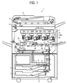
- FIG. 1 a configuration and operation of an image forming apparatus 1 according to an embodiment is described below.
- reference numerals 1 represents an image forming apparatus, which in the present embodiment is a tandem-type multicolor copier
- 2 represents a writing device to emit laser beams according to image data
- 3 represents a document feeder to send a document D to a document reading unit 4 that reads image data of the document D
- 7 represents a sheet feeding tray containing sheets P of recording media (i.e., transfer paper)
- 8 represents sheet feeding rollers
- 9 represents a registration roller pair (i.e., a timing roller pair) to adjust the timing to transport the sheet P
- 10Y, 10M, 10C, and 10BK represent process cartridges to form yellow, magenta, cyan, and black toner images, respectively.
- reference numerals 17 represents an intermediate transfer belt
- 18 represents a secondary-transfer bias roller to transfer a toner image from the intermediate transfer belt 17 onto the sheet P
- 19 represents a belt cleaning device to clean the intermediate transfer belt
- 20 represents primary-transfer bias rollers to transfer the toner images from photoconductor drums 12 onto the intermediate transfer belt 17 in superimposed manner
- 30 represents a fixing device to fix the toner image on the sheet P
- 50Y, 50M, 50C, and 50BK represent toner cartridges (i.e., toner containers) to contain yellow, magenta, cyan, and black toners, respectively.
- FIG. 2 is also referred to when image forming process performed on the photoconductor drums 12 are described.
- conveyance rollers transport documents D set on a document table in a direction indicated by an arrow onto an exposure glass 5 of the document reading unit 4. Then, the document reading unit 4 optically reads image data of the document D set on the exposure glass 5.
- the document reading unit 4 scans the image on the document D with light emitted from an illumination lamp.
- the light reflected by a surface of the document is imaged on a color sensor via mirrors and lenses.
- the color sensor reads the multicolor image data of the document D for each of decomposed colors of red, green, and blue (RGB) and convert the image data into electrical image signals.
- RGB red, green, and blue
- an image processor performs image processing (e.g., color conversion, color calibration, and spatial frequency adjustment) according to the image signals, and thus image data of yellow, magenta, cyan, and black are obtained.
- the yellow, magenta, cyan, and black image data is transmitted to the writing device 2 (i.e., an exposure device).
- the writing device 2 directs laser beams L (illustrated in FIG. 2 ) to the surfaces of the photoconductor drums 12 according to the image data of respective colors.
- the photoconductor drums 12 in the four process cartridges 10 rotate counterclockwise in FIG. 1 .
- the surface of the photoconductor drum 12 is charged by a charging device 14 (i.e., a charging roller) uniformly at a position facing the charging device 14 (charging process).
- the surface of the photoconductor drum 12 is charged to a predetermined electrical potential.
- the surface of the photoconductor drum 12 thus charged reaches a position to receive the laser beam L (illustrated in FIG. 2 ).
- the writing device 2 emits the laser beams L according to the image data from four light sources.
- the four laser beams L pass through different optical paths for yellow, magenta, cyan, and black.
- the laser beam L corresponding to the yellow component is directed to the photoconductor drum 12 in the process cartridge 10Y that is the first from the left in FIG. 1 among the four process cartridges 10.
- a polygon mirror that rotates at high velocity deflects the laser beam L for yellow in a direction of a rotation axis of the photoconductor drum 12 for yellow (main scanning direction) so that the laser beam L scans the surface of the photoconductor drum 12 for yellow.
- an electrostatic latent image for yellow is formed on the photoconductor drum 12 charged by the charging device 14.
- the laser beam L corresponding to the magenta component is directed to the photoconductor drum 12 in the process cartridge 10M, which is the second from the left in FIG. 1 , thus forming an electrostatic latent image for magenta thereon.
- the laser beam L corresponding to the cyan component is directed to the photoconductor drum 12 of the process cartridge 10C, which is the third from the left in FIG. 1 , thus forming an electrostatic latent image for cyan thereon.
- the laser beam L corresponding to the black component is directed to the fourth photoconductor drum 12 from the left in FIG. 1 , thus forming an electrostatic latent image for black thereon.
- each developing device 13 supplies toner of the corresponding color to the photoconductor drum 12 to develop the latent image on the photoconductor drum 12 into a single-color toner image (development process).
- the surface of the photoconductor drum 12 reaches a position (a primary transfer nip) facing the intermediate transfer belt 17, serving as the image bearer as well as an intermediate transfer member.
- the primary-transfer bias rollers 20 are disposed at the positions where the respective photoconductor drums 12 face the intermediate transfer belt 17 and in contact with an inner surface of the intermediate transfer belt 17. At these positions, the toner images on the respective photoconductor drums 12 of the process cartridges 10 are sequentially transferred and superimposed one on another on the intermediate transfer belt 17 in a primary-transfer process.
- a primary transfer bias which is different in polarity from the toner, is applied to each primary-transfer bias roller 20.
- each photoconductor drum 12 reaches a position facing a cleaning blade 15 (i.e., a cleaning section).
- the cleaning blade 15 collects toner (untransferred toner) remaining on the photoconductor drum 12 (a cleaning process).
- each photoconductor drum 12 passes through a discharge device, and thus a sequence of image forming processes performed on each photoconductor drum 12 is completed.
- the surface of the intermediate transfer belt 17 carrying the superimposed toner image moves counterclockwise and reaches the position facing the secondary-transfer bias roller 18.
- the secondary-transfer bias roller 18 transfers the multicolor toner image from the intermediate transfer belt 17 onto the sheet P (secondary transfer process).
- the surface of the intermediate transfer belt 17 reaches a position facing the belt cleaning device 19.
- the belt cleaning device 19 collects untransferred toner remaining on the intermediate transfer belt 17. Thus, a sequence of transfer processes performed on the intermediate transfer belt 17 is completed.
- the sheet P is transported from one of the sheet feeding trays 7 via the registration roller pair 9 and the like to the secondary transfer nip between the intermediate transfer belt 17 and the secondary-transfer bias roller 18.
- the sheet feeding roller 8 sends out the sheet P from the sheet feeding tray 7, and the sheet P is then guided by a sheet guide to the registration roller pair 9.
- the registration roller pair 9 forwards the sheet P to the secondary transfer nip, timed to coincide with the arrival of the multicolor toner image on the intermediate transfer belt 17.
- the fixing device 30 includes a fixing roller and a pressure roller pressing against each other. In a nip therebetween, the multicolor image is fixed on the sheet P.
- the process cartridge 10 i.e., an image forming unit
- an image forming unit is described in further detail below.
- the process cartridge 10 includes the photoconductor drum 12 serving as the image bearer, the charging device 14 to charge the surface of the photoconductor drum 12, the developing device 13 to develop the latent image on the photoconductor drum 12, the cleaning blade 15 to clean the photoconductor drum 12, and a lubricant supply device 16.
- Each process cartridge 10 is removably mountable in a body of the image forming apparatus 1 (hereinafter "apparatus body").
- process cartridges 10Y, 10C, 10M, and 10BK are similar in configuration, and thus the subscripts Y, C, M, and BK are omitted from the process cartridges 10, the photoconductor drums 12, and the developing devices 13 in FIGS. 2 and 3 and descriptions below for simplicity.
- the photoconductor drum 12 used in the present embodiment is an organic photoconductor charged to a negative polarity and includes a photosensitive layer on a drum-shaped conductive support base.
- the photoconductor drum 12 is multilayered, and a base coat serving as an insulation layer, the photosensitive layer, and a protection layer (surface layer) are formed sequentially on the support base.
- the photosensitive layer includes a charge generation layer and a charge transport layer.
- a conductive material having a volume resistivity of 10 10 ⁇ cm or lower is usable.
- the photoconductor drum 12 is rotated in a predetermined direction (counterclockwise in FIG. 2 , as indicated by arrow Y1) by a first driving motor 61 serving as a first driver. It is to be noted that, in Embodiment 1, the first driving motor 61 also rotates the charging device 14 (the charging roller), a lubricant supply roller 16a, and a conveying screw 15b, via a train of gears, in the directions indicated by arrows in FIG. 2 .
- the charging device 14 is a roller having an elastic layer of moderate resistivity overlying an outer circumference of a conductive metal core.
- the charging device 14 is disposed to contact the photoconductor drum 12 at a position downstream from the lubricant supply device 16 in the direction of rotation of the photoconductor drum 12 indicated by arrow Y1.
- the charging device 14 uniformly charges the surface of the photoconductor drum 12 facing the charging device 14.
- the charging device 14 is pressed against the photoconductor drum 12 in Embodiment 1, in another embodiment, the charging device 14 is disposed across a minute gap from the photoconductor drum 12.
- the cleaning blade 15 is disposed downstream from the lubricant supply device 16 in the direction of rotation of the photoconductor drum 12.
- the cleaning blade 15 is made of or includes rubber, such as urethane rubber, and contacts or abuts on the surface of the photoconductor drum 12, at a predetermined angle and with a predetermined pressure. With this arrangement, substances such as toner and dust adhering to the surface of the photoconductor drum 12 are mechanically scraped off and are collected in the process cartridge 10.
- the conveying screw 15b transports the toner collected in the process cartridge 10, as waste toner, to a waste-toner container removably attached to the back side of the apparatus body, which is on the back side of the paper on which FIG. 1 is drawn.
- the substances adhering to the photoconductor drum 12 include paper dust resulting from the sheet P, discharge products generated on the photoconductor drum 12 during discharge by the charging device 14, additives to the toner, and the like in addition to the untransferred toner.
- the cleaning blade 15 according to Embodiment 1 serves as a leveling blade to level off, to a suitable layer thickness, the lubricant supplied to the photoconductor drum 12 by the lubricant supply roller 16a.
- the lubricant supply device 16 includes a solid lubricant 16b, the lubricant supply roller 16a (e.g., a brush roller) to slide on the photoconductor drum 12 and the solid lubricant 16b, a holder 16e to hold the solid lubricant 16b, and a compression spring 16c to bias the holder 16e, together with the solid lubricant 16b, to the lubricant supply roller 16a.
- the lubricant supply roller 16a e.g., a brush roller
- the lubricant supply device 16 supplies the lubricant to the photoconductor drum 12. Then, the cleaning blade 15 disposed downstream from the lubricant supply device 16 levels the lubricant, into a thin layer, on the photoconductor drum 12.
- the developing device 13 includes a developing roller 13a, serving as a developer bearer, disposed across a gap (i.e., a development gap) of predetermined size from the photoconductor drum 12.
- a developing roller 13a serving as a developer bearer
- the developing range or a developing nip
- the developing device 13 contains two-component developer G including toner particles T (also "toner T") and carrier particles C 1 (also "carrier C1").
- the developing device 13 develops the latent image on the photoconductor drum 12 into a toner image.
- the configuration and operation of the developing device 13 are described in further detail later.
- the toner cartridges 50Y, 50M, 50C, and 50BK (also collectively “toner cartridges 50") contain respective color toners T supplied into the developing devices 13. Specifically, according to the toner concentration (the ratio of toner T in developer G) detected by a magnetic sensor 13h (illustrated in FIG. 3 ) disposed in the developing device 13, a toner supply device supplies the toner T from the toner cartridge 50 via a supply inlet 13e (illustrated in FIG. 3 ) to the developing device 13 as required.
- the data according to which the toner T is supplied is not limited to the toner concentration.
- the toner T can be supplied according to image density calculated from the reflectance of the toner image on the photoconductor drum 12 or the intermediate transfer belt 17.
- the toner T can be supplied according to a combination of such data.
- the toner supply device to supply toner to the developing device 13
- a configuration in which a conveying auger transports toner, a configuration in which a screw pump transports toner together with air, and the like can be used.
- the four toner cartridges 50Y, 50M, 50C, and 50BK are mountable in and removable from the apparatus body from the front side of the paper on which FIG. 1 is drawn, that is, the side on which a control panel is disposed. When the toner cartridge 50 becomes empty, the toner cartridge 50 is replaced.
- the developing device 13 is described in further detail below.
- the developing device 13 includes the developing roller 13a serving as a developer bearer, first and second conveying screws 13b1 and 13b2 (screw augers) serving as developer conveyors, and a doctor blade 13c serving as a developer regulator.
- a casing 13k of the developing device 13 has an opening to partly expose the developing roller 13a to the photoconductor drum 12.
- the developing roller 13a includes a sleeve 13a2 that is a cylindrical, nonmagnetic component made of aluminum, brass, stainless steel, or conductive resin.
- the sleeve 13a2 is rotated by a second driving motor 62 serving as a second driver via a driving gear that meshes with a gear attached to a shaft of the second driving motor 62.
- a magnet 13a1 is disposed not to rotate with a shaft thereof lightly fitted in a side plate.
- the magnet 13a1 generates multiple magnetic poles around the circumference of the sleeve 13a2.
- the developer G carried on the developing roller 13a is transported in the direction indicated by arrow Y2 in FIG. 2 to the doctor blade 13c (the developer regulator).
- the amount of the developer G on the developing roller 13a is adjusted by the doctor blade 13c to a suitable amount.
- the amount of developer G scooped onto a unit area is about 30 mg/cm 2 to 38 mg/cm 2 .
- the developer G is transported to the developing range facing the photoconductor drum 12.
- toner in the developer G is attracted to the latent image on the photoconductor drum 12 due to the magnetic field (generated with the difference between the latent image potential on the photoconductor drum 12 and the developing bias applied to the developing roller 13a) in the developing range.
- the developing bias is applied from a power source 68 (i.e., a developing bias source) serving as a developing bias source.
- the doctor blade 13c serving as the developer regulator is a shaped like a place made of a nonmagnetic material and disposed facing the top side of the developing roller 13a in FIG. 2 .
- a distance (i.e., the size of a doctor gap) between the doctor blade 13c and the developing roller 13a is about 0.2 mm to 0.3 mm.
- the developing roller 13a is rotated in a predetermined direction (clockwise in FIG. 2 ) by the second driving motor 62 (the second driver) as indicated by arrow Y2. In other words, both of the photoconductor drum 12 and the developing roller 13a rotate downward at the position (the development gap) facing each other.
- the linear speed A means the linear speed of the outer circumference of the photoconductor drum 12 and about 415 mm/s, for example.
- the linear speed B is the speed of the outer circumference of the developing roller 13a at the position facing the photoconductor drum 12, and the linear speed B is about 623 mm/s, for example.
- the ratio of the linear speed B relative to the linear speed A (hereinafter "linear speed ratio X”) is about 1.5 in Embodiment 1.
- Preferable images can be developed in the developing process in which the developing roller 13a rotates faster than the photoconductor drum 12 in the developing range.
- the second driving motor 62 also rotates, via a train of gears, the first and second conveying screws 13b1 and 13b2 in the directions indicated by respective arrows in FIG. 2 .
- the second driving motor 62 is in a driving system independent of a driving system including the first driving motor 61.
- the second driving motor 62 is a variable-speed motor, and the rotation speed thereof is changed in two steps in Embodiment 1.
- the first conveying screw 13b1 and the second conveying screw 13b2 stir and mix the developer G contained in the developing device 13 while transporting the developer G horizontally in the longitudinal direction or the axial direction, which is perpendicular to the surface of the paper on which FIG. 2 is drawn and lateral in FIG. 3 .
- the first conveying screw 13b1 is disposed facing the developing roller 13a.
- the first conveying screw 13b1 supplies the developer G to the developing roller 13a as indicated by hollow arrows illustrated in FIG. 3 at the position corresponding to a scooping pole while transporting the developer G to the left in Section (a) of FIG. 3 as indicated by a broken arrow illustrated in Section (a).
- the second conveying screw 13b2 is disposed below the first conveying screw 13b1 and faces the developing roller 13a. After image development, the developer G is separated by a developer release pole from the developing roller 13a in the direction indicated by hollow arrows, and the second conveying screw 13b2 transports the developer G that has left the developing roller 13a to the right in Section (b) of FIG. 3 as indicated by a broken arrow illustrated therein.
- the developer G is transported from the downstream side of the conveyance compartment in which the first conveying screw 13b1 is disposed (hereinafter “first conveyance compartment 31") through a first communication opening 13g to the conveyance compartment in which the second conveying screw 13b2 is disposed (hereinafter “second conveyance compartment 32").
- the second conveying screw 13b2 transports the developer G downstream in the second conveyance compartment 32 and forwards the developer G through a second communication opening 13f to the upstream side of the first conveyance compartment 31 (as indicated by alternate long and short dashed arrow).
- the first and second conveying screws 13b1 and 13b2 are disposed so that rotation axes thereof are substantially horizontal similar to the developing roller 13a and the photoconductor drum 12.
- Each of the first and second conveying screws 13b1 and 13b2 includes a screw shaft and a spiral blade winding around the screw shaft.
- An inner wall of the developing device 13 separates the first conveyance compartment 31 (or a supply compartment) in which the first conveying screw 13b1 is disposed from the second conveyance compartment 32 (or a collecting compartment) in which the second conveying screw 13b2 is disposed.
- the downstream side of the second conveyance compartment 32 in which the second conveying screw 13b2 is disposed, communicates with the upstream side of the first conveyance compartment 31 through the second communication opening 13f.
- the developer G that is not supplied to the developing roller 13a accumulates adjacent to the second communication opening 13f and then transported therethrough to the upstream side of the first conveyance compartment 31.
- the downstream side of the first conveyance compartment 31 communicates with the upstream side of the second conveyance compartment 32 through the first communication opening 13g.
- the developer G that has not supplied to the developing roller 13a falls under the weight thereof through the first communication opening 13g to the upstream side of the second conveyance compartment 32.
- a paddle or a screw winding in the opposite direction can be disposed on the downstream side of the second conveyance compartment 32 (at a position facing the second communication opening 13f) to facilitate developer conveyance through the second communication opening 13f (movement against the gravity from the second conveyance compartment 32 to the first conveyance compartment 31).
- This configuration provides a circulation passage through which the developer G is circulated in the longitudinal direction by the first and second conveying screws 13b1 and 13b2 in the developing device 13. That is, when the developing device 13 is activated, the developer G contained therein flows in the developer circulation direction indicated by the broken arrows illustrated in FIG. 3 .
- Separating the first conveyance compartment 31 (the supply compartment), in which the first conveying screw 13b1 supplies the developer G to the developing roller 13a, from the second conveyance compartment 32 (the collecting compartment), to which the developer G is collected from the developing roller 13a by the second conveying screw 13b2, can reduce density unevenness of toner images on the photoconductor drum 12.
- the magnetic sensor 13h to detect the toner concentration in the developer G circulated in the developing device 13 is disposed below the first conveying screw 13b1, on the upstream side of the first conveyance compartment 31. Based on the toner concentration detected by the magnetic sensor 13h, fresh toner T is supplied from the toner cartridge 50 to the developing device 13 through the supply inlet 13e disposed adjacent to the second communication opening 13f.
- the supply inlet 13e is located above the upstream side of the first conveyance compartment 31, in which the first conveying screw 13b1 is disposed, and away from the developing range, that is, disposed outside the area occupied by the developing roller 13a in the longitudinal direction.
- the developing device 13 (or the process cartridge 10) according to Embodiment 1 includes a developer supply inlet 13m to supply the developer G into the developing device 13.
- the developer supply inlet 13m is disposed above the second conveyance compartment 32, in which the second conveying screw 13b2 is disposed, and away from the developing range to the front side of the image forming apparatus 1 (on which a door 100 illustrated in FIG. 4 is disposed).
- the developer supply inlet 13m is sealed with a cap except a period during which the two-component developer G is supplied to the developing device 13.
- a service person or an operator fills the developing device 13 with the developer G as follows. Open the door 100 (i.e., an apparatus body cover), which is hinged, in the directions illustrated in FIG. 4 in a state in which the developing device 13 is in the image forming apparatus 1. Then, the process cartridges 10Y, 10M, 10C, and 10BK are exposed. Couple a funnel 71 (a relay member) to the developer supply inlet 13m of the developing device 13 from outside. Further, couple the developer container 70 (containing fresh developer G) to the funnel 71 from outside. Supply the developer G from the developer container 70 via the funnel 71 into the developing device 13 while driving the developing device 13 (with the second driving motor 62).
- a funnel 71 a relay member
- FIG. 4 illustrates supplying the developer G to the developing device 13 of the process cartridge 10BK of the four process cartridges 10Y, 10C, 10M and 10BK, the developer G is supplied to the other process cartridges 10Y, 10C, and 10M in similar manner.
- Supplying the developer G to the empty developing device 13 occurs when a new developing device 13 (a new process cartridge) is installed the image forming apparatus 1, when the degraded developer G (degraded carrier C1) is discharged from the developing device 13 in use and replaced with fresh developer G, and the like.
- replacement of developer requires removal of the degraded developer G from the developing device 13 in use.
- Such operation can be done manually after the developing device 13 (the process cartridge 10) in use is removed from the image forming apparatus 1.
- the developing device 13 includes an openable and closable developer outlet (to be coupled to a waste developer container)
- the developer G can be automatically discharged while driving the developing device 13 after the developer outlet is opened.
- such developer supply is a special work performed in a state in which the door 100 is open, and the service person or the like inputs a special key on a control panel of the image forming apparatus 1 to perform this work.
- Embodiment 1 as described above, although the developing device 13 (the second driving motor 62) is driven during the developer supply operation, the photoconductor drum 12 (the first driving motor 61) is not driven. That is, during the developer supply operation, rotation of the photoconductor drum 12 is stopped, and only the developing device 13 (the developing roller 13a and the first and second conveying screws 13b1 and 13b2 in particular) is driven.
- This configuration inhibits curl or noise of the cleaning blade 15 that slides on the photoconductor drum 12 and alleviates acceleration of wear of the photoconductor drum 12, the cleaning blade 15, and the charging device 14.
- the door 100 is open and the interior of the image forming apparatus 1 is exposed during the developer supply operation. Accordingly, application of high voltage, such as the developing bias applied to the developing roller 13a and the charging bias applied to the charging device 14, is inhibited to eliminate risks for the operator to touch a component to which high voltage is applied. If the photoconductor drum 12 is rotated in a state in which the developing bias and the charging bias are turned off, there arise inconveniences. For example, the toner in the developer G borne on the developing roller 13a adheres to the surface of the photoconductor drum 12 as background toner stain, and the toner concentration in the developer G in the developing device 13 decreases. If the background toner stain scatters from the photoconductor drum 12, the interior of the apparatus is soiled with toner. Accordingly, stopping the photoconductor drum 12 during the developer supply operation is advantageous.
- high voltage such as the developing bias applied to the developing roller 13a and the charging bias applied to the charging device 14
- Embodiment 1 in a case where first driving (i.e., a first driving mode or a developer supply mode) is executed in an idle time (non-image formation period) during which the image forming apparatus 1 does not perform the standard image forming process on the photoconductor drum 12, the image forming apparatus 1 executes second driving (or operates in a second driving mode) for a predetermined period D2.
- the controller 60 controls the first driving motor 61 (the first driver) and the second driving motor 62 (the second driver) to drive the developing roller 13a with driving of the photoconductor drum 12 (the image bearer) stopped.
- the image forming apparatus 1 executes the second driving for the predetermined period D2.
- the controller 60 controls the first driving motor 61 and the second driving motor 62 to make the linear speed ratio X (the ratio B/A of the linear speed B of the developing roller 13a relative to the linear speed A of the photoconductor drum 12 in the development gap) smaller than 1.
- the linear speed ratio X is returned to the standard value (1.5 in Embodiment 1). Then, the process control (adjustment of image forming conditions) or standard image formation (printing operation) is performed.
- the first driving is the developer supply mode, in which the developer G is supplied into the empty or almost empty developing device 13, as described above with reference to FIG. 4 , in the state in which the process cartridge 10 (including the developing device 13 and the photoconductor drum 12) is mounted in the image forming apparatus 1.
- the first driving the developer supply mode
- the second driving motor 62 drives the developing roller 13a to rotate at a normal speed.
- normal speed used here means a linear speed or the number of revolutions for standard image formation.
- the linear speed B of the developing roller 13a at that time is set at about 623 mm/s.
- the controller 60 controls the power sources 66 not to apply the charging bias to the charging device 14 (e.g., the charging roller) and not to apply developing bias to the developing roller 13a.
- Other biases, such as the transfer bias, are turned off similarly.
- the first driving (the developer supply mode) is executed for a predetermined period D1, which is preliminarily set to a constant length of time (about 30 seconds in Embodiment 1) based on the capacity of the developer container 70, the speed at which the first and second conveying screws 13b1 and 13b2 circulate the developer G in the developing device 13, and the like.
- the second driving is executed for the predetermined period D2 (about 10 seconds in Embodiment 1) immediately after the first driving.
- the controller 60 controls the first driving motor 61 and the second driving motor 62 to rotate the developing roller 13a at a linear speed B' lower than the linear speed A of the photoconductor drum 12.
- the photoconductor drum 12 rotates at the linear speed A (about 415 mm/s) similar the speed for standard image formation, and the developing roller 13a rotates at a lower speed (the linear speed B') of about 265 mm/s.
- the ratio of the linear speed B' to the linear speed A is about 0.64, for example.
- the controller 60 controls the power sources 66 and 68 to apply the charging bias to the charging device 14 (e.g., the charging roller) and to apply developing bias to the developing roller 13a. This operation inhibits the toner T and the carrier C1 included in the developer G carried on the developing roller 13a from adhering to the photoconductor drum 12.
- development gap size PG the size of the development gap
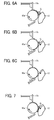
- the developer G tends to accumulate on the upstream side of the development gap in the direction of rotation of the developing roller 13a as illustrated in FIG. 6A .
- p/PG the ratio of the scooped developer amount p to the development gap size PG
- both of the developing roller 13a and the photoconductor drum 12 rotate at the linear speed for standard printing operation (the linear speed ratio therebetween is 1 or greater), it is possible that the developer G accumulating on the upstream side of the development gap is compressed in the development gap and firmly adheres to the developing roller 13a or the photoconductor drum 12 as illustrated in FIG. 7 .
- the developer firmly adhering to the developing roller 13a, the photoconductor drum 12, or both can result in substandard images with streaks and periodic uneven image density.
- Embodiment 1 even when the developer G accumulates on the upstream side of the development gap during the first driving, the developer G enters the development gap little by little as illustrated in FIG. 6B since the developing roller 13a rotates at the linear speed B' lower than the linear speed A of the photoconductor drum 12 in the second driving. Thus, the developer G is less likely to firmly adhere to the developing roller 13a or the photoconductor drum 12.
- the state of the developer G in the developing device 13 returns to a state suitable for standard image formation.
- the accumulation of the developer G caused by the first driving is resolved to a degree suitable for standard image formation. That is, the second driving is for removing the accumulating developer.
- the state of the developer G returns to the state suitable for standard image formation as illustrated in FIG. 6C .
- FIG. 8 presents results of observation with eyes of adhesion of developer in each linear speed combination. The experiment was executed under a condition to cause the accumulation of developer illustrated in FIG. 6A .
- "YES” means that adhesion of developer was observed
- "NO” means that adhesion of developer was not observed.
- the result illustrated in FIG. 8 ascertains that, even when the developer accumulates in the first driving as illustrated in FIG. 6A , adhesion of developer to the developing roller 13a and the photoconductor drum 12 is inhibited by rotating the developing roller 13a at the linear speed B' lower than the linear speed A of the photoconductor drum 12 after the first driving.
- a point of the second driving is rotting the developing roller 13a at the linear speed B' lower than the linear speed A of the photoconductor drum 12. Accordingly, it is conceivable that, in the second driving, the rotation speed of the photoconductor drum 12 in the development gap can be increased from the linear speed A for standard image formation, and the rotation speed of the developing roller 13a can be similar to the linear speed B for standard image formation. In this case, however, it is necessary that the first driving motor 61 has a capability to increase the rotation speed of the photoconductor drum 12 from the rotation speed A for standard image formation, and the size and the cost of the first driving motor 61 increase.
- the rotation speed of the photoconductor drum 12 in the development gap is set to the linear speed A for standard image formation, and the rotation speed of the developing roller 13a is reduced from the linear speed B for standard image formation. Accordingly, without increasing the size and the cost of the first driving motor 61 and the second driving motor 62, adhesion of developer to the developing roller 13a and the photoconductor drum 12 is inhibited.
- FIG. 9 is a graph illustrating changes in the driving torque of the second driving motor 62, which drives the developing device 13, after the second driving is started.
- the driving torque is converted from the detection result generated by an electrical-current detector 63 serving as a torque detector, which detects the value of electrical current flowing to the second driving motor 62.
- a solid graph represents changes in the driving torque in a state in which the developer G is contained in the developing device 13 (after the first driving is executed), and a broken graph represents changes in the driving torque in a state in which the developer G is not contained in the developing device 13 (empty state without supply of developer), as a comparative state.
- the driving torques represented by the solid graph and the broken graph are high since a large starting current (electrical current) or a large starting torque is generated immediately after the second driving motor 62 is started.
- the driving torque in the developing device 13 without developer G decreases and becomes stable.
- a period N is a time difference between Time point T2 and Time point T3, and it takes the period N to resolve the accumulation of the developer G illustrated in FIG. 6A .
- the inventors measured the changes in the driving torque (illustrated in FIG. 9 ) of the developing device 13 in accordance with each of the experimental conditions presented in FIG. 8 .
- the period N is relatively long under the conditions to cause firm adhesion of developer. Under the conditions that do not cause firm adhesion of developer, the period N is shorter and close to zero.
- the controller 60 controls the first driving motor 61 and the second driving motor 62 so that the linear speed ratio X at the driving start of the developing roller 13a and the photoconductor drum 12 is similar to the ratio for image formation (about 1.5, for example).
- the first driving is executed only when developer is supplied to the developing device 13, and the second driving is subsequently executed in that case.
- the first driving is executed only when developer is supplied to the developing device 13, and the second driving is subsequently executed in that case.
- the first driving nor the second driving is executed, and the photoconductor drum 12 and the developing roller 13a (the developing device 13) are driven at the normal linear speed ratio.
- the first driving and the second driving are not executed regarding the process cartridges 10Y, 10M, and 10C.
- the photoconductor drum 12 and the developing roller 13a (the developing device 13) in each of the process cartridges 10Y, 10M, and 10C are started at the normal linear speed ratio.
- the photoconductor drum 12 and the developing roller 13a are driven at the normal linear speed ratio in each of the process cartridges 10Y, 10M, and 10C, which are not the targets of developer supply.
- Such driving control is advantageous in that the first driving and the second driving are executed when unnecessary.
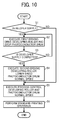
- FIG. 10 is a flowchart of the above-descried driving control in supplying developer to the developing device 13.
- the controller 60 determines whether or not the developer G is supplied to the developing device 13. For example, to determine whether or not the developing device 13 is in the state to receive supply of the developer G, a detector detects whether or not the developer container 70 (and the funnel 71) is connected to the developer supply inlet 13m of the developing device 13.
- the apparatus executes the first driving (operates in the developer supply mode) until the controller 60 determines that the developer supply is completed at S3. Specifically, in Embodiment 1, the controller 60 executes the first driving for the predetermined period D1.
- the controller 60 executes the second driving (the accumulating developer removal mode) for the predetermined period D2.
- the developing roller 13a is driven at the linear speed B' lower than the speed for image formation, and the photoconductor drum 12 is driven at the normal speed for image formation.
- the controller 60 executes the process control (image forming condition adjustment) while driving the developing device 13 and the photoconductor drum 12 at the respective normal speeds for image formation.
- the process control is typically executed after developer supply and the like and includes calibration of output of an optical sensor to detect a patch pattern on the photoconductor drum 12 or the intermediate transfer belt 17 and adjustment of the charging bias and the developing bias.
- standard image formation (standard printing operation) is performed while driving the developing device 13 and the photoconductor drum 12 at the respective normal speeds.
- controller 60 determines that the developing device 13 is not in the state to receive supply of the developer G (No at S1), the steps S2 through S4 are not executed, but the steps S5 and S6 are executed.
- the predetermined period D2 during which the second driving is executed is changed in accordance with changes in the predetermined period D 1 during which the first driving is executed.
- the predetermined period D 1 of the first driving When the predetermined period D 1 of the first driving is longer, the amount of accumulating developer illustrated in FIG. 6A is greater compared with a case where the predetermined period D 1 is shorter. Accordingly, the predetermined period D2 is increased to reliably remove the accumulating developer in a longer time.
- the predetermined period D 1 is set to a longer time, and the predetermined period D2 of the second driving is set to a longer time accordingly.
- the predetermined period D2 of the second driving is preliminarily set to a constant value.
- the controller 60 can be configured to complete the second driving when the driving torque detected by the electrical-current detector 63 (the torque detector) illustrated in FIG. 2 falls to or below a threshold.
- the electrical-current detector 63 indirectly detects the magnitude of torque applied to the second driving motor 62 (the second driver) based on changes in the current flowing to the driving motor 62. As described above with reference to FIG. 9 , whether or not the accumulating developer is removed is known from the changes in the driving torque applied to the second driving motor 62. This configuration is advantageous in efficiently and reliably removing the developer accumulating on the upstream side of the development gap.
- an accumulating developer detector such as a photosensor can be used to directly detect the developer accumulating on the upstream side of the development gap, and the controller 60 can be configured to complete the second driving based on the detection result generated by the accumulating developer detector.
- the second driving is executed for the predetermined period D2 subsequent to the first driving.
- the first driving motor 61 and the second driving motor 62 are controlled to make the linear speed ratio X (B/A, the ratio of the linear speed B of the developing roller 13a relative to the linear speed A of the photoconductor drum 12 in the development gap) smaller than 1.
- Embodiment 2 is described below with reference to FIGS. 11 through 13 .
- FIG. 11 is a timing chart of actions when developer is supplied to the developing device 13 and the cleaning blade 15 is new in the image forming apparatus 1 according to Embodiment 2.
- FIG. 11 corresponds to FIG. 5 of Embodiment 1.
- FIG. 12 is a timing chart of actions when developer is not supplied to the developing device 13 and the cleaning blade 15 is new in the image forming apparatus 1 according to Embodiment 2.
- FIG. 12 corresponds to FIG. 5 of Embodiment 1.
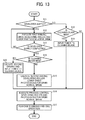
- FIG. 13 is a flowchart of driving control according to Embodiment 2 including the actions illustrated in FIGS. 11 and 12 .
- FIG. 13 corresponds to FIG. 10 of Embodiment 1.
- the driving control according to Embodiment 2 is different from that of Embodiment 1 in that toner is input to the cleaning blade 15 when the cleaning blade 15 is new.
- the image forming apparatus 1 according to Embodiment 2 has a configuration similar to that according to Embodiment 1. Similar to Embodiment 1, after executing the first driving (the developer supply mode), the controller 60 executes the second driving (the accumulating developer removal mode).
- the image forming apparatus 1 includes a data reader 64 (illustrated in FIG. 2 ), serving as a new-blade detector to detect whether or not the cleaning blade 15 is new.
- the cleaning blade 15 contacts or abuts against the surface of the photoconductor drum 12 at a predetermined angle and a predetermined pressure to remove toner adhering to the photoconductor drum 12.
- the data reader 64 serving as the new-blade detector is configured to read data stored in an ID (identity) chip disposed in the process cartridge 10.
- the ID chip stores various types of data, such as usage history and date of manufacture, of the process cartridge 10. From the read data, the controller 60 determines whether or not the cleaning blade 15 is new.
- the cleaning blade 15 being new means that the cleaning blade 15 is not used at all to clean the photoconductor drum 12, or has been used only for a short length of time.
- toner input operation the cleaning blade 15
- blade protection mode the developing device 13 develops a predetermined latent image on the photoconductor drum 12, and then the cleaning blade 15 collects the toner from the developed image.
- the writing device 2 forms, on the photoconductor drum 12, a predetermined electrostatic latent image for the blade protection mode.
- the developing device 13 develops the predetermined electrostatic latent image into a toner image, and the toner image is not transferred onto the intermediate transfer belt 17 in the primary transfer nip but supplied to the cleaning blade 15. Accordingly, during the toner input operation (the blade protection mode), the transfer bias for the primary-transfer bias roller 20 is turned off. Alternatively, a bias identical in polarity to toner is applied to the primary-transfer bias roller 20.
- Embodiment 2 in the toner input operation (the blade protection mode) executed simultaneously with the second driving, a solid image of A4 size (320 mm ⁇ 210 mm) is regarded as a unit toner pattern (unit toner image), and 15 toner patterns are formed on the photoconductor drum 12 to input a sufficient amount of toner to the edge of the cleaning blade 15 entirely in the width direction of the cleaning blade 15.
- the operation "toner input operation” is performed because the cleaning blade 15 being new contacts the photoconductor drum 12 too tightly. If the second driving is executed and the photoconductor drum 12 rotates in this state, the cleaning blade 15 curls or noise of machine vibration is generated.
- Embodiment 2 when the cleaning blade 15 is new and the photoconductor drum 12 rotates in the second driving, the toner image is formed so that the toner reaches the edge (abutting on the photoconductor drum 12) of the cleaning blade 15. Therefore, the toner is retained at the edge of the cleaning blade 15 and serves as lubricant interposed between the cleaning blade 15 and the photoconductor drum 12. Accordingly, curl of the cleaning blade 15 and noise of machine vibration are alleviated. That is, the toner input operation is executed to protect the cleaning blade 15.
- Embodiment 2 in a case where the first driving (the developer supply mode) is not executed and the data reader 64 (the new-blade detector) detects that the cleaning blade 15 is new, the second driving (the accumulating developer removal mode) is not executed, and the operation "toner input operation" (the blade protection mode) is executed with the linear speed ratio X set to a ratio X2 (about 1.5 in Embodiment 2) similar to the ratio for standard image formation.
- Such control is performed because reducing the linear speed ratio X is unnecessary when the second driving is not executed.
- the linear speed ratio X is similar to that for standard image formation, the developing capability of the developing device 13 (the toner adhesion amount per unit area of the toner image on the photoconductor drum 12) is higher, and forming the toner image for the blade protection mode becomes easier.
- Embodiment 2 in the toner input operation (the blade protection mode) executed without the second driving, a solid image of A4 size (320 mm ⁇ 210 mm) is regarded as a unit toner pattern, and 6 toner patterns are formed on the photoconductor drum 12 to input a sufficient amount of toner to the edge of the cleaning blade 15 entirely in the width direction of the cleaning blade 15.
- Embodiment 2 when “A1” represents the total area of the patters (toner images) developed in the toner input operation executed simultaneously with the second driving, “A2” represents the total area of the patters (toner images) developed in the toner input operation executed without the second driving, “X1” represents the linear speed ratio X during the second driving (about 0.64 in Embodiment 2), and “X2” represents the linear speed ratio X for standard image formation, A1 ⁇ A2 ⁇ (X2/X1) is satisfied.
- the number of the toner patterns is 15 and the total area A1 of the toner patters is 320 mm ⁇ 210 mm ⁇ 15.
- the number of the toner patterns is 6 and the total area A2 of the toner patters is 320 mm ⁇ 210 mm ⁇ 6.
- the linear speed ratio X of the developing roller 13a relative to the photoconductor drum 12 is set to the ratio X1 (lower than the ratio X2 for standard image formation), and the developing capability (the toner adhesion amount per unit area on the photoconductor drum 12) is lower, and the amount of toner supplied to the cleaning blade 15 decreases.
- the number of toner patterns is increased to compensate for the decrease in the toner adhesion amount due to the decrease in the linear speed ratio X in the second driving.
- a sufficient amount of toner is supplied to the cleaning blade 15, curl of the cleaning blade 15 and noise of machine vibration are alleviated.
- FIG. 13 is a flowchart of the above-descried driving control according to Embodiment 2. It is to be noted that descriptions of steps similar to those in FIG. 10 of Embodiment 1 are simplified or omitted to avoid redundancy.
- the controller 60 determines whether or not the developing device 13 is in the state to receive supply of the developer G.
- the apparatus executes the first driving (operates in the developer supply mode), similar to step S2 in FIG. 10 , until the controller 60 determines that the developer supply is completed at S13.
- the controller 60 determines whether or not the cleaning blade 15 is new based on the detection result generated by the data reader 64.
- the second driving the accumulating developer removal mode
- the process control is performed similar to S5 in FIG. 10 .
- standard image formation is performed similar to S6 in FIG. 10 .
- the controller 60 determines that the cleaning blade 15 is new (Yes at S14), at S20, the second driving (the accumulating developer removal mode) and the toner input operation (the blade protection mode) are executed for the predetermined period D2. Then the process proceeds to steps S16 and S17.
- the controller 60 determines whether or not the cleaning blade 15 is new based on the detection result generated by the data reader 64.
- the process proceeds to steps S16 and S17.
- the controller 60 determines that the cleaning blade 15 is new (Yes at S18), at S19, without executing the second driving (the accumulating developer removal mode), the toner input operation (the blade protection mode) is executed for the predetermined period with the linear speed ratio X set to the ratio X2 for standard image formation. Then, the process proceeds to step S16.
- the primary-transfer bias is not applied to the primary-transfer bias roller 20 so that the toner pattern (toner image) is not transferred onto the intermediate transfer belt 17 but is supplied to the cleaning blade 15.
- the image forming apparatus 1 includes a contact-separation mechanism to move the intermediate transfer belt 17 (or the primary-transfer bias roller 20) away from the photoconductor drum 12.
- the contact-separation mechanism separates the intermediate transfer belt 17 from the photoconductor drum 12 to prevent the toner pattern from being transferred onto the intermediate transfer belt 17. Then, the toner pattern is supplied to the cleaning blade 15.
- Embodiment 2 similar to Embodiment 1, in the case where the first driving (i.e., the developer supply mode), in which the first driving motor 61 (the first driver) and the second driving motor 62 (the second driver) are controlled to drive the developing roller 13a with driving of the photoconductor drum 12 (the image bearer) stopped, in an idle time (non-image formation period), the second driving is executed for the predetermined period D2 subsequent to the first driving.
- the first driving i.e., the developer supply mode
- the first driving motor 61 the first driver
- the second driving motor 62 the second driver
- the first driving motor 61 and the second driving motor 62 are controlled to make the linear speed ratio X (the ratio B/A of the linear speed B of the developing roller 13a relative to the linear speed A of the photoconductor drum 12 in the development gap) smaller than 1.
- the developing device 13 is a component of the process cartridge 10 and united with other image forming components
- the above-described aspects of this disclosure are applicable to image forming apparatuses in which the developing device 13 is not united with other components but is configured to be independently mounted in or removed from the image forming apparatus.
- process cartridge used in this specification means a unit including an image bearer and at least one of a charging device, a developing device, and a cleaning device united together and is designed to be removably installed together in the body of the image forming apparatus.
- the developing device 13 includes a single developing roller (13a), two conveying screws (13b1 and 13b2) in a vertical arrangement, and a doctor blade (13c) disposed above the developing roller.
- the various aspects of the present disclosure are not limited to the above-described developing device 13 but are also applicable to other types of developing devices.
- the aspects of the present disclosure can adapt to a developing device including multiple developing rollers disposed facing the image bearer in a vertical arrangement, a developing device including two conveying screws arranged horizontally, a developing device including three or more conveying screws, a developing device including a paddle roller serving as a developer conveyor, and a developing device including a doctor blade disposed below the developing roller.
- the developer is supplied from the developer container 70, which is externally coupled to the developing device 13 in the state in which the developing device 13 is set in the apparatus and the door 100 is open.
- the aspects of the present disclosure can adapt to an image forming apparatus, such as the one disclosed in JP-4695296-B , in which the developer is supplied from the developer container (a preset developer case) disposed above the developing device in a state in which the developing device is set in the apparatus and the door of the apparatus body is closed.
- the process linear speed (e.g., the linear speed A of the photoconductor drum 12 and the speed at which the sheet P is transported) is fixed to the predetermined speed.
- the aspects of the present disclosure can adapt to an image forming apparatus in which the process linear speed is variable in multiple steps depending on sheet type or the like. For example, there is an image forming apparatus to operate in a low-speed mode for thick paper. In such a configuration, effects similar to the above-described effects can be attained by setting the first diving and the second driving in accordance with the respective process linear speeds.
- the aspects of the present disclosure can adapt to an image forming apparatus that executes, at a predetermined timing, the first driving, in which the developing roller 13a is driven in the state in which the photoconductor drum 12 is stopped.
- an image forming apparatus executes the first driving when a new developing device is set in the image forming apparatus. In such configurations, effects similar to those described above are attained.
- the developing device 13 contains two-component developer including toner and carrier in the above-described embodiments
- the aspects of the present disclosure can adapt to an image forming apparatus including a developing device that employs one-component developer including toner (one or more additives can be included).
- the aspects of the present disclosure can adapt to a configuration in which the developing roller is disposed across a gap from the image bearer and a configuration in which the developing roller contacts the image bearer.
- the developing roller 13a rotates in the direction trailing to the rotation of the photoconductor drum 12 in the developing gap in the above-described embodiments
- the aspects of the present disclosure can adapt to an image forming apparatus in which the developing roller rotates in the direction counter to the rotation of the photoconductor drum in the developing gap.
- any of the aforementioned methods may be embodied in the form of a program.
- the program may be stored on a computer readable media and is adapted to perform any one of the aforementioned methods when run on a computer device (a device including a processor).
- the storage medium or computer readable medium is adapted to store information and is adapted to interact with a data processing facility or computer device to perform the method of any of the above mentioned embodiments.
Abstract
Description
- Embodiments of the present invention generally relate to an electrophotographic image forming apparatus such as a photocopier, a facsimile machine, a printer, or a multifunction peripheral (MFP) having at least two of copying, printing, facsimile transmission, plotting, and scanning capabilities, and a process cartridge removably installed therein.
- In image forming apparatuses such as photocopiers, facsimile machines, printers, and MFPs, it is known that, during idle time (non-image formation period), two-component developer including toner and carrier (one or more additives may be included) is supplied to a developing device and distributed therein uniformly while driving the developing device, which is almost empty.
- Specifically, in a configuration described in
JP-4695296-B - In a configuration described in
JP-2010-96923-A - The above-described method, in which the developer is supplied into the empty or almost empty developing device while driving the developing device, is advantageous in that the developer is distributed uniformly in the developing device in a relatively short time relatively easily, compared with a method of supplying the developer while an operator manually drives the developing device.
- However, in the method in which the photoconductor drum is driven in addition to a developing roller (the developing device) in supplying developer, it is possible that a cleaning blade that slides on the photoconductor drum curls, or wear of the photoconductor drum or the cleaning blade is accelerated.
- A conceivable approach to inhibit such inconveniences is driving only the developing roller (the developing device) while keeping the photoconductor drum stationary in supplying developer. In this case, however, it is possible that developer accumulates on the upstream side of a developing gap where the photoconductor drum faces the developing roller, and the accumulating developer surges into the developing gap and is compressed therein when the photoconductor drum, in addition to the developing roller, is driven. Then, the developer firmly adheres to the developing roller or the photoconductor drum undesirably. The developer firmly adhering to the developing roller, the photoconductor drum, or both can result in substandard images having streaks and periodic uneven image density.
- Such inconveniences can occur, not only in supplying developer, but also in rotating the developing roller in a state in which the photoconductor drum is kept stationary.
- In order to achieve the above-described object, there is provided an image forming apparatus according to
claim 1. Advantageous embodiments are defined by the dependent claims. - Advantageously, the image forming apparatus includes an image bearer to bear a latent image, a first driver to rotate the image bearer, a developing device to contain developer, a second driver to rotate the developing roller, and a controller to control the first driver and the second driver and set a linear speed ratio, meaning a ratio of a linear speed of the developing roller relative to a linear speed of the image bearer at a position where the developing roller faces the image bearer. The developing device includes a developing roller to develop the latent image on a surface of the image bearer.
- The controller executes first driving in an idle time, during which image formation is not performed, and the developing roller rotates with rotation of the image bearer stopped in the first driving. Subsequent to the first driving, the controller executes second driving for a predetermined period. The linear speed ratio is set to a first ratio smaller than 1 in the second driving and to a second ratio (X2) equal to or greater than 1 in image formation.
- Accordingly, developer accumulating on an upstream side of a developing gap, where the developing roller faces the image bearer, is inhibited from surging into the developing gap and being compressed when the image bearer and the developing roller are driven. Accordingly, adhesion of developer to the developing roller or the image bearer is inhibited.
- A more complete appreciation of the disclosure and many of the attendant advantages thereof will be readily obtained as the same becomes better understood by reference to the following detailed description when considered in connection with the accompanying drawings, wherein:
-
FIG. 1 is a schematic diagram illustrating a configuration of an image forming apparatus according toEmbodiment 1; -
FIG. 2 is a schematic diagram illustrating a configuration of a process cartridge (i.e., an image forming unit) of the image forming apparatus illustrated inFIG. 1 ; -
FIG. 3 schematically illustrates horizontal cross sections of a developing device according toEmbodiment 1, as viewed from above, and (a) and (a) respectively illustrate an upper portion and a lower portion of the developing device; -
FIG. 4 is a schematic perspective view illustrating a state in which developer is supplied to a developing device of a black process cartridge of the image forming apparatus illustrated inFIG. 1 ; -
FIG. 5 is a timing chart of driving control in supplying developer to the developing device, according to Embodiment 1; -
FIG. 6A is a schematic cross-sectional view of an area adjacent to a development gap during first driving; -
FIG. 6B is a schematic cross-sectional view of the area adjacent to the development gap during second driving; -
FIG. 6C is a schematic cross-sectional view of the area adjacent to the development gap during standard image formation; -
FIG. 7 is a schematic cross-sectional view of the area adjacent to the development gap when standard image formation is performed without the second driving after the first driving; -
FIG. 8 is a table of the occurrence of adhesion of developer to a developing roller in various combinations of developing-roller linear speed and photoconductor-drum linear speed; -
FIG. 9 is a graph illustrating changes in driving torque of the developing device after the second driving is started; -
FIG. 10 is a flowchart of driving control in supplying developer to the developing device, corresponding toFIG. 5 ; -
FIG. 11 is a timing chart of driving control, in a case where developer is supply to the developing device and a cleaning blade is new, according to Embodiment 2; -
FIG. 12 is a timing chart of driving control when developer is not supplied to the developing device and the cleaning blade is new in theimage forming apparatus 1 according toEmbodiment 2; and -
FIG. 13 is a flowchart of driving control according to Embodiment 2. - In describing preferred embodiments illustrated in the drawings, specific terminology is employed for the sake of clarity. However, the disclosure of this patent specification is not intended to be limited to the specific terminology so selected, and it is to be understood that each specific element includes all technical equivalents that operate in a similar manner and achieve a similar result.
- Referring now to the drawings, wherein like reference numerals designate identical or corresponding parts throughout the several views thereof, and particularly to
FIG. 1 , a multicolor image forming apparatus according to an embodiment of the present invention is described. - It is to be noted that the suffixes Y, M, C, and K attached to each reference numeral indicate only that components indicated thereby are used for forming yellow, magenta, cyan, and black images, respectively.
-
Embodiment 1 is described below with reference toFIGS. 1 to 10 . - Referring to
FIG. 1 , a configuration and operation of animage forming apparatus 1 according to an embodiment is described below. - In
FIG. 1 ,reference numerals 1 represents an image forming apparatus, which in the present embodiment is a tandem-type multicolor copier, 2 represents a writing device to emit laser beams according to image data, 3 represents a document feeder to send a document D to a document reading unit 4 that reads image data of the document D, 7 represents a sheet feeding tray containing sheets P of recording media (i.e., transfer paper), 8 represents sheet feeding rollers, 9 represents a registration roller pair (i.e., a timing roller pair) to adjust the timing to transport the sheet P, and 10Y, 10M, 10C, and 10BK (collectively 10) represent process cartridges to form yellow, magenta, cyan, and black toner images, respectively. - Further,
reference numerals 17 represents an intermediate transfer belt, 18 represents a secondary-transfer bias roller to transfer a toner image from theintermediate transfer belt 17 onto the sheet P, 19 represents a belt cleaning device to clean theintermediate transfer belt photoconductor drums 12 onto theintermediate transfer belt 17 in superimposed manner, 30 represents a fixing device to fix the toner image on the sheet P, and 50Y, 50M, 50C, and 50BK (collectively 50) represent toner cartridges (i.e., toner containers) to contain yellow, magenta, cyan, and black toners, respectively. - Operations of the
image forming apparatus 1 illustrated inFIG. 1 to form multicolor images are described below. - It is to be noted that
FIG. 2 is also referred to when image forming process performed on thephotoconductor drums 12 are described. - In the document feeder 3, conveyance rollers transport documents D set on a document table in a direction indicated by an arrow onto an
exposure glass 5 of the document reading unit 4. Then, the document reading unit 4 optically reads image data of the document D set on theexposure glass 5. - More specifically, the document reading unit 4 scans the image on the document D with light emitted from an illumination lamp. The light reflected by a surface of the document is imaged on a color sensor via mirrors and lenses. The color sensor reads the multicolor image data of the document D for each of decomposed colors of red, green, and blue (RGB) and convert the image data into electrical image signals. Further, an image processor performs image processing (e.g., color conversion, color calibration, and spatial frequency adjustment) according to the image signals, and thus image data of yellow, magenta, cyan, and black are obtained.
- Then, the yellow, magenta, cyan, and black image data is transmitted to the writing device 2 (i.e., an exposure device). The
writing device 2 directs laser beams L (illustrated inFIG. 2 ) to the surfaces of thephotoconductor drums 12 according to the image data of respective colors. - Meanwhile, the photoconductor drums 12 in the four
process cartridges 10 rotate counterclockwise inFIG. 1 . Initially, the surface of thephotoconductor drum 12 is charged by a charging device 14 (i.e., a charging roller) uniformly at a position facing the charging device 14 (charging process). The surface of thephotoconductor drum 12 is charged to a predetermined electrical potential. Subsequently, the surface of thephotoconductor drum 12 thus charged reaches a position to receive the laser beam L (illustrated inFIG. 2 ). - The
writing device 2 emits the laser beams L according to the image data from four light sources. The four laser beams L pass through different optical paths for yellow, magenta, cyan, and black. - The laser beam L corresponding to the yellow component is directed to the
photoconductor drum 12 in theprocess cartridge 10Y that is the first from the left inFIG. 1 among the fourprocess cartridges 10. A polygon mirror that rotates at high velocity deflects the laser beam L for yellow in a direction of a rotation axis of thephotoconductor drum 12 for yellow (main scanning direction) so that the laser beam L scans the surface of thephotoconductor drum 12 for yellow. Thus, an electrostatic latent image for yellow is formed on thephotoconductor drum 12 charged by the chargingdevice 14. - Similarly, the laser beam L corresponding to the magenta component is directed to the
photoconductor drum 12 in theprocess cartridge 10M, which is the second from the left inFIG. 1 , thus forming an electrostatic latent image for magenta thereon. The laser beam L corresponding to the cyan component is directed to thephotoconductor drum 12 of theprocess cartridge 10C, which is the third from the left inFIG. 1 , thus forming an electrostatic latent image for cyan thereon. The laser beam L corresponding to the black component is directed to thefourth photoconductor drum 12 from the left inFIG. 1 , thus forming an electrostatic latent image for black thereon. - Subsequently, the surface of the
photoconductor drum 12 where the electrostatic latent image is formed is further transported to the position facing a developingdevice 13. Each developingdevice 13 supplies toner of the corresponding color to thephotoconductor drum 12 to develop the latent image on thephotoconductor drum 12 into a single-color toner image (development process). - Subsequently, the surface of the
photoconductor drum 12 reaches a position (a primary transfer nip) facing theintermediate transfer belt 17, serving as the image bearer as well as an intermediate transfer member. The primary-transfer bias rollers 20 are disposed at the positions where the respective photoconductor drums 12 face theintermediate transfer belt 17 and in contact with an inner surface of theintermediate transfer belt 17. At these positions, the toner images on the respective photoconductor drums 12 of theprocess cartridges 10 are sequentially transferred and superimposed one on another on theintermediate transfer belt 17 in a primary-transfer process. A primary transfer bias, which is different in polarity from the toner, is applied to each primary-transfer bias roller 20. - Subsequently, the surface of each
photoconductor drum 12 reaches a position facing a cleaning blade 15 (i.e., a cleaning section). Thecleaning blade 15 collects toner (untransferred toner) remaining on the photoconductor drum 12 (a cleaning process). - Additionally, the surface of each
photoconductor drum 12 passes through a discharge device, and thus a sequence of image forming processes performed on eachphotoconductor drum 12 is completed. - Meanwhile, the surface of the
intermediate transfer belt 17 carrying the superimposed toner image moves counterclockwise and reaches the position facing the secondary-transfer bias roller 18. The secondary-transfer bias roller 18 transfers the multicolor toner image from theintermediate transfer belt 17 onto the sheet P (secondary transfer process). - Further, the surface of the
intermediate transfer belt 17 reaches a position facing thebelt cleaning device 19. Thebelt cleaning device 19 collects untransferred toner remaining on theintermediate transfer belt 17. Thus, a sequence of transfer processes performed on theintermediate transfer belt 17 is completed. - The sheet P is transported from one of the
sheet feeding trays 7 via theregistration roller pair 9 and the like to the secondary transfer nip between theintermediate transfer belt 17 and the secondary-transfer bias roller 18. - More specifically, the
sheet feeding roller 8 sends out the sheet P from thesheet feeding tray 7, and the sheet P is then guided by a sheet guide to theregistration roller pair 9. Theregistration roller pair 9 forwards the sheet P to the secondary transfer nip, timed to coincide with the arrival of the multicolor toner image on theintermediate transfer belt 17. - Then, the sheet P carrying the multicolor image is transported to the fixing
device 30. The fixingdevice 30 includes a fixing roller and a pressure roller pressing against each other. In a nip therebetween, the multicolor image is fixed on the sheet P. - After the fixing process, ejection rollers discharge the sheet P as an output image outside the
image forming apparatus 1. Thus, a sequence of image forming processes is completed. - Referring to
FIGS. 2 and3 , the process cartridge 10 (i.e., an image forming unit) is described in further detail below. - As illustrated in
FIG. 2 , theprocess cartridge 10 includes thephotoconductor drum 12 serving as the image bearer, the chargingdevice 14 to charge the surface of thephotoconductor drum 12, the developingdevice 13 to develop the latent image on thephotoconductor drum 12, thecleaning blade 15 to clean thephotoconductor drum 12, and alubricant supply device 16. Eachprocess cartridge 10 is removably mountable in a body of the image forming apparatus 1 (hereinafter "apparatus body"). - It is to be noted that the
process cartridges process cartridges 10, the photoconductor drums 12, and the developingdevices 13 inFIGS. 2 and3 and descriptions below for simplicity. - The
photoconductor drum 12 used in the present embodiment is an organic photoconductor charged to a negative polarity and includes a photosensitive layer on a drum-shaped conductive support base. - For example, the
photoconductor drum 12 is multilayered, and a base coat serving as an insulation layer, the photosensitive layer, and a protection layer (surface layer) are formed sequentially on the support base. The photosensitive layer includes a charge generation layer and a charge transport layer. For the conductive support base (base layer), a conductive material having a volume resistivity of 1010 Ω·cm or lower is usable. - The
photoconductor drum 12 is rotated in a predetermined direction (counterclockwise inFIG. 2 , as indicated by arrow Y1) by afirst driving motor 61 serving as a first driver. It is to be noted that, inEmbodiment 1, thefirst driving motor 61 also rotates the charging device 14 (the charging roller), alubricant supply roller 16a, and a conveyingscrew 15b, via a train of gears, in the directions indicated by arrows inFIG. 2 . - In one embodiment, the charging
device 14 is a roller having an elastic layer of moderate resistivity overlying an outer circumference of a conductive metal core. The chargingdevice 14 is disposed to contact thephotoconductor drum 12 at a position downstream from thelubricant supply device 16 in the direction of rotation of thephotoconductor drum 12 indicated by arrow Y1. - Receiving a predetermined voltage from a power source 66 (a charging bias source) disposed in the apparatus body, the charging
device 14 uniformly charges the surface of thephotoconductor drum 12 facing the chargingdevice 14. - It is to be noted that, although the charging
device 14 is pressed against thephotoconductor drum 12 inEmbodiment 1, in another embodiment, the chargingdevice 14 is disposed across a minute gap from thephotoconductor drum 12. - The
cleaning blade 15 is disposed downstream from thelubricant supply device 16 in the direction of rotation of thephotoconductor drum 12. For example, thecleaning blade 15 is made of or includes rubber, such as urethane rubber, and contacts or abuts on the surface of thephotoconductor drum 12, at a predetermined angle and with a predetermined pressure. With this arrangement, substances such as toner and dust adhering to the surface of thephotoconductor drum 12 are mechanically scraped off and are collected in theprocess cartridge 10. The conveyingscrew 15b transports the toner collected in theprocess cartridge 10, as waste toner, to a waste-toner container removably attached to the back side of the apparatus body, which is on the back side of the paper on whichFIG. 1 is drawn. It is to be noted that the substances adhering to thephotoconductor drum 12 include paper dust resulting from the sheet P, discharge products generated on thephotoconductor drum 12 during discharge by the chargingdevice 14, additives to the toner, and the like in addition to the untransferred toner. - The
cleaning blade 15 according toEmbodiment 1 serves as a leveling blade to level off, to a suitable layer thickness, the lubricant supplied to thephotoconductor drum 12 by thelubricant supply roller 16a. - The
lubricant supply device 16 includes asolid lubricant 16b, thelubricant supply roller 16a (e.g., a brush roller) to slide on thephotoconductor drum 12 and thesolid lubricant 16b, aholder 16e to hold thesolid lubricant 16b, and acompression spring 16c to bias theholder 16e, together with thesolid lubricant 16b, to thelubricant supply roller 16a. - With this structure, the
lubricant supply device 16 supplies the lubricant to thephotoconductor drum 12. Then, thecleaning blade 15 disposed downstream from thelubricant supply device 16 levels the lubricant, into a thin layer, on thephotoconductor drum 12. - Referring to
FIGS. 2 and3 , the developingdevice 13 includes a developingroller 13a, serving as a developer bearer, disposed across a gap (i.e., a development gap) of predetermined size from thephotoconductor drum 12. In the portion where the developingroller 13a faces thephotoconductor drum 12, the developing range (or a developing nip) where a magnetic brush contacts the surface of thephotoconductor drum 12 is generated. The developingdevice 13 contains two-component developer G including toner particles T (also "toner T") and carrier particles C 1 (also "carrier C1"). The developingdevice 13 develops the latent image on thephotoconductor drum 12 into a toner image. The configuration and operation of the developingdevice 13 are described in further detail later. - Referring to
FIG. 1 , thetoner cartridges devices 13. Specifically, according to the toner concentration (the ratio of toner T in developer G) detected by amagnetic sensor 13h (illustrated inFIG. 3 ) disposed in the developingdevice 13, a toner supply device supplies the toner T from the toner cartridge 50 via asupply inlet 13e (illustrated inFIG. 3 ) to the developingdevice 13 as required. - It is to be noted that the data according to which the toner T is supplied is not limited to the toner concentration. Alternatively, for example, the toner T can be supplied according to image density calculated from the reflectance of the toner image on the
photoconductor drum 12 or theintermediate transfer belt 17. Yet alternatively, the toner T can be supplied according to a combination of such data. - Additionally, for the toner supply device to supply toner to the developing
device 13, a configuration in which a conveying auger transports toner, a configuration in which a screw pump transports toner together with air, and the like can be used. - The four
toner cartridges FIG. 1 is drawn, that is, the side on which a control panel is disposed. When the toner cartridge 50 becomes empty, the toner cartridge 50 is replaced. - The developing
device 13 is described in further detail below. - Referring to
FIGS. 2 and3 , the developingdevice 13 includes the developingroller 13a serving as a developer bearer, first and second conveying screws 13b1 and 13b2 (screw augers) serving as developer conveyors, and adoctor blade 13c serving as a developer regulator. - A
casing 13k of the developingdevice 13 has an opening to partly expose the developingroller 13a to thephotoconductor drum 12. The developingroller 13a includes a sleeve 13a2 that is a cylindrical, nonmagnetic component made of aluminum, brass, stainless steel, or conductive resin. The sleeve 13a2 is rotated by asecond driving motor 62 serving as a second driver via a driving gear that meshes with a gear attached to a shaft of thesecond driving motor 62. Inside the sleeve 13a2, a magnet 13a1 is disposed not to rotate with a shaft thereof lightly fitted in a side plate. The magnet 13a1 generates multiple magnetic poles around the circumference of the sleeve 13a2. The developer G carried on the developingroller 13a is transported in the direction indicated by arrow Y2 inFIG. 2 to thedoctor blade 13c (the developer regulator). The amount of the developer G on the developingroller 13a is adjusted by thedoctor blade 13c to a suitable amount. For example, the amount of developer G scooped onto a unit area is about 30 mg/cm2 to 38 mg/cm2. Subsequently, the developer G is transported to the developing range facing thephotoconductor drum 12. Then, toner in the developer G is attracted to the latent image on thephotoconductor drum 12 due to the magnetic field (generated with the difference between the latent image potential on thephotoconductor drum 12 and the developing bias applied to the developingroller 13a) in the developing range. The developing bias is applied from a power source 68 (i.e., a developing bias source) serving as a developing bias source. - The
doctor blade 13c serving as the developer regulator is a shaped like a place made of a nonmagnetic material and disposed facing the top side of the developingroller 13a inFIG. 2 . InEmbodiment 1, a distance (i.e., the size of a doctor gap) between thedoctor blade 13c and the developingroller 13a is about 0.2 mm to 0.3 mm. - The developing
roller 13a is rotated in a predetermined direction (clockwise inFIG. 2 ) by the second driving motor 62 (the second driver) as indicated by arrow Y2. In other words, both of thephotoconductor drum 12 and the developingroller 13a rotate downward at the position (the development gap) facing each other. - In
Embodiment 1, during the developing process, a ratio of a linear speed B of the developingroller 13a, rotated by thesecond driving motor 62, relative to a linear speed A of thephotoconductor drum 12 is 1 or greater (B/A=X≥1). The linear speed A means the linear speed of the outer circumference of thephotoconductor drum 12 and about 415 mm/s, for example. Specifically, the linear speed B is the speed of the outer circumference of the developingroller 13a at the position facing thephotoconductor drum 12, and the linear speed B is about 623 mm/s, for example. The ratio of the linear speed B relative to the linear speed A (hereinafter "linear speed ratio X") is about 1.5 inEmbodiment 1. Preferable images can be developed in the developing process in which the developingroller 13a rotates faster than thephotoconductor drum 12 in the developing range. - It is to be noted that, in
Embodiment 1, thesecond driving motor 62 also rotates, via a train of gears, the first and second conveying screws 13b1 and 13b2 in the directions indicated by respective arrows inFIG. 2 . - In
Embodiment 1, thesecond driving motor 62 is in a driving system independent of a driving system including thefirst driving motor 61. Thesecond driving motor 62 is a variable-speed motor, and the rotation speed thereof is changed in two steps inEmbodiment 1. - The first conveying screw 13b1 and the second conveying screw 13b2 stir and mix the developer G contained in the developing
device 13 while transporting the developer G horizontally in the longitudinal direction or the axial direction, which is perpendicular to the surface of the paper on whichFIG. 2 is drawn and lateral inFIG. 3 . - The first conveying screw 13b1 is disposed facing the developing
roller 13a. The first conveying screw 13b1 supplies the developer G to the developingroller 13a as indicated by hollow arrows illustrated inFIG. 3 at the position corresponding to a scooping pole while transporting the developer G to the left in Section (a) ofFIG. 3 as indicated by a broken arrow illustrated in Section (a). - The second conveying screw 13b2 is disposed below the first conveying screw 13b1 and faces the developing
roller 13a. After image development, the developer G is separated by a developer release pole from the developingroller 13a in the direction indicated by hollow arrows, and the second conveying screw 13b2 transports the developer G that has left the developingroller 13a to the right in Section (b) ofFIG. 3 as indicated by a broken arrow illustrated therein. - The developer G is transported from the downstream side of the conveyance compartment in which the first conveying screw 13b1 is disposed (hereinafter "
first conveyance compartment 31") through afirst communication opening 13g to the conveyance compartment in which the second conveying screw 13b2 is disposed (hereinafter "second conveyance compartment 32"). The second conveying screw 13b2 transports the developer G downstream in thesecond conveyance compartment 32 and forwards the developer G through a second communication opening 13f to the upstream side of the first conveyance compartment 31 (as indicated by alternate long and short dashed arrow). - The first and second conveying screws 13b1 and 13b2 are disposed so that rotation axes thereof are substantially horizontal similar to the developing
roller 13a and thephotoconductor drum 12. Each of the first and second conveying screws 13b1 and 13b2 includes a screw shaft and a spiral blade winding around the screw shaft. - An inner wall of the developing
device 13 separates the first conveyance compartment 31 (or a supply compartment) in which the first conveying screw 13b1 is disposed from the second conveyance compartment 32 (or a collecting compartment) in which the second conveying screw 13b2 is disposed. - Referring to
FIG. 3 , the downstream side of thesecond conveyance compartment 32, in which the second conveying screw 13b2 is disposed, communicates with the upstream side of thefirst conveyance compartment 31 through thesecond communication opening 13f. In thesecond conveyance compartment 32, the developer G that is not supplied to the developingroller 13a accumulates adjacent to the second communication opening 13f and then transported therethrough to the upstream side of thefirst conveyance compartment 31. - The downstream side of the
first conveyance compartment 31 communicates with the upstream side of thesecond conveyance compartment 32 through thefirst communication opening 13g. On the downstream side of thefirst conveyance compartment 31, the developer G that has not supplied to the developingroller 13a falls under the weight thereof through thefirst communication opening 13g to the upstream side of thesecond conveyance compartment 32. - It is to be noted that a paddle or a screw winding in the opposite direction can be disposed on the downstream side of the second conveyance compartment 32 (at a position facing the second communication opening 13f) to facilitate developer conveyance through the second communication opening 13f (movement against the gravity from the
second conveyance compartment 32 to the first conveyance compartment 31). - This configuration provides a circulation passage through which the developer G is circulated in the longitudinal direction by the first and second conveying screws 13b1 and 13b2 in the developing
device 13. That is, when the developingdevice 13 is activated, the developer G contained therein flows in the developer circulation direction indicated by the broken arrows illustrated inFIG. 3 . Separating the first conveyance compartment 31 (the supply compartment), in which the first conveying screw 13b1 supplies the developer G to the developingroller 13a, from the second conveyance compartment 32 (the collecting compartment), to which the developer G is collected from the developingroller 13a by the second conveying screw 13b2, can reduce density unevenness of toner images on thephotoconductor drum 12. - It is to be noted that, referring to
FIGS. 2 and Section (a) ofFIG. 3 , themagnetic sensor 13h to detect the toner concentration in the developer G circulated in the developingdevice 13 is disposed below the first conveying screw 13b1, on the upstream side of thefirst conveyance compartment 31. Based on the toner concentration detected by themagnetic sensor 13h, fresh toner T is supplied from the toner cartridge 50 to the developingdevice 13 through thesupply inlet 13e disposed adjacent to thesecond communication opening 13f. - Additionally, referring to
FIG. 3 , thesupply inlet 13e is located above the upstream side of thefirst conveyance compartment 31, in which the first conveying screw 13b1 is disposed, and away from the developing range, that is, disposed outside the area occupied by the developingroller 13a in the longitudinal direction. - Referring to
FIGS. 3 and4 , the developing device 13 (or the process cartridge 10) according toEmbodiment 1 includes adeveloper supply inlet 13m to supply the developer G into the developingdevice 13. Thedeveloper supply inlet 13m is disposed above thesecond conveyance compartment 32, in which the second conveying screw 13b2 is disposed, and away from the developing range to the front side of the image forming apparatus 1 (on which adoor 100 illustrated inFIG. 4 is disposed). Thedeveloper supply inlet 13m is sealed with a cap except a period during which the two-component developer G is supplied to the developingdevice 13. - When the developing
device 13 is empty or almost empty, a service person or an operator fills the developingdevice 13 with the developer G as follows. Open the door 100 (i.e., an apparatus body cover), which is hinged, in the directions illustrated inFIG. 4 in a state in which the developingdevice 13 is in theimage forming apparatus 1. Then, theprocess cartridges developer supply inlet 13m of the developingdevice 13 from outside. Further, couple the developer container 70 (containing fresh developer G) to thefunnel 71 from outside. Supply the developer G from thedeveloper container 70 via thefunnel 71 into the developingdevice 13 while driving the developing device 13 (with the second driving motor 62). In the method of supplying the developer G through thedeveloper supply inlet 13m to the developingdevice 13 while driving the developingdevice 13, since the developer G is circulated by the first and second conveying screws 13b1 and 13b2, the developer G is distributed uniformly in the developingdevice 13 in a relatively short time relatively easily, compared with the method of supplying the developer while the operator manually drives the developingdevice 13. - It is to be noted that, although
FIG. 4 illustrates supplying the developer G to the developingdevice 13 of the process cartridge 10BK of the fourprocess cartridges other process cartridges - Supplying the developer G to the empty developing
device 13 occurs when a new developing device 13 (a new process cartridge) is installed theimage forming apparatus 1, when the degraded developer G (degraded carrier C1) is discharged from the developingdevice 13 in use and replaced with fresh developer G, and the like. In particular, replacement of developer requires removal of the degraded developer G from the developingdevice 13 in use. Such operation can be done manually after the developing device 13 (the process cartridge 10) in use is removed from theimage forming apparatus 1. Alternatively, in a configuration in which the developingdevice 13 includes an openable and closable developer outlet (to be coupled to a waste developer container), the developer G can be automatically discharged while driving the developingdevice 13 after the developer outlet is opened. - In either case, differently from standard image formation, such developer supply is a special work performed in a state in which the
door 100 is open, and the service person or the like inputs a special key on a control panel of theimage forming apparatus 1 to perform this work. - In
Embodiment 1, as described above, although the developing device 13 (the second driving motor 62) is driven during the developer supply operation, the photoconductor drum 12 (the first driving motor 61) is not driven. That is, during the developer supply operation, rotation of thephotoconductor drum 12 is stopped, and only the developing device 13 (the developingroller 13a and the first and second conveying screws 13b1 and 13b2 in particular) is driven. - This configuration inhibits curl or noise of the
cleaning blade 15 that slides on thephotoconductor drum 12 and alleviates acceleration of wear of thephotoconductor drum 12, thecleaning blade 15, and the chargingdevice 14. - In particular, in
Embodiment 1, thedoor 100 is open and the interior of theimage forming apparatus 1 is exposed during the developer supply operation. Accordingly, application of high voltage, such as the developing bias applied to the developingroller 13a and the charging bias applied to the chargingdevice 14, is inhibited to eliminate risks for the operator to touch a component to which high voltage is applied. If thephotoconductor drum 12 is rotated in a state in which the developing bias and the charging bias are turned off, there arise inconveniences. For example, the toner in the developer G borne on the developingroller 13a adheres to the surface of thephotoconductor drum 12 as background toner stain, and the toner concentration in the developer G in the developingdevice 13 decreases. If the background toner stain scatters from thephotoconductor drum 12, the interior of the apparatus is soiled with toner. Accordingly, stopping thephotoconductor drum 12 during the developer supply operation is advantageous. - Next, referring to
FIGS. 5 through 10 , descriptions are given below of driving control in the image forming apparatus 1 (or control relating to the process cartridge 10) according toEmbodiment 1. - Referring to
FIG. 5 , inEmbodiment 1, in a case where first driving (i.e., a first driving mode or a developer supply mode) is executed in an idle time (non-image formation period) during which theimage forming apparatus 1 does not perform the standard image forming process on thephotoconductor drum 12, theimage forming apparatus 1 executes second driving (or operates in a second driving mode) for a predetermined period D2. In the first driving, thecontroller 60 controls the first driving motor 61 (the first driver) and the second driving motor 62 (the second driver) to drive the developingroller 13a with driving of the photoconductor drum 12 (the image bearer) stopped. After the first driving, when rotation of thephotoconductor drum 12 is started in addition to the developingroller 13a, theimage forming apparatus 1 executes the second driving for the predetermined period D2. In the second driving, thecontroller 60 controls thefirst driving motor 61 and thesecond driving motor 62 to make the linear speed ratio X (the ratio B/A of the linear speed B of the developingroller 13a relative to the linear speed A of thephotoconductor drum 12 in the development gap) smaller than 1. After the second driving, the linear speed ratio X is returned to the standard value (1.5 in Embodiment 1). Then, the process control (adjustment of image forming conditions) or standard image formation (printing operation) is performed. - Specifically, in
Embodiment 1, the first driving is the developer supply mode, in which the developer G is supplied into the empty or almost empty developingdevice 13, as described above with reference toFIG. 4 , in the state in which the process cartridge 10 (including the developingdevice 13 and the photoconductor drum 12) is mounted in theimage forming apparatus 1. In the first driving (the developer supply mode), as illustrated inFIG. 6A , in the state in which rotation of thephotoconductor drum 12 is stopped, thesecond driving motor 62 drives the developingroller 13a to rotate at a normal speed. The term "normal speed" used here means a linear speed or the number of revolutions for standard image formation. For example, the linear speed B of the developingroller 13a at that time is set at about 623 mm/s. - At the time of the first driving, as described above, the
controller 60 controls thepower sources 66 not to apply the charging bias to the charging device 14 (e.g., the charging roller) and not to apply developing bias to the developingroller 13a. Other biases, such as the transfer bias, are turned off similarly. - The first driving (the developer supply mode) is executed for a predetermined period D1, which is preliminarily set to a constant length of time (about 30 seconds in Embodiment 1) based on the capacity of the
developer container 70, the speed at which the first and second conveying screws 13b1 and 13b2 circulate the developer G in the developingdevice 13, and the like. - In
Embodiment 1, in the case where the apparatus executes the first driving for developer supply, the second driving is executed for the predetermined period D2 (about 10 seconds in Embodiment 1) immediately after the first driving. In the second driving, thecontroller 60 controls thefirst driving motor 61 and thesecond driving motor 62 to rotate the developingroller 13a at a linear speed B' lower than the linear speed A of thephotoconductor drum 12. For example, when the apparatus starts the second driving, thephotoconductor drum 12 rotates at the linear speed A (about 415 mm/s) similar the speed for standard image formation, and the developingroller 13a rotates at a lower speed (the linear speed B') of about 265 mm/s. The ratio of the linear speed B' to the linear speed A (=B'/A) is about 0.64, for example. - At that time (in the second driving), the
controller 60 controls thepower sources roller 13a. This operation inhibits the toner T and the carrier C1 included in the developer G carried on the developingroller 13a from adhering to thephotoconductor drum 12. - Depending on the relation between the amount of developer scooped (i.e., scooped developer amount p) onto the developing
roller 13a and the size of the development gap (hereinafter "development gap size PG"), in the first driving (in which the developingroller 13a rotates while thephotoconductor drum 12 does not rotate), the developer G tends to accumulate on the upstream side of the development gap in the direction of rotation of the developingroller 13a as illustrated inFIG. 6A . Such an inconvenience arises when the ratio of the scooped developer amount p to the development gap size PG (p/PG) is greater than a predetermined value. After the developer G accumulates on the upstream side of the development gap, if both of the developingroller 13a and thephotoconductor drum 12 rotate at the linear speed for standard printing operation (the linear speed ratio therebetween is 1 or greater), it is possible that the developer G accumulating on the upstream side of the development gap is compressed in the development gap and firmly adheres to the developingroller 13a or thephotoconductor drum 12 as illustrated inFIG. 7 . The developer firmly adhering to the developingroller 13a, thephotoconductor drum 12, or both can result in substandard images with streaks and periodic uneven image density. - By contrast, in
Embodiment 1, even when the developer G accumulates on the upstream side of the development gap during the first driving, the developer G enters the development gap little by little as illustrated inFIG. 6B since the developingroller 13a rotates at the linear speed B' lower than the linear speed A of thephotoconductor drum 12 in the second driving. Thus, the developer G is less likely to firmly adhere to the developingroller 13a or thephotoconductor drum 12. - After the second driving, the state of the developer G in the developing
device 13 returns to a state suitable for standard image formation. In other words, with the second driving, the accumulation of the developer G caused by the first driving is resolved to a degree suitable for standard image formation. That is, the second driving is for removing the accumulating developer. After the second driving, the state of the developer G returns to the state suitable for standard image formation as illustrated inFIG. 6C . - To check the adhesion of developer on the developing
roller 13a or thephotoconductor drum 12, an experiment was executed using theimage forming apparatus 1 according toEmbodiment 1. In the experiment, thephotoconductor drum 12 and the developingroller 13a were rotated in various combinations of the linear speed A (of the photoconductor drum 12) and the linear speed B (of the developingroller 13a) after the first driving (the developer supply mode). -
FIG. 8 presents results of observation with eyes of adhesion of developer in each linear speed combination. The experiment was executed under a condition to cause the accumulation of developer illustrated inFIG. 6A . InFIG. 8 , "YES" means that adhesion of developer was observed, and "NO" means that adhesion of developer was not observed. - The result illustrated in
FIG. 8 ascertains that, even when the developer accumulates in the first driving as illustrated inFIG. 6A , adhesion of developer to the developingroller 13a and thephotoconductor drum 12 is inhibited by rotating the developingroller 13a at the linear speed B' lower than the linear speed A of thephotoconductor drum 12 after the first driving. - As described above, a point of the second driving (the accumulating developer removal mode) is rotting the developing
roller 13a at the linear speed B' lower than the linear speed A of thephotoconductor drum 12. Accordingly, it is conceivable that, in the second driving, the rotation speed of thephotoconductor drum 12 in the development gap can be increased from the linear speed A for standard image formation, and the rotation speed of the developingroller 13a can be similar to the linear speed B for standard image formation. In this case, however, it is necessary that thefirst driving motor 61 has a capability to increase the rotation speed of thephotoconductor drum 12 from the rotation speed A for standard image formation, and the size and the cost of thefirst driving motor 61 increase. - By contrast, as described above, in the second driving according to
Embodiment 1, the rotation speed of thephotoconductor drum 12 in the development gap is set to the linear speed A for standard image formation, and the rotation speed of the developingroller 13a is reduced from the linear speed B for standard image formation. Accordingly, without increasing the size and the cost of thefirst driving motor 61 and thesecond driving motor 62, adhesion of developer to the developingroller 13a and thephotoconductor drum 12 is inhibited. -
FIG. 9 is a graph illustrating changes in the driving torque of thesecond driving motor 62, which drives the developingdevice 13, after the second driving is started. The driving torque is converted from the detection result generated by an electrical-current detector 63 serving as a torque detector, which detects the value of electrical current flowing to thesecond driving motor 62. - In
FIG. 9 , a solid graph represents changes in the driving torque in a state in which the developer G is contained in the developing device 13 (after the first driving is executed), and a broken graph represents changes in the driving torque in a state in which the developer G is not contained in the developing device 13 (empty state without supply of developer), as a comparative state. InFIG. 9 , in a period M starting at Time point T1 (the start of the second driving), the driving torques represented by the solid graph and the broken graph are high since a large starting current (electrical current) or a large starting torque is generated immediately after thesecond driving motor 62 is started. At Time point T2, the driving torque in the developingdevice 13 without developer G decreases and becomes stable. At Time point T3, the driving torque in the developingdevice 13 containing the developer G decreases and becomes stable. A period N is a time difference between Time point T2 and Time point T3, and it takes the period N to resolve the accumulation of the developer G illustrated inFIG. 6A . - The inventors measured the changes in the driving torque (illustrated in
FIG. 9 ) of the developingdevice 13 in accordance with each of the experimental conditions presented inFIG. 8 . According to the measurement, the period N is relatively long under the conditions to cause firm adhesion of developer. Under the conditions that do not cause firm adhesion of developer, the period N is shorter and close to zero. - It is to be noted that, in
Embodiment 1, in a case where the first driving (the developer supply mode) is not executed during the idle time, the second driving (the accumulating developer removal mode) is not executed, and thecontroller 60 controls thefirst driving motor 61 and thesecond driving motor 62 so that the linear speed ratio X at the driving start of the developingroller 13a and thephotoconductor drum 12 is similar to the ratio for image formation (about 1.5, for example). - Specifically, in
Embodiment 1, the first driving is executed only when developer is supplied to the developingdevice 13, and the second driving is subsequently executed in that case. At other start timings, such as main power on, recovery from standby or energy saver mode, recovery from paper jam removal, and process control (image forming condition adjustment), neither the first driving nor the second driving is executed, and thephotoconductor drum 12 and the developingroller 13a (the developing device 13) are driven at the normal linear speed ratio. - Additionally, when the developer G is supplied to the developing
device 13 of only the process cartridge 10BK of the fourprocess cartridges FIG. 4 , the first driving and the second driving are not executed regarding theprocess cartridges photoconductor drum 12 and the developingroller 13a (the developing device 13) in each of theprocess cartridges device 13 of the process cartridge 10BK and the first driving and the second driving are executed regarding the process cartridge 10BK, thephotoconductor drum 12 and the developingroller 13a (the developing device 13) are driven at the normal linear speed ratio in each of theprocess cartridges - Such driving control is advantageous in that the first driving and the second driving are executed when unnecessary.
-
FIG. 10 is a flowchart of the above-descried driving control in supplying developer to the developingdevice 13. - As illustrated in
FIG. 10 , when theimage forming apparatus 1 is started, at S1, thecontroller 60 determines whether or not the developer G is supplied to the developingdevice 13. For example, to determine whether or not the developingdevice 13 is in the state to receive supply of the developer G, a detector detects whether or not the developer container 70 (and the funnel 71) is connected to thedeveloper supply inlet 13m of the developingdevice 13. - When the
controller 60 determines that the developingdevice 13 is in the state to receive supply of the developer G (Yes at S1), at S2, the apparatus executes the first driving (operates in the developer supply mode) until thecontroller 60 determines that the developer supply is completed at S3. Specifically, inEmbodiment 1, thecontroller 60 executes the first driving for the predetermined period D1. - After the first driving completes, at S4, the
controller 60 executes the second driving (the accumulating developer removal mode) for the predetermined period D2. In the second driving, the developingroller 13a is driven at the linear speed B' lower than the speed for image formation, and thephotoconductor drum 12 is driven at the normal speed for image formation. - After the second driving completes, at S5, the
controller 60 executes the process control (image forming condition adjustment) while driving the developingdevice 13 and thephotoconductor drum 12 at the respective normal speeds for image formation. The process control is typically executed after developer supply and the like and includes calibration of output of an optical sensor to detect a patch pattern on thephotoconductor drum 12 or theintermediate transfer belt 17 and adjustment of the charging bias and the developing bias. - After the process control completes, at S6, standard image formation (standard printing operation) is performed while driving the developing
device 13 and thephotoconductor drum 12 at the respective normal speeds. - It is to be noted that, when the
controller 60 determines that the developingdevice 13 is not in the state to receive supply of the developer G (No at S1), the steps S2 through S4 are not executed, but the steps S5 and S6 are executed. - Thus, the process illustrated in
FIG. 10 completes. - In
Embodiment 1, the predetermined period D2 during which the second driving is executed is changed in accordance with changes in thepredetermined period D 1 during which the first driving is executed. - When the
predetermined period D 1 of the first driving is longer, the amount of accumulating developer illustrated inFIG. 6A is greater compared with a case where thepredetermined period D 1 is shorter. Accordingly, the predetermined period D2 is increased to reliably remove the accumulating developer in a longer time. - Therefore, for example, when the amount of supplied developer is different among the four
process cartridges process cartridge 10 to which a greater amount of developer is supplied, thepredetermined period D 1 is set to a longer time, and the predetermined period D2 of the second driving is set to a longer time accordingly. - Additionally, in
Embodiment 1, the predetermined period D2 of the second driving is preliminarily set to a constant value. - Alternatively, the
controller 60 can be configured to complete the second driving when the driving torque detected by the electrical-current detector 63 (the torque detector) illustrated inFIG. 2 falls to or below a threshold. The electrical-current detector 63 indirectly detects the magnitude of torque applied to the second driving motor 62 (the second driver) based on changes in the current flowing to the drivingmotor 62. As described above with reference toFIG. 9 , whether or not the accumulating developer is removed is known from the changes in the driving torque applied to thesecond driving motor 62. This configuration is advantageous in efficiently and reliably removing the developer accumulating on the upstream side of the development gap. - Yet alternatively, an accumulating developer detector such as a photosensor can be used to directly detect the developer accumulating on the upstream side of the development gap, and the
controller 60 can be configured to complete the second driving based on the detection result generated by the accumulating developer detector. - As described above, in
Embodiment 1, in the case where the first driving is executed in the non-image formation period to control thefirst driving motor 61 and thesecond driving motor 62 to drive the developingroller 13a with driving of thephotoconductor drum 12 stopped, the second driving is executed for the predetermined period D2 subsequent to the first driving. In the second driving, at the start of rotation of thephotoconductor drum 12 in addition to the developingroller 13a, thefirst driving motor 61 and thesecond driving motor 62 are controlled to make the linear speed ratio X (B/A, the ratio of the linear speed B of the developingroller 13a relative to the linear speed A of thephotoconductor drum 12 in the development gap) smaller than 1. - With this control, even in the case where the developing
roller 13a is driven with thephotoconductor drum 12 stopped, when thephotoconductor drum 12, in addition to the developingroller 13a, is driven, firm adhesion of developer to the developingroller 13a or thephotoconductor drum 12 is inhibited. The firm adhesion of developer occurs when the developer accumulates on the upstream side of the developing gap, where thephotoconductor drum 12 faces the developingroller 13a, and the accumulating developer surges into the developing gap. -
Embodiment 2 is described below with reference toFIGS. 11 through 13 . -
FIG. 11 is a timing chart of actions when developer is supplied to the developingdevice 13 and thecleaning blade 15 is new in theimage forming apparatus 1 according toEmbodiment 2.FIG. 11 corresponds toFIG. 5 ofEmbodiment 1.FIG. 12 is a timing chart of actions when developer is not supplied to the developingdevice 13 and thecleaning blade 15 is new in theimage forming apparatus 1 according toEmbodiment 2.FIG. 12 corresponds toFIG. 5 ofEmbodiment 1.FIG. 13 is a flowchart of driving control according toEmbodiment 2 including the actions illustrated inFIGS. 11 and12 .FIG. 13 corresponds toFIG. 10 ofEmbodiment 1. - The driving control according to
Embodiment 2 is different from that ofEmbodiment 1 in that toner is input to thecleaning blade 15 when thecleaning blade 15 is new. - The
image forming apparatus 1 according toEmbodiment 2 has a configuration similar to that according toEmbodiment 1. Similar toEmbodiment 1, after executing the first driving (the developer supply mode), thecontroller 60 executes the second driving (the accumulating developer removal mode). - The
image forming apparatus 1 according toEmbodiment 2 includes a data reader 64 (illustrated inFIG. 2 ), serving as a new-blade detector to detect whether or not thecleaning blade 15 is new. Thecleaning blade 15 contacts or abuts against the surface of thephotoconductor drum 12 at a predetermined angle and a predetermined pressure to remove toner adhering to thephotoconductor drum 12. - In
Embodiment 2, thedata reader 64 serving as the new-blade detector is configured to read data stored in an ID (identity) chip disposed in theprocess cartridge 10. The ID chip stores various types of data, such as usage history and date of manufacture, of theprocess cartridge 10. From the read data, thecontroller 60 determines whether or not thecleaning blade 15 is new. - It is to be noted that, in this disclosure, the
cleaning blade 15 being new means that thecleaning blade 15 is not used at all to clean thephotoconductor drum 12, or has been used only for a short length of time. - As illustrated in
FIG. 11 , inEmbodiment 2, in a case where the first driving (the developer supply mode) is executed and the data reader 64 (the new-blade detector) detects that thecleaning blade 15 is new, toner is input to the cleaning blade 15 (hereinafter "toner input operation" or "blade protection mode") while the second driving (the accumulating developer removal mode) is executed. In the blade protection mode, the developingdevice 13 develops a predetermined latent image on thephotoconductor drum 12, and then thecleaning blade 15 collects the toner from the developed image. - Specifically, as illustrated in
FIG. 11 , in the second driving, in which the developingdevice 13 is driven at the lower speed and thephotoconductor drum 12 is driven at the normal speed, thewriting device 2 forms, on thephotoconductor drum 12, a predetermined electrostatic latent image for the blade protection mode. The developingdevice 13 develops the predetermined electrostatic latent image into a toner image, and the toner image is not transferred onto theintermediate transfer belt 17 in the primary transfer nip but supplied to thecleaning blade 15. Accordingly, during the toner input operation (the blade protection mode), the transfer bias for the primary-transfer bias roller 20 is turned off. Alternatively, a bias identical in polarity to toner is applied to the primary-transfer bias roller 20. - It is to be noted that, in
Embodiment 2, in the toner input operation (the blade protection mode) executed simultaneously with the second driving, a solid image of A4 size (320 mm × 210 mm) is regarded as a unit toner pattern (unit toner image), and 15 toner patterns are formed on thephotoconductor drum 12 to input a sufficient amount of toner to the edge of thecleaning blade 15 entirely in the width direction of thecleaning blade 15. - The operation "toner input operation" is performed because the
cleaning blade 15 being new contacts thephotoconductor drum 12 too tightly. If the second driving is executed and thephotoconductor drum 12 rotates in this state, thecleaning blade 15 curls or noise of machine vibration is generated. - By contrast, in
Embodiment 2, when thecleaning blade 15 is new and thephotoconductor drum 12 rotates in the second driving, the toner image is formed so that the toner reaches the edge (abutting on the photoconductor drum 12) of thecleaning blade 15. Therefore, the toner is retained at the edge of thecleaning blade 15 and serves as lubricant interposed between thecleaning blade 15 and thephotoconductor drum 12. Accordingly, curl of thecleaning blade 15 and noise of machine vibration are alleviated. That is, the toner input operation is executed to protect thecleaning blade 15. - Additionally, as illustrated in
FIG. 12 , inEmbodiment 2, in a case where the first driving (the developer supply mode) is not executed and the data reader 64 (the new-blade detector) detects that thecleaning blade 15 is new, the second driving (the accumulating developer removal mode) is not executed, and the operation "toner input operation" (the blade protection mode) is executed with the linear speed ratio X set to a ratio X2 (about 1.5 in Embodiment 2) similar to the ratio for standard image formation. - Such control is performed because reducing the linear speed ratio X is unnecessary when the second driving is not executed. When the linear speed ratio X is similar to that for standard image formation, the developing capability of the developing device 13 (the toner adhesion amount per unit area of the toner image on the photoconductor drum 12) is higher, and forming the toner image for the blade protection mode becomes easier.
- It is to be noted that, in
Embodiment 2, in the toner input operation (the blade protection mode) executed without the second driving, a solid image of A4 size (320 mm × 210 mm) is regarded as a unit toner pattern, and 6 toner patterns are formed on thephotoconductor drum 12 to input a sufficient amount of toner to the edge of thecleaning blade 15 entirely in the width direction of thecleaning blade 15. - In
Embodiment 2, when "A1" represents the total area of the patters (toner images) developed in the toner input operation executed simultaneously with the second driving, "A2" represents the total area of the patters (toner images) developed in the toner input operation executed without the second driving, "X1" represents the linear speed ratio X during the second driving (about 0.64 in Embodiment 2), and "X2" represents the linear speed ratio X for standard image formation, A1≥A2×(X2/X1) is satisfied. - Specifically, as described above, in the toner input operation executed simultaneously with the second driving, the number of the toner patterns is 15 and the total area A1 of the toner patters is 320 mm × 210 mm × 15. By contrast, in the toner input operation executed without the second driving, the number of the toner patterns is 6 and the total area A2 of the toner patters is 320 mm × 210 mm × 6.
- This is because, during the second driving, the linear speed ratio X of the developing
roller 13a relative to thephotoconductor drum 12 is set to the ratio X1 (lower than the ratio X2 for standard image formation), and the developing capability (the toner adhesion amount per unit area on the photoconductor drum 12) is lower, and the amount of toner supplied to thecleaning blade 15 decreases. - In
Embodiment 2, the number of toner patterns is increased to compensate for the decrease in the toner adhesion amount due to the decrease in the linear speed ratio X in the second driving. Thus, since a sufficient amount of toner is supplied to thecleaning blade 15, curl of thecleaning blade 15 and noise of machine vibration are alleviated. -
FIG. 13 is a flowchart of the above-descried driving control according toEmbodiment 2. It is to be noted that descriptions of steps similar to those inFIG. 10 ofEmbodiment 1 are simplified or omitted to avoid redundancy. - As illustrated in
FIG. 13 , when the main power is turned on and theimage forming apparatus 1 is started, at S11, thecontroller 60 determines whether or not the developingdevice 13 is in the state to receive supply of the developer G. - When the
controller 60 determines that the developingdevice 13 is in the state to receive supply of the developer G (Yes at S11), atS 12, the apparatus executes the first driving (operates in the developer supply mode), similar to step S2 inFIG. 10 , until thecontroller 60 determines that the developer supply is completed at S13. - After the developer supply or the first driving completes (Yes at S13), at S14, the
controller 60 determines whether or not thecleaning blade 15 is new based on the detection result generated by thedata reader 64. When thecontroller 60 determines that thecleaning blade 15 is not new (No at S14), at S15, the second driving (the accumulating developer removal mode) is executed for the predetermined period D2 similar to step S4 inFIG. 10 . Then, at S16, the process control (image forming condition adjustment) is performed similar to S5 inFIG. 10 . At S17, standard image formation is performed similar to S6 inFIG. 10 . - By contrast, when the
controller 60 determines that thecleaning blade 15 is new (Yes at S14), at S20, the second driving (the accumulating developer removal mode) and the toner input operation (the blade protection mode) are executed for the predetermined period D2. Then the process proceeds to steps S16 and S17. - At S 11, in the case where the
controller 60 determines that the developer G is not supplied to the developing device 13 (No at S11), at S18, thecontroller 60 determines whether or not thecleaning blade 15 is new based on the detection result generated by thedata reader 64. When thecontroller 60 determines that thecleaning blade 15 is not new (No at S18), the process proceeds to steps S16 and S17. - By contrast, when the
controller 60 determines that thecleaning blade 15 is new (Yes at S18), at S19, without executing the second driving (the accumulating developer removal mode), the toner input operation (the blade protection mode) is executed for the predetermined period with the linear speed ratio X set to the ratio X2 for standard image formation. Then, the process proceeds to step S16. - It is to be noted that, in
Embodiment 2, during the toner input operation, the primary-transfer bias is not applied to the primary-transfer bias roller 20 so that the toner pattern (toner image) is not transferred onto theintermediate transfer belt 17 but is supplied to thecleaning blade 15. - In another embodiment, the
image forming apparatus 1 includes a contact-separation mechanism to move the intermediate transfer belt 17 (or the primary-transfer bias roller 20) away from thephotoconductor drum 12. When the toner input operation is executed, the contact-separation mechanism separates theintermediate transfer belt 17 from thephotoconductor drum 12 to prevent the toner pattern from being transferred onto theintermediate transfer belt 17. Then, the toner pattern is supplied to thecleaning blade 15. - As described above, in
Embodiment 2, similar toEmbodiment 1, in the case where the first driving (i.e., the developer supply mode), in which the first driving motor 61 (the first driver) and the second driving motor 62 (the second driver) are controlled to drive the developingroller 13a with driving of the photoconductor drum 12 (the image bearer) stopped, in an idle time (non-image formation period), the second driving is executed for the predetermined period D2 subsequent to the first driving. In the second driving, at the start of rotation of thephotoconductor drum 12 in addition to the developingroller 13a, thefirst driving motor 61 and thesecond driving motor 62 are controlled to make the linear speed ratio X (the ratio B/A of the linear speed B of the developingroller 13a relative to the linear speed A of thephotoconductor drum 12 in the development gap) smaller than 1. - With this control, even in the case where the developing
roller 13a is driven with thephotoconductor drum 12 stopped, when thephotoconductor drum 12, in addition to the developingroller 13a, is driven, firm adhesion of developer to the developingroller 13a or thephotoconductor drum 12 is inhibited. The firm adhesion of developer occurs when the developer accumulates on the upstream side of the developing gap, where thephotoconductor drum 12 faces the developingroller 13a, and the accumulating developer surges into the developing gap. - Although, in the above-described embodiments, the developing
device 13 is a component of theprocess cartridge 10 and united with other image forming components, alternatively, the above-described aspects of this disclosure are applicable to image forming apparatuses in which the developingdevice 13 is not united with other components but is configured to be independently mounted in or removed from the image forming apparatus. - It is to be noted that the term "process cartridge" used in this specification means a unit including an image bearer and at least one of a charging device, a developing device, and a cleaning device united together and is designed to be removably installed together in the body of the image forming apparatus.
- Additionally, the developing
device 13 according to any one of the above-described embodiments includes a single developing roller (13a), two conveying screws (13b1 and 13b2) in a vertical arrangement, and a doctor blade (13c) disposed above the developing roller. However, the various aspects of the present disclosure are not limited to the above-described developingdevice 13 but are also applicable to other types of developing devices. For example, the aspects of the present disclosure can adapt to a developing device including multiple developing rollers disposed facing the image bearer in a vertical arrangement, a developing device including two conveying screws arranged horizontally, a developing device including three or more conveying screws, a developing device including a paddle roller serving as a developer conveyor, and a developing device including a doctor blade disposed below the developing roller. - In such a configuration, effects similar to the above-described effects can be attained.
- Additionally, in the above-described embodiments, the developer is supplied from the
developer container 70, which is externally coupled to the developingdevice 13 in the state in which the developingdevice 13 is set in the apparatus and thedoor 100 is open. Alternatively, the aspects of the present disclosure can adapt to an image forming apparatus, such as the one disclosed inJP-4695296-B - In such configurations, effects similar to those described above are attained.
- Additionally, in the above-described embodiments, the process linear speed (e.g., the linear speed A of the
photoconductor drum 12 and the speed at which the sheet P is transported) is fixed to the predetermined speed. Alternatively, the aspects of the present disclosure can adapt to an image forming apparatus in which the process linear speed is variable in multiple steps depending on sheet type or the like. For example, there is an image forming apparatus to operate in a low-speed mode for thick paper. In such a configuration, effects similar to the above-described effects can be attained by setting the first diving and the second driving in accordance with the respective process linear speeds. - Additionally, although the first driving is executed during developer supply in the above-described embodiments, the aspects of the present disclosure can adapt to an image forming apparatus that executes, at a predetermined timing, the first driving, in which the developing
roller 13a is driven in the state in which thephotoconductor drum 12 is stopped. For example, an image forming apparatus executes the first driving when a new developing device is set in the image forming apparatus. In such configurations, effects similar to those described above are attained. - Additionally, although the developing
device 13 contains two-component developer including toner and carrier in the above-described embodiments, the aspects of the present disclosure can adapt to an image forming apparatus including a developing device that employs one-component developer including toner (one or more additives can be included). Regarding developing devices employing one-component developing, the aspects of the present disclosure can adapt to a configuration in which the developing roller is disposed across a gap from the image bearer and a configuration in which the developing roller contacts the image bearer. - Additionally, although the developing
roller 13a rotates in the direction trailing to the rotation of thephotoconductor drum 12 in the developing gap in the above-described embodiments, the aspects of the present disclosure can adapt to an image forming apparatus in which the developing roller rotates in the direction counter to the rotation of the photoconductor drum in the developing gap. - In such configurations, effects similar to those described above are attained.
- The steps in the above-described flowchart may be executed in an order different from that in the flowchart. Further, any of the aforementioned methods may be embodied in the form of a program. The program may be stored on a computer readable media and is adapted to perform any one of the aforementioned methods when run on a computer device (a device including a processor). Thus, the storage medium or computer readable medium, is adapted to store information and is adapted to interact with a data processing facility or computer device to perform the method of any of the above mentioned embodiments.
Claims (12)
- An image forming apparatus (1) comprising:an image bearer (12) to bear a latent image;a first driver (61) to rotate the image bearer (12);a developing device (13) to contain developer, the developing device (13) including a developing roller (13a) to develop the latent image on a surface of the image bearer (12);a second driver (62) to rotate the developing roller (13a); anda controller (60) to control the first driver (61) and the second driver (62) and set a linear speed ratio (X) representing a ratio of a linear speed (B) of the developing roller (13a) relative to a linear speed (A) of the image bearer (12) at a position where the developing roller (13a) faces the image bearer (12),wherein the controller (60) executes first driving in an idle time, during which image formation is not performed, the first driving in which the developing roller (13a) rotates with rotation of the image bearer (12) stopped,wherein the controller (60) executes second driving for a predetermined period (D2) subsequent to the first driving, andwherein the controller (60) sets the linear speed ratio (X) to a first ratio (X1) smaller than 1 in the second driving and to a second ratio (X2) equal to or greater than 1 in image formation.
- The image forming apparatus (1) according to claim 1, further comprising:a charging device (14) to charge the surface of the image bearer (12);a charging bias source (66) to apply a charging bias to the charging device (14); anda developing bias source (68) to apply a developing bias to the developing roller (13a),wherein the controller (60) inhibits application of the charging bias to the charging device (14) and application of the developing bias to the developing roller (13a) during the first driving, andwherein the controller (60) causes the charging bias source (66) to apply the charging bias to the charging device (14) and the developing bias source (68) to apply the developing bias to the developing roller (13a) during the second driving.
- The image forming apparatus (1) according to claim 1 or 2,
wherein, in the second driving, the controller (60) sets the linear speed (A) of the image bearer (12) to a speed similar to a speed in image formation and sets the linear speed (B) of the developing roller (13a) to a speed (B') lower than a speed in image formation. - The image forming apparatus (1) according to any one of claims 1 through 3,
wherein the controller (60) changes the predetermined period (D2) of the second driving in accordance with a change in a period (D1) during which the first driving is executed. - The image forming apparatus (1) according to any one of claims 1 through 4,
wherein, after the second driving, accumulation of developer on an upstream side of the position where the developing roller faces the image bearer returns to a state suitable for image formation. - The image forming apparatus (1) according to any one of claims 1 through 5, further comprising a torque detector to detect a driving torque applied to the second driver (62),
wherein the controller (60) completes the second driving when the driving torque detected by the torque detector falls below a threshold. - The image forming apparatus (1) according to any one of claims 1 through 6,
wherein, when the first driving is not executed in the idle time, the controller (60) sets the linear speed ratio (X) at a start of rotation of the developing roller (13a) and the image bearer (12) similar to the second ratio (X2) in image formation, without executing the second driving. - The image forming apparatus (1) according to any one of claims 1 through 7,
wherein the controller (60) executes the first driving when the developer is supplied to the developing device (13) in a state in which the developing device (13) and the image bearer (12) are mounted in the image forming apparatus (1) and the developing device (13) is empty or almost empty. - The image forming apparatus (1) according to any one of claims 1 through 8, further comprising:a cleaning blade (15) to contact the image bearer (12) to remove toner from the surface of the image bearer (12); anda new-blade detector (64) to detect whether or not the cleaning blade (15) is new,wherein, in a case where the first driving is executed and the new-blade detector (64) detects that the cleaning blade (15) is new, the controller (60) executes a toner input operation while executing the second driving, andwherein the toner input operation includes supplying, with the developing device (13), the toner to a predetermined latent image on the image bearer (12) and collecting, with the cleaning blade (15), the toner from the image bearer (12).
- The image forming apparatus (1) according to claim 9,
wherein, in a case where the first driving is not executed and the new-blade detector (64) detects that the cleaning blade (15) is new, the controller (60) executes the toner input operation with the linear speed ratio (X) set to a ratio similar to the second ratio (X2) in image formation, without executing the second driving. - The image forming apparatus (1) according to claim 10,
wherein A1×A2×(X2/X1) is satisfied when A1 represents a total area of a toner image developed in the toner input operation executed together with the second driving, A2 represents a total area of a toner image developed in the toner input operation executed without the second driving, X1 represents the linear speed ratio (X) in the second driving, and X2 represents the linear speed ratio (X) in image formation. - The image forming apparatus (1) according to any one of claims 1 through 11,
wherein the developing device (13) includes a developer regulator (13c) disposed above the developing roller (13a) to adjust an amount of the developer borne on the developing roller (13a),
wherein the image bearer (12) and the developing roller (13a) rotate downward at the position where the developing roller (13a) faces the image bearer (12), and
wherein the developer is two-component developer including toner and carrier.
Applications Claiming Priority (2)
| Application Number | Priority Date | Filing Date | Title |
|---|---|---|---|
| JP2015101512 | 2015-05-19 | ||
| JP2015165467A JP6525200B2 (en) | 2015-05-19 | 2015-08-25 | Image forming apparatus and process cartridge |
Publications (2)
| Publication Number | Publication Date |
|---|---|
| EP3096187A1 true EP3096187A1 (en) | 2016-11-23 |
| EP3096187B1 EP3096187B1 (en) | 2020-04-22 |
Family
ID=55919757
Family Applications (1)
| Application Number | Title | Priority Date | Filing Date |
|---|---|---|---|
| EP16168781.9A Active EP3096187B1 (en) | 2015-05-19 | 2016-05-09 | Image forming apparatus |
Country Status (1)
| Country | Link |
|---|---|
| EP (1) | EP3096187B1 (en) |
Cited By (1)
| Publication number | Priority date | Publication date | Assignee | Title |
|---|---|---|---|---|
| EP3477399A1 (en) * | 2017-10-24 | 2019-05-01 | Canon Kabushiki Kaisha | Image forming apparatus |
Citations (7)
| Publication number | Priority date | Publication date | Assignee | Title |
|---|---|---|---|---|
| JPH1152789A (en) * | 1997-07-30 | 1999-02-26 | Minolta Co Ltd | Image forming device |
| JP2009258276A (en) * | 2008-04-15 | 2009-11-05 | Konica Minolta Business Technologies Inc | Image forming device |
| JP2010096923A (en) | 2008-10-15 | 2010-04-30 | Ricoh Co Ltd | Image forming apparatus |
| US20100303486A1 (en) * | 2009-06-01 | 2010-12-02 | Canon Kabushiki Kaisha | Image forming apparatus |
| JP4695296B2 (en) | 2001-06-25 | 2011-06-08 | 株式会社リコー | Developing device and process cartridge using the same |
| US20120243908A1 (en) * | 2011-03-23 | 2012-09-27 | Brother Kogyo Kabushiki Kaisha | Image forming apparatus |
| US20140003827A1 (en) * | 2012-06-29 | 2014-01-02 | Canon Kabushiki Kaisha | Image forming apparatus |
-
2016
- 2016-05-09 EP EP16168781.9A patent/EP3096187B1/en active Active
Patent Citations (7)
| Publication number | Priority date | Publication date | Assignee | Title |
|---|---|---|---|---|
| JPH1152789A (en) * | 1997-07-30 | 1999-02-26 | Minolta Co Ltd | Image forming device |
| JP4695296B2 (en) | 2001-06-25 | 2011-06-08 | 株式会社リコー | Developing device and process cartridge using the same |
| JP2009258276A (en) * | 2008-04-15 | 2009-11-05 | Konica Minolta Business Technologies Inc | Image forming device |
| JP2010096923A (en) | 2008-10-15 | 2010-04-30 | Ricoh Co Ltd | Image forming apparatus |
| US20100303486A1 (en) * | 2009-06-01 | 2010-12-02 | Canon Kabushiki Kaisha | Image forming apparatus |
| US20120243908A1 (en) * | 2011-03-23 | 2012-09-27 | Brother Kogyo Kabushiki Kaisha | Image forming apparatus |
| US20140003827A1 (en) * | 2012-06-29 | 2014-01-02 | Canon Kabushiki Kaisha | Image forming apparatus |
Cited By (3)
| Publication number | Priority date | Publication date | Assignee | Title |
|---|---|---|---|---|
| EP3477399A1 (en) * | 2017-10-24 | 2019-05-01 | Canon Kabushiki Kaisha | Image forming apparatus |
| JP2019078881A (en) * | 2017-10-24 | 2019-05-23 | キヤノン株式会社 | Image forming apparatus |
| US10976685B2 (en) | 2017-10-24 | 2021-04-13 | Canon Kabushiki Kaisha | Image forming apparatus to perform an activation control using a developing bias applying member and a speed control unit |
Also Published As
| Publication number | Publication date |
|---|---|
| EP3096187B1 (en) | 2020-04-22 |
Similar Documents
| Publication | Publication Date | Title |
|---|---|---|
| US9176457B2 (en) | Image forming apparatus and waste toner conveying device incorporated in same | |
| US20070140763A1 (en) | Toner recovery device, process cartridge, and image forming apparatus | |
| US11086251B2 (en) | Image forming apparatus including control circuitry to execute a warm-up operation | |
| US9395652B2 (en) | Developing unit, process cartridge, and image forming apparatus | |
| JP6888447B2 (en) | Conveyor device and image forming device | |
| JP5273439B2 (en) | Developing device, process cartridge, and image forming apparatus | |
| US9645527B2 (en) | Image forming apparatus having toner content sensor | |
| US9372440B2 (en) | Developing device and image forming apparatus | |
| EP3712707B1 (en) | Developing device, process cartridge, and image forming apparatus | |
| JP6440017B2 (en) | Developing device and image forming apparatus | |
| US8107861B2 (en) | Image forming apparatus and image forming method capable of automatically collecting developer from development device | |
| US9316950B2 (en) | Development device, process cartridge, image forming apparatus incorporating same, and developer amount adjustment method therefor | |
| EP3096187B1 (en) | Image forming apparatus | |
| JP6849940B2 (en) | Image forming device | |
| US10895827B2 (en) | Developer conveyor having three blades | |
| JP2013145317A (en) | Developing unit, process cartridge, image forming apparatus, and developer supply method | |
| US9025994B2 (en) | Image forming apparatus | |
| JP6525200B2 (en) | Image forming apparatus and process cartridge | |
| JP2011053477A (en) | Developing device, process cartridge, image forming apparatus, developer replacement method | |
| JP2020149004A (en) | Image forming apparatus | |
| JP6614411B2 (en) | Image forming apparatus | |
| JP6611073B2 (en) | Developing device, process cartridge, and image forming apparatus | |
| JP7284937B2 (en) | Waste toner recovery device and image forming device | |
| JP6885228B2 (en) | Developing equipment, process cartridges, and image forming equipment | |
| JP6814387B2 (en) | Cleaning equipment, process cartridges, and image forming equipment |
Legal Events
| Date | Code | Title | Description |
|---|---|---|---|
| PUAI | Public reference made under article 153(3) epc to a published international application that has entered the european phase |
Free format text: ORIGINAL CODE: 0009012 |
|
| 17P | Request for examination filed |
Effective date: 20160509 |
|
| AK | Designated contracting states |
Kind code of ref document: A1 Designated state(s): AL AT BE BG CH CY CZ DE DK EE ES FI FR GB GR HR HU IE IS IT LI LT LU LV MC MK MT NL NO PL PT RO RS SE SI SK SM TR |
|
| AX | Request for extension of the european patent |
Extension state: BA ME |
|
| RIC1 | Information provided on ipc code assigned before grant |
Ipc: G03G 21/00 20060101ALN20191106BHEP Ipc: G03G 15/06 20060101ALN20191106BHEP Ipc: G03G 15/08 20060101AFI20191106BHEP Ipc: G03G 15/02 20060101ALN20191106BHEP Ipc: G03G 15/00 20060101ALI20191106BHEP |
|
| GRAP | Despatch of communication of intention to grant a patent |
Free format text: ORIGINAL CODE: EPIDOSNIGR1 |
|
| STAA | Information on the status of an ep patent application or granted ep patent |
Free format text: STATUS: GRANT OF PATENT IS INTENDED |
|
| INTG | Intention to grant announced |
Effective date: 20200103 |
|
| GRAS | Grant fee paid |
Free format text: ORIGINAL CODE: EPIDOSNIGR3 |
|
| GRAA | (expected) grant |
Free format text: ORIGINAL CODE: 0009210 |
|
| STAA | Information on the status of an ep patent application or granted ep patent |
Free format text: STATUS: THE PATENT HAS BEEN GRANTED |
|
| AK | Designated contracting states |
Kind code of ref document: B1 Designated state(s): AL AT BE BG CH CY CZ DE DK EE ES FI FR GB GR HR HU IE IS IT LI LT LU LV MC MK MT NL NO PL PT RO RS SE SI SK SM TR |
|
| REG | Reference to a national code |
Ref country code: CH Ref legal event code: EP |
|
| REG | Reference to a national code |
Ref country code: DE Ref legal event code: R096 Ref document number: 602016034373 Country of ref document: DE |
|
| REG | Reference to a national code |
Ref country code: IE Ref legal event code: FG4D |
|
| REG | Reference to a national code |
Ref country code: AT Ref legal event code: REF Ref document number: 1260929 Country of ref document: AT Kind code of ref document: T Effective date: 20200515 |
|
| REG | Reference to a national code |
Ref country code: NL Ref legal event code: FP |
|
| REG | Reference to a national code |
Ref country code: LT Ref legal event code: MG4D |
|
| PG25 | Lapsed in a contracting state [announced via postgrant information from national office to epo] |
Ref country code: SE Free format text: LAPSE BECAUSE OF FAILURE TO SUBMIT A TRANSLATION OF THE DESCRIPTION OR TO PAY THE FEE WITHIN THE PRESCRIBED TIME-LIMIT Effective date: 20200422 Ref country code: IS Free format text: LAPSE BECAUSE OF FAILURE TO SUBMIT A TRANSLATION OF THE DESCRIPTION OR TO PAY THE FEE WITHIN THE PRESCRIBED TIME-LIMIT Effective date: 20200822 Ref country code: NO Free format text: LAPSE BECAUSE OF FAILURE TO SUBMIT A TRANSLATION OF THE DESCRIPTION OR TO PAY THE FEE WITHIN THE PRESCRIBED TIME-LIMIT Effective date: 20200722 Ref country code: FI Free format text: LAPSE BECAUSE OF FAILURE TO SUBMIT A TRANSLATION OF THE DESCRIPTION OR TO PAY THE FEE WITHIN THE PRESCRIBED TIME-LIMIT Effective date: 20200422 Ref country code: GR Free format text: LAPSE BECAUSE OF FAILURE TO SUBMIT A TRANSLATION OF THE DESCRIPTION OR TO PAY THE FEE WITHIN THE PRESCRIBED TIME-LIMIT Effective date: 20200723 Ref country code: PT Free format text: LAPSE BECAUSE OF FAILURE TO SUBMIT A TRANSLATION OF THE DESCRIPTION OR TO PAY THE FEE WITHIN THE PRESCRIBED TIME-LIMIT Effective date: 20200824 Ref country code: LT Free format text: LAPSE BECAUSE OF FAILURE TO SUBMIT A TRANSLATION OF THE DESCRIPTION OR TO PAY THE FEE WITHIN THE PRESCRIBED TIME-LIMIT Effective date: 20200422 |
|
| REG | Reference to a national code |
Ref country code: AT Ref legal event code: MK05 Ref document number: 1260929 Country of ref document: AT Kind code of ref document: T Effective date: 20200422 |
|
| PG25 | Lapsed in a contracting state [announced via postgrant information from national office to epo] |
Ref country code: LV Free format text: LAPSE BECAUSE OF FAILURE TO SUBMIT A TRANSLATION OF THE DESCRIPTION OR TO PAY THE FEE WITHIN THE PRESCRIBED TIME-LIMIT Effective date: 20200422 Ref country code: HR Free format text: LAPSE BECAUSE OF FAILURE TO SUBMIT A TRANSLATION OF THE DESCRIPTION OR TO PAY THE FEE WITHIN THE PRESCRIBED TIME-LIMIT Effective date: 20200422 Ref country code: RS Free format text: LAPSE BECAUSE OF FAILURE TO SUBMIT A TRANSLATION OF THE DESCRIPTION OR TO PAY THE FEE WITHIN THE PRESCRIBED TIME-LIMIT Effective date: 20200422 Ref country code: BG Free format text: LAPSE BECAUSE OF FAILURE TO SUBMIT A TRANSLATION OF THE DESCRIPTION OR TO PAY THE FEE WITHIN THE PRESCRIBED TIME-LIMIT Effective date: 20200722 |
|
| PG25 | Lapsed in a contracting state [announced via postgrant information from national office to epo] |
Ref country code: AL Free format text: LAPSE BECAUSE OF FAILURE TO SUBMIT A TRANSLATION OF THE DESCRIPTION OR TO PAY THE FEE WITHIN THE PRESCRIBED TIME-LIMIT Effective date: 20200422 |
|
| REG | Reference to a national code |
Ref country code: DE Ref legal event code: R097 Ref document number: 602016034373 Country of ref document: DE |
|
| PG25 | Lapsed in a contracting state [announced via postgrant information from national office to epo] |
Ref country code: LI Free format text: LAPSE BECAUSE OF NON-PAYMENT OF DUE FEES Effective date: 20200531 Ref country code: DK Free format text: LAPSE BECAUSE OF FAILURE TO SUBMIT A TRANSLATION OF THE DESCRIPTION OR TO PAY THE FEE WITHIN THE PRESCRIBED TIME-LIMIT Effective date: 20200422 Ref country code: CH Free format text: LAPSE BECAUSE OF NON-PAYMENT OF DUE FEES Effective date: 20200531 Ref country code: AT Free format text: LAPSE BECAUSE OF FAILURE TO SUBMIT A TRANSLATION OF THE DESCRIPTION OR TO PAY THE FEE WITHIN THE PRESCRIBED TIME-LIMIT Effective date: 20200422 Ref country code: ES Free format text: LAPSE BECAUSE OF FAILURE TO SUBMIT A TRANSLATION OF THE DESCRIPTION OR TO PAY THE FEE WITHIN THE PRESCRIBED TIME-LIMIT Effective date: 20200422 Ref country code: MC Free format text: LAPSE BECAUSE OF FAILURE TO SUBMIT A TRANSLATION OF THE DESCRIPTION OR TO PAY THE FEE WITHIN THE PRESCRIBED TIME-LIMIT Effective date: 20200422 Ref country code: CZ Free format text: LAPSE BECAUSE OF FAILURE TO SUBMIT A TRANSLATION OF THE DESCRIPTION OR TO PAY THE FEE WITHIN THE PRESCRIBED TIME-LIMIT Effective date: 20200422 Ref country code: RO Free format text: LAPSE BECAUSE OF FAILURE TO SUBMIT A TRANSLATION OF THE DESCRIPTION OR TO PAY THE FEE WITHIN THE PRESCRIBED TIME-LIMIT Effective date: 20200422 Ref country code: IT Free format text: LAPSE BECAUSE OF FAILURE TO SUBMIT A TRANSLATION OF THE DESCRIPTION OR TO PAY THE FEE WITHIN THE PRESCRIBED TIME-LIMIT Effective date: 20200422 Ref country code: SM Free format text: LAPSE BECAUSE OF FAILURE TO SUBMIT A TRANSLATION OF THE DESCRIPTION OR TO PAY THE FEE WITHIN THE PRESCRIBED TIME-LIMIT Effective date: 20200422 Ref country code: EE Free format text: LAPSE BECAUSE OF FAILURE TO SUBMIT A TRANSLATION OF THE DESCRIPTION OR TO PAY THE FEE WITHIN THE PRESCRIBED TIME-LIMIT Effective date: 20200422 |
|
| PG25 | Lapsed in a contracting state [announced via postgrant information from national office to epo] |
Ref country code: PL Free format text: LAPSE BECAUSE OF FAILURE TO SUBMIT A TRANSLATION OF THE DESCRIPTION OR TO PAY THE FEE WITHIN THE PRESCRIBED TIME-LIMIT Effective date: 20200422 Ref country code: SK Free format text: LAPSE BECAUSE OF FAILURE TO SUBMIT A TRANSLATION OF THE DESCRIPTION OR TO PAY THE FEE WITHIN THE PRESCRIBED TIME-LIMIT Effective date: 20200422 |
|
| PLBE | No opposition filed within time limit |
Free format text: ORIGINAL CODE: 0009261 |
|
| STAA | Information on the status of an ep patent application or granted ep patent |
Free format text: STATUS: NO OPPOSITION FILED WITHIN TIME LIMIT |
|
| REG | Reference to a national code |
Ref country code: BE Ref legal event code: MM Effective date: 20200531 |
|
| 26N | No opposition filed |
Effective date: 20210125 |
|
| PG25 | Lapsed in a contracting state [announced via postgrant information from national office to epo] |
Ref country code: LU Free format text: LAPSE BECAUSE OF NON-PAYMENT OF DUE FEES Effective date: 20200509 |
|
| PG25 | Lapsed in a contracting state [announced via postgrant information from national office to epo] |
Ref country code: IE Free format text: LAPSE BECAUSE OF NON-PAYMENT OF DUE FEES Effective date: 20200509 |
|
| PG25 | Lapsed in a contracting state [announced via postgrant information from national office to epo] |
Ref country code: SI Free format text: LAPSE BECAUSE OF FAILURE TO SUBMIT A TRANSLATION OF THE DESCRIPTION OR TO PAY THE FEE WITHIN THE PRESCRIBED TIME-LIMIT Effective date: 20200422 Ref country code: BE Free format text: LAPSE BECAUSE OF NON-PAYMENT OF DUE FEES Effective date: 20200531 |
|
| PG25 | Lapsed in a contracting state [announced via postgrant information from national office to epo] |
Ref country code: TR Free format text: LAPSE BECAUSE OF FAILURE TO SUBMIT A TRANSLATION OF THE DESCRIPTION OR TO PAY THE FEE WITHIN THE PRESCRIBED TIME-LIMIT Effective date: 20200422 Ref country code: MT Free format text: LAPSE BECAUSE OF FAILURE TO SUBMIT A TRANSLATION OF THE DESCRIPTION OR TO PAY THE FEE WITHIN THE PRESCRIBED TIME-LIMIT Effective date: 20200422 Ref country code: CY Free format text: LAPSE BECAUSE OF FAILURE TO SUBMIT A TRANSLATION OF THE DESCRIPTION OR TO PAY THE FEE WITHIN THE PRESCRIBED TIME-LIMIT Effective date: 20200422 |
|
| PG25 | Lapsed in a contracting state [announced via postgrant information from national office to epo] |
Ref country code: MK Free format text: LAPSE BECAUSE OF FAILURE TO SUBMIT A TRANSLATION OF THE DESCRIPTION OR TO PAY THE FEE WITHIN THE PRESCRIBED TIME-LIMIT Effective date: 20200422 |
|
| PGFP | Annual fee paid to national office [announced via postgrant information from national office to epo] |
Ref country code: NL Payment date: 20220519 Year of fee payment: 7 |
|
| PGFP | Annual fee paid to national office [announced via postgrant information from national office to epo] |
Ref country code: GB Payment date: 20220520 Year of fee payment: 7 Ref country code: FR Payment date: 20220524 Year of fee payment: 7 Ref country code: DE Payment date: 20220519 Year of fee payment: 7 |
|
| P01 | Opt-out of the competence of the unified patent court (upc) registered |
Effective date: 20230522 |
|
| REG | Reference to a national code |
Ref country code: DE Ref legal event code: R119 Ref document number: 602016034373 Country of ref document: DE |
|
| REG | Reference to a national code |
Ref country code: NL Ref legal event code: MM Effective date: 20230601 |
|
| GBPC | Gb: european patent ceased through non-payment of renewal fee |
Effective date: 20230509 |
|
| PG25 | Lapsed in a contracting state [announced via postgrant information from national office to epo] |
Ref country code: NL Free format text: LAPSE BECAUSE OF NON-PAYMENT OF DUE FEES Effective date: 20230601 |