EP3096181B1 - Erregungslichtquellenvorrichtung und optisches übertragungssystem - Google Patents
Erregungslichtquellenvorrichtung und optisches übertragungssystem Download PDFInfo
- Publication number
- EP3096181B1 EP3096181B1 EP14878715.3A EP14878715A EP3096181B1 EP 3096181 B1 EP3096181 B1 EP 3096181B1 EP 14878715 A EP14878715 A EP 14878715A EP 3096181 B1 EP3096181 B1 EP 3096181B1
- Authority
- EP
- European Patent Office
- Prior art keywords
- excitation light
- light source
- transmission line
- raman
- abnormality
- Prior art date
- Legal status (The legal status is an assumption and is not a legal conclusion. Google has not performed a legal analysis and makes no representation as to the accuracy of the status listed.)
- Active
Links
Images


Classifications
-
- H—ELECTRICITY
- H04—ELECTRIC COMMUNICATION TECHNIQUE
- H04B—TRANSMISSION
- H04B10/00—Transmission systems employing electromagnetic waves other than radio-waves, e.g. infrared, visible or ultraviolet light, or employing corpuscular radiation, e.g. quantum communication
- H04B10/29—Repeaters
- H04B10/291—Repeaters in which processing or amplification is carried out without conversion of the main signal from optical form
- H04B10/2912—Repeaters in which processing or amplification is carried out without conversion of the main signal from optical form characterised by the medium used for amplification or processing
- H04B10/2916—Repeaters in which processing or amplification is carried out without conversion of the main signal from optical form characterised by the medium used for amplification or processing using Raman or Brillouin amplifiers
-
- H—ELECTRICITY
- H04—ELECTRIC COMMUNICATION TECHNIQUE
- H04B—TRANSMISSION
- H04B10/00—Transmission systems employing electromagnetic waves other than radio-waves, e.g. infrared, visible or ultraviolet light, or employing corpuscular radiation, e.g. quantum communication
- H04B10/07—Arrangements for monitoring or testing transmission systems; Arrangements for fault measurement of transmission systems
- H04B10/071—Arrangements for monitoring or testing transmission systems; Arrangements for fault measurement of transmission systems using a reflected signal, e.g. using optical time domain reflectometers [OTDR]
-
- H—ELECTRICITY
- H04—ELECTRIC COMMUNICATION TECHNIQUE
- H04B—TRANSMISSION
- H04B10/00—Transmission systems employing electromagnetic waves other than radio-waves, e.g. infrared, visible or ultraviolet light, or employing corpuscular radiation, e.g. quantum communication
- H04B10/07—Arrangements for monitoring or testing transmission systems; Arrangements for fault measurement of transmission systems
- H04B10/075—Arrangements for monitoring or testing transmission systems; Arrangements for fault measurement of transmission systems using an in-service signal
- H04B10/077—Arrangements for monitoring or testing transmission systems; Arrangements for fault measurement of transmission systems using an in-service signal using a supervisory or additional signal
- H04B10/0775—Performance monitoring and measurement of transmission parameters
-
- G—PHYSICS
- G02—OPTICS
- G02B—OPTICAL ELEMENTS, SYSTEMS OR APPARATUS
- G02B6/00—Light guides; Structural details of arrangements comprising light guides and other optical elements, e.g. couplings
- G02B6/24—Coupling light guides
- G02B6/26—Optical coupling means
- G02B6/264—Optical coupling means with optical elements between opposed fibre ends which perform a function other than beam splitting
-
- H—ELECTRICITY
- H04—ELECTRIC COMMUNICATION TECHNIQUE
- H04B—TRANSMISSION
- H04B10/00—Transmission systems employing electromagnetic waves other than radio-waves, e.g. infrared, visible or ultraviolet light, or employing corpuscular radiation, e.g. quantum communication
- H04B10/07—Arrangements for monitoring or testing transmission systems; Arrangements for fault measurement of transmission systems
- H04B10/075—Arrangements for monitoring or testing transmission systems; Arrangements for fault measurement of transmission systems using an in-service signal
- H04B10/079—Arrangements for monitoring or testing transmission systems; Arrangements for fault measurement of transmission systems using an in-service signal using measurements of the data signal
- H04B10/0791—Fault location on the transmission path
Definitions
- the present invention relates to an excitation light source device that outputs Raman excitation light amplifying signal light to a transmission line on which the signal light is transmitted, and also relates to an optical transmission system including the excitation light source device.
- an amplification device that amplifies the optical signal through Raman amplification is introduced.
- the amplification device amplifies signal light by outputting Raman excitation light with a specific wavelength to a transmission line in order to compensate for a level reduction associated with transmission, and thereby extend relay distance.
- the level reduction refers to a reduction in the intensity of signal light according to the transmission distance.
- the transmission line is implemented by an optical fiber for transmitting signal light, and includes connecting points such as optical connectors.
- Excitation light for Raman amplification to be output to the transmission line typically has a level of several hundred mW. That is a level where damage to a transmission line is concerned when there is abnormality, such as contamination or flaws, in the transmission line. Specifically, when an impurity is attached to an end surface of an optical connector, the impurity becomes an absorber of light passing through the optical connector.
- the temperature of the optical connector increases and accordingly, for example, the transmission line may be broken.
- the damage occurs in the transmission line, replacement or fusion work of the transmission line is required, which involves much effort.
- administrators of the transmission line and the amplification device are not always identical. Therefore, there is a problem that, when an optical connector in the transmission line side is damaged, it is not easy to replace the optical connector.
- an OTDR Optical Time-Domain Reflectometer
- the OTDR device may be expensive. Thus, it is realistically impossible to install the OTDR device for each of all excitation light source devices in terms of a total cost in a system. A method for sequentially measuring for each amplifier is rather realistic.
- another connection mode is employed at a connecting point of an optical connector of the excitation light source device to change over connections of a Raman amplifier and the OTDR device. Since such a mode is employed, there is a possibility that, when the OTDR device is connected to a Raman amplifier after the OTDR device measures whether there is abnormal reflection, a foreign matter may be attached to an optical connector.
- Patent Literature 1 teaches an optical amplifier employing a method for detecting the above-described transmission line trouble. This optical amplifier allows measurement light in addition to Raman excitation light to enter a transmission line to measure a connection loss based on the reflected light and backscattered light of the measurement light that occur in the transmission line, and controls the output level of the Raman excitation light according to the connection loss.
- Patent Literature 3 is considered as the relevant background art and discloses a technology for controlling an optical fiber amplifier used in an optical transmission system applied with a wavelength division multiplexing (hereafter referred to as WDM) transmission technology.
- WDM wavelength division multiplexing
- Patent Literature 4 is also considered as the relevant background art and discloses a method and apparatus for determining gain characteristic of a distributed Roman amplifier.
- the optical amplification device described in the Patent Literature 1 is needed to install a light source dedicated to measurement in order to detect an abnormal state of a transmission line. Thus, it may cause a problem of increasing size and cost of the optical amplification device. In addition, it may cause another problem that, when the light source for measurement breaks down, an abnormal state of the transmission line cannot be measured.
- a Patent Literature 2 describes an optical communication module provided with a system for detecting the above-described abnormal state of a transmission line without installing a dedicated light source, etc.
- the optical communication module measures an abnormal state of the transmission line based on amplified spontaneous emission noise intensity loss information, and controls the output level of Raman excitation light according to a result of the measurement.
- the optical communication module described in the Patent Literature 2 is assumed to perform only a detection of a transmission line abnormal state in normal operation, and is configured to perform an abnormal determination on amplified spontaneous emission noise intensity in the normal operation.
- an output level may already reach a level where a Raman excitation light source causes damage of the transmission line, and thus, the transmission line has already been damaged.
- An object of the invention is to provide an excitation light source device and an optical transmission system that are capable of detecting an abnormal state of a transmission line before the occurrence of damage to the transmission line without an additional device, and reducing the intensity of Raman excitation light when abnormality in the transmission line is detected.
- An excitation light source device includes: an excitation light source to generate the Raman excitation light; a light source controller to control an intensity of the Raman excitation light generated by the excitation light source; a Raman gain measurer to measure Raman gain which is given to the signal light and is caused by the Raman excitation light generated by the excitation light source; and a transmission line abnormality analyzer to detect abnormality in the transmission line on a basis of a control state of the light source controller and a measurement result of the Raman gain measurer, wherein, in a state where the abnormality is not detected by the transmission line abnormality analyzer, the light source controller controls the intensity of the Raman excitation light generated by the excitation light source to gradually increase to a set value, and wherein, in a state where the abnormality is detected by the transmission line abnormality analyzer, the light source controller controls the excitation light source to stop or reduce generation of the Raman excitation light.
- an abnormal state of a transmission line can be detected prior to the occurrence of damage to the transmission line without an additional device. Furthermore, when the abnormality in the transmission line is detected, the intensity of Raman excitation light can be reduced.
- an Embodiment 1 it is explained that a system for detecting abnormality in a transmission line based on the state of supply of Raman excitation light (hereinafter, simply referred to as "excitation light”) and the intensity of amplified spontaneous emission noise caused by the excitation light.
- excitation light Raman excitation light
- FIG. 1 is a diagram representing a configuration of an excitation light source device 1 according to the Embodiment 1 of the invention.
- the excitation light source device 1 is to output excitation light that amplifies signal light to a transmission line on which the signal light is transmitted. As shown in FIG. 1 , the excitation light source device 1 includes an excitation light source 11, a light source controller 12, a multiplexer 13, a branching device 14, an amplified spontaneous emission noise measurer 15, and a transmission line abnormality analyzer 16.
- the transmission line is implemented by an optical fiber.
- Signal light (main signal light) flowing through the transmission line is input (or received) through a port 17 of the excitation light source device 1 and output through a port 18.
- the excitation light source device 1 outputs (or sends) generated excitation light to the transmission line through the port 17.
- FIG. 1 shows a case in which in an optical transmission system including the transmission line and the excitation light source device 1, the excitation light source device 1 is disposed in the downstream side of the transmission line (i.e., a backward excitation system).
- the excitation light source device 1 of the present invention may be disposed in the upstream side of the transmission line to output excitation light toward the downstream side (i.e., a forward excitation system).
- the excitation light source device 1 of the present invention may be disposed in both the upstream and downstream sides of the transmission line (i.e., a bidirectional excitation system).
- the excitation light source 11 is to generate excitation light that amplifies signal light on the transmission line.
- the light source controller 12 is to control the intensity of the excitation light generated by the excitation light source 11 on a basis of a result of analysis by the transmission line abnormality analyzer 16. In a state where an abnormality is not detected by the transmission line abnormality analyzer 16, the light source controller 12 gradually increases, to a set value, the intensity of the excitation light generated by the excitation light source 11.
- the light source controller 12 stops or reduces generation of the excitation light by the excitation light source 11.
- the light source controller 12 can be implemented by using, for example, a microcomputer or an FPGA (Field Programmable Gate Array).
- the multiplexer 13 is to multiplex input light from two systems.
- the branching device 14 is to branch a part of the input light and output the branched light to the two systems.
- the amplified spontaneous emission noise measurer 15 is to measure the intensity of amplified spontaneous emission noise, which is caused by the excitation light generated by the excitation light source 11.
- the amplified spontaneous emission noise measurer 15 measures the intensity of the amplified spontaneous emission noise, which is caused in the transmission line by the excitation light from the excitation light source 11 and which propagates in the opposite direction to an advancing direction of the excitation light.
- the transmission line abnormality analyzer 16 is to detect abnormality in the transmission line on a basis of the control state (i.e., the state of supply of excitation light) by the light source controller 12 and a result of the measurement by the amplified spontaneous emission noise measurer 15.
- the transmission line abnormality analyzer 16 contains a reference table 161 used for detecting abnormality in the transmission line. As shown in FIG. 2 , the reference table 161 is a storage area that stores gradual values [mW] up to a set value of the intensity of excitation light, and transmission line abnormality determination threshold values (hereinafter, simply referred to as "threshold values”) [dBm] for amplified spontaneous emission noise intensity for each type of optical fiber used as the transmission line. Note that it is assumed that the transmission line abnormality analyzer 16 has information about the type of optical fiber used as the transmission line by means of management communication performed beforehand, etc.
- SMF Single-Mode Fiber
- DSF Dission Shifted Fiber
- the transmission line abnormality analyzer 16 judges, by referring to the rows and columns of the reference table 161, the transmission line is in abnormal.
- the reference table 161 is not limited to the one shown in FIG. 2 , and may be any as long as the table functions as a reference table, and thus various types of reference tables can be used.
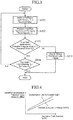
- transmission line abnormality detection by the excitation light source device 1 configured in the above-described manner and the stop/reduction operation of the excitation light source 11 will be described with reference to FIG. 3 .
- the excitation light source device 1 performs a process depicted in FIG. 3 at all times.
- the transmission line abnormality analyzer 16 has information about the type of optical fiber used as the transmission line by means of management communication performed beforehand, etc.
- the light source controller 12 increases the intensity X of excitation light generated by the excitation light source 11 to a specified value (step ST31).
- the light source controller 12 gives information indicating the controlled intensity X of excitation light to the transmission line abnormality analyzer 16.
- the amplified spontaneous emission noise measurer 15 measures the intensity Y of amplified spontaneous emission noise which is caused by the excitation light generated by the excitation light source 11 (step ST32).
- the amplified spontaneous emission noise measurer 15 gives information indicating the measured intensity Y of amplified spontaneous emission noise to the transmission line abnormality analyzer 16.
- the transmission line abnormality analyzer 16 determines, by referring to the reference table 161, whether a threshold value Y ij , which is set for the type of optical fiber in use and the intensity X of excitation light controlled by the light source controller 12, is exceeded by the intensity Y of amplified spontaneous emission noise measured at that time by the amplified spontaneous emission noise measurer 15 (step ST33).
- the transmission line abnormality analyzer 16 judges that there is no abnormality in the transmission line. In this case, the transmission line abnormality analyzer 16 determines, by referring to the reference table 161, whether the intensity X of excitation light controlled by the light source controller 12 exceeds a set value X n (step ST34). When the transmission line abnormality analyzer 16 judges at this step ST34 that the intensity X of excitation light exceeds the set value X n , the sequence is ended.
- step ST34 when the transmission line abnormality analyzer 16 judges at step ST34 that the intensity X of excitation light does not exceed the set value X n , the sequence returns to step ST31. Thereafter, processes at steps ST31 to ST33 are repeated.
- the transmission line abnormality analyzer 16 judges at step ST33 that the threshold value Y ij is not exceeded by the intensity Y of amplified spontaneous emission noise, the transmission line abnormality analyzer 16 judges that there is abnormality in the transmission line.
- the light source controller 12 stops or reduces the generation of excitation light by the excitation light source 11 (step ST35). Thereafter, an operator cleans up the transmission line, and after contamination of the transmission line is removed, operation of optical communication is resumed.
- the transmission line abnormality analyzer 16 detects abnormality in the transmission line, the transmission line abnormality analyzer 16 generates, for example, an alarm to notify all network devices of the optical transmission system or a network administrator of the occurrence of abnormality in the transmission line.
- the reference table 161 shown in FIG. 2 shows a case in which threshold values are set for each fiber type.
- the configuration is not limited thereto, and for example, losses caused by optical connector connections may be taken into account in computation of threshold values and the threshold values may be set for each number of optical connector connections.
- the transmission line abnormality analyzer 16 has information about the number of optical connector connections in the transmission line by means of management communication performed beforehand, etc.
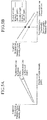
- the intensity of amplified spontaneous emission noise caused by Raman amplification is specified by the intensity of excitation light and a cross section of an optical fiber.
- FIG. 5A when there is a loss in the transmission line due to contamination of an end surface of an optical connector, etc. (i.e., when the transmission line is in abnormal), the intensity of excitation light in the transmission line decreases, and accordingly, the intensity of amplified spontaneous emission noise also decreases.
- FIG. 5B when the intensity of excitation light and the type of optical fiber are input as pre-information, the intensity of amplified spontaneous emission noise depends on a loss caused by abnormality in the transmission line.
- abnormality in the transmission line is detected by focusing attention on the phenomenon discussed above. For example, when there is a loss in the transmission line due to contamination of an optical connector, the intensity of amplified spontaneous emission noise decreases depending on the magnitude of the loss. That is, when the intensity of excitation light and the type of optical fiber are input as pre-information, abnormality in the transmission line can be detected by measuring the intensity of amplified spontaneous emission noise.
- the amplification principle of an optical Raman amplifier involved in the present invention uses stimulated Raman scattering which is a nonlinear optical effect of an optical fiber. Specifically, a phenomenon is used where, when the total power of an optical signal passing through the transmission line exceeds a specific threshold value, stimulated Raman scattering light (i.e., amplified spontaneous emission noise) is generated on the long-wavelength side of the order of 100 nm from the optical signal.
- stimulated Raman scattering light i.e., amplified spontaneous emission noise
- the Embodiment 1 it is configured such that the intensity of excitation light generated by the excitation light source 11 is gradually increased from a low value at which transmission line abnormality does not occur, and it is determined, based on the intensity of amplified spontaneous emission noise generated at that time, whether there is abnormality in a transmission line, and if abnormality is detected, the generation of excitation light by the excitation light source 11 is stopped or reduced. Therefore, without an additional device, an abnormal state of the transmission line can be detected before the occurrence of damage to the transmission line. Furthermore, when abnormality in the transmission line is detected, the intensity of excitation light can be reduced.
- a light source for transmission line abnormality detection can be eliminated from the excitation light source device 1.
- miniaturization and cost reduction of the excitation light source device 1 can be achieved.
- transmission line abnormality can be detected by the excitation light source device 1 alone, the content of control and content of adjustment required can be simplified over the conventional configurations.
- the amplified spontaneous emission noise measurer 15 of the excitation light source device 1 disposed on the upstream side of the transmission line measures a loss of amplified spontaneous emission noise that propagates in the same direction (i.e., a forward direction) as that of main signal light.
- FIG. 6 is a diagram representing a configuration of an excitation light source device 1b according to the Embodiment 2 of the invention.
- the excitation light source device 1b according to the Embodiment 2 shown in FIG. 6 is configured such that, an amplified spontaneous emission noise measurer 15 of an excitation light source device 1 according to the Embodiment 1 shown in FIG. 1 is removed, and a Raman gain measurer 19 is introduced. Furthermore, a light source controller 12 and a transmission line abnormality analyzer 16 are changed to a light source controller 12b and a transmission line abnormality analyzer 16b. Other configurations are the same and thus are denoted by the same reference signs, and description thereof is omitted.
- the light source controller 12b is to control the intensity of excitation light generated by an excitation light source 11 on a basis of a result of analysis by the transmission line abnormality analyzer 16b. In a state where abnormality is not detected by the transmission line abnormality analyzer 16b, the light source controller 12b gradually increases the intensity of excitation light generated by the excitation light source 11 to a set value. When the abnormality is detected by the transmission line abnormality analyzer 16b, the light source controller 12b stops or reduces the generation of excitation light by the excitation light source 11.
- the light source controller 12b can be implemented by using, for example, a microcomputer or an FPGA (Field Programmable Gate Array).
- the Raman gain measurer 19 is to measure Raman gain that is given to signal light and is caused by the excitation light generated by the excitation light source 11.
- the Raman gain measurer 19 measures Raman gain that is given to main signal light and is generated by means of a Raman amplification effect occurring in a transmission line due to the excitation light from the excitation light source 11. Note that the Raman gain is not a general gain that is represented by a ratio of input optical power to output optical power, but is represented by a ratio of output optical power obtained upon non-excitation to output optical power obtained upon excitation.
- the transmission line abnormality analyzer 16b is to detect abnormality in the transmission line on a basis of the control state (the state of supply of excitation light) of the light source controller 12b and a measurement result of the Raman gain measurer 19.
- the transmission line abnormality analyzer 16b has a reference table 161b for detecting abnormality in the transmission line. As shown in FIG. 7 , the reference table 161b is a storage area that stores gradual values [mW] up to a set value of the intensity of excitation light, and threshold values [dB] for Raman gain for each type of optical fiber. Note that it is assumed that the transmission line abnormality analyzer 16b has information about the type of optical fiber used as the transmission line by means of management communication performed beforehand, etc.
- the transmission line abnormality analyzer 16b determines, by referring to the rows and columns of the reference table 161b, that a threshold value set for the type of optical fiber in use and the intensity of excitation light controlled by the light source controller 12b is not exceeded by the intensity of Raman gain measured at that time by the Raman gain measurer 19, the transmission line abnormality analyzer 16b judges that the transmission line is in abnormal.
- the reference table 161b is not limited to the one shown in FIG. 7 , and may be any as long as the table functions as a reference table, and thus various types of reference tables can be used.
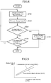
- transmission line abnormality detection by the excitation light source device 1b configured in the above-described manner and the stop/reduction operation of the excitation light source 11 will be described with reference to FIG. 8 .
- the excitation light source device 1b performs processes shown in FIG. 8 at all times.
- the transmission line abnormality analyzer 16b has information about the type of optical fiber used as the transmission line by means of management communication performed beforehand, etc.
- the light source controller 12b increases the intensity X of excitation light generated by the excitation light source 11 to a specified value (step ST81).
- the light source controller 12b gives information indicating the controlled intensity X of excitation light to the transmission line abnormality analyzer 16b.
- the Raman gain measurer 19 measures Raman gain Z that is given to signal light caused by the excitation light generated by the excitation light source 11 (step ST82).
- the Raman gain measurer 19 gives information indicating the measured Raman gain Z to the transmission line abnormality analyzer 16b.
- the transmission line abnormality analyzer 16b determines, by referring to the reference table 161b, whether a threshold value Z ij , which is set for the type of optical fiber in use and the intensity X of excitation light controlled by the light source controller 12b, is exceeded by the Raman gain Z measured at that time by the Raman gain measurer 19 (step ST83).
- the transmission line abnormality analyzer 16b judges that there is no abnormality in the transmission line. In this case, the transmission line abnormality analyzer 16b determines, by referring to the reference table 161b, whether the intensity X of excitation light controlled by the light source controller 12b exceeds a set value X n (step ST84). When the transmission line abnormality analyzer 16b judges at this step ST84 that the intensity X of excitation light exceeds the set value X n , the sequence is ended.
- step ST84 when the transmission line abnormality analyzer 16b judges at step ST84 that the intensity X of excitation light does not exceed the set value X n , the sequence returns to step ST81. Thereafter, processes at steps ST81 to ST83 are repeated.
- the transmission line abnormality analyzer 16b judges at step ST83 that the threshold value Z ij is not exceeded by the Raman gain Z, the transmission line abnormality analyzer 16b judges that there is abnormality in the transmission line.
- the light source controller 12b stops or reduces the generation of excitation light by the excitation light source 11 (step ST85). Thereafter, an operator cleans up the transmission line, and after contamination of the transmission line is removed, operation of optical communication is resumed.
- the transmission line abnormality analyzer 16b detects abnormality in the transmission line, the transmission line abnormality analyzer 16b generates, for example, an alarm to notify all network devices of an optical transmission system or a network administrator of the occurrence of abnormality in the transmission line.
- the reference table 161b shown in FIG. 7 shows a case in which threshold values are set for each type of optical fiber.
- the configuration is not limited thereto, and for example, losses caused by optical connector connections may be taken into account in computation of threshold values and the threshold values may be set for each number of optical connector connections.
- the transmission line abnormality analyzer 16b has information about the number of optical connector connections in the transmission line by means of management communication performed beforehand, etc.
- Raman gain generated by Raman amplification is determined by the intensity of excitation light and the cross section of an optical fiber.
- FIG. 10A when there is a loss in the transmission line due to contamination of an optical connector end surface, etc. (i.e., when the transmission line is in abnormal), the intensity of excitation light in the transmission line decreases, and accordingly, the Raman gain also decreases.
- FIG. 10B when the intensity of excitation light and the type of optical fiber are input as pre-information, the Raman gain depends on a loss caused by abnormality in the transmission line.
- abnormality in the transmission line is detected by focusing attention on the phenomenon discussed above. For example, when there is a loss in the transmission line due to contamination of an optical connector, the Raman gain decreases according to the magnitude of the loss. That is, when the intensity of excitation light and the type of optical fiber are input as pre-information, abnormality in the transmission line can be detected by measuring Raman gain.
- the Raman gain measurer 19 may measure Raman gain that is given to light for monitoring and control, instead of the main signal light.
- Embodiment 2 even when it is configured such that abnormality in a transmission line is detected based on the state of supply of excitation light and Raman gain which is given to signal light caused by the excitation light, the same effects as those of the Embodiment 1 can be obtained.
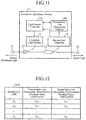
- FIG. 11 is a configuration diagram representing an excitation light source device 1c according to the Embodiment 3 of the invention.
- the excitation light source device 1c according to the Embodiment 3 shown in FIG. 11 is such that a light source controller 12b and a transmission line abnormality analyzer 16b of an excitation light source device 1b according to the Embodiment 2 shown in FIG. 6 are changed to a light source controller 12c and a transmission line abnormality analyzer 16c.
- Other configurations are the same and thus are denoted by the same reference signs and description thereof is omitted.
- the light source controller 12c is to control the intensity of excitation light generated by an excitation light source 11 on a basis of a result of measurement by a Raman gain measurer 19 and a result of analysis by the transmission line abnormality analyzer 16c. In a state where abnormality is not detected by the transmission line abnormality analyzer 16c, the light source controller 12c gradually increases the intensity of excitation light generated by the excitation light source 11 so as to gradually increase Raman gain measured by the Raman gain measurer 19 to a target value. When the abnormality is detected by the transmission line abnormality analyzer 16c, the light source controller 12c stops or reduces the generation of excitation light by the excitation light source 11.
- the light source controller 12c can be implemented by using, for example, a microcomputer or an FPGA (Field Programmable Gate Array).
- the transmission line abnormality analyzer 16c is to detect abnormality in a transmission line on a basis of the control state (the state of supply of excitation light) by the light source controller 12c and a result of measurement by the Raman gain measurer 19.
- the transmission line abnormality analyzer 16c has a reference table 161c for detecting abnormality in the transmission line. As shown in FIG. 12 , the reference table 161c is a storage area that stores gradual values [dB] up to a set value of Raman gain, and threshold values [mW] for the intensity of excitation light for each type of optical fiber. Note that it is assumed that the transmission line abnormality analyzer 16c has information about the type of optical fiber used as the transmission line by means of management communication performed beforehand, etc.
- the transmission line abnormality analyzer 16c determines, by referring to the rows and columns of the reference table 161c, that a threshold value set for the type of optical fiber in use and Raman gain measured by the Raman gain measurer 19 is not exceeded by the intensity of excitation light controlled at that time by the light source controller 12c, the transmission line abnormality analyzer 16c judges that the transmission line is in abnormal.
- the reference table 161c is not limited to the one shown in FIG. 12 , and may be any as long as the table functions as a reference table, and thus various types of reference tables can be used.
- an automatic gain control (AGC) system for a system for controlling a drive current of the excitation light source 11 by the light source controller 12c, it is preferred to use an automatic gain control (AGC) system.
- AGC automatic gain control
- the simplest control mode for the case of the auto gain control is a method for changing the intensity of output from the excitation light source 11 such that the Raman gain monitored by the Raman gain measurer 19 follows a target value.
- transmission line abnormality detection by the excitation light source device 1c configured in the above-described manner and the stop/reduction operation of the excitation light source 11 will be described with reference to FIG. 13 .
- the excitation light source device 1c performs processes shown in FIG. 13 at all times.
- the transmission line abnormality analyzer 16c has information about the type of optical fiber used as the transmission line by means of management communication performed beforehand, etc.
- the light source controller 12c increases the intensity X of excitation light generated by the excitation light source 11, such that Raman gain Z follows a target value Z; by increasing the Raman gain Z to a specified value according to the auto gain control system (step ST131).
- the light source controller 12c measures the controlled intensity X of excitation light (step ST132). Then, the light source controller 12c gives information indicating the controlled intensity X of excitation light to the transmission line abnormality analyzer 16c.
- the Raman gain measurer 19 measures Raman gain Z that is given to signal light caused by the excitation light generated by the excitation light source 11 (step ST133).
- the Raman gain measurer 19 gives information indicating the measured Raman gain Z to the transmission line abnormality analyzer 16c.
- the transmission line abnormality analyzer 16c determines, by referring to the reference table 161c, whether a threshold value X ij set for the type of optical fiber in use and the Raman gain Z measured by the Raman gain measurer 19 is exceeded by the intensity X of excitation light controlled at that time by the light source controller 12c (step ST134).
- the transmission line abnormality analyzer 16c judges at this step ST134 that the threshold value X ij is exceeded by the intensity X of excitation light, the transmission line abnormality analyzer 16c determines, by referring to the reference table 161c, whether the Raman gain Z measured by the Raman gain measurer 19 has reached the target value Z i set at step ST131 (step ST135).
- the transmission line abnormality analyzer 16c judges at this step ST135 that the Raman gain Z has reached the target value Z i set at step ST131, the transmission line abnormality analyzer 16c determines, by referring to the reference table 161c, whether the Raman gain Z measured by the Raman gain measurer 19 exceeds a target value (value for normal operation) Z n (step ST136).
- the transmission line abnormality analyzer 16c judges at this step ST136 that the Raman gain Z exceeds the target value Z n , the sequence is ended.
- step ST136 when the transmission line abnormality analyzer 16c judges at step ST136 that the Raman gain Z does not exceed the target value Z n , the sequence returns to step ST131.
- the transmission line abnormality analyzer 16c judges that there is abnormality in the transmission line.
- the light source controller 12c stops or reduces the generation of excitation light by the excitation light source 11 (step ST137). Thereafter, an operator cleans up the transmission line, and when contamination of the transmission line is removed, operation of optical communication is resumed.
- the transmission line abnormality analyzer 16c detects abnormality in the transmission line, the transmission line abnormality analyzer 16c generates, for example, an alarm to notify all network devices of an optical transmission system or a network administrator of the occurrence of abnormality in the transmission line.
- Embodiment 3 even when it is configured such that the intensity of excitation light is controlled such that Raman gain follows a target value, and abnormality in a transmission line is detected based on the intensity of excitation light controlled at that time, the same effects as those of the Embodiment 2 can be obtained.
- the Excitation light source devices and the optical transmission systems according to the present invention can detect an abnormal state of a transmission line before the occurrence of damage to the transmission line without an additional device, and can reduce the output level of Raman excitation light when abnormality in the transmission line is detected.
- the excitation light source devices and the optical transmission systems are suitable for use as, for example, excitation light source devices that output Raman excitation light that amplifies signal light to a transmission line on which the signal light is transmitted, and optical transmission systems including the excitation light source devices.
Landscapes
- Physics & Mathematics (AREA)
- Electromagnetism (AREA)
- Engineering & Computer Science (AREA)
- Computer Networks & Wireless Communication (AREA)
- Signal Processing (AREA)
- Optical Modulation, Optical Deflection, Nonlinear Optics, Optical Demodulation, Optical Logic Elements (AREA)
- Optical Communication System (AREA)
Claims (18)
- Erregungslichtquellen-Vorrichtung, die dazu ausgelegt ist, ein Raman-Erregungslicht-Verstärkungslichtsignal an eine Übertragungsleitung zu senden, auf der das Lichtsignal übertragen wird, wobei die Erregungslichtquellen-Vorrichtung Folgendes aufweist:- eine Erregungslichtquellen-Vorrichtung (11), um das Raman-Erregungslicht zu erzeugen;- eine Lichtquellen-Steuereinheit (12), um die Intensität des von der Erregungslichtquelle (11) erzeugten Raman-Erregungslichts zu steuern;- eine Messeinrichtung (15) für verstärktes Spontanemissionsrauschen, um die Intensität von verstärktem Spontanemissionsrauschen zu messen, das durch ein von der Erregungslichtquelle (11) erzeugtes Raman-Erregungslicht verursacht wird; und- einen Übertragungsleitungs-Anormalitätsanalysator (16), um eine Anormalität in der Übertragungsleitung basierend auf dem Steuerungszustand der Lichtquellensteuerungseinheit (12) und dem Messergebnis der Messeinrichtung (15) des verstärkten Spontanemissionsrauschens zu erfassen, wobei in einem Zustand, in dem von dem Übertragungsleitungs-Anormalitätsanalysator (16) die Anormalität erfasst wird, die Lichtquellen-Steuereinheit (12) dazu ausgelegt ist, die Erregungslichtquelle (11) zu steuern, um die Erzeugung von Raman-Erregungslicht zu beenden oder zu verringern,dadurch gekennzeichnet,
dass in einem Zustand, in dem die Anormalität von dem Übertragungsleitungs-Anormalitätsanalysator (16) nicht erfasst wird, die Lichtquellen-Steuereinheit (12) dazu ausgelegt ist, die Intensität des durch die Erregungslichtquelle (11) erzeugten Raman-Erregungslichts so zu steuern, dass es allmählich auf einen vorgegebenen Wert ansteigt. - Erregungslichtquellen-Vorrichtung nach Anspruch 1,
wobei dann, wenn ein Grenzwert, der für eine Intensität des Raman-Erregungslichts, die von der Lichtquellen-Steuereinheit (12) gesteuert wird, vorgegeben ist, nicht von der Intensität des verstärkten Spontanemissionsrauschens überschritten wird, das zu diesem Zeitpunkt von der Messeinrichtung (15) für verstärktes Spontanemissionsrauschens gemessen wird, der Übertragungsleitungs-Anormalitätsanalysator (16) dazu ausgelegt ist, zu beurteilen, dass sich die Übertragungsleitung in einem anormalen Zustand befindet. - Erregungslichtquellen-Vorrichtung nach Anspruch 2,
wobei der Grenzwert für den jeweiligen Typ der die Übertragungsleitung bildenden Lichtwellenleiter vorgegeben ist. - Erregungslichtquellen-Vorrichtung nach Anspruch 2,
wobei der Grenzwert für die jeweilige Anzahl von angeschlossenen optischen Verbindern in der Übertragungsleitung vorgegeben ist. - Erregungslichtquellen-Vorrichtung, die dazu ausgelegt ist, ein Raman-Erregungslicht-Verstärkungslichtsignal an eine Übertragungsleitung zu senden, auf der das Lichtsignal übertragen wird, wobei die Erregungslichtquellen-Vorrichtung Folgendes aufweist:- eine Erregungslichtquellen-Vorrichtung (11), um das Raman-Erregungslicht zu erzeugen;- eine Lichtquellen-Steuereinheit (12), um die Intensität des von der Erregungslichtquelle (11) erzeugten Raman-Erregungslichts zu steuern;- eine Raman-Verstärkungs-Messeinrichtung (19), um die Raman-Verstärkung zu messen, die das Lichtsignal erhalten hat und die von dem von der Erregungslichtquelle (11) erzeugten Raman-Erregungslicht verursacht wird; und- einen Übertragungsleitungs-Anormalitätsanalysator (16), um eine Anormalität in der Übertragungsleitung basierend auf dem Steuerzustand der Lichtquellen-Steuereinheit (12) und dem Messergebnis der Raman-Verstärkungs-Messeinrichtung (19) zu erfassen,wobei in einem Zustand, in dem die Anormalität von dem Übertragungsleitungs-Anormalitätsanalysator (16) erfasst wird, die Lichtquellen-Steuereinheit (12) dazu ausgelegt ist, die Erregungslichtquelle (11) zu steuern, um die Erzeugung von Raman-Erregungslicht zu beenden oder zu verringern,
dadurch gekennzeichnet,
dass in einem Zustand, in dem die Anormalität von dem Übertragungsleitungs-Anormalitätsanalysator (16) nicht erfasst wird, die Lichtquellen-Steuereinheit (12) dazu ausgelegt ist, die Intensität des von der Erregungslichtquelle (11) erzeugten Raman-Erregungslichts so zu steuern, dass es allmählich auf einen vorgegebenen Wert ansteigt. - Erregungslichtquellen-Vorrichtung nach Anspruch 5,
wobei dann, wenn ein Grenzwert, der für eine Intensität des Raman-Erregungslichts (12) vorgegeben ist, die von der Lichtquellen-Steuereinheit (12) gesteuert wird, nicht von der Raman-Verstärkung überschritten wird, die zu diesem Zeitpunkt von der Raman-Verstärkungs-Messeinrichtung (19) gemessen wird, der Übertragungsleitungs-Anormalitätsanalysator (16) dazu ausgelegt ist, zu beurteilen, dass sich die Übertragungsleitung in einem anormalen Zustand befindet. - Erregungslichtquellen-Vorrichtung nach Anspruch 6,
wobei der Grenzwert für den jeweiligen Typ der die Übertragungsleitung bildenden Lichtwellenleiter vorgegeben ist. - Erregungslichtquellen-Vorrichtung nach Anspruch 6,
wobei der Grenzwert für die jeweilige Anzahl von angeschlossenen optischen Verbindern in der Übertragungsleitung vorgegeben ist. - Erregungslichtquellen-Vorrichtung, die dazu ausgelegt ist, ein Raman-Erregungslicht-Verstärkungslichtsignal an eine Übertragungsleitung zu senden, auf der das Lichtsignal übertragen wird, wobei die Erregungslichtquellen-Vorrichtung Folgendes aufweist:- eine Erregungslichtquellen-Vorrichtung (11), um das Raman-Erregungslicht zu erzeugen;- eine Raman-Verstärkungs-Messeinrichtung (19), um die Raman-Verstärkung zu messen, die das Lichtsignal erhalten hat und die von dem von der Erregungslichtquelle (11) erzeugten Raman-Erregungslicht verursacht wird;- eine Lichtquellen-Steuereinheit (12), um basierend auf dem Messergebnis der Raman-Verstärkungs-Messeinrichtung (19) die Intensität des von der Erregungslichtquelle (111) erzeugten Raman-Erregungslichts zu steuern; und- einen Übertragungsleitungs-Anormalitätsanalysator (16), um basierend auf dem Steuerungszustand der Lichtquellen-Steuereinheit (12) und dem Messergebnis der Raman-Verstärkungs-Messeinrichtung (19) eine Anormalität in der Übertragungsleitung zu erfassen,wobei in einem Zustand, in dem die Anormalität von dem Übertragungsleitungs-Anormalitätsanalysator (16) nicht erfasst wird, die Lichtquellen-Steuereinheit (12) dazu ausgelegt ist, die Erhöhung der Intensität des durch die Erregungslichtquelle (11) erzeugten Raman-Erregungslichts so zu steuern, dass die Raman-Verstärkung allmählich auf einen vorgegebenen Wert ansteigt, und
dadurch gekennzeichnet,
dass in einem Zustand, in dem die Anormalität von dem Übertragungsleitungs-Anormalitätsanalysator (16) erfasst wird, die Lichtquellen-Steuereinheit (11) dazu ausgebildet ist, die Erregungslichtquelle (12) zu steuern, um die Erzeugung von Raman-Erregungslicht zu beenden oder zu verringern, - Erregungslichtquellen-Vorrichtung nach Anspruch 9,
wobei die Lichtquellen-Steuereinheit (12) dazu ausgelegt ist, die Erregungslichtquelle (11) mit einem automatischen Verstärkungssteuerungssystem basierend auf der von der Raman-Verstärkungs-Messeinrichtung (19) gemessenen Raman-Verstärkung zu steuern. - Erregungslichtquellen-Vorrichtung nach Anspruch 9,
wobei dann, wenn ein Grenzwert, der für die Raman-Verstärkung vorgegeben ist, die von der Raman-Verstärkungs-Messeinrichtung (19) gemessen wird, nicht von der Intensität des Raman-Erregungslichts überschritten wird, die zu diesem Zeitpunkt von der Lichtquellen-Steuereinheit (12) gesteuert wird, der Übertragungsleitungs-Anormalitätsanalysator (16) dazu ausgelegt ist, zu beurteilen, dass sich die Übertragungsleitung in einem anormalen Zustand befindet. - Erregungslichtquellen-Vorrichtung nach Anspruch 11,
wobei der Grenzwert für den jeweiligen Typ von die Übertragungsleitung bildenden Lichtwellenleitern vorgegeben ist. - Erregungslichtquellen-Vorrichtung nach Anspruch 11,
wobei der Grenzwert für die jeweilige Anzahl von angeschlossenen optischen Verbindern in der Übertragungsleitung vorgegeben ist. - Optisches Übertragungssystem, das Folgendes aufweist:- eine Übertragungsleitung, auf der Lichtsignal übertragen wird; und- eine Erregungslichtquellen-Vorrichtung nach Anspruch 1, die an einer vorgelagerten Seite der Übertragungsleitung angeordnet ist.
- Optisches Übertragungssystem, das Folgendes aufweist:- eine Übertragungsleitung, auf der Lichtsignal übertragen wird; und- eine Erregungslichtquellen-Vorrichtung nach Anspruch 1, die an einer nachgelagerten Seite der Übertragungsleitung angeordnet ist.
- Optisches Übertragungssystem, das Folgendes aufweist:- eine Übertragungsleitung, auf der Lichtsignal übertragen wird; und- eine Erregungslichtquellen-Vorrichtung nach Anspruch 1, die an einer jeden von einer vorgelagerten Seite und einer nachgelagerten Seite der Übertragungsleitung angeordnet ist.
- Optisches Übertragungssystem, das Folgendes aufweist:- eine Übertragungsleitung, auf der Lichtsignal übertragen wird; und- eine Erregungslichtquellen-Vorrichtung nach Anspruch 5, die an einer nachgelagerten Seite der Übertragungsleitung angeordnet ist.
- Optisches Übertragungssystem, das Folgendes aufweist:- eine Übertragungsleitung, auf der Lichtsignal übertragen wird; und- eine Erregungslichtquellen-Vorrichtung nach Anspruch 9, die an einer nachgelagerten Seite der Übertragungsleitung angeordnet ist.
Applications Claiming Priority (1)
| Application Number | Priority Date | Filing Date | Title |
|---|---|---|---|
| PCT/JP2014/050697 WO2015107658A1 (ja) | 2014-01-16 | 2014-01-16 | 励起光源装置及び光伝送システム |
Publications (3)
| Publication Number | Publication Date |
|---|---|
| EP3096181A1 EP3096181A1 (de) | 2016-11-23 |
| EP3096181A4 EP3096181A4 (de) | 2017-08-30 |
| EP3096181B1 true EP3096181B1 (de) | 2018-12-05 |
Family
ID=53542577
Family Applications (1)
| Application Number | Title | Priority Date | Filing Date |
|---|---|---|---|
| EP14878715.3A Active EP3096181B1 (de) | 2014-01-16 | 2014-01-16 | Erregungslichtquellenvorrichtung und optisches übertragungssystem |
Country Status (5)
| Country | Link |
|---|---|
| US (1) | US9831953B2 (de) |
| EP (1) | EP3096181B1 (de) |
| JP (1) | JP6324415B2 (de) |
| CN (1) | CN106415384B (de) |
| WO (1) | WO2015107658A1 (de) |
Families Citing this family (2)
| Publication number | Priority date | Publication date | Assignee | Title |
|---|---|---|---|---|
| JP6908511B2 (ja) * | 2017-12-07 | 2021-07-28 | 三菱パワー株式会社 | ラマン散乱光取得装置、これを備える組成分析装置、及びガスタービンプラント |
| US12199664B2 (en) * | 2020-05-28 | 2025-01-14 | Nippon Telegraph And Telephone Corporation | Light leakage confirmation method, light leakage confirmation apparatus and program |
Family Cites Families (24)
| Publication number | Priority date | Publication date | Assignee | Title |
|---|---|---|---|---|
| JP4671478B2 (ja) * | 2000-08-08 | 2011-04-20 | 富士通株式会社 | 波長多重光通信システムおよび波長多重光通信方法 |
| JP4509451B2 (ja) * | 2000-09-07 | 2010-07-21 | 富士通株式会社 | ラマン増幅を利用した光増幅装置 |
| JP3904835B2 (ja) * | 2001-01-29 | 2007-04-11 | 株式会社日立製作所 | 光増幅器、光ファイバラマン光増幅器、及び光システム |
| JP3587176B2 (ja) * | 2001-04-02 | 2004-11-10 | 日本電気株式会社 | ラマン増幅器及びラマン増幅方法 |
| US6807001B1 (en) * | 2001-04-17 | 2004-10-19 | Sycamore Networks, Inc. | Auto shutdown for distributed raman amplifiers on optical communication systems |
| US6660990B2 (en) * | 2001-06-01 | 2003-12-09 | Nortel Networks Limited | Optical amplification and receiving system and method |
| JP3992565B2 (ja) * | 2002-08-27 | 2007-10-17 | 富士通株式会社 | 光伝送システム |
| JP4101024B2 (ja) * | 2002-11-06 | 2008-06-11 | 富士通株式会社 | ロスポイント有無判定方法及びそれを用いた分布型ラマン増幅装置 |
| JP4046602B2 (ja) * | 2002-12-06 | 2008-02-13 | 三菱電機株式会社 | ラマン増幅器および光中継伝送システム |
| EP1560305B1 (de) * | 2003-03-13 | 2012-07-18 | Fujitsu Limited | Optischer Verstärker mit Kontrollfunktionen des Pumplichts, und optisches Übertragungssystem, das diesen Verstärker verwendet |
| JP4318938B2 (ja) | 2003-03-13 | 2009-08-26 | 富士通株式会社 | 接続損失検出機能を備えた光増幅器 |
| JP4478489B2 (ja) * | 2003-08-01 | 2010-06-09 | 富士通株式会社 | ラマン光増幅器およびラマン光増幅器の調整方法 |
| JP4093937B2 (ja) * | 2003-08-21 | 2008-06-04 | 富士通株式会社 | 光伝送システム |
| EP1522840A1 (de) * | 2003-11-13 | 2005-04-13 | Alcatel | Verfahren und Vorrichtung zur bestimmung von den Verstärkungseigenschaften eines verteilten Ramanverstärkers |
| JP4101202B2 (ja) * | 2004-04-05 | 2008-06-18 | 古河電気工業株式会社 | ラマン増幅器 |
| JP4298570B2 (ja) * | 2004-04-13 | 2009-07-22 | 富士通株式会社 | 光ファイバ増幅器の制御方法および光伝送システム |
| US7116471B2 (en) * | 2004-12-02 | 2006-10-03 | Redc Optical Networking Ltd. | Method and system for improved eye protection safety of distributed Raman amplifiers |
| US7916384B2 (en) * | 2006-05-02 | 2011-03-29 | At&T Intellectual Property Ii, L.P. | Feedback dynamic gain control for a WDM system employing multi wavelength pumped Raman fiber amplifiers |
| JP5277528B2 (ja) * | 2006-10-11 | 2013-08-28 | 日本電気株式会社 | 監視システム、光伝送装置、光伝送システム及び監視レベル設定方法 |
| JP4601676B2 (ja) * | 2008-01-25 | 2010-12-22 | 富士通株式会社 | 分布ラマン増幅を用いた波長多重光通信システム |
| JP2011059424A (ja) * | 2009-09-10 | 2011-03-24 | Fujitsu Ltd | 光伝送装置、光伝送システムおよび光伝送方法 |
| US8576481B2 (en) * | 2010-08-03 | 2013-11-05 | Finisar Israel Ltd. | Method and apparatus of detecting an opening in an optical transmission fiber of a ROPA system |
| JP5595307B2 (ja) * | 2011-03-03 | 2014-09-24 | 株式会社日立製作所 | 光通信用モジュール及び光ファイバ通信システム |
| JP6330500B2 (ja) * | 2014-06-12 | 2018-05-30 | 富士通株式会社 | 増幅装置、受信装置、及び増幅方法 |
-
2014
- 2014-01-16 EP EP14878715.3A patent/EP3096181B1/de active Active
- 2014-01-16 US US15/026,466 patent/US9831953B2/en active Active
- 2014-01-16 CN CN201480073367.4A patent/CN106415384B/zh not_active Expired - Fee Related
- 2014-01-16 JP JP2015557640A patent/JP6324415B2/ja active Active
- 2014-01-16 WO PCT/JP2014/050697 patent/WO2015107658A1/ja not_active Ceased
Non-Patent Citations (1)
| Title |
|---|
| None * |
Also Published As
| Publication number | Publication date |
|---|---|
| CN106415384B (zh) | 2019-06-07 |
| US9831953B2 (en) | 2017-11-28 |
| EP3096181A4 (de) | 2017-08-30 |
| CN106415384A (zh) | 2017-02-15 |
| JPWO2015107658A1 (ja) | 2017-03-23 |
| JP6324415B2 (ja) | 2018-05-16 |
| US20160218809A1 (en) | 2016-07-28 |
| WO2015107658A1 (ja) | 2015-07-23 |
| EP3096181A1 (de) | 2016-11-23 |
Similar Documents
| Publication | Publication Date | Title |
|---|---|---|
| CN107483106B (zh) | 一种在线的光时域反射仪结构、检测系统和检测方法 | |
| US10374704B2 (en) | Raman amplifier system and method with integrated optical time domain reflectometer | |
| EP2701248B1 (de) | Sicherheitssystem für einen Hochleistungsfaserlaser | |
| US6547453B1 (en) | Systems and methods for detecting fault conditions and detecting and preventing potentially dangerous conditions in an optical system | |
| CN102100018B (zh) | 长中继器跨距的高损耗环回 | |
| US20160072576A1 (en) | Live monitoring of raman and fiber degradation in dwdm networks using in-service otdr | |
| US7116471B2 (en) | Method and system for improved eye protection safety of distributed Raman amplifiers | |
| US20050105167A1 (en) | Method of determining the gain characteristic of a distributed Raman amplifier | |
| CN104956607B (zh) | 一种分布式拉曼光放大器的断纤检测方法、装置及系统 | |
| US11658452B2 (en) | Powering up an optical amplifier in an optical line system | |
| EP3096181B1 (de) | Erregungslichtquellenvorrichtung und optisches übertragungssystem | |
| US9264134B2 (en) | Automatic laser shutdown and recovery in response to a link break | |
| JPWO2020022310A1 (ja) | 監視装置および監視方法 | |
| JP2005260700A (ja) | 光ファイバ増幅器とそれに接続された伝送用光ファイバのコネクタ外れ検出方法、光ファイバ増幅器及び光ファイバ増幅器とそれに接続された伝送用光ファイバ | |
| EP1698078B1 (de) | Optisches kommunikationsnetz und komponente dafür | |
| EP3300265B1 (de) | Raman-pumpenanordnung mit verbesserter osc-empfindlichkeit | |
| US12176946B2 (en) | Laser safety shutoff or power reduction for optically amplified fiber optic links with high transmission power | |
| US11824581B2 (en) | Turn-up procedure for local and remote amplifiers in an optical system | |
| US20070103766A1 (en) | Method for monitoring an optical transmission line by means of an optical amplifier and optical amplifier therefor | |
| US20230116474A1 (en) | Single span calibration in a multi-span optical line system | |
| JP2009182030A (ja) | 光増幅器およびシステム、並びに、励起光モニタ方法 | |
| JP2009068877A (ja) | 単一モード光ファイバ伝送路のラマン利得効率分布の評価方法及び評価装置 | |
| CN103843263B (zh) | 光放大链路的嵌入式光时域反射测试 | |
| JP2004172750A (ja) | 光増幅中継伝送システムとその監視制御方法 | |
| JP2004240461A (ja) | 測定装置、光伝送システム、及びラマン利得測定方法 |
Legal Events
| Date | Code | Title | Description |
|---|---|---|---|
| PUAI | Public reference made under article 153(3) epc to a published international application that has entered the european phase |
Free format text: ORIGINAL CODE: 0009012 |
|
| 17P | Request for examination filed |
Effective date: 20160714 |
|
| AK | Designated contracting states |
Kind code of ref document: A1 Designated state(s): AL AT BE BG CH CY CZ DE DK EE ES FI FR GB GR HR HU IE IS IT LI LT LU LV MC MK MT NL NO PL PT RO RS SE SI SK SM TR |
|
| AX | Request for extension of the european patent |
Extension state: BA ME |
|
| DAX | Request for extension of the european patent (deleted) | ||
| A4 | Supplementary search report drawn up and despatched |
Effective date: 20170802 |
|
| RIC1 | Information provided on ipc code assigned before grant |
Ipc: G02F 1/35 20060101AFI20170727BHEP Ipc: H04B 10/071 20130101ALI20170727BHEP Ipc: H04B 10/291 20130101ALI20170727BHEP |
|
| INTG | Intention to grant announced |
Effective date: 20180611 |
|
| RAP1 | Party data changed (applicant data changed or rights of an application transferred) |
Owner name: MITSUBISHI ELECTRIC CORPORATION |
|
| RIN1 | Information on inventor provided before grant (corrected) |
Inventor name: IMANISHI, KATSUNORI Inventor name: TOKURA, TOSHIYUKI Inventor name: SUEOKA, HIDEKI Inventor name: TAKATA, KENGO |
|
| GRAP | Despatch of communication of intention to grant a patent |
Free format text: ORIGINAL CODE: EPIDOSNIGR1 |
|
| STAA | Information on the status of an ep patent application or granted ep patent |
Free format text: STATUS: GRANT OF PATENT IS INTENDED |
|
| GRAS | Grant fee paid |
Free format text: ORIGINAL CODE: EPIDOSNIGR3 |
|
| GRAA | (expected) grant |
Free format text: ORIGINAL CODE: 0009210 |
|
| GRAA | (expected) grant |
Free format text: ORIGINAL CODE: 0009210 |
|
| STAA | Information on the status of an ep patent application or granted ep patent |
Free format text: STATUS: THE PATENT HAS BEEN GRANTED |
|
| AK | Designated contracting states |
Kind code of ref document: B1 Designated state(s): AL AT BE BG CH CY CZ DE DK EE ES FI FR GB GR HR HU IE IS IT LI LT LU LV MC MK MT NL NO PL PT RO RS SE SI SK SM TR |
|
| REG | Reference to a national code |
Ref country code: GB Ref legal event code: FG4D |
|
| REG | Reference to a national code |
Ref country code: CH Ref legal event code: EP |
|
| REG | Reference to a national code |
Ref country code: AT Ref legal event code: REF Ref document number: 1073810 Country of ref document: AT Kind code of ref document: T Effective date: 20181215 |
|
| REG | Reference to a national code |
Ref country code: IE Ref legal event code: FG4D |
|
| REG | Reference to a national code |
Ref country code: DE Ref legal event code: R096 Ref document number: 602014037654 Country of ref document: DE |
|
| REG | Reference to a national code |
Ref country code: NL Ref legal event code: MP Effective date: 20181205 |
|
| REG | Reference to a national code |
Ref country code: AT Ref legal event code: MK05 Ref document number: 1073810 Country of ref document: AT Kind code of ref document: T Effective date: 20181205 |
|
| REG | Reference to a national code |
Ref country code: LT Ref legal event code: MG4D |
|
| PG25 | Lapsed in a contracting state [announced via postgrant information from national office to epo] |
Ref country code: NO Free format text: LAPSE BECAUSE OF FAILURE TO SUBMIT A TRANSLATION OF THE DESCRIPTION OR TO PAY THE FEE WITHIN THE PRESCRIBED TIME-LIMIT Effective date: 20190305 Ref country code: ES Free format text: LAPSE BECAUSE OF FAILURE TO SUBMIT A TRANSLATION OF THE DESCRIPTION OR TO PAY THE FEE WITHIN THE PRESCRIBED TIME-LIMIT Effective date: 20181205 Ref country code: LV Free format text: LAPSE BECAUSE OF FAILURE TO SUBMIT A TRANSLATION OF THE DESCRIPTION OR TO PAY THE FEE WITHIN THE PRESCRIBED TIME-LIMIT Effective date: 20181205 Ref country code: FI Free format text: LAPSE BECAUSE OF FAILURE TO SUBMIT A TRANSLATION OF THE DESCRIPTION OR TO PAY THE FEE WITHIN THE PRESCRIBED TIME-LIMIT Effective date: 20181205 Ref country code: BG Free format text: LAPSE BECAUSE OF FAILURE TO SUBMIT A TRANSLATION OF THE DESCRIPTION OR TO PAY THE FEE WITHIN THE PRESCRIBED TIME-LIMIT Effective date: 20190305 Ref country code: AT Free format text: LAPSE BECAUSE OF FAILURE TO SUBMIT A TRANSLATION OF THE DESCRIPTION OR TO PAY THE FEE WITHIN THE PRESCRIBED TIME-LIMIT Effective date: 20181205 Ref country code: LT Free format text: LAPSE BECAUSE OF FAILURE TO SUBMIT A TRANSLATION OF THE DESCRIPTION OR TO PAY THE FEE WITHIN THE PRESCRIBED TIME-LIMIT Effective date: 20181205 Ref country code: HR Free format text: LAPSE BECAUSE OF FAILURE TO SUBMIT A TRANSLATION OF THE DESCRIPTION OR TO PAY THE FEE WITHIN THE PRESCRIBED TIME-LIMIT Effective date: 20181205 |
|
| PG25 | Lapsed in a contracting state [announced via postgrant information from national office to epo] |
Ref country code: AL Free format text: LAPSE BECAUSE OF FAILURE TO SUBMIT A TRANSLATION OF THE DESCRIPTION OR TO PAY THE FEE WITHIN THE PRESCRIBED TIME-LIMIT Effective date: 20181205 Ref country code: SE Free format text: LAPSE BECAUSE OF FAILURE TO SUBMIT A TRANSLATION OF THE DESCRIPTION OR TO PAY THE FEE WITHIN THE PRESCRIBED TIME-LIMIT Effective date: 20181205 Ref country code: RS Free format text: LAPSE BECAUSE OF FAILURE TO SUBMIT A TRANSLATION OF THE DESCRIPTION OR TO PAY THE FEE WITHIN THE PRESCRIBED TIME-LIMIT Effective date: 20181205 Ref country code: GR Free format text: LAPSE BECAUSE OF FAILURE TO SUBMIT A TRANSLATION OF THE DESCRIPTION OR TO PAY THE FEE WITHIN THE PRESCRIBED TIME-LIMIT Effective date: 20190306 |
|
| PG25 | Lapsed in a contracting state [announced via postgrant information from national office to epo] |
Ref country code: NL Free format text: LAPSE BECAUSE OF FAILURE TO SUBMIT A TRANSLATION OF THE DESCRIPTION OR TO PAY THE FEE WITHIN THE PRESCRIBED TIME-LIMIT Effective date: 20181205 |
|
| PG25 | Lapsed in a contracting state [announced via postgrant information from national office to epo] |
Ref country code: IT Free format text: LAPSE BECAUSE OF FAILURE TO SUBMIT A TRANSLATION OF THE DESCRIPTION OR TO PAY THE FEE WITHIN THE PRESCRIBED TIME-LIMIT Effective date: 20181205 Ref country code: CZ Free format text: LAPSE BECAUSE OF FAILURE TO SUBMIT A TRANSLATION OF THE DESCRIPTION OR TO PAY THE FEE WITHIN THE PRESCRIBED TIME-LIMIT Effective date: 20181205 Ref country code: PT Free format text: LAPSE BECAUSE OF FAILURE TO SUBMIT A TRANSLATION OF THE DESCRIPTION OR TO PAY THE FEE WITHIN THE PRESCRIBED TIME-LIMIT Effective date: 20190405 Ref country code: PL Free format text: LAPSE BECAUSE OF FAILURE TO SUBMIT A TRANSLATION OF THE DESCRIPTION OR TO PAY THE FEE WITHIN THE PRESCRIBED TIME-LIMIT Effective date: 20181205 |
|
| PG25 | Lapsed in a contracting state [announced via postgrant information from national office to epo] |
Ref country code: IS Free format text: LAPSE BECAUSE OF FAILURE TO SUBMIT A TRANSLATION OF THE DESCRIPTION OR TO PAY THE FEE WITHIN THE PRESCRIBED TIME-LIMIT Effective date: 20190405 Ref country code: RO Free format text: LAPSE BECAUSE OF FAILURE TO SUBMIT A TRANSLATION OF THE DESCRIPTION OR TO PAY THE FEE WITHIN THE PRESCRIBED TIME-LIMIT Effective date: 20181205 Ref country code: EE Free format text: LAPSE BECAUSE OF FAILURE TO SUBMIT A TRANSLATION OF THE DESCRIPTION OR TO PAY THE FEE WITHIN THE PRESCRIBED TIME-LIMIT Effective date: 20181205 Ref country code: SM Free format text: LAPSE BECAUSE OF FAILURE TO SUBMIT A TRANSLATION OF THE DESCRIPTION OR TO PAY THE FEE WITHIN THE PRESCRIBED TIME-LIMIT Effective date: 20181205 Ref country code: SK Free format text: LAPSE BECAUSE OF FAILURE TO SUBMIT A TRANSLATION OF THE DESCRIPTION OR TO PAY THE FEE WITHIN THE PRESCRIBED TIME-LIMIT Effective date: 20181205 |
|
| REG | Reference to a national code |
Ref country code: CH Ref legal event code: PL |
|
| REG | Reference to a national code |
Ref country code: DE Ref legal event code: R097 Ref document number: 602014037654 Country of ref document: DE |
|
| PG25 | Lapsed in a contracting state [announced via postgrant information from national office to epo] |
Ref country code: LU Free format text: LAPSE BECAUSE OF NON-PAYMENT OF DUE FEES Effective date: 20190116 |
|
| PLBE | No opposition filed within time limit |
Free format text: ORIGINAL CODE: 0009261 |
|
| STAA | Information on the status of an ep patent application or granted ep patent |
Free format text: STATUS: NO OPPOSITION FILED WITHIN TIME LIMIT |
|
| REG | Reference to a national code |
Ref country code: BE Ref legal event code: MM Effective date: 20190131 |
|
| REG | Reference to a national code |
Ref country code: IE Ref legal event code: MM4A |
|
| PG25 | Lapsed in a contracting state [announced via postgrant information from national office to epo] |
Ref country code: DK Free format text: LAPSE BECAUSE OF FAILURE TO SUBMIT A TRANSLATION OF THE DESCRIPTION OR TO PAY THE FEE WITHIN THE PRESCRIBED TIME-LIMIT Effective date: 20181205 Ref country code: SI Free format text: LAPSE BECAUSE OF FAILURE TO SUBMIT A TRANSLATION OF THE DESCRIPTION OR TO PAY THE FEE WITHIN THE PRESCRIBED TIME-LIMIT Effective date: 20181205 Ref country code: MC Free format text: LAPSE BECAUSE OF FAILURE TO SUBMIT A TRANSLATION OF THE DESCRIPTION OR TO PAY THE FEE WITHIN THE PRESCRIBED TIME-LIMIT Effective date: 20181205 |
|
| 26N | No opposition filed |
Effective date: 20190906 |
|
| PG25 | Lapsed in a contracting state [announced via postgrant information from national office to epo] |
Ref country code: BE Free format text: LAPSE BECAUSE OF NON-PAYMENT OF DUE FEES Effective date: 20190131 |
|
| PG25 | Lapsed in a contracting state [announced via postgrant information from national office to epo] |
Ref country code: CH Free format text: LAPSE BECAUSE OF NON-PAYMENT OF DUE FEES Effective date: 20190131 Ref country code: LI Free format text: LAPSE BECAUSE OF NON-PAYMENT OF DUE FEES Effective date: 20190131 |
|
| PG25 | Lapsed in a contracting state [announced via postgrant information from national office to epo] |
Ref country code: IE Free format text: LAPSE BECAUSE OF NON-PAYMENT OF DUE FEES Effective date: 20190116 |
|
| PG25 | Lapsed in a contracting state [announced via postgrant information from national office to epo] |
Ref country code: TR Free format text: LAPSE BECAUSE OF FAILURE TO SUBMIT A TRANSLATION OF THE DESCRIPTION OR TO PAY THE FEE WITHIN THE PRESCRIBED TIME-LIMIT Effective date: 20181205 |
|
| PGFP | Annual fee paid to national office [announced via postgrant information from national office to epo] |
Ref country code: GB Payment date: 20200113 Year of fee payment: 7 Ref country code: DE Payment date: 20191231 Year of fee payment: 7 |
|
| PG25 | Lapsed in a contracting state [announced via postgrant information from national office to epo] |
Ref country code: MT Free format text: LAPSE BECAUSE OF NON-PAYMENT OF DUE FEES Effective date: 20190116 |
|
| PG25 | Lapsed in a contracting state [announced via postgrant information from national office to epo] |
Ref country code: CY Free format text: LAPSE BECAUSE OF FAILURE TO SUBMIT A TRANSLATION OF THE DESCRIPTION OR TO PAY THE FEE WITHIN THE PRESCRIBED TIME-LIMIT Effective date: 20181205 |
|
| PG25 | Lapsed in a contracting state [announced via postgrant information from national office to epo] |
Ref country code: HU Free format text: LAPSE BECAUSE OF FAILURE TO SUBMIT A TRANSLATION OF THE DESCRIPTION OR TO PAY THE FEE WITHIN THE PRESCRIBED TIME-LIMIT; INVALID AB INITIO Effective date: 20140116 |
|
| REG | Reference to a national code |
Ref country code: DE Ref legal event code: R119 Ref document number: 602014037654 Country of ref document: DE |
|
| GBPC | Gb: european patent ceased through non-payment of renewal fee |
Effective date: 20210116 |
|
| PG25 | Lapsed in a contracting state [announced via postgrant information from national office to epo] |
Ref country code: DE Free format text: LAPSE BECAUSE OF NON-PAYMENT OF DUE FEES Effective date: 20210803 Ref country code: GB Free format text: LAPSE BECAUSE OF NON-PAYMENT OF DUE FEES Effective date: 20210116 |
|
| PG25 | Lapsed in a contracting state [announced via postgrant information from national office to epo] |
Ref country code: MK Free format text: LAPSE BECAUSE OF FAILURE TO SUBMIT A TRANSLATION OF THE DESCRIPTION OR TO PAY THE FEE WITHIN THE PRESCRIBED TIME-LIMIT Effective date: 20181205 |
|
| P01 | Opt-out of the competence of the unified patent court (upc) registered |
Effective date: 20230512 |
|
| PGFP | Annual fee paid to national office [announced via postgrant information from national office to epo] |
Ref country code: FR Payment date: 20251128 Year of fee payment: 13 |