EP3095934B1 - Device for detecting a locking position - Google Patents
Device for detecting a locking position Download PDFInfo
- Publication number
- EP3095934B1 EP3095934B1 EP16170178.4A EP16170178A EP3095934B1 EP 3095934 B1 EP3095934 B1 EP 3095934B1 EP 16170178 A EP16170178 A EP 16170178A EP 3095934 B1 EP3095934 B1 EP 3095934B1
- Authority
- EP
- European Patent Office
- Prior art keywords
- mortise lock
- locking
- lock
- opening
- dead bolt
- Prior art date
- Legal status (The legal status is an assumption and is not a legal conclusion. Google has not performed a legal analysis and makes no representation as to the accuracy of the status listed.)
- Active
Links
- 230000007246 mechanism Effects 0.000 claims description 16
- 230000002426 anti-panic effect Effects 0.000 claims description 11
- 238000000034 method Methods 0.000 claims description 7
- 230000008859 change Effects 0.000 claims description 5
- 230000001419 dependent effect Effects 0.000 claims 2
- 230000006978 adaptation Effects 0.000 claims 1
- 239000000523 sample Substances 0.000 description 6
- BGPVFRJUHWVFKM-UHFFFAOYSA-N N1=C2C=CC=CC2=[N+]([O-])C1(CC1)CCC21N=C1C=CC=CC1=[N+]2[O-] Chemical compound N1=C2C=CC=CC2=[N+]([O-])C1(CC1)CCC21N=C1C=CC=CC1=[N+]2[O-] BGPVFRJUHWVFKM-UHFFFAOYSA-N 0.000 description 5
- 238000013475 authorization Methods 0.000 description 4
- 230000008901 benefit Effects 0.000 description 4
- 238000009434 installation Methods 0.000 description 3
- 230000000295 complement effect Effects 0.000 description 2
- 230000008878 coupling Effects 0.000 description 2
- 238000010168 coupling process Methods 0.000 description 2
- 238000005859 coupling reaction Methods 0.000 description 2
- 238000001514 detection method Methods 0.000 description 2
- 238000012544 monitoring process Methods 0.000 description 2
- 230000036316 preload Effects 0.000 description 2
- FYYHWMGAXLPEAU-UHFFFAOYSA-N Magnesium Chemical compound [Mg] FYYHWMGAXLPEAU-UHFFFAOYSA-N 0.000 description 1
- 230000002411 adverse Effects 0.000 description 1
- 238000013459 approach Methods 0.000 description 1
- 229910052749 magnesium Inorganic materials 0.000 description 1
- 239000011777 magnesium Substances 0.000 description 1
- 238000012986 modification Methods 0.000 description 1
- 230000004048 modification Effects 0.000 description 1
- 230000008569 process Effects 0.000 description 1
- 238000013519 translation Methods 0.000 description 1
Images

Classifications
-
- E—FIXED CONSTRUCTIONS
- E05—LOCKS; KEYS; WINDOW OR DOOR FITTINGS; SAFES
- E05B—LOCKS; ACCESSORIES THEREFOR; HANDCUFFS
- E05B65/00—Locks or fastenings for special use
- E05B65/10—Locks or fastenings for special use for panic or emergency doors
- E05B65/1086—Locks with panic function, e.g. allowing opening from the inside without a ley even when locked from the outside
-
- E—FIXED CONSTRUCTIONS
- E05—LOCKS; KEYS; WINDOW OR DOOR FITTINGS; SAFES
- E05B—LOCKS; ACCESSORIES THEREFOR; HANDCUFFS
- E05B17/00—Accessories in connection with locks
- E05B17/22—Means for operating or controlling lock or fastening device accessories, i.e. other than the fastening members, e.g. switches, indicators
-
- E—FIXED CONSTRUCTIONS
- E05—LOCKS; KEYS; WINDOW OR DOOR FITTINGS; SAFES
- E05B—LOCKS; ACCESSORIES THEREFOR; HANDCUFFS
- E05B63/00—Locks or fastenings with special structural characteristics
- E05B63/08—Mortise locks
-
- E—FIXED CONSTRUCTIONS
- E05—LOCKS; KEYS; WINDOW OR DOOR FITTINGS; SAFES
- E05B—LOCKS; ACCESSORIES THEREFOR; HANDCUFFS
- E05B63/00—Locks or fastenings with special structural characteristics
- E05B63/18—Locks or fastenings with special structural characteristics with arrangements independent of the locking mechanism for retaining the bolt or latch in the retracted position
- E05B63/20—Locks or fastenings with special structural characteristics with arrangements independent of the locking mechanism for retaining the bolt or latch in the retracted position released automatically when the wing is closed
-
- E—FIXED CONSTRUCTIONS
- E05—LOCKS; KEYS; WINDOW OR DOOR FITTINGS; SAFES
- E05B—LOCKS; ACCESSORIES THEREFOR; HANDCUFFS
- E05B47/00—Operating or controlling locks or other fastening devices by electric or magnetic means
- E05B2047/0048—Circuits, feeding, monitoring
- E05B2047/0067—Monitoring
-
- E—FIXED CONSTRUCTIONS
- E05—LOCKS; KEYS; WINDOW OR DOOR FITTINGS; SAFES
- E05B—LOCKS; ACCESSORIES THEREFOR; HANDCUFFS
- E05B47/00—Operating or controlling locks or other fastening devices by electric or magnetic means
- E05B2047/0048—Circuits, feeding, monitoring
- E05B2047/0067—Monitoring
- E05B2047/0069—Monitoring bolt position
-
- E—FIXED CONSTRUCTIONS
- E05—LOCKS; KEYS; WINDOW OR DOOR FITTINGS; SAFES
- E05B—LOCKS; ACCESSORIES THEREFOR; HANDCUFFS
- E05B47/00—Operating or controlling locks or other fastening devices by electric or magnetic means
- E05B2047/0091—Retrofittable electric locks, e.g. an electric module can be attached to an existing manual lock
Definitions
- the present invention relates generally to a device for detecting a locking position in a mortise lock.
- the device according to the invention is specially adapted to detect the locking position in a self-locking anti-panic lock.
- the invention relates to a method for assembling the device according to the invention and also to a method for detecting a locking position.
- Doors with self-locking locks have the advantage that they are always locked. If the door locks, the closed state is not only ensured by the (relatively easy to manipulate) latch; in addition, the bolt is automatically pushed into a locked position by means of a preloaded spring. On the other hand, when the handle is actuated, not only the latch but also the bolt is brought into an unlocked position from the inside. This is particularly important for emergency exit doors in the event of fire or danger.
- Self-locking locks can usually be combined with known locking cylinders, the locking cylinder being used to determine access authorization from the outside. Part of the locking cylinder can then only be turned with the help of a suitable key, i.e. after successful determination of the access authorization, which then actuates the bolt and / or the latch of the lock. Lock cylinders can determine access control using mechanical keys and / or electronic keys (transponders).
- locking and unlocking can also be achieved using motorized drives.
- information about the current bolt position is an important feedback signal to the motor control.
- EP 1 022 414 A1 a device for monitoring the position of a locking bolt of a motor-operated locking system.
- a first movement means which is clearly in mechanical engagement with the locking bolt and a second movement means which is in mechanical engagement with the first movement means signals the locking / opening position of the locking bolt.
- a preferred object of the present invention is to overcome disadvantages of known approaches for determining the locking position, and in particular to provide solutions which can be integrated substantially completely into an existing locking device, even subsequently, so that complex installation and cabling work for attaching external ones Bolt sensors are no longer required.
- the solution according to the invention should therefore be easy to assemble but also easy to disassemble. Finally, it is preferred that the device according to the invention can be subsequently inserted / installed in existing locks.
- the present invention relates generally to a device for detecting the locking position of a mortise lock.
- a mortise lock often simply referred to as a lock or lock case, is a door lock with a latch and bolt.
- Known mortise locks comply with DIN 18 251 for installation in flush doors, rebate doors or tubular frame doors.
- mortise locks can have a colored beard, tumbler (Chubb) or profile cylinder locking mechanism.
- the device according to the invention is preferably seen as a kind of retrofit solution that is specially adapted to be used in existing known mortise locks. For example, there is an opening in a cylinder lock in which a lock cylinder can be inserted.
- the lock bit (often also referred to as the locking lug) engages with the mechanism for actuating the bolt when the locking cylinder is inserted.
- the locking bar is the component of a locking cylinder with the task of pushing the bolt forward and / or back when the locking bar is rotated in order to lock / unlock the door.
- the device according to the invention is particularly advantageous in connection with an anti-panic lock.
- a normal panic lock you can always retract the latch and bolt from the inside by pressing the handle (doorknob). This means that a properly locked (latch and bolt are closed) door system can be opened from the inside using a lever handle without using a key.
- This type of lock is summarized under the term panic lock (often referred to as an anti-panic lock).
- the bolt After actuating a panic lock, the bolt must be extended manually with the key.
- the self-locking panic lock is a special solution. Pressing the latch not only pulls in the latch and bolt, it also preloads the internal self-locking mechanism. As soon as the door closes again (closes), the bolt is pushed again by actuating an additional control latch. As a result, the door is always locked with a latch and bolt. This is a purely mechanical solution, so that no power supply and no cabling is required.
- the lock bit is only needed to open the bolt from the outside.
- this opening process can also be achieved via electronics and mechanics in the fitting.
- the handle pin of the inner door handle can always be operatively connected (coupled) to the nut of the mortise lock.
- a coupling between the outside handle and the handle pin can be established or interrupted. If, for example, a person has successfully authenticated, a temporary coupling is created between the outside handle and the handle pin.
- the anti-panic lock works, as it were, as if it were always firmly attached to the nut coupled inside handle, ie the door can be opened.
- a lock cylinder is not required for authentication, ie the existing opening in the lock can remain empty.
- the device is configured so that it can be used instead of a locking cylinder in the opening of the mortise lock provided for the locking cylinder and can be fastened there.
- the device according to the invention is preferably modeled in part on the dimensions of a locking cylinder.
- the device according to the invention has at least one pushbutton element, which is essentially modeled on a cam lock / locking lug of a locking cylinder and engages or at least comes in with the actuating mechanism of the bolt or the bolt of the mortise lock.
- the feeler element can feel at least one position of the bolt. For example, it may already be sufficient if the closed position of the bolt can be felt. For this purpose, a contact of the feeler element with the bolt or the bolt mechanism in this position is sufficient.
- the latch position changes, the position of the pushbutton element is also changed. A change in the latch position can already be determined.
- the feeler element is preferably rotatably mounted, similar to the lock bit of a lock cylinder, preferably rotatably mounted about a (virtual) axis.
- the probe element is in a different "angular position" depending on the position of the bolt. This rotation and / or at least one angular position of the feeler element can be detected with the aid of a sensor, which is preferably attached to the device or within the device. Since the device is preferably on the lock is secured against rotation, the relative rotation or angular position corresponds to an angular position changed relative to the lock.
- the device according to the invention preferably comprises at least two mutually movable (rotatable) parts, which are preferably made of plastic.
- one part is inner with respect to the rotational movement and the second part is at least partially movable outside the inner part.
- the outer part rotates partially around the inner part.
- rotary motion is not synonymous with a full (360 °) rotation; rather, it is sufficient according to the invention if the two parts are designed to be rotatable relative to one another over a small angular range, for example 10 °, 20 °, 30 °, 40 °, 50 °.
- the two parts are preferably designed in the form of a ring, i.e. with an inner ring element and an outer ring element, the ring elements preferably not extending over the entire circumference of 360 °. Rather, the ring elements according to the invention are “partially” ring elements or ring segments.
- the two parts which are movable relative to one another are biased or loaded by an intermediate spring.
- the probe element is preferably in an initial position.
- This starting position preferably corresponds to the position which corresponds to the unlocked locking position.
- this starting position can also correspond to the locked locking position.
- the spring which exerts a force on the feeler element thus causes the feeler element to press against part of the bolt or the locking mechanism.
- This spring force is preferably so small that the locking mechanism of the self-locking anti-panty lock is not adversely affected, i.e. the spring force of the anti-panty lock for automatically extending the bolt is not inhibited by the key spring force.
- the touch spring force is only so great that it is ensured that the touch element comes into contact with the bolt or the locking mechanism in the corresponding position to be detected.
- a magazine spring is used as the spring, which preferably has a rectangular base.
- the installation space of oval or rectangular magazine springs is used particularly advantageously, so that walls can act as guides.
- a magnesium spring can be used in a space between the outer part and the inner part are, with the walls of the outer and inner part facing the spring, take over the function of a guide.
- springs can also be used, for example spiral springs or leg springs.
- the device according to the invention is specially adapted to a fitting solution in which the two fitting sides do not have to be screwed to the door leaf (see Fig. 1 ).
- this fitting solution the two fitting sides are pressed against the two sides of the door leaf by a bracing element, the bracing element being configured such that it is arranged in the opening of the mortise lock which is provided for the locking cylinder.
- both the bracing element and the device according to the invention are both arranged in the opening provided for the locking cylinder.
- An inner contour of the inner part of the device according to the invention is preferably designed to be complementary to the outer contour of the tensioning element, ie the device according to the invention can preferably be positively placed on the tensioning element. This has the exemplary advantage that the device according to the invention can thus be easily secured against twisting.
- an additional wedge element can also be inserted into the opening for the locking cylinder instead of the bracing element. This is useful, for example, for fitting solutions in which the fittings are traditionally screwed to the door leaf, i.e. if the opening for the locking cylinder remains free.
- the present invention also relates to a method for detecting the locking position of a mortise lock, comprising the steps of: providing a device according to the invention and inserting the device into the opening of the mortise lock, which is provided for receiving a locking cylinder instead of a locking cylinder and reading out the signals from the sensor to determine whether the latch is in an open or closed position.
- the invention relates to a device for detecting the locking position of a mortise lock 10, especially a self-locking anti-panic lock.
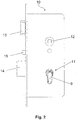
- Figure 2 shows an example of a side view of a known anti-panic mortise lock 10 with a device according to the invention mounted therein.
- Figure 3 equals to Figure 2 , shows the anti-panic mortise lock in a perspective view.
- a door locked by means of latch 13 and bolt 14 can be opened from the inside via a push actuation (actuation of the door handle) without using a key.
- the door can be unlocked from the inside and then opened without successful authentication (in panic situations).
- the door is also automatically locked after each door closing by means of a spring preload on the locking bolt.
- an opening or receptacle 11 is shown in which a lock cylinder can be inserted.
- it is the shape for a profile cylinder (PZ; see also Fig. 6 ).
- the device according to the invention is not limited to such locks or lock cases with profile cylinders and can also be used for Swiss round cylinders or other known cylinder shapes.
- the device for detecting the locking position is inserted into the corresponding opening 11 instead of a locking cylinder.
- the device covers the upper round section (see also "A" in Fig. 6 ) the opening 11 over an angular range of approximately 300 °.
- the device according to the invention preferably extends at least partially over the round (upper) section of the opening 11, so that in the section below (see "B” in FIG Fig. 6 ) a bracing element 203 or a wedge element 9 can be located.
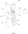
- FIG. 1 shows, for example, a fitting solution in which both the electronics and the mechanics for access control are arranged in the outer or inner fitting.
- the fitting 201 on the inside of the door comprises a handle 210 (inside door handle) which is fixedly coupled to the handle pin 204, which can be inserted into the nut 12 of the mortise lock.
- the fitting 200 also shows a corresponding outer fitting 202 with an outside lever 220.
- the outside lever 220 is coupled to the lever 204 of the inside fitting 201 via the modified lever pin 214.
- the inside handle pin 204 is always coupled to the nut 12 of the mortise lock, so that the anti-panic lock can always be opened when the inside handle is actuated.
- the outer handle pin 214 rotates without the inner handle 204 rotating, ie the outer door handle cannot actuate the mortise of the mortise lock, and the door is not opened from the outside. Only when authentication is successful are the two handles 204 and 214 coupled in such a way that a rotation of the outer handle 220 is transmitted to the inner handle pin 204, so that the door lock, ie the bolt and the latch, are opened.
- the fitting solution 220 shown is a special form of the fitting solution which is preferably attached to the door leaf without direct screwing.
- the outer and inner fittings are fastened here by means of a clamping element 203, which pulls or braces the outer and inner fittings against one another, this clamping element 203 preferably lying in the opening 11 of the mortise lock, which is provided for the locking cylinder.
- this clamping element 203 preferably lying in the opening 11 of the mortise lock, which is provided for the locking cylinder.
- the chipping element 203 of the embodiment in FIG Figure 1 has essentially a rectangular cross section, whereas the opening 11 in the mortise lock shown is a PZ opening, ie when a rectangular cross section is inserted, at least part of the upper cylindrical round part of the opening 11 remains free, even if the clamping element is arranged in the opening 11 ,
- the device according to the invention advantageously uses this space. In particular, it is precisely at this location of the mortise lock that contact or engagement with the bolt and / or the mechanism for actuating the bolt is possible, since a correspondingly arranged locking cylinder would actuate the bolt at this location with the help of the locking bar of the locking cylinder.
- the device according to the invention uses this special location to detect the locking position. In other words, the position of the bolt is determined from the inside within the mortise lock and not from the outside, as a result of which the device according to the invention is simple, safe and space-saving to assemble, ie the existing infrastructure can be used particularly advantageously.
- bracing element 203 it is preferred instead of the bracing element 203, insert a wedge 9 into the opening 11 of the mortise lock in order to ensure a secure fit of the device according to the invention in the opening 11 and preferably to prevent the device from rotating within the opening 11.
- a major preferred advantage of the present invention is that the device is roughly modeled on the outside of the conventional middle part of a lock cylinder with a lock bit and therefore, like this, can be inserted into a profile cylinder opening provided for this purpose, without modifications to a lock (ie the existing " Infrastructure ”) are required.
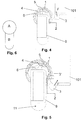
- the Figures 4 and 5 show the functioning of the device according to the invention on the basis of two different positions of the bolt or the locking mechanism 101.
- the device according to the invention comprises at least two parts 1 and 2 which can be rotated relative to one another.
- the first part is the inner part 1 and the second part is the outer part 2.
- the device can be described as a ring segment. Due to the expansion along the width of the lock case, the device could also be described as a cylinder segment, with a section that corresponds to a (round) cylinder wall over an angular range of approximately 200-300 °.
- the cross section of the device could also be referred to as "U-shaped" with a recess into which the bracing element 203 or the wedge 9 can be inserted in order to prevent the device from rotating within the opening 11.
- the inner part 2 and the outer part 1 are movable relative to one another, the inner part 2 preferably being mounted in the lock such that it cannot twist by means of the wedge 9 or the bracing element 203, so that in the mounted position only the outer part 1 remains relative to the lock case can move.
- the dimensions of this pushbutton element are modeled on a locking bit, so that the pushbutton element 3 according to the invention makes it possible to contact or engage in the locking mechanism as if a locking cylinder had been inserted into the opening 11.
- the feeler element 3 can be formed in one piece with the outer part 1 or fixedly attached to the outer part 1.
- the outer part 1 can have a fastening structure which is complementary to a fastening structure 3 ′ in the pushbutton element 3.
- that outer part 1 have a type of dovetail or backdrop structure into which corresponding "negative" shapes 3 ', which are formed in the probe element 3, can be inserted.
- the touch element 3 is preferably attached to the outer part 1 via a positive connection.
- This embodiment has the additional advantage that the sensing element 3 can be attached to the outer part 1 at different positions. The angular position of the feeler element 3 in the rest position can thus be set within certain limits.
- Fig. 4 shows a basic position. This basic position is detected by a sensor 6 present in the device.
- a rotation of two parts that can be rotated relative to one another can be detected by means of a large number of different sensors. Detection using a Hall sensor is particularly preferred.
- the Hall sensor 6 is preferably attached to the inner part 2 of the device.
- a Hall sensor can be present on a thin circuit board (for example a film circuit board), electronics for operating or evaluating the Hall sensor 6 already being present on the circuit board. Because of the electronics, it is preferred to attach the Hall sensor to the stationary part of the device, ie to the inner part 2. Because of the small size of the sensor, it is also possible to attach the sensor to the movable outer part 1.
- a small magnet is then attached to the other movable part and can be detected in a certain position with the Hall sensor 6.
- the small magnet 4 is attached to the outer part 1.
- the Hall sensor 6 is in the illustrated embodiment in Fig. 4 just below the magnet 4.
- the Hall sensor 6 detects the magnet 4 in this position; the latch position can accordingly be detected in accordance with the position of the component 101 which is part of the latch or part of the latch mechanism.
- the invention also includes the exact or exact terms, features, numerical values or ranges, etc., if above or below these terms, features, numerical values or ranges in connection with terms such as e.g. “approximately, approximately, um, essentially, generally, at least, at least” etc. (ie “approximately 3” should also include “3” or “substantially radial” should also include “radial”).
- the expression “or” also means “and / or”.
Landscapes
- Engineering & Computer Science (AREA)
- Structural Engineering (AREA)
- Business, Economics & Management (AREA)
- Emergency Management (AREA)
- Lock And Its Accessories (AREA)
Description
Die vorliegende Erfindung betrifft allgemein eine Vorrichtung zur Detektion einer Riegelstellung in einem Einsteckschloss. Speziell ist die erfindungsgemäße Vorrichtung dazu angepasst, die Riegelstellung in einem selbstverriegelnden Anti-Panikschloss zu detektieren. Zudem betrifft die Erfindung ein Verfahren zur Montage der erfindungsgemäßen Vorrichtung und auch ein Verfahren zur Detektion einer Riegelstellung.The present invention relates generally to a device for detecting a locking position in a mortise lock. The device according to the invention is specially adapted to detect the locking position in a self-locking anti-panic lock. In addition, the invention relates to a method for assembling the device according to the invention and also to a method for detecting a locking position.
Türen mit selbstverriegelnden Schlössern haben den Vorteil, dass sie stets abgeschlossen (verriegelt) sind. Fällt die Tür in Schloss, wird der geschlossene Zustand nicht nur durch die (relativ leicht manipulierbare) Falle sichergestellt; zusätzlich wird der Riegel automatisch mittels vorgespannter Feder in eine verriegelte Stellung geschoben. Andererseits wird bei Betätigung des Drückers von innen nicht nur die Falle, sondern auch der Riegel in eine entriegelte Stellung gebracht. Dies ist besonders wichtig für Fluchtwegtüren im Brand- oder Gefahrenfall.Doors with self-locking locks have the advantage that they are always locked. If the door locks, the closed state is not only ensured by the (relatively easy to manipulate) latch; in addition, the bolt is automatically pushed into a locked position by means of a preloaded spring. On the other hand, when the handle is actuated, not only the latch but also the bolt is brought into an unlocked position from the inside. This is particularly important for emergency exit doors in the event of fire or danger.
Selbstverriegelnde Schlösser können üblicherweise mit bekannten Schließzylindern kombiniert werden, wobei der Schließzylinder für die Feststellung der Zutrittsberechtigung von außen dient. So kann nur mit Hilfe eines passenden Schlüssels, d.h., nach erfolgreicher Feststellung der Zutrittsberechtigung ein Teil des Schließzylinders gedreht werden, der dann den Riegel und/oder die Falle des Schlosses betätigt. Schließzylinder können unter Verwendung von mechanischen Schlüsseln und/oder elektronischen Schlüsseln (Transpondern) eine Zutrittskontrolle feststellen.Self-locking locks can usually be combined with known locking cylinders, the locking cylinder being used to determine access authorization from the outside. Part of the locking cylinder can then only be turned with the help of a suitable key, i.e. after successful determination of the access authorization, which then actuates the bolt and / or the latch of the lock. Lock cylinders can determine access control using mechanical keys and / or electronic keys (transponders).
Anstelle die Zutrittsberechtigung mit Hilfe eines Schließzylinders durchzuführen gibt es auch die Möglichkeit, eine elektronische Zutrittskontrollfunktion teilweise oder sogar komplett in einen oder beide Seiten (außen und innen) eines Türbeschlags zu integrieren; ein gesonderter Schließzylinder ist in einem solchen Fall nicht mehr nötig. Oft wird von elektronisch gesicherten Türen erwartet, dass Informationen über ihren Verriegelungszustand einer zentralen Überwachungseinheit bereitgestellt werden, so dass ein sicherer Gebäudeverschluss auch ohne Wächterrundgang sichergestellt werden kann. Dazu ist eine Erfassung der Riegelposition und die Übertragung dieser Zustandsdaten über Netzwerke an die Zentrale erforderlich.Instead of access authorization using a locking cylinder, there is also the option of partially or even completely integrating an electronic access control function into one or both sides (outside and inside) of a door fitting; In such a case, a separate locking cylinder is no longer necessary. Electronically secured doors are often expected to provide information about their locked status to a central monitoring unit, so that a secure building lock can be ensured even without a guard tour. This requires the bolt position to be recorded and this status data to be transmitted to the control center via networks.
Alternativ zu mechanisch selbstverriegelnden Schlössern können Ver- und Entriegelungen auch durch motorische Antriebe bewerkstelligt werden. Hier sind Informationen über die aktuelle Riegelposition ein wichtiges Feedbacksignal an die Motorsteuerung.As an alternative to mechanically self-locking locks, locking and unlocking can also be achieved using motorized drives. Here, information about the current bolt position is an important feedback signal to the motor control.
Beispielsweise offenbart die Anmeldung
Gemäß den Druckschriften
Eine bevorzugte Aufgabe der vorliegenden Erfindung ist es, Nachteile bekannter Ansätze zum Ermitteln der Riegelstellung zu überwinden, und insbesondere Lösungen bereitzustellen, die im Wesentlichen vollständig in eine vorhandene Schließvorrichtung - auch nachträglich - integrierbar sind, so dass aufwendige Installations- und Verkabelungsarbeiten für das Anbringen externer Riegelsensoren entfallen.A preferred object of the present invention is to overcome disadvantages of known approaches for determining the locking position, and in particular to provide solutions which can be integrated substantially completely into an existing locking device, even subsequently, so that complex installation and cabling work for attaching external ones Bolt sensors are no longer required.
Die erfindungsgemäße Lösung soll also einfach zu montieren, aber auch einfach zu demontieren sein. Schließlich ist es bevorzugt, dass die erfindungsgemäße Vorrichtung nachträglich in bestehende Schlösser eingesetzt/eingebaut werden kann.The solution according to the invention should therefore be easy to assemble but also easy to disassemble. Finally, it is preferred that the device according to the invention can be subsequently inserted / installed in existing locks.
Die erfindungsgemäße Vorrichtung sowie das erfindungsgemäße Verfahren werden durch die Merkmale der unabhängigen Ansprüche definiert. Vorteilhafte Ausgestaltungen ergeben sich aus den Unteransprüchen.The device according to the invention and the method according to the invention are defined by the features of the independent claims. Advantageous configurations result from the subclaims.
Bevorzugte Ausführungsformen der vorliegenden Erfindung bzw. bevorzugte Merkmalskombinationen der vorliegenden Erfindung werden in den folgenden beispielhaften Ausführungen beschrieben.Preferred embodiments of the present invention or preferred combinations of features of the present invention are described in the following exemplary embodiments.
Die vorliegende Erfindung betrifft generell eine Vorrichtung zur Detektion einer Riegelstellung eines Einsteckschlosses. Ein Einsteckschloss, oft auch einfach als Schloss oder Schlosskasten bezeichnet, ist ein Türschloss mit Falle und Riegel. Bekannte Einsteckschlösser erfüllen die DIN 18 251 zum Einbau in Stumpftüren, Falztüren oder Rohrrahmentüren. Beispielsweise können Einsteckschlösser ein Buntbart-, Zuhaltungs-(Chubb-) oder Profilzylinderschließwerk haben. Die erfindungsgemäße Vorrichtung ist vorzugsweise als eine Art Nachrüstlösung zu sehen, die speziell dafür angepasst ist, in bestehende bekannte Einsteckschlösser eingesetzt zu werden. Beispielsweise ist in einem Profilzylinderschloss eine Öffnung vorhanden, in die ein Schließzylinder einsetzbar ist. Der Schließbart (oft auch als Schließnase bezeichnet) kommt bei eingesetztem Schließzylinder mit dem Mechanismus zum Betätigen des Riegels in Eingriff. Mit anderen Worten, der Schließbart ist das Bauteil eines Schließzylinders mit der Aufgabe, bei Drehung des Schließbarts den Riegel vor- und/oder zurückzuschieben, um die Tür zu verriegeln/entriegeln.The present invention relates generally to a device for detecting the locking position of a mortise lock. A mortise lock, often simply referred to as a lock or lock case, is a door lock with a latch and bolt. Known mortise locks comply with DIN 18 251 for installation in flush doors, rebate doors or tubular frame doors. For example, mortise locks can have a colored beard, tumbler (Chubb) or profile cylinder locking mechanism. The device according to the invention is preferably seen as a kind of retrofit solution that is specially adapted to be used in existing known mortise locks. For example, there is an opening in a cylinder lock in which a lock cylinder can be inserted. The lock bit (often also referred to as the locking lug) engages with the mechanism for actuating the bolt when the locking cylinder is inserted. In other words, the locking bar is the component of a locking cylinder with the task of pushing the bolt forward and / or back when the locking bar is rotated in order to lock / unlock the door.
Die erfindungsgemäße Vorrichtung ist besonders vorteilhaft in Verbindung mit einem Anti-Panikschloss. Bei einem normalen Panikschloss kann man immer von innen durch die Betätigung des Drückers (Türklinke) Falle und Riegel gleichzeitig zurückziehen. Dies bedeutet, dass eine richtig abgeschlossene (Falle und Riegel sind zu) Türanlage von innen über eine Drückerbetätigung geöffnet werden kann, ohne einen Schlüssel zu benutzen. Diese Art der Schlösser ist zusammengefasst unter dem Begriff Panikschloss (oft auch als Anti-Panikschloss bezeichnet). Nach der Betätigung eines Panikschlosses muss der Riegel manuell mit dem Schlüssel wieder ausgefahren werden. Eine Sonderlösung ist das selbstverriegelnde Panikschloss. Durch das Drücken der Klinke werden nicht nur die Falle und der Riegel eingezogen, sondern auch die interne Selbstverriegelungsmechanik vorgespannt. Sobald sich die Tür wieder schließt (zufällt), wird durch Betätigung einer zusätzlichen Steuerfalle, der Riegel wieder vorgeschoben. Dadurch ist die Tür immer mit Falle und Riegel verschlossen. Hierbei handelt es sich um eine rein mechanische Lösung, so dass keinerlei Stromzufuhr und eine damit verbundene Verkabelung notwendig ist.The device according to the invention is particularly advantageous in connection with an anti-panic lock. With a normal panic lock, you can always retract the latch and bolt from the inside by pressing the handle (doorknob). This means that a properly locked (latch and bolt are closed) door system can be opened from the inside using a lever handle without using a key. This type of lock is summarized under the term panic lock (often referred to as an anti-panic lock). After actuating a panic lock, the bolt must be extended manually with the key. The self-locking panic lock is a special solution. Pressing the latch not only pulls in the latch and bolt, it also preloads the internal self-locking mechanism. As soon as the door closes again (closes), the bolt is pushed again by actuating an additional control latch. As a result, the door is always locked with a latch and bolt. This is a purely mechanical solution, so that no power supply and no cabling is required.
In derartigen Schlössern ist es nicht somit notwendig, den Riegel mit Hilfe des Schließbartes von der offenen Stellung in die geschlossene Stellung zu überführen. Der Schließbart wird lediglich zum Öffnen des Riegels von außen benötigt. In sogenannten Beschlagslösungen kann dieser Öffnungsvorgang auch über Elektronik und Mechanik im Beschlag erreicht werden. Beispielsweise kann der Drückerstift von der Innentürklinke stets mit der Nuss des Einsteckschlosses in Wirkverbindung (gekoppelt) sein. Damit eine Betätigung des Außendrückers nur nach erfolgreicher Authentifizierung zur Betätigung des Riegels führt, kann eine Kupplung zwischen Außendrücker und Drückerstift hergestellt oder unterbrochen werden. Hat sich beispielsweise eine Person erfolgreich authentifiziert, dann wird eine temporäre Kopplung zwischen Außendrücker und Drückerstift hergestellt. Das Antipanikschloss funktioniert gewissermaßen so, als würde der stets fest mit der Nuss gekoppelte Innendrücker betätigt werden, d.h., die Tür lässt sich öffnen. Bei einer solchen Ausführungsform ist für die Authentifizierung kein Schließzylinder nötig, d.h., die vorhandene Öffnung im Schloss kann leer bleiben.In such locks it is therefore not necessary to move the bolt from the open position to the closed position with the help of the locking bit. The lock bit is only needed to open the bolt from the outside. In so-called fitting solutions, this opening process can also be achieved via electronics and mechanics in the fitting. For example, the handle pin of the inner door handle can always be operatively connected (coupled) to the nut of the mortise lock. To ensure that actuation of the outside handle only results in the bolt being actuated after successful authentication, a coupling between the outside handle and the handle pin can be established or interrupted. If, for example, a person has successfully authenticated, a temporary coupling is created between the outside handle and the handle pin. The anti-panic lock works, as it were, as if it were always firmly attached to the nut coupled inside handle, ie the door can be opened. In such an embodiment, a lock cylinder is not required for authentication, ie the existing opening in the lock can remain empty.
Genau hier setzt die erfindungsgemäße Vorrichtung an, d.h., die Vorrichtung ist dafür konfiguriert, dass sie anstelle eines Schließzylinders in der für den Schließzylinder vorgesehenen Öffnung des Einsteckschlosses einsetzbar ist und dort befestigt werden kann.This is exactly where the device according to the invention comes into play, i.e. the device is configured so that it can be used instead of a locking cylinder in the opening of the mortise lock provided for the locking cylinder and can be fastened there.
Vorzugsweise ist die erfindungsgemäße Vorrichtung teilweise den Maßen eines Schließzylinders nachempfunden. Zudem hat die erfindungsgemäße Vorrichtung zumindest ein Tastelement, das im Wesentlichen einem Schließbart/Schließnase eines Schließzylinders nachempfunden ist und mit dem Betätigungsmechanismus des Riegels bzw. dem Riegel des Einsteckschlosses in Eingriff oder zumindest in kommt. Erfindungsgemäß ist es ausreichend, wenn das Tastelement zumindest eine Position des Riegels ertasten kann. Beispielsweise kann es bereits ausreichend sein, wenn die geschlossene Position des Riegels erstastet werden kann. Hierzu reicht ein Kontakt des Tastelements mit dem Riegel bzw. dem Riegelmechanismus in dieser Position aus. Ändert sich die Riegelposition, dann wird auch die Lage des Tastelements verändert. Eine Veränderung der Riegelposition kann bereits festgestellt werden.The device according to the invention is preferably modeled in part on the dimensions of a locking cylinder. In addition, the device according to the invention has at least one pushbutton element, which is essentially modeled on a cam lock / locking lug of a locking cylinder and engages or at least comes in with the actuating mechanism of the bolt or the bolt of the mortise lock. According to the invention, it is sufficient if the feeler element can feel at least one position of the bolt. For example, it may already be sufficient if the closed position of the bolt can be felt. For this purpose, a contact of the feeler element with the bolt or the bolt mechanism in this position is sufficient. If the latch position changes, the position of the pushbutton element is also changed. A change in the latch position can already be determined.
Gemäß einer weiteren bevorzugten Ausführungsform kann auch zwischen einer offenen und verriegelten Position unterschieden werden, beispielsweise indem beide Positionen eindeutig detektiert werden (ertastet werden). Wenn der Riegel in der offenen Stellung ist wird dies mit dem Tastelement in einer ersten Position erfasst. Befindet sich der Riegel in der geschlossenen Stellung wird diese Veränderung ebenfalls vom Tastelement erfasst. Schließlich ist es gemäß einer weiteren bevorzugten Ausführungsform auch möglich Zwischenpositionen zu detektieren bzw. zu ertasten.According to a further preferred embodiment, a distinction can also be made between an open and locked position, for example in that both positions are clearly detected (sensed). If the bolt is in the open position, this is detected with the feeler element in a first position. If the bolt is in the closed position, this change is also detected by the feeler element. Finally, according to a further preferred embodiment, it is also possible to detect or feel intermediate positions.
Vorzugsweise ist das Tastelement ähnlich wie der Schließbart eines Schließzylinders drehbar gelagert, vorzugsweise drehbar um eine (virtuelle) Achse gelagert. Mit anderen Worten, wenn der Riegel eine Translation von der offenen Stellung in die geschlossene Stellung durchführt (und umgekehrt) wird dies in eine Drehbewegung des Tastelements übertragen. Das Tastelement befindet sich je nach Position des Riegels in einer anderen "Winkelposition". Diese Drehung und/oder zumindest eine Winkelposition des Tastelements kann mit Hilfe eines Sensors, der vorzugsweise an der Vorrichtung oder innerhalb der Vorrichtung angebracht ist, detektiert werden. Da die Vorrichtung vorzugsweise am Schloss verdrehsicher befestigt wird, entspricht die relative Verdrehung bzw. Winkelposition einer relativ zum Schloss veränderten Winkelposition.The feeler element is preferably rotatably mounted, similar to the lock bit of a lock cylinder, preferably rotatably mounted about a (virtual) axis. In other words, when the bolt carries out a translation from the open position into the closed position (and vice versa), this is translated into a rotary movement of the feeler element. The probe element is in a different "angular position" depending on the position of the bolt. This rotation and / or at least one angular position of the feeler element can be detected with the aid of a sensor, which is preferably attached to the device or within the device. Since the device is preferably on the lock is secured against rotation, the relative rotation or angular position corresponds to an angular position changed relative to the lock.
Vorzugsweise umfasst die erfindungsgemäße Vorrichtung zumindest zwei zueinander bewegliche (verdrehbare) Teile, die vorzugsweise aus Kunststoff hergestellt sind. Zudem ist es bevorzugt, dass ein Teil in Bezug auf die Drehbewegung innen ist und das zweite Teil zumindest teilweise außerhalb des inneren Teils beweglich ist. Vorzugsweise dreht sich das äußere Teil teilweise um das innere Teil. Es sollte jedoch beachtet werden, dass der Begriff "Drehbewegung" nicht gleichzusetzen ist mit einer vollen (360°) Drehung; vielmehr reicht es erfindungsgemäß, wenn die beiden Teile über einen kleinen Winkelbereich, beispielsweise 10°, 20°, 30°, 40°, 50° drehbar zueinander ausgeführt sind.The device according to the invention preferably comprises at least two mutually movable (rotatable) parts, which are preferably made of plastic. In addition, it is preferred that one part is inner with respect to the rotational movement and the second part is at least partially movable outside the inner part. Preferably the outer part rotates partially around the inner part. However, it should be noted that the term "rotary motion" is not synonymous with a full (360 °) rotation; rather, it is sufficient according to the invention if the two parts are designed to be rotatable relative to one another over a small angular range, for example 10 °, 20 °, 30 °, 40 °, 50 °.
Die beiden Teile sind vorzugsweise Ringförmig ausgestaltent, d.h., mit einem inneren Ringelement und einem äußeren Ringelement, wobei sich die Ringelemente vorzugsweise nicht über den gesamten Umlauf von 360° erstrecken. Vielmehr handelt es sich bei den erfindungsgemäßen Ringelementen um "teilweise" Ringelemente bzw. Ringsegmente.The two parts are preferably designed in the form of a ring, i.e. with an inner ring element and an outer ring element, the ring elements preferably not extending over the entire circumference of 360 °. Rather, the ring elements according to the invention are “partially” ring elements or ring segments.
Gemäß einer weiteren bevorzugten Ausführungsform sind die beiden zueinander beweglichen Teile durch eine dazwischenliegende Feder vorgespannt bzw. belastet. Wenn keine äußere Kraft auf das Tastelement wirkt befindet sich das Tastelement vorzugsweise in einer Ausgangsstellung. Vorzugsweise entspricht diese Ausgangsstellung der Stellung, die der entriegelten Riegelstellung entspricht. Gemäß einer anderen Ausführungsform kann diese Ausgangsstellung auch der verschlossenen Riegelstellung entsprechen. Die Feder die auf das Tastelement eine Kraft ausübt bewirkt somit, dass das Tastelement gegen ein Teil des Riegels bzw. des Riegelmechanismus drückt. Vorzugsweise ist diese Federkraft so klein, dass der Schließmechanismus des selbstverriegelnden Anti-Pantikschlosses nicht negativ beeinflusst wird, d.h., die Federkraft des Anti-Pantikschlosses zur automatischen ausfahren des Riegels wird durch die Tastfederkraft nicht gehemmt. Die Tastfederkraft ist lediglich so groß, dass sichergestellt wird, dass das Tastelement in der entsprechenden zu detektierenden Position in Kontakt mit dem Riegel bzw. dem Riegelmechanismus kommt.According to a further preferred embodiment, the two parts which are movable relative to one another are biased or loaded by an intermediate spring. If no external force acts on the probe element, the probe element is preferably in an initial position. This starting position preferably corresponds to the position which corresponds to the unlocked locking position. According to another embodiment, this starting position can also correspond to the locked locking position. The spring which exerts a force on the feeler element thus causes the feeler element to press against part of the bolt or the locking mechanism. This spring force is preferably so small that the locking mechanism of the self-locking anti-panty lock is not adversely affected, i.e. the spring force of the anti-panty lock for automatically extending the bolt is not inhibited by the key spring force. The touch spring force is only so great that it is ensured that the touch element comes into contact with the bolt or the locking mechanism in the corresponding position to be detected.
Gemäß einer besonders bevorzugten Ausführungsform wird als Feder eine Magazinfeder verwendet, die vorzugsweise eine rechteckige Grundfläche hat. Der Bauraum von ovalen bzw. rechteckigen Magazinfedern wird besonders vorteilhaft ausgenützt, so dass Wände die Funktion einer Führung übernehmen können. So kann beispielsweise in einem Zwischenraum zwischen dem äußeren Teil und dem inneren Teil eine Magzinfeder eingesetzt werden, wobei die Wände des äußeren und inneren Teils die zur Feder gerichteten sind, die Funktion einer Führung übernehmen.According to a particularly preferred embodiment, a magazine spring is used as the spring, which preferably has a rectangular base. The installation space of oval or rectangular magazine springs is used particularly advantageously, so that walls can act as guides. For example, a magnesium spring can be used in a space between the outer part and the inner part are, with the walls of the outer and inner part facing the spring, take over the function of a guide.
Gemäß anderen Ausführungsformen können auch andere Federn verwendet werden, beispielsweise Spiralfedern oder Schenkelfedern.According to other embodiments, other springs can also be used, for example spiral springs or leg springs.
Gemäß einer besonderen Ausführungsform ist die erfindungsgemäße Vorrichtung speziell an eine Beschlagslösung angepasst, bei der die beiden Beschlagsseiten nicht mit dem Türblatt verschraubt werden müssen (siehe
Alternativ kann auch anstelle des Verspannelements ein zusätzliches Keilelement in die Öffnung für den Schließzylinder eingesetzt werden. Dies bietet sich beispielsweise für Beschlagslösungen an, bei denen die Beschläge traditionell mit dem Türblatt verschraubt werden, d.h., wenn die Öffnung für den Schließzylinder frei bleibt.Alternatively, an additional wedge element can also be inserted into the opening for the locking cylinder instead of the bracing element. This is useful, for example, for fitting solutions in which the fittings are traditionally screwed to the door leaf, i.e. if the opening for the locking cylinder remains free.
Schließlich betrifft die vorliegende Erfindung auch ein Verfahren zur Detektion einer Riegelstellung eines Einsteckschlosses mit den Schritten: Bereitstellen einer erfindungsgemäßen Vorrichtung und Einsetzen der Vorrichtung in die Öffnung des Einsteckschlosses, das zur Aufnahme eines Schließzylinders vorgesehenen ist anstelle eines Schließzylinders und Auslesen der Signale des Sensors, um zu Bestimmen, ob der Riegel in einer offenen oder geschlossenen Stellung ist.Finally, the present invention also relates to a method for detecting the locking position of a mortise lock, comprising the steps of: providing a device according to the invention and inserting the device into the opening of the mortise lock, which is provided for receiving a locking cylinder instead of a locking cylinder and reading out the signals from the sensor to determine whether the latch is in an open or closed position.
Im Folgenden werden bevorzugte Ausführungsformen der vorliegenden Erfindung unter Bezugnahme auf die Figuren ausführlich beschrieben. Es zeigen:
- Fig. 1
- einen Türbeschlag mit integrierter Elektronik und Mechanik zur Detektion und Steuerung einer Zutrittsberechtigung;
- Fig. 2
- in einer Seitenansicht einen Schlosskasten aus dem Stand der Technik mit einer erfindungsgemäßen Vorrichtung in der Öffnung die für einen PZ-Schließzylinder vorgesehen ist;
- Fig. 3
- eine der der
Fig 2 entsprechende, jedoch perspektivische Ansicht; - Fig. 4
- das Tastelement in der entriegelten Stellung;
- Fig. 5
- mit dem Tastelement in der verriegelten Stellung; und
- Fig. 6
- nicht maßstabsgetreu die Form eines Profilzylinders.
- Fig. 1
- a door fitting with integrated electronics and mechanics for the detection and control of an access authorization;
- Fig. 2
- in a side view a lock case from the prior art with a device according to the invention in the opening which is provided for a cylinder lock cylinder;
- Fig. 3
- one of the
Fig. 2 corresponding, but perspective view; - Fig. 4
- the pushbutton in the unlocked position;
- Fig. 5
- with the pushbutton in the locked position; and
- Fig. 6
- not to scale the shape of a profile cylinder.
Wie einleitend beschrieben, betrifft die Erfindung eine Vorrichtung zur Detektion einer Riegelstellung eines Einsteckschlosses 10, speziell eines selbstverriegelnden Anti-Panikschlosses.
Bei einem normalen Panikschloss kann man immer durch die Betätigung des Innendrückers 210 (siehe
In den
Die erfindungsgemäße Vorrichtung wird insbesondere dann eingesetzt, wenn ein Schließzylinder nicht in die dafür vorgesehene Schließzylinderöffnung 11 einzusetzen ist.
Es sollte jedoch hervorgehobenen werden, dass die in
Ein wesentlicher bevorzugter Vorteil der vorliegenden Erfindung ist darin zu sehen, dass die Vorrichtung äußerlich dem herkömmlichen Mittelteil eines Schließzylinders mit Schließbart grob nachempfunden ist und daher wie dieser in eine dafür vorgesehene Profilzylinderöffnung eingesetzt werden kann, ohne dass dabei Modifikationen eines Schlosses (d.h. der vorhandenen "Infrastruktur") erforderlich sind.A major preferred advantage of the present invention is that the device is roughly modeled on the outside of the conventional middle part of a lock cylinder with a lock bit and therefore, like this, can be inserted into a profile cylinder opening provided for this purpose, without modifications to a lock (ie the existing " Infrastructure ") are required.
Die
Das innere Teil 2 und das äußere Teil 1 sind relativ zueinander beweglich, wobei vorzugsweise der innere Teil 2 durch den Keil 9 bzw. das Verspannelement 203 verdrehsicher im Schloss angebracht wird, sodass sich in der montierten Position nur noch das äußere Teil 1 relativ zum Schlosskasten bewegen lässt. Am äußeren Teil ist das Tastelement 3 angebracht, das einem Schließbart eines Schließzylinders nachempfunden ist. Insbesondere sind die Maße dieses Tastelements einem Schließbart nachempfunden, sodass mit dem erfindungsgemäßen Tastelement 3 ein Kontakt bzw. Eingriff in den Riegelmechanismus möglich ist, als ob ein Schließzylinder in die Öffnung 11 eingesetzt wäre. Gemäß einer Ausführungsform kann das Tastelement 3 einstückig mit dem äußeren Teil 1 ausgebildet sein oder fest am äußeren Teil 1 befestigt sein. Gemäß einer weiteren bevorzugten Ausführungsform kann das äußere Teil 1 eine Befestigungsstruktur aufweisen, die komplementär zu einer Befestigungsstruktur 3' im Tastelement 3 ist. Beispielsweise kann das äußere Teil 1 eine Art Schwalbenschwanz- oder Kulissenstruktur aufweisen in die entsprechende "negative" Formen 3', die im Tastelement 3 ausgebildet sind, eingefügt werden können. Eine Anbringung des Tastelements 3 an dem äußeren Teil 1 erfolgt vorzugsweise über einen Formschluss. Diese Ausführungsform hat den zusätzlichen Vorteil, dass das Tastelement 3 an unterschiedlichen Positionen am äußeren Teil 1 angebracht werden kann. Somit kann die Winkelposition des Tastelements 3 in der Ruheposition innerhalb gewisser Grenzen eingestellt werden.The
Um einen Kontakt zum Riegelmechanismus 101 des Schlosses 10 zu gewährleisten ist es vorteilhaft, wenn das Tastelement 3 gegen den Riegelmechanismus mit einer geringen Kraft F (Tastkraft) gedrückt wird. Diese Kraft wird durch eine Feder erzeugt, die in dem Zwischenraum 5 liegt, der zwischen dem Innenteil 2 und dem Außenteil 1 ausgebildet ist. Es hat sich gezeigt, dass es besonders vorteilhaft ist, eine Magazinfeder ähnlich wie sie bei Waffenmagazinen verwendet wird, in den Zwischenraum 5 einzusetzen.In order to ensure contact with the
Am anderen beweglichen Teil wird dann ein kleiner Magnet befestigt, der mit dem Hallsensor 6 in einer bestimmten Position detektiert werden kann. In den
In der
Die Erfindung umfasst ebenfalls die genauen oder exakten Ausdrücke, Merkmale, numerischen Werte oder Bereiche usw., wenn vorstehend oder nachfolgend diese Ausdrücke, Merkmale, numerischen Werte oder Bereiche im Zusammenhang mit Ausdrücken wie z.B. "etwa, ca., um, im Wesentlichen, im Allgemeinen, zumindest, mindestens" usw. genannt wurden (also "etwa 3" soll ebenfalls "3" oder "im Wesentlichen radial" soll auch "radial" umfassen). Der Ausdruck "bzw." bedeutet überdies "und/oder".The invention also includes the exact or exact terms, features, numerical values or ranges, etc., if above or below these terms, features, numerical values or ranges in connection with terms such as e.g. "approximately, approximately, um, essentially, generally, at least, at least" etc. (ie "approximately 3" should also include "3" or "substantially radial" should also include "radial"). The expression "or" also means "and / or".
Claims (16)
- A device for detecting a dead bolt position of a mortise lock (10), configured to be attached to an opening (11) of the mortise lock (10) which is provided for a locking cylinder instead of a locking cylinder with:a touch element (3) which is in contact with the operating mechanism of the dead bolt or the dead bolt (14) of the mortise lock (10), wherein the touch element (3) is rotatably mounted,and wherein a rotation of the touch element (3) is detected by a sensor (2).
- The device according to claim 1, wherein the touch element (3) is pushed against the operating mechanism of the dead bolt or the dead bolt (14) by a force, wherein, however, said force is preferably smaller than the force by which the dead bolt of the mortise lock (10) is pushed outwards during a locking.
- The device according to claim 1 or 2, wherein the touch element (3) is substantially a recreation of the bolt toe of a locking cylinder.
- The device according to any one of the preceding claims, wherein the mortise lock (10) is a self-locking anti-panic mortise lock (10).
- The device according to any one of the preceding claims, wherein the device comprises two components (1, 2) which are moveable with respect to each other and which are preferably made of plastic.
- The device according to claim 5, wherein both components (1, 2) which are moveable with respect to each other are forced into a starting position by an intermediate spring (5), the starting position preferably corresponding to the unlocked dead bolt position.
- The device according to claim 6, wherein the spring is a magazine spring (5) having preferably a square base area.
- The device according to any one of the preceding claims, wherein the device is adapted to be mounted in the opening (11) in addition to a tensioning element (203) which tensions two halves of the door fitting assembly (201, 202) against a door leaf and lies within said opening (11) of the mortise lock (10) provided for the locking cylinder.
- The device according to any one of the preceding claims, wherein the device fills in the opening (11) only partially, preferably less than 50% and an additional wedge element (9) is insertable into the opening (11) in addition to the device to secure the device against twisting relative to the mortise lock when the dead bolt (12) is operated.
- The device according to any one of the preceding claims, wherein the touch element (3) is rotated depending on a change of the dead bolt position of the mortise lock.
- The device according to any one of the preceding claims, if dependent on claim 5, wherein the first component (1) of both components (1, 2) is an outer ring element (1) and connected to the touch element (3) and the outer ring element (1) is rotatably mounted outside of the second component (2) which is a core element (2).
- The device according to claims 6 and 11, wherein the spring (5) lies between the outer ring element (1) and the core element (2) and generates a relative rotation force with respect to these two elements.
- The device according to any one of claims 11 or 12, whereini) the touch element (3) is configured integrally with the outer ring element (1) orii) the touch element (3) is releasably mountable at the outer ring element (1), preferably by means of engaging profile elements at the ring element (1) and touch element (3), whereby the touch element (3) can be positioned in different angle positions on the ring element (1) to enable an adaptation to different lock types which require different angle positions.
- The device according to any one of the preceding claims, if dependent on claim 5, wherein the sensor (2) is a Hall sensor which is mounted in the first or second component and the other of the first and second component comprises a magnet (4) which can be detected by the Hall sensor.
- A method for detecting a dead bolt position of a mortise lock (10) with the steps of:- providing a device according to any one of the preceding claims,- inserting the device into the opening (11) of the mortise lock (10) which is provided for receiving a locking cylinder instead of a locking cylinder.
- The method according to claim 15 with the additional step of inserting a wedge element (9) to prevent a twisting of the device within the opening (11).
Applications Claiming Priority (1)
| Application Number | Priority Date | Filing Date | Title |
|---|---|---|---|
| DE102015006422 | 2015-05-19 |
Publications (2)
| Publication Number | Publication Date |
|---|---|
| EP3095934A1 EP3095934A1 (en) | 2016-11-23 |
| EP3095934B1 true EP3095934B1 (en) | 2019-12-18 |
Family
ID=56014921
Family Applications (1)
| Application Number | Title | Priority Date | Filing Date |
|---|---|---|---|
| EP16170178.4A Active EP3095934B1 (en) | 2015-05-19 | 2016-05-18 | Device for detecting a locking position |
Country Status (1)
| Country | Link |
|---|---|
| EP (1) | EP3095934B1 (en) |
Families Citing this family (2)
| Publication number | Priority date | Publication date | Assignee | Title |
|---|---|---|---|---|
| SE544588C2 (en) * | 2019-02-20 | 2022-09-13 | Bring Alot Konsult Ab | Switch arrangement with a triggering element and a sensor for being arranged in a locking mechanism and related system |
| CN111739187A (en) * | 2020-07-17 | 2020-10-02 | 广东樱花智能科技有限公司 | Automatic testing equipment and testing method for intelligent lock |
Family Cites Families (5)
| Publication number | Priority date | Publication date | Assignee | Title |
|---|---|---|---|---|
| CH695160A5 (en) | 1999-01-20 | 2005-12-30 | Kaba Schliesssysteme Ag | Bolt monitoring. |
| WO2010088611A1 (en) * | 2009-01-30 | 2010-08-05 | Corbin Russwin Architectural Hardware | Lock cylinder monitor |
| WO2011023814A1 (en) * | 2009-08-28 | 2011-03-03 | Simonsvoss Technologies Ag | Door fitting |
| DE102012025474B4 (en) * | 2012-12-29 | 2015-01-15 | Klaus Meister | Door and latch state detection device |
| DE102013103515A1 (en) * | 2013-04-09 | 2014-10-09 | Keba Ag | Charging connection device for electric vehicles |
-
2016
- 2016-05-18 EP EP16170178.4A patent/EP3095934B1/en active Active
Non-Patent Citations (1)
| Title |
|---|
| None * |
Also Published As
| Publication number | Publication date |
|---|---|
| EP3095934A1 (en) | 2016-11-23 |
Similar Documents
| Publication | Publication Date | Title |
|---|---|---|
| EP2703585B2 (en) | Passive wing locking device with an actuation rod arrangement having a manipulation protection device | |
| EP3309333B1 (en) | Arrangement with a blind frame for storing a wing frame | |
| EP3219886B1 (en) | Anti-panic push bar with drive device | |
| EP2391786B1 (en) | Lock-box | |
| EP2924202A1 (en) | Lock for a door or window | |
| DE102008063061A1 (en) | Actuating device for electronic door lock, has coupling pins engaged in coupling recess in unlock condition, and torque proof connection between outer wall and coupling arrangement supported by engagement of coupling pins in recess | |
| DE102014112122A1 (en) | Method for locking and releasing a door leaf and door arrangement | |
| EP2525025B1 (en) | Electronic unit for a blocking device and locking system | |
| DE202011103840U1 (en) | Locking system with multiple locking for one door | |
| EP3045623B1 (en) | Safety device for a door | |
| EP3095934B1 (en) | Device for detecting a locking position | |
| EP3034719B1 (en) | Actuating device for a locking mechanism of a door or a window | |
| EP2679751A2 (en) | Locking device and wing or leaf assembly equipped with the same | |
| EP1908899A2 (en) | Locking system | |
| EP2060710B1 (en) | Lock | |
| EP2862992B1 (en) | Multi-lock | |
| EP3219887A1 (en) | Universal anti-panic pressure rod | |
| EP3312369B1 (en) | Closure element of an immovable product and corresponding method | |
| EP2924206B1 (en) | Lock for a door or window | |
| DE102015119233B4 (en) | Security device for a door | |
| EP2738324A2 (en) | Lock with a releasable rotating unit | |
| EP3892802B1 (en) | Door handle | |
| DE102016122551A1 (en) | Sash frame of a window or door | |
| AT511829A4 (en) | Locking device and pipe safe with a locking device | |
| DE102016012604A1 (en) | Lock for a closure element of a real estate, closure element with lock system and method for carrying out a normal unlocking and an emergency unlocking |
Legal Events
| Date | Code | Title | Description |
|---|---|---|---|
| PUAI | Public reference made under article 153(3) epc to a published international application that has entered the european phase |
Free format text: ORIGINAL CODE: 0009012 |
|
| AK | Designated contracting states |
Kind code of ref document: A1 Designated state(s): AL AT BE BG CH CY CZ DE DK EE ES FI FR GB GR HR HU IE IS IT LI LT LU LV MC MK MT NL NO PL PT RO RS SE SI SK SM TR |
|
| AX | Request for extension of the european patent |
Extension state: BA ME |
|
| STAA | Information on the status of an ep patent application or granted ep patent |
Free format text: STATUS: REQUEST FOR EXAMINATION WAS MADE |
|
| 17P | Request for examination filed |
Effective date: 20170523 |
|
| RBV | Designated contracting states (corrected) |
Designated state(s): AL AT BE BG CH CY CZ DE DK EE ES FI FR GB GR HR HU IE IS IT LI LT LU LV MC MK MT NL NO PL PT RO RS SE SI SK SM TR |
|
| RIC1 | Information provided on ipc code assigned before grant |
Ipc: E05B 17/22 20060101AFI20190514BHEP Ipc: E05B 65/10 20060101ALI20190514BHEP Ipc: E05B 47/00 20060101ALN20190514BHEP Ipc: E05B 63/08 20060101ALI20190514BHEP Ipc: E05B 63/20 20060101ALI20190514BHEP |
|
| GRAP | Despatch of communication of intention to grant a patent |
Free format text: ORIGINAL CODE: EPIDOSNIGR1 |
|
| STAA | Information on the status of an ep patent application or granted ep patent |
Free format text: STATUS: GRANT OF PATENT IS INTENDED |
|
| INTG | Intention to grant announced |
Effective date: 20190621 |
|
| GRAS | Grant fee paid |
Free format text: ORIGINAL CODE: EPIDOSNIGR3 |
|
| GRAJ | Information related to disapproval of communication of intention to grant by the applicant or resumption of examination proceedings by the epo deleted |
Free format text: ORIGINAL CODE: EPIDOSDIGR1 |
|
| GRAL | Information related to payment of fee for publishing/printing deleted |
Free format text: ORIGINAL CODE: EPIDOSDIGR3 |
|
| STAA | Information on the status of an ep patent application or granted ep patent |
Free format text: STATUS: REQUEST FOR EXAMINATION WAS MADE |
|
| GRAR | Information related to intention to grant a patent recorded |
Free format text: ORIGINAL CODE: EPIDOSNIGR71 |
|
| STAA | Information on the status of an ep patent application or granted ep patent |
Free format text: STATUS: GRANT OF PATENT IS INTENDED |
|
| GRAA | (expected) grant |
Free format text: ORIGINAL CODE: 0009210 |
|
| STAA | Information on the status of an ep patent application or granted ep patent |
Free format text: STATUS: THE PATENT HAS BEEN GRANTED |
|
| INTG | Intention to grant announced |
Effective date: 20191107 |
|
| RIC1 | Information provided on ipc code assigned before grant |
Ipc: E05B 17/22 20060101AFI20191107BHEP Ipc: E05B 65/10 20060101ALI20191107BHEP Ipc: E05B 63/20 20060101ALI20191107BHEP Ipc: E05B 47/00 20060101ALN20191107BHEP Ipc: E05B 63/08 20060101ALI20191107BHEP |
|
| AK | Designated contracting states |
Kind code of ref document: B1 Designated state(s): AL AT BE BG CH CY CZ DE DK EE ES FI FR GB GR HR HU IE IS IT LI LT LU LV MC MK MT NL NO PL PT RO RS SE SI SK SM TR |
|
| REG | Reference to a national code |
Ref country code: CH Ref legal event code: EP |
|
| REG | Reference to a national code |
Ref country code: IE Ref legal event code: FG4D Free format text: LANGUAGE OF EP DOCUMENT: GERMAN |
|
| REG | Reference to a national code |
Ref country code: DE Ref legal event code: R096 Ref document number: 502016008035 Country of ref document: DE |
|
| REG | Reference to a national code |
Ref country code: AT Ref legal event code: REF Ref document number: 1214755 Country of ref document: AT Kind code of ref document: T Effective date: 20200115 |
|
| REG | Reference to a national code |
Ref country code: NL Ref legal event code: MP Effective date: 20191218 |
|
| PG25 | Lapsed in a contracting state [announced via postgrant information from national office to epo] |
Ref country code: FI Free format text: LAPSE BECAUSE OF FAILURE TO SUBMIT A TRANSLATION OF THE DESCRIPTION OR TO PAY THE FEE WITHIN THE PRESCRIBED TIME-LIMIT Effective date: 20191218 Ref country code: BG Free format text: LAPSE BECAUSE OF FAILURE TO SUBMIT A TRANSLATION OF THE DESCRIPTION OR TO PAY THE FEE WITHIN THE PRESCRIBED TIME-LIMIT Effective date: 20200318 Ref country code: NO Free format text: LAPSE BECAUSE OF FAILURE TO SUBMIT A TRANSLATION OF THE DESCRIPTION OR TO PAY THE FEE WITHIN THE PRESCRIBED TIME-LIMIT Effective date: 20200318 Ref country code: SE Free format text: LAPSE BECAUSE OF FAILURE TO SUBMIT A TRANSLATION OF THE DESCRIPTION OR TO PAY THE FEE WITHIN THE PRESCRIBED TIME-LIMIT Effective date: 20191218 Ref country code: LV Free format text: LAPSE BECAUSE OF FAILURE TO SUBMIT A TRANSLATION OF THE DESCRIPTION OR TO PAY THE FEE WITHIN THE PRESCRIBED TIME-LIMIT Effective date: 20191218 Ref country code: LT Free format text: LAPSE BECAUSE OF FAILURE TO SUBMIT A TRANSLATION OF THE DESCRIPTION OR TO PAY THE FEE WITHIN THE PRESCRIBED TIME-LIMIT Effective date: 20191218 Ref country code: GR Free format text: LAPSE BECAUSE OF FAILURE TO SUBMIT A TRANSLATION OF THE DESCRIPTION OR TO PAY THE FEE WITHIN THE PRESCRIBED TIME-LIMIT Effective date: 20200319 |
|
| REG | Reference to a national code |
Ref country code: LT Ref legal event code: MG4D |
|
| PG25 | Lapsed in a contracting state [announced via postgrant information from national office to epo] |
Ref country code: HR Free format text: LAPSE BECAUSE OF FAILURE TO SUBMIT A TRANSLATION OF THE DESCRIPTION OR TO PAY THE FEE WITHIN THE PRESCRIBED TIME-LIMIT Effective date: 20191218 Ref country code: RS Free format text: LAPSE BECAUSE OF FAILURE TO SUBMIT A TRANSLATION OF THE DESCRIPTION OR TO PAY THE FEE WITHIN THE PRESCRIBED TIME-LIMIT Effective date: 20191218 |
|
| PG25 | Lapsed in a contracting state [announced via postgrant information from national office to epo] |
Ref country code: AL Free format text: LAPSE BECAUSE OF FAILURE TO SUBMIT A TRANSLATION OF THE DESCRIPTION OR TO PAY THE FEE WITHIN THE PRESCRIBED TIME-LIMIT Effective date: 20191218 |
|
| PG25 | Lapsed in a contracting state [announced via postgrant information from national office to epo] |
Ref country code: NL Free format text: LAPSE BECAUSE OF FAILURE TO SUBMIT A TRANSLATION OF THE DESCRIPTION OR TO PAY THE FEE WITHIN THE PRESCRIBED TIME-LIMIT Effective date: 20191218 Ref country code: RO Free format text: LAPSE BECAUSE OF FAILURE TO SUBMIT A TRANSLATION OF THE DESCRIPTION OR TO PAY THE FEE WITHIN THE PRESCRIBED TIME-LIMIT Effective date: 20191218 Ref country code: EE Free format text: LAPSE BECAUSE OF FAILURE TO SUBMIT A TRANSLATION OF THE DESCRIPTION OR TO PAY THE FEE WITHIN THE PRESCRIBED TIME-LIMIT Effective date: 20191218 Ref country code: PT Free format text: LAPSE BECAUSE OF FAILURE TO SUBMIT A TRANSLATION OF THE DESCRIPTION OR TO PAY THE FEE WITHIN THE PRESCRIBED TIME-LIMIT Effective date: 20200513 Ref country code: CZ Free format text: LAPSE BECAUSE OF FAILURE TO SUBMIT A TRANSLATION OF THE DESCRIPTION OR TO PAY THE FEE WITHIN THE PRESCRIBED TIME-LIMIT Effective date: 20191218 |
|
| PG25 | Lapsed in a contracting state [announced via postgrant information from national office to epo] |
Ref country code: SM Free format text: LAPSE BECAUSE OF FAILURE TO SUBMIT A TRANSLATION OF THE DESCRIPTION OR TO PAY THE FEE WITHIN THE PRESCRIBED TIME-LIMIT Effective date: 20191218 Ref country code: SK Free format text: LAPSE BECAUSE OF FAILURE TO SUBMIT A TRANSLATION OF THE DESCRIPTION OR TO PAY THE FEE WITHIN THE PRESCRIBED TIME-LIMIT Effective date: 20191218 Ref country code: IS Free format text: LAPSE BECAUSE OF FAILURE TO SUBMIT A TRANSLATION OF THE DESCRIPTION OR TO PAY THE FEE WITHIN THE PRESCRIBED TIME-LIMIT Effective date: 20200418 |
|
| REG | Reference to a national code |
Ref country code: DE Ref legal event code: R097 Ref document number: 502016008035 Country of ref document: DE |
|
| PLBE | No opposition filed within time limit |
Free format text: ORIGINAL CODE: 0009261 |
|
| STAA | Information on the status of an ep patent application or granted ep patent |
Free format text: STATUS: NO OPPOSITION FILED WITHIN TIME LIMIT |
|
| PG25 | Lapsed in a contracting state [announced via postgrant information from national office to epo] |
Ref country code: DK Free format text: LAPSE BECAUSE OF FAILURE TO SUBMIT A TRANSLATION OF THE DESCRIPTION OR TO PAY THE FEE WITHIN THE PRESCRIBED TIME-LIMIT Effective date: 20191218 Ref country code: ES Free format text: LAPSE BECAUSE OF FAILURE TO SUBMIT A TRANSLATION OF THE DESCRIPTION OR TO PAY THE FEE WITHIN THE PRESCRIBED TIME-LIMIT Effective date: 20191218 |
|
| 26N | No opposition filed |
Effective date: 20200921 |
|
| PG25 | Lapsed in a contracting state [announced via postgrant information from national office to epo] |
Ref country code: SI Free format text: LAPSE BECAUSE OF FAILURE TO SUBMIT A TRANSLATION OF THE DESCRIPTION OR TO PAY THE FEE WITHIN THE PRESCRIBED TIME-LIMIT Effective date: 20191218 |
|
| PG25 | Lapsed in a contracting state [announced via postgrant information from national office to epo] |
Ref country code: LI Free format text: LAPSE BECAUSE OF NON-PAYMENT OF DUE FEES Effective date: 20200531 Ref country code: CH Free format text: LAPSE BECAUSE OF NON-PAYMENT OF DUE FEES Effective date: 20200531 Ref country code: MC Free format text: LAPSE BECAUSE OF FAILURE TO SUBMIT A TRANSLATION OF THE DESCRIPTION OR TO PAY THE FEE WITHIN THE PRESCRIBED TIME-LIMIT Effective date: 20191218 Ref country code: IT Free format text: LAPSE BECAUSE OF FAILURE TO SUBMIT A TRANSLATION OF THE DESCRIPTION OR TO PAY THE FEE WITHIN THE PRESCRIBED TIME-LIMIT Effective date: 20191218 |
|
| PG25 | Lapsed in a contracting state [announced via postgrant information from national office to epo] |
Ref country code: PL Free format text: LAPSE BECAUSE OF FAILURE TO SUBMIT A TRANSLATION OF THE DESCRIPTION OR TO PAY THE FEE WITHIN THE PRESCRIBED TIME-LIMIT Effective date: 20191218 |
|
| REG | Reference to a national code |
Ref country code: BE Ref legal event code: MM Effective date: 20200531 |
|
| GBPC | Gb: european patent ceased through non-payment of renewal fee |
Effective date: 20200518 |
|
| PG25 | Lapsed in a contracting state [announced via postgrant information from national office to epo] |
Ref country code: LU Free format text: LAPSE BECAUSE OF NON-PAYMENT OF DUE FEES Effective date: 20200518 |
|
| PG25 | Lapsed in a contracting state [announced via postgrant information from national office to epo] |
Ref country code: IE Free format text: LAPSE BECAUSE OF NON-PAYMENT OF DUE FEES Effective date: 20200518 Ref country code: GB Free format text: LAPSE BECAUSE OF NON-PAYMENT OF DUE FEES Effective date: 20200518 |
|
| PG25 | Lapsed in a contracting state [announced via postgrant information from national office to epo] |
Ref country code: BE Free format text: LAPSE BECAUSE OF NON-PAYMENT OF DUE FEES Effective date: 20200531 |
|
| PG25 | Lapsed in a contracting state [announced via postgrant information from national office to epo] |
Ref country code: TR Free format text: LAPSE BECAUSE OF FAILURE TO SUBMIT A TRANSLATION OF THE DESCRIPTION OR TO PAY THE FEE WITHIN THE PRESCRIBED TIME-LIMIT Effective date: 20191218 Ref country code: MT Free format text: LAPSE BECAUSE OF FAILURE TO SUBMIT A TRANSLATION OF THE DESCRIPTION OR TO PAY THE FEE WITHIN THE PRESCRIBED TIME-LIMIT Effective date: 20191218 Ref country code: CY Free format text: LAPSE BECAUSE OF FAILURE TO SUBMIT A TRANSLATION OF THE DESCRIPTION OR TO PAY THE FEE WITHIN THE PRESCRIBED TIME-LIMIT Effective date: 20191218 |
|
| PG25 | Lapsed in a contracting state [announced via postgrant information from national office to epo] |
Ref country code: MK Free format text: LAPSE BECAUSE OF FAILURE TO SUBMIT A TRANSLATION OF THE DESCRIPTION OR TO PAY THE FEE WITHIN THE PRESCRIBED TIME-LIMIT Effective date: 20191218 |
|
| REG | Reference to a national code |
Ref country code: AT Ref legal event code: MM01 Ref document number: 1214755 Country of ref document: AT Kind code of ref document: T Effective date: 20210518 |
|
| PG25 | Lapsed in a contracting state [announced via postgrant information from national office to epo] |
Ref country code: AT Free format text: LAPSE BECAUSE OF NON-PAYMENT OF DUE FEES Effective date: 20210518 |
|
| PGFP | Annual fee paid to national office [announced via postgrant information from national office to epo] |
Ref country code: DE Payment date: 20240529 Year of fee payment: 9 |
|
| PGFP | Annual fee paid to national office [announced via postgrant information from national office to epo] |
Ref country code: FR Payment date: 20240513 Year of fee payment: 9 |