EP3095648A1 - Attachment member, and seat equipped with airbag module - Google Patents
Attachment member, and seat equipped with airbag module Download PDFInfo
- Publication number
- EP3095648A1 EP3095648A1 EP15737285.5A EP15737285A EP3095648A1 EP 3095648 A1 EP3095648 A1 EP 3095648A1 EP 15737285 A EP15737285 A EP 15737285A EP 3095648 A1 EP3095648 A1 EP 3095648A1
- Authority
- EP
- European Patent Office
- Prior art keywords
- attachment
- attachment member
- hole
- airbag module
- main body
- Prior art date
- Legal status (The legal status is an assumption and is not a legal conclusion. Google has not performed a legal analysis and makes no representation as to the accuracy of the status listed.)
- Granted
Links
- 230000000149 penetrating effect Effects 0.000 claims abstract description 6
- 239000000463 material Substances 0.000 claims description 23
- 239000003086 colorant Substances 0.000 claims description 9
- 239000004744 fabric Substances 0.000 abstract description 182
- 238000005192 partition Methods 0.000 description 36
- 238000000034 method Methods 0.000 description 10
- 238000004519 manufacturing process Methods 0.000 description 6
- 239000011347 resin Substances 0.000 description 5
- 229920005989 resin Polymers 0.000 description 5
- 230000002093 peripheral effect Effects 0.000 description 4
- 230000008569 process Effects 0.000 description 4
- 238000005452 bending Methods 0.000 description 3
- 238000003780 insertion Methods 0.000 description 3
- 230000037431 insertion Effects 0.000 description 3
- 230000000694 effects Effects 0.000 description 2
- 230000007246 mechanism Effects 0.000 description 2
- 238000000465 moulding Methods 0.000 description 2
- 238000003825 pressing Methods 0.000 description 2
- 230000002265 prevention Effects 0.000 description 2
- 230000009467 reduction Effects 0.000 description 2
- 230000001154 acute effect Effects 0.000 description 1
- 230000008859 change Effects 0.000 description 1
- 230000007423 decrease Effects 0.000 description 1
- 230000006866 deterioration Effects 0.000 description 1
- 230000002542 deteriorative effect Effects 0.000 description 1
- 230000002452 interceptive effect Effects 0.000 description 1
- 239000002184 metal Substances 0.000 description 1
- 239000003973 paint Substances 0.000 description 1
- 230000035515 penetration Effects 0.000 description 1
- 230000001105 regulatory effect Effects 0.000 description 1
- 238000009751 slip forming Methods 0.000 description 1
Images


Classifications
-
- B—PERFORMING OPERATIONS; TRANSPORTING
- B60—VEHICLES IN GENERAL
- B60N—SEATS SPECIALLY ADAPTED FOR VEHICLES; VEHICLE PASSENGER ACCOMMODATION NOT OTHERWISE PROVIDED FOR
- B60N2/00—Seats specially adapted for vehicles; Arrangement or mounting of seats in vehicles
- B60N2/24—Seats specially adapted for vehicles; Arrangement or mounting of seats in vehicles for particular purposes or particular vehicles
- B60N2/42—Seats specially adapted for vehicles; Arrangement or mounting of seats in vehicles for particular purposes or particular vehicles the seat constructed to protect the occupant from the effect of abnormal g-forces, e.g. crash or safety seats
-
- B—PERFORMING OPERATIONS; TRANSPORTING
- B60—VEHICLES IN GENERAL
- B60R—VEHICLES, VEHICLE FITTINGS, OR VEHICLE PARTS, NOT OTHERWISE PROVIDED FOR
- B60R21/00—Arrangements or fittings on vehicles for protecting or preventing injuries to occupants or pedestrians in case of accidents or other traffic risks
- B60R21/02—Occupant safety arrangements or fittings, e.g. crash pads
- B60R21/16—Inflatable occupant restraints or confinements designed to inflate upon impact or impending impact, e.g. air bags
- B60R21/20—Arrangements for storing inflatable members in their non-use or deflated condition; Arrangement or mounting of air bag modules or components
- B60R21/207—Arrangements for storing inflatable members in their non-use or deflated condition; Arrangement or mounting of air bag modules or components in vehicle seats
-
- B—PERFORMING OPERATIONS; TRANSPORTING
- B60—VEHICLES IN GENERAL
- B60R—VEHICLES, VEHICLE FITTINGS, OR VEHICLE PARTS, NOT OTHERWISE PROVIDED FOR
- B60R21/00—Arrangements or fittings on vehicles for protecting or preventing injuries to occupants or pedestrians in case of accidents or other traffic risks
- B60R21/02—Occupant safety arrangements or fittings, e.g. crash pads
- B60R21/16—Inflatable occupant restraints or confinements designed to inflate upon impact or impending impact, e.g. air bags
- B60R21/20—Arrangements for storing inflatable members in their non-use or deflated condition; Arrangement or mounting of air bag modules or components
- B60R21/201—Packaging straps or envelopes for inflatable members
-
- B—PERFORMING OPERATIONS; TRANSPORTING
- B60—VEHICLES IN GENERAL
- B60R—VEHICLES, VEHICLE FITTINGS, OR VEHICLE PARTS, NOT OTHERWISE PROVIDED FOR
- B60R21/00—Arrangements or fittings on vehicles for protecting or preventing injuries to occupants or pedestrians in case of accidents or other traffic risks
- B60R21/02—Occupant safety arrangements or fittings, e.g. crash pads
- B60R21/16—Inflatable occupant restraints or confinements designed to inflate upon impact or impending impact, e.g. air bags
- B60R21/20—Arrangements for storing inflatable members in their non-use or deflated condition; Arrangement or mounting of air bag modules or components
- B60R21/207—Arrangements for storing inflatable members in their non-use or deflated condition; Arrangement or mounting of air bag modules or components in vehicle seats
- B60R2021/2076—Removable covers with tear seams
Definitions
- the present invention relates to an attachment member and a seat equipped with airbag module, and it pertains to an attachment member for attaching a guide member for guiding a deployment direction of an airbag and a seat equipped with airbag module including the attachment member.
- a seat in which an airbag module is attached to a side frame of a seat back frame has been proposed as a seat equipped with airbag module.
- ends of a trim cover surface material
- two stay cloths which will be hereinafter referred to as guide members
- the two stay cloths are pulled from the breaking portion into the inside of the trim cover to wrap the airbag module; thereby, a seat back including this airbag module is entirely covered by the trim cover (for example, see Patent document 1, Patent document 2, or Patent document 3).
- Patent document 1 discloses the technique to attach an attachment member attached to the end of the stay cloth to a rim of the side frame. Specifically, a groove to be connected with the end of the stay cloth and a groove to be locked to a front rim of the side frame are formed in the attachment member, and these two grooves are formed so as to extend in parallel with each other.
- the stay cloths allow an expansion pressure of the airbag to be effectively concentrated on a sewn portion that serves as the breaking portion of the trim cover and high deployment performance of the airbag can be maintained.
- the stay cloths can be easily attached by using the attachment member.
- two listing wires disclosed in Patent document 2 are located on the opposite side of the airbag module of the side frame so as to be entwined with each other to form a wire puzzle shape.
- the ends of the two stay cloths pulled from the breaking portion to both sides of the airbag module are extended to the two listing wires so that the stay cloths wrap the airbag module, thereafter being attached respectively to the listing wires.
- the airbag module is directly wrapped by the stay cloths and the stay cloths can be surely pulled and locked by the listing wires with their respective ends at which the stay cloths are provided.
- the expansion pressure of the airbag can be effectively concentrated by the stay cloths on the sewn portion that serves as the breaking portion of the trim cover. As a result, the high deployment performance of the airbag can be attained.
- the listing wires are provided so as to be entwined with each other to form a wire puzzle shape; therefore, the listing wires are configured in a complicated manner and an attaching process is complicated.
- the listing wires are required to attach the stay cloths to the side frame, resulting in an increase of the size of an area surrounding the side frame; therefore, a more compact structure has been required.
- the inventors have proposed to fix an attachment member for holding an end of a stay cloth to a side frame without using a listing wire and to easily fix the stay cloth so that an airbag module is wrapped by the stay cloth (Japanese Patent Application No. 2012-288619 ).
- a portion of the attachment member is fitted into a substantially rectangular attachment hole of the side frame to thereby fix the end of the stay cloth to the side frame.
- Patent document 3 discloses the seat equipped with airbag module in which a support bar and two wires which are configured by wire rods of piano wire rods or the like are used to attach the stay cloths to the side frame.
- the two stay cloths are sewn to the surface material, and the other end of one of the two stay cloths is sewn to one of the two wires and the other end of the other of the two stay cloths is sewn to the other of the wires.
- the wires are respectively hooked to the support bar so as to be entwined with the support bar that is fixed to the side frame.
- the stay cloth disclosed in Patent document 3 is fan-shaped in a manner to spread out fanwise from a portion sewn to the wire and is formed so as to cover the airbag module.
- a process for attaching the stay cloth to the attachment member is one process which is included in a process for attaching the trim cover to the seat back frame. Therefore, it is necessary to, before completely covering the seat back frame by the trim cover, check whether the attachment member is attached to the stay cloth in a correct procedure.
- the groove to be locked to the front rim of the side frame and the groove to be connected with the end of the stay cloth are formed to extend in parallel with each other.
- the front rim of the side frame extends in an up to down direction.
- the groove formed in the attachment member to be connected with the end of the stay cloth extends in the up to down direction. Therefore, in order to check a connected state between the stay cloth and the attachment member after attaching the attachment member to the side frame in a seat width direction, an operator needs to change his/her position to check by shifting a view in the seat width direction at the time of attaching the attachment member to the side frame to a view toward the upper or lower side relative to the attachment member, resulting in low workability.
- the operation to attach the end of the stay cloth to the side frame by using the attachment member as disclosed in Patent document 1 is performed in a manner to attach the attachment member to the side frame by pulling the stay cloth in a state where the trim cover is rolled up by the operator.
- the trim cover needs to be rolled up. This makes the operation difficult and therefore an instant check is required. Furthermore, a clipped portion may be hidden by the trim cover; therefore, the connected state may not be easily checked.
- the stay cloths are sewn to the two wires, respectively, and in addition, the two wires needs to be entwined with the support bar in a state where the stay cloths are pulled.
- the number of components is large and workability is low.
- the stay cloth is formed to have a fan-shape. Therefore, an expansion pressure when the airbag is operated is widely applied to the sewn portion on which the fanwise spread portions of the stay cloths sewn to each other are sewn together with the surface material. Consequently, in an area of the sewn portion in the up to down direction of the seat, it is difficult to control the deployment of the airbag in such a way that the sewn portion breaks at different timing.
- the present invention is made in view of the aforementioned problems, and it is an object of the invention to provide an attachment member which allows a connected state between the attachment member and a guide member to be easily checked.
- attachment member which allows the guide member to be easily attached and to provide a seat equipped with airbag module which prevents a wrong assembly of the attachment member and has high manufacturing efficiency.
- an attachment member for attaching a guide member, which guides a deployment direction of an airbag module, to a frame member
- the attachment member including a main body which has a housing portion for housing an end side of the guide member and which is inserted into an attachment hole to be fitted into the attachment hole that is formed in the frame member, wherein a check window is formed in the main body, the check window allowing the end side of the guide member in the housing portion to be exposed in a penetrating direction of the attachment hole in a state where the guide member is attached to the frame member.
- the check window that allows the end side of the guide member housed in the housing portion of the main body to be exposed in the penetrating direction of the attachment hole is formed in the main body. Therefore, the attachment member which allows a connected state between the attachment member and the guide member to be easily checked without shifting a vision after an operation to insert the main body can be provided.
- a plate-shaped flange portion which is to be in contact with the frame member is formed at the main body, that the check window is a through-hole which penetrates through the flange portion, and that the main body includes a bridging portion that bridges over the through-hole.
- the main body includes the flange portion and the bridging portion that is bridged between the through-holes formed in the flange portion. Therefore, the attachment member is stably attached to the frame member by the flange portion, and a reduction of rigidity due to the through-holes can be inhibited by the bridging portion that is bridged between the through-holes. In addition, the end side of the guide member can be prevented from loosening from the through-holes.
- a fixing member which is to be locked into the housing portion is fixed to the end side of the guide member and that at least one of the guide member, the main body, and the fixing member has a different color from colors of the others.
- the fixing member is locked; thereby, the end side of the guide member can be stably housed in the housing portion, and in addition, at least one of the guide member, the main body, and the fixing member can be easily identified by the difference in color and whether an assembled state of each component is normal can be easily checked.
- the guide member has a different color from a color of the main body.
- a connected state between the guide member and the main body can be easily checked by the difference in color.
- the fixing member, the guide member, and the main body all have different colors.
- the components can be individually identified and therefore their connected states are more properly checked.
- an anti-loosening portion which prevents the fixing member from loosening from the housing portion is formed in the main body and that the anti-loosening portion is formed in a position to face the check window.
- the anti-loosening portion which prevents the fixing member from loosening from the housing portion is formed in the main body, and in addition, the check window is formed in positions to face the anti-loosening portion. Therefore, the fixing member is stably housed by the anti-loosening portion and the connected state of the guide member can be surely checked from the check window.
- an opposite-side check window is formed in the main body so as to be located on the opposite side of the housing portion from the check window and to be opened to allow the end side of the guide member to be exposed.
- the main body includes the check window and the opposite-side check window; thereby, the connected state can be checked from two sides of the check window and the opposite-side check window and it becomes much easier to do the checking operation.
- an opposite-side check window is formed in the main body so as to be located on the opposite side of the housing portion from the check window and to be opened to allow the end side of the guide member to be exposed, and that the opposite-side check window is a cut-out portion which is formed in the anti-loosening portion.
- the opposite-side check window is configured by the cut-out portion formed in the anti-loosening portion. Therefore, the end side of the guide member is prevented from loosening by the anti-loosening portion, and in addition, the connected state of the end side of the guide member can be checked from the opposite side of the check window.
- the housing portion is formed to be elongated and that a length of the anti-loosening portion in an elongation direction of the housing portion is larger than a length of the cut-out portion in the elongation direction of the housing portion.
- the anti-loosening portion is configured so as to be longer in the elongation direction of the housing portion than the length of the cut-out portion in the elongation direction of the housing portion. Therefore, a function to check the connected state is secured, and in addition, the capability of prevention against loosening of the end side of the guide member can be improved.
- the attachment hole is formed in a side frame of a seat equipped with airbag module, and a wrong assembly preventing portion which prevents the attachment member from being wrongly attached to the attachment hole is provided.
- the wrong assembly preventing portion may be formed at least at a portion which faces an inner surface of the attachment hole.
- the attachment member in a case where the attachment member may be attached to the attachment hole to be wrongly oriented, a portion of the attachment member, which faces the inner surface of the attachment hole interferes with the inner surface of the attachment hole and the attachment member is not fitted into the attachment hole. Therefore, a wrong assembly is prevented in advance. Consequently, the attachment member does not need to be re-assembled. As a result, the attachment member that is easily attached to the attachment hole and that can increase manufacturing efficiency of the seat can be provided.
- the main body includes a pawl portion which is to be locked to the side frame and a plurality of chamfered facing comer portions which are to face a plurality of chamfered corner portions formed at the attachment hole, that the main body has a cut which is formed so as to be communicated from an outer surface of the main body to the housing portion, that one facing corner portion of the plurality of chamfered facing corner portions is formed to have a radius of curvature which is larger than a radius of curvature of the other facing corner portion, and that the one facing corner portion is formed on the opposite of one side where the pawl portion and the cut are formed.
- the facing corner portion is formed so as to have the large radius of curvature and is located at the opposite side of the one side where the pawl portion to be locked to the side frame and the cut are formed. Therefore, in a state where the attachment member is locked to the side frame by the pawl portion, stress concentration on the side opposite to the pawl portion in the attachment member can be avoided.
- the main body includes an extended portion which is extended to the opposite side from the one side of the housing portion and that the extended portion is configured so that a portion at the one side is smaller than a portion at the opposite side.
- the extended portion in the attachment member pivoting about a portion thereof which is attached to the side frame by the pawl portion located at the one side, the extended portion is configured so that a portion at the one side is smaller than a portion at the opposite side. Therefore, a contact area of the extended portion at the one side with the side frame can be reduced and the one side of the attachment member can be easily deformed.
- a seat equipped with an airbag module which retracts an airbag includes: the attachment member; the side frame that extends along a side portion of the seat equipped with airbag module; the airbag module that is attached to the side frame; and the guide member for guiding the deployment direction of the airbag module, and the wrong assembly preventing portion may be formed at least at a portion where the inner surface of the attachment hole and the attachment member face each other.
- the attachment member in a case where the attachment member may be attached to the attachment hole to be wrongly oriented, a portion of the attachment member, which faces the inner surface of the attachment hole interferes with the inner surface of the attachment hole and the attachment member is not fitted into the attachment hole. Therefore, a wrong assembly is prevented in advance. Consequently, the attachment member does not need to be re-assembled without checking position of the attachment member. As a result, the seat equipped with airbag module in which the attachment member can be easily attached to the attachment hole and which has high manufacturing efficiency of the seat can be provided.
- the attachment hole is shaped to include a plurality of chamfered corner portions, and that the wrong assembly preventing portion is configured so that at least one corner portion of the plurality of chamfered corner portions has a radius of curvature which is different from a radius of curvature of the other corner portion.
- one corner portion of the plurality of corner portions can be formed by dimension setting of forming molds or by an easy processing so as to have a radius of curvature which is different from a radius of curvature of the other corner portion and a wrong assembly can be inhibited at low cost.
- the one corner portion and the other corner portion are arranged in a front to back direction of the seat.
- the attachment members are attached to the side frames in a manner to be orientated reversely in the up to down direction.
- the attachment member can be used in common.
- the radius of curvature of the one corner portion that is arranged at the front side is larger than the radius of curvature of the other corner portion.
- the corner portion at the front side has the large radius of curvature. Therefore, stress concentration at the front side on the inner surface of the attachment hole is reduced. Consequently, supporting rigidity can be appropriately attained and attachment stability can be increased. That is, in a case where the guide member is pulled at the time of expansion of the airbag, a load can be appropriately supported by the corner portion at the front side on the inner surface of the attachment hole where stress concentration is reduced.
- the attachment hole includes a plurality of attachment holes arranged in an up to down direction of the side frame and that the plurality of attachment holes has the same shape.
- the attachment members to be attached to the plurality of attachment holes arranged in the up to down direction can be used in common.
- the seat includes a cushion pad arranged on the frame member and a surface material covering the frame member and the cushion pad, and the guide member may be separated from the main body into two portions to be attached to the surface material.
- the guide member is separated from the main body into two portions to be attached to the surface material. Therefore, the seat equipped with airbag module can be provided in which loads in different positions or in different directions can be transmitted to the surface material by the guide member extending from the attachment member in two directions.
- the attachment member which allows a connected state between the attachment member and the guide member to be easily checked without shifting a vision after an operation to insert the main body can be provided.
- the attachment member is stably attached to the frame member by the flange portion, and a reduction of rigidity due to the through-holes can be inhibited by the bridging portion that is bridged between the through-holes.
- the end side of the guide member can be prevented from loosening from the through-holes.
- At least one of the guide member, the main body, and the fixing member can be easily identified and whether an assembled state of each component is normal can be easily checked.
- a connected state between the guide member and the main body can be easily checked.
- connected states of components are more properly checked.
- the end side of the guide member is stably housed in the predetermined housing portion by the anti-loosening portion and the connected state of the guide member can be surely checked from the check window.
- the connected state can be checked from two sides of the check window and the opposite-side check window and it becomes much easier to do the checking operation.
- the end side of the guide member is prevented from loosening by the anti-loosening portion, and in addition, the connected state of the end side of the guide member can be checked from the opposite side of the check window.
- a function to check the connected state is secured, and in addition, the capability of prevention against loosening of the end side of the guide member can be improved.
- the attachment member that is easily attached to the attachment hole and that can increase manufacturing efficiency of the seat can be provided.
- a contact area of the extended portion at the one side with the side frame can be reduced and the one side of the attachment member can be easily deformed.
- the seat equipped with airbag module in which the attachment member can be easily attached to the attachment hole and which has high manufacturing efficiency of the seat can be provided.
- one corner portion of the plurality of corner portions can be formed by dimension setting of forming molds or by an easy processing so as to have a radius of curvature which is different from a radius of curvature of the other corner portion and a wrong assembly can be inhibited at low cost.
- the attachment members are attached in a manner to be orientated reversely in the up to down direction, thereby being used in common.
- the attachment members to be attached to the plurality of attachment holes arranged in the up to down direction can be used in common.
- the seat equipped with airbag module can be provided in which loads in different positions or in different directions can be transmitted to the surface material by the guide member extending from the attachment member in two directions.
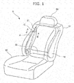
- FIG. 1 is an outline view of a seat equipped with airbag module according to the embodiment of the present invention.
- FIG. 2 is a perspective view of a seat frame of the seat equipped with airbag module according to the first embodiment of the present invention.
- FIG. 3 is a cross-sectional view taken along the line A-A of FIG. 1 and is an explanatory drawing showing a state where a stay cloth is connected to the side frame via the attachment member according to the first embodiment of the present invention.
- FIG. 4 is an explanatory drawing showing a state where a trim cover according to the first embodiment of the present invention and the stay cloths are sewn together on a breaking portion.
- FIG. 5 is a perspective view of the attachment member according to the first embodiment of the present invention.
- FIG. 6 is a plan view of the attachment member according to the first embodiment of the present invention.
- FIG. 7 is a side view of the attachment member according to the first embodiment of the present invention.
- FIG. 8 is a bottom view of the attachment member according to the first embodiment of the present invention.
- FIG. 9 is a plan view showing a state where an attachment portion of the stay cloth is held by the attachment member according to the first embodiment of the present invention.
- FIG. 10 is a bottom view showing a state where the attachment portion of the stay cloth is held by the attachment member according to the first embodiment of the present invention.
- FIG. 11 is a cross-sectional explanatory drawing showing a state where the stay cloth is connected to the side frame via the attachment member according to the first embodiment of the present invention.
- a front to back direction of the seat corresponds to a front to back direction viewed from an occupant seated at the seat and will be hereinafter also simply referred to as a front to back direction.
- an up to down direction corresponds to an up to down direction of the seat.
- a vehicle seat S serving as the seat equipped with airbag module according to the present embodiment is configured by a seat back S1, a seating portion S2, and a headrest S3.
- a seat frame F as shown in FIG. 2 is provided in the vehicle seat S.
- the seat frame F is configured by a seat back frame 1 serving as a frame of the seat back S1 and by a seating frame 2 serving as a frame of the seating portion S2.
- the seating frame 2 and the seat back frame 1 are connected via a reclining mechanism 3.
- a cushion and a trim cover are provided at the outer side of the seat back frame 1 and the seating frame 2, thereby configuring the seat back S1 and the seating portion S2.
- the seat back S1 mainly includes: the seat back frame 1; cushion pads 5, 5a which are mounted on the seat back frame 1; a trim cover 4 which covers the seat back frame 1 and the cushion pads 5, 5a; and stay cloths 31, 32, one end each of which is sewn to a breaking portion 40 of the trim cover 4.
- the seat back frame 1 is formed into a frame shape by side frames 10 which are arranged to be separated at right and left sides in a seat width direction and to extend in the up to down direction, an upper frame 21 which connects upper ends of these side frames 10, and a lower frame 22 which connects lower ends of the side frames 10.
- the seat back frame 1 corresponds to a frame member in the claims.
- Right and left side portions of the seat back frame 1 in the seat width direction where the side frames 10 are arranged correspond to side portions in the claims.
- Pillar supporting portions 23 are provided at the upper frame 21, and a headrest frame (not shown) is provided at the pillar supporting portions 23.
- a cushion material is provided at the outer side of the headrest frame, thereby configuring the headrest S3.
- the side frame 10 is formed of a substantially plate-shaped body which is curved so that a lower portion is wider than an upper portion.
- the side frame 10 includes a substantially flat plate-shaped side plate 11, a front rim 12 which is formed by folding a front end of the side plate 11 inward into a U-shape, and a rear rim 13 which is formed by bending and curving a rear end of the side plate 11 inward into an L-shape.
- Locking portions 15 provided with locking holes to which ends of each of bridging members 25 formed of S springs for supporting an occupant from behind and serving as a pair of occupant supporting members are respectively locked, and a pair of attachment holes 16 each for attaching an attachment member 50 are provided in the side frame 10.
- the attachment hole 16 is a substantially rectangular hole which is long in the up to down direction, and it is provided in the side plate 11 so as to be located adjacent to the front rim 12 while extending along the inclination of the front rim 12.
- the attachment hole 16 is formed in a position at the side frame 10, which is different from the position of a shaft portion of a bolt 18 for attaching an airbag module 6.
- the application of the attachment member 50 avoids the necessity of supporting the stay cloth 32 by the shaft portion of the bolt 18 and the necessity of directly perforating the stay cloth 32 itself; therefore, durability of a connected portion between the stay cloth 32 and the side frame 10 can be enhanced.
- the position in which the airbag module 6 is attached to the side frame 10 by the bolt 18 is different from the position in which the stay cloth 32 is connected to the side frame 10 by the attachment member 50; therefore, the attachment structure can be simplified, and in addition, attaching of the airbag module 6 to the side frame 10 is not affected by the connection structure of the stay cloth 32 to the side frame 10.
- the attachment hole 16 for attaching the inner-side stay cloth 32 is provided only in the position adjacent to the front rim 12 of the side frame 10.
- the attachment hole 16 for attaching the outer-side stay cloth 31 may be additionally provided in a position adjacent to the rear rim 13.
- a pair of attachment holes 16 is provided so that the attachment holes 16 are positioned close to upper and lower ends, respectively, of the side plate 11, and the attachment holes 16 are formed above and below the locking portions 15, respectively, so that the locking portions 15 of the bridging members 25 are arranged between the attachment holes 16.
- the attachment hole 16 is arranged so as not to be horizontal with respect to the locking portion 15 and is formed in a position different from the position of the locking portion 15 in the up to down direction.
- a front-to-rear small width portion of the side frame 10, the width of which is smaller than the width of a front-to-rear large width portion at the lower side of the side frame 10 has rigidity lower than rigidity of the front-to-rear large width portion; however, the upper frame 21 is attached so as to be located adjacent to the attachment hole 16 at the upper side. Therefore, the rigidity of the front-to-rear small width portion is compensated.
- the airbag module 6 is fixed to an outer surface of the side frame 10 in the seat width direction.
- the airbag module 6 of the present embodiment is configured by a case-less airbag module which does not include a module case. As shown in FIG. 3 , the airbag module 6 is provided with an inflator 6a, a folded airbag 6b, a retainer 6c which holds the inflator 6a, and a wrapping material 6d which wraps the airbag 6b.
- An outer peripheral portion of the inflator 6a is fixed to the retainer 6c and the side frame 10 by the bolt 18 that is provided in a standing manner to extend toward the inner side of the vehicle seat S.
- the inflator 6a may be fixed to the side frame 10 by an inflator attaching member other than a bolt.
- the inflator 6a is arranged within the airbag 6b, and the airbag 6b is configured to be deployed toward the front side of the vehicle seat S by gas discharged from the inflator 6a.
- the airbag 6b is held in a folded state by the wrapping material 6d formed of a fabric bag or the like.
- This wrapping material 6d is configured to easily break when the airbag 6b is deployed.
- the airbag module 6 is configured by a case-less airbag module but not limited thereto, and it may be configured to include a module case.
- an opening 8 for retracting the airbag module 6 is formed in the cushion pad 5, and a space 7 is formed by this opening 8.
- the trim cover 4 is formed of a publicly known material. As shown in FIG. 3 and FIG. 4 , a front gusset portion 41 which covers from the center of a seat surface to bank faces on the right and left and a side gusset portion 42 which extends from a peripheral side surface to a back surface are sewn to each other, and a rear gusset portion (not shown) is further sewn to an end of the side gusset portion 42, which is located on the opposite side of the front gusset portion 41; thereby, the trim cover 4 is sewn into a pouched shape.
- the breaking portion 40 is formed on a bulging apex on a bank portion defined between the front gusset portion 41 and the side gusset portion 42. Ends of the front gusset portion 41 and the side gusset portion 42 are sewn to each other so that the breaking portion 40 can keep the strength endurable against normal use and break by a tensile force generated by an expansion of the airbag while.
- the stay cloths 31, 32 are sewn together on the breaking portion 40.
- the stay cloth 32 formed of a fabric material with low stretching properties functions to transmit stress generated by the expansion of the airbag to the breaking portion 40.
- the stay cloths 31, 32 each corresponding to a guide member in the claims are members which guide a deployment direction of the airbag module 6.
- the stay cloth 32 is formed by a substantially rectangular fabric.
- Plural attachment portions 36 for attaching trim plates 37 each protruded into a rectangular shape are respectively provided at both ends of a side 35 facing the breaking portion 40.
- the trim plate 37 is a rectangular plate body made of a rigid resin.
- the trim plate 37 is used to maintain the shape of an end of the attachment portion 36 of the stay cloth 32.
- the trim plate 37 is fixed to the end of the stay cloth 32; therefore, workability in inserting the end of the stay cloth 32 into a holding space 59 is increased.
- the trim plate 37 corresponds to a fixing member in the claims.
- the holding space 59 functions to house the trim plate 37 sewn to the end of the stay cloth 32 and corresponds to a housing portion in the claims.
- the trim plate 37 is fixed to the attachment portion 36 of the stay cloth 32, but not limited thereto.
- a portion obtained such that the end of the attachment portion 36 of the stay cloth 32 is folded multiple times to be sewn, such that the end of the attachment portion 36 is rolled up multiple times to be sewn, or such that the end of the attachment portion 36 is rolled up to be sewn and subsequently squashed in one direction may be inserted into the holding space 59 of the attachment member 50.
- the stay cloth 32 is pulled from the breaking portion 40 into the space 7.
- the trim plate 37 fixed to the attachment portion 36 of the stay cloth 32 is locked via the attachment member 50 to the attachment hole 16 of the side frame 10.
- a locking hook 33 is sewn to the other end of the stay cloth 31 so as to be fixed thereto.
- the stay cloth 31 is pulled into a space defined between a cushion pad 5a, which is arranged at the rear side of the airbag module 6, and the airbag module 6, and the locking hook 33 is locked to the rear rim 13 of the side frame 10.
- the trim plate 37 is sewn to the end of the stay cloth 31 so as to be fixed thereto.
- the attachment hole 16 is provided adjacent to the rear rim 13 of the side frame 10; and likewise for the case of the inner-side stay cloth 32, the stay cloth 31 is fixed via the attachment member 50 to this attachment hole 16.
- the structure for attaching the stay cloth 31 via the attachment member 50 to the side frame 10 is similar to the structure for attaching the stay cloth 32 except in that the stay cloth 31 is attached reversely with respect to the stay cloth 32 in the front to back direction of the seat and therefore the description thereof will be omitted.
- the attachment member 50 is integrally molded with a rigid resin. As shown in FIG. 5 and FIG. 7 , the attachment member 50 is shaped so that a peripheral area of one side of a hollow cuboid is cut out.
- the attachment member 50 includes: a holding portion 51 which corresponds to a main body in the claims; and a plate-shaped flange portion 52 which is extended in all directions continuously from the other side which is located opposite to the cut-out one side of the holding portion 51.
- the flange portion 52 corresponds to an extended portion in the claims.
- the holding portion 51 includes: a front wall 53; a horizontal wall 54; a rear wall 55; a horizontal wall 56; a top wall 57 extending rearward and vertically from an end portion of the front wall 53, which is located opposite to the flange portion 52; and a partition wall 58 bridged between the horizontal wall 54 and the horizontal wall 56 and provided in parallel with the front wall 53 and the rear wall 55.
- a space surrounded by the front wall 53, the horizontal wall 54, the rear wall 55, the horizontal wall 56, and the top wall 57 serves as the holding space 59 inside of which the trim plate 37 is to be locked.
- the holding space 59 is divided by the partition wall 58 into a front space 59a and a rear space 59b.
- the horizontal wall 54 is located at the upper side and the horizontal wall 56 is located at the lower side.
- the horizontal wall 54 is located at the lower side and the horizontal wall 56 is located at the upper side.
- the front wall 53 is extended so as to stand substantially vertically from the flange portion 52 described below (so as to be inclined at an angle ranging from about 85 degrees to about 90 degrees with respect to the flange portion 52).
- the front wall 53 does not need to be extended so as to stand from the flange portion 52 in a planar manner, and it may be extended with stepped portions in such a way that the thickness decreases toward the rear wall 55 by about 0.5 mm as the front wall 53 separates from the flange portion 52 by about 5 mm.
- the holding portion 51 having the front wall 53 that includes the plural stepped portions at the time of inserting the holding portion 51 into the attachment hole 16, a section of the holding portion 51, which has a small thickness and a small outer shape, is first inserted and therefore may be more easily inserted than the holding portion 51 that is formed vertically from the flange portion 52.
- the front wall 53 is in contact with an inner surface of the attachment hole 16 while being substantially vertical to the attachment hole 16. Accordingly, compared with a case where the front wall 53 is formed to be inclined to the rear wall 55, rotation of the attachment member 50 is further prevented. Therefore, the attachment member 50 can be prevented from loosening from the attachment hole 16.
- the horizontal wall 54 and the horizontal wall 56 are formed of a substantially L-shape which is obtained such that one corner of a rectangle is cut out.
- a cut-out portion 57b shaped to be cut out toward the front wall 53 is formed in the center of the top wall 57 in the up to down direction.
- the cut-out portion 57b corresponds to an opposite-side check window in the claims.
- the cut-out portion 57b is formed in this manner; thereby, the top wall 57 maintains an anti-loosening function for the trim plate 37, which will be described below, and in addition, a connected state of the trim plate 37 can be checked through the cut-out portion 57b.
- a total of lengths L1 and L2 of the top wall 57 is designed to be larger than a length L3 of the cut-out portion 57b.
- the top wall 57 is formed in this manner; therefore, the rigidity can be secured and the anti-loosening function can be improved.
- the horizontal wall 54, the horizontal wall 56, and the cut-out portion 57b of the top wall 57 totally form a substantially T-shaped opening.
- the stay cloth 32 and the trim plate 37 that are locked within the holding space 59 can be visually checked through this opening as viewed from the holding portion 51.
- a bridging portion 61 described below can be molded by a two-split mold for molding the holding portion 51 and the flange portion 52.
- the rear wall 55 is formed continuously with the horizontal wall 54 and the horizontal wall 56 that are formed in a substantially L-shape.
- a height of the rear wall 55 from the flange portion 52 is designed to be smaller than a height of the front wall 53 from the flange portion 52.
- the partition wall 58 is formed so as to have substantially the same height as the height of the rear wall 55; therefore, the front space 59a is exposed from the rear wall 55 of the attachment member 50.
- a slit 55s is formed in the center of the rear wall 55 in the up to down direction.
- This slit 55s is formed continuously with a slit 52s which is provided in the center of a rear portion of the flange portion 52.
- the rear wall 55 and the rear portion of the flange portion 52 are divided by these slits 52s, 55s into two portions with respect to the center.
- the slits 52s, 55s are formed continuously with the holding space 59 so as to communicate therewith and are used to insert the stay cloth 32 into the holding space 59. Specifically, an operator inserts the stay cloth 32 in a folded state through the slits 52s, 55s and spreads the stay cloth 32 within the holding space 59; therefore, the stay cloth 32 is inserted into the attachment member 50.
- corner portions 55a of the rear wall 55 are formed to be chamfered so that the stay cloth 32 is prevented from being damaged by rubbing against the corner portions 55a when being inserted through the slit 55s into the holding space 59, the corner portions 55a being located adjacent to a portion in which the slit 55s intersects with the holding space 59.
- the rear wall 55 and the rear portion of the flange portion 52 are separated by the slits 52s, 55s; thereby, as will be described in detail below, an end portion of the rear wall 55, which is located adjacent to the slit 55s is allowed to be deformed toward the front wall 53.
- the slit 55s corresponds to a cut in the claims.
- protrusions 60 are formed on an outer surface of the rear wall 55, which faces the rear side of the seat, so as to be located respectively at both sides between which the slit 55s is interposed.
- the protrusion 60 is formed of a substantially triangle pole including: a surface 60a which faces the flange portion 52 to form nearly a right angle with respect to the rear wall 55; and a surface 60b which is located opposite to the flange portion 52 to form a small acute angle with respect to the rear wall 55.
- the protrusion 60 corresponds to a pawl portion in the claims.
- a distance between the surface 60a and the flange portion 52 is designed to be the same as or slightly larger than a thickness of the attachment hole 16 in the side frame 10.
- the surface 60a is a surface facing the flange portion 52, and a rim of the attachment hole 16 is supported between the surface 60a and the flange portion 52; thereby, the attachment member 50 can be prevented from loosening from the attachment hole 16.
- a portion of the holding portion 51 which is located adjacent to the flange portion 52 to have a thickness between the protrusion 60 and the flange portion 52, corresponds to a portion which faces the inner surface of the attachment hole in the claims.
- the attachment member 50 is in a natural state where no force is applied.
- the protrusions 60 are in contact with the inner surface of the attachment hole 16; therefore, the insertion is inhibited.
- the rear wall 55 is separated by the slit 55s, and in addition, the protrusion 60 is formed into a substantially triangle pole. Accordingly, when the attachment member 50 is pressed into the attachment hole 16, the protrusions 60 are brought into contact with the inner surface of the attachment hole 16. Therefore, a force from the front wall 53 is applied to the rear wall 55 to deform the rear wall 55. The rear wall 55 is deformed and thereby an outer periphery of the attachment member 50 becomes the same as or smaller than the inner surface of the attachment hole 16. Consequently, the attachment member 50 can be attached to the attachment hole 16.
- the partition wall 58 and the front wall 53 are connected by the bridging portion 61 while being located at an outer end of the seat.
- the bridging portion 61 is provided as a short strip-shaped portion formed at the center in an up to down direction of the partition wall 58 and the front wall 53, and it forms a surface which is flash with the flange portion 52.
- a width of the bridging portion 61 in the up to down direction of the seat is designed to be smaller than a width of the cut-out portion provided at the center of the top wall 57. Therefore, the bridging portion 61 can be molded without using a core by the two-split mold for molding the holding portion 51 and the flange portion 52.
- the bridging portion 61 serves as an anti-loosening portion which prevents the trim plate 37 and the end of stay cloth 32 which are inserted into the holding space 59, loosening from the holding space 59. Further, rigidity is increased by the bridging portion 61 compared with a case where two through-holes 62 described below are formed to be connected.
- the top wall 57 is formed in a position so as to face the through-holes 62 described below.
- a protrusion 57a protruding toward the front space 59a is provided at an end of an inner surface of the top wall 57, the end being located adjacent to the rear wall 55.
- this protrusion 57a functions as an anti-loosening portion which prevents the trim plate 37 inserted into the front space 59a from being pulled outside the front space 59a.
- This protrusion 57a includes: a flat surface formed by a surface which is located outside the front space 59a to be continuously formed with an end of the top wall 57; and a stepped portion of a substantially L-shaped hook provided on a surface which is located adjacent to the front space 59a.
- the trim plate 37 can be inserted into the front space 59a manually. Meanwhile, when the force pulling the trim plate 37 outside the front space 59a is applied, an end of the trim plate 37 is locked by this stepped portion; thereby, the trim plate 37 can be prevented from being easily pulled outside the front space 59a.
- the flange portion 52 having a flat plate shape is provided with a contact surface 52a which makes contact with the side frame 10 and a presser surface 52b which is located on the reverse side of the contact surface 52a.
- the contact surface 52a is formed of a flat surface.
- the presser surface 52b forms a curved surface 52c which is obtained by curving a peripheral rim toward the contact surface 52a so that an end meets up with an end of the contact surface 52a.
- the flange portion 52 is formed so that a front portion at the front of the holding portion 51 is longer than a rear portion at the rear side of the holding portion 51; thereby, the stay cloth 32 can be prevented from being damaged by contact with a boundary portion between the side plate 11 and the front rim 12 of the side frame 10 at the time of assembling to the side frame 10.
- the through-holes 62 are formed in the flange portion 52 so as to extend in a direction along a penetrating direction of the attachment hole 16 in a state where the attachment member 50 is attached to the side frame 10 and which intersects with the surface of the flange portion 52.
- the through-holes 62 allow the attachment portion 36 of the stay cloth 32 housed in the front space 59a to be exposed and enable an operator to check an attached state of the attachment portion 36.
- the through-hole 62 corresponds to a check window in the claims.
- FIG. 11 is a transverse sectional view showing a state where the end of the stay cloth 32 is attached via the attachment member 50 to the side plate 11 of the side frame 10.
- the attachment member 50 is inserted into the attachment hole 16 in such a way that a portion of the flange portion 52, which formed longer is provided at the front side and that an outer end surface of the holding portion 51, which is located at the flange portion 52 is brought into contact with the inner surface of the attachment hole 16 of the side frame 10.
- the rim of the attachment hole 16, which is located at the rear side is supported by the flange portion 52 and the protrusion 60 therebetween.
- the attachment member 50 is inserted into the attachment hole 16 in this manner; therefore, an attachment position of the attachment member 50 in the up to down and front to back directions can be more easily regulated by the attachment hole 16 and a contact surface of the attachment member 50, and in addition, the stay cloth 32 may be restricted from making contact with the end of the side frame 10 depending on a pulling direction of the stay cloth 32.
- the trim plate 37 is held in the front space 59a so as to face a front surface of the partition wall 58 in a state where the trim plate 37 is sewn to the end of the stay cloth 32.
- the trim plate 37 and the end of the stay cloth 32 are in contact with an inner surface of the bridging portion 61.
- the trim plate 37 having rigidity higher than rigidity of the stay cloth 32 is fixed to the end of the stay cloth 32, and the attachment member 50 is inserted into the attachment hole 16 in a state where the trim plate 37 is held in the holding space 59. Therefore, durability of the stay cloth 32 receiving a tensile force generated by an expansion of the airbag 6b can be improved compared with a case where a hole is formed in the stay cloth 32 itself and a shaft of the side frame is inserted into the hole to fix the stay cloth 32.
- the stay cloth 32 is passed between the partition wall 58 and the top wall 57 to enter the rear space 59b and is passed through an opening of the rear space 59b, which is formed in the flange portion 52, to be introduced to the outer side of the attachment member 50.
- the flange portion 52 is arranged so that the contact surface 52a is in contact with the side plate 11.
- the presser surface 52b of the flange portion 52 is pressed by the retainer 6c in a state where the stay cloth 32 is interposed between the presser surface 52b and the retainer 6c.
- FIG. 11 shows a state where the attachment portion 36 is passed through the slits 52s, 55s to penetrate through the rear space 59b and a state where the trim plate 37 and the end of the attachment portion 36 sewn to the trim plate 37 are housed in the front space 59a.
- a connected state where the attachment portion 36 is connected to the attachment member 50 as shown in FIG. 11 is defined as a normal state.
- other connected states are defined as inappropriate states.
- one end 37a of the trim plate 37, which is covered by the attachment portion 36 is located not adjacent to the top wall 57 but adjacent to the bridging portion 61 and sewn portions 38 of the attachment portion 36, which are sewn to the trim plate 37 are located not adjacent to the partition wall 58 but adjacent to the front wall 53.
- a corner portion of the other end 37b of the attachment member 50 is located adjacent to the protrusion 57a formed at the top wall 57 and is exposed without being covered by the attachment portion 36; therefore, the corner portion of the end of the attachment member 50 easily gets stuck and engaged with the protrusion 57a.
- the sewn portions 38 of the attachment portion 36 are located not adjacent to the partition wall 58 but adjacent to the front wall 53.
- the attachment portion 36 is sewn to the trim plate 37 so as to wrap around one end 37a of the trim plate 37 in a contact manner with the front wall 53, therefore being housed with the trim plate 37 in the front space 59a.
- the attachment portion 36 is arranged and the trim plate 37 is housed in the front space 59a. Accordingly, at the time of expansion of the airbag, the trim plate 37 is moved by the attachment portion 36 that is pulled from the partition wall 58. In such case, the force can be prevented from directly applied to the sewn portions 38. Consequently, a shear force to be applied to the sewn portions 38 can be reduced and the stability of connection between the attachment portion 36 and the trim plate 37 by the sewn portions 38 can be increased.
- the through-holes 62 from which the attachment portion 36 housed in the front space 59a is exposed are formed in the flange portion 52 as described above; thereby, the connected state of the attachment member 50 with the stay cloth 32 viewed from the flange portion 52 can be checked.
- the through-holes 62 are formed in the flange portion 52 in this manner; therefore, in the normal state, the attachment portion 36 of the stay cloth 32 is exposed from the through-holes 62. Meanwhile, in an inappropriate state where the sewn portions 38 are located adjacent to the partition wall 58, the trim plate 37 is exposed from the through holes 62.
- an operator checks which is exposed from the through-holes 62, the attachment portion 36 or the trim plate 37; thereby, the operator can identify whether the connected state of the attachment member is normal or inappropriate.
- the flange portion 52 is located at the outer side of the side frame 10.
- the horizontal wall 54, the horizontal wall 56, and the cut-out portion 57b of the top wall 57 totally form the substantially T-shaped opening as described above; thereby, the connected state of the attachment member 50 with the stay cloth 32 viewed from the holding portion 51 can be checked.
- the substantially T-shaped opening is formed in this manner; thereby, as shown in FIG. 9 , the attachment portion 36 and the trim plate 37 are exposed from the opening as viewed from the holding portion 51 that is located on the opposite side of the flange portion 52.
- the trim plate 37 held in the front space 59a is exposed, particularly, from the cut-out portion 57b. Therefore, the connected state, i.e., whether the attachment portion 36 is inserted into the front space 59a to be properly oriented can be identified by checking the presence or absence of exposure of the trim plate 37 from the cut-out portion 57b.
- the holding portion 51 is located at the inner side of the side frame 10.
- the connected state of the attachment member 50 attached to one of the side frames 10 with the attachment portion 36 can be identified from the through holes 62. Substantially in the same way, the connected state of the attachment member 50 attached to the other of the side frames 10 with the attachment portion 36 can be identified from the substantially T-shaped opening. Consequently, workability in checking the connected state is increased.
- the heights of the rear wall 55 and the partition wall 58 from the flange portion 52 are designed to be smaller than the height of the front wall 53 from the flange portion 52 and therefore the front space 59a is exposed from the rear wall 55 of the attachment member 50. Accordingly, the connected state of the attachment member 50 with the stay cloth 32 viewed from the rear wall 55 can be checked. Therefore, an insertion direction of the attachment portion 36 into the front space 59a can be also checked from the rear wall 55 of the holding portion 51. Specifically, in a case where the trim plate 37 is exposed as viewed from the rear wall 55, an operator can identify by checking as viewed from the rear wall 55 that the connected state is normal. Meanwhile, in a case where the trim plate 37 is not exposed while being covered by the attachment portion 36, the operator can identify that the connected state is inappropriate.
- the rear wall 55 of the holding portion 51 is posteriorly located in the side frame 10.
- At least one of these members may have a different color from those of the other members.
- the attachment portion 36 and the attachment member 50 have different colors from each other.
- the colors greatly differing, particularly in brightness of three color elements (color phase, brightness, and intensity) are applied to the members.
- a color of black or the like having low brightness is applied to one of the member and colors of white or the like having high brightness are applied to the other members.
- the differences in color can be easily identified by the differences in contrast and connected states of the members can be easily identified.
- a fluorescent paint may be applied to at least one of the members, and the attachment member 50 may be made of a transparent resin.
- the attachment of the stay cloth 32 to the attachment member 50 is performed in the following steps.
- One of two sides of the attachment portion 36, which are vertical to the trim plate 37 is passed through the slits 52s, 55s to be inserted into the rear space 59b.
- the trim plate 37 is provide so as to face the rear wall 55 while the end of the attachment portion 36 is provided to face the front wall 53.
- the other one of the two sides of the attachment portion 36, which are vertical to the trim plate 37 is also passed through the slits 52s, 55s to be inserted into the rear space 59b; therefore, the attachment portion 36 is inserted into the rear space 59b.
- one end 37a of the trim plate 37 is inserted from a clearance between the partition wall 58 and the top wall 57 into the front space 59a and is pushed thereinto until one end 37a of the trim plate 37 is brought into contact with the bridging portion 61. Therefore, the stay cloth 32 is completely connected to the attachment member 50.
- the attachment member 50 is inserted from the outer side of the seat into the attachment hole 16 of the side frame 10, and the attachment member 50 is pushed to reach a position such that a portion on the inner surface of the attachment hole 16 extending at the rear side is made interposed between the flange portion 52 and the protrusion 60.
- the attachment member 50 when the attachment member 50 is pushed into the attachment hole 16 as described above, the protrusion 60 is brought into contact with the inner surface of the attachment hole 16 and a force from the front wall 53 is applied to the rear wall 55. Then, the rear wall 55 is deformed by the force; thereby, the holding portion 51 can be inserted into the attachment hole 16.
- the attachment member 50 is further inserted to reach a position such that the protrusion 60 is moved beyond the inner surface of the attachment hole 16, the rear wall 55 is released from its deformed state and therefore the attachment member 50 is fitted into the attachment hole 16.
- the airbag module 6 is assembled from the outer side of the seat. At this time, the airbag module is fixed by the bolt 18 in such a way that at least a portion of the flange portion 52 is pressed by the retainer 6c.
- the cushion pad 5a is arranged at the outer side of the airbag module 6 and the airbag module 6 and the cushion pad 5a are covered by the trim cover 4. Thus, the airbag module is completely assembled.
- the structure where the connected state between the stay cloth and the attachment member is checked through the through-holes as viewed from the flange portion and the structure where the connected state between the stay cloth and the attachment member is checked through the cut-out portion as viewed from the holding portion are described as examples in the aforementioned embodiment, but not limited thereto. That is, a structure to check the connected state is not limited to a through-hole or a cut-out portion.
- the structure may be configured, for example, so that a window made of a transparent resin is formed at least at a portion of the flange portion or the top wall. Accordingly, a connected portion between the stay cloth and the attachment member is exposed from the window and therefore the connected state of these members may be checked.
- FIG. 12 is a perspective view of the seat frame of the seat equipped with airbag module according to the second embodiment of the present invention.
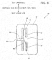
- FIG. 13 is a perspective view of the attachment member according to the second embodiment of the present invention.
- FIG. 14 is a plan view of the attachment member according to the second embodiment of the present invention.
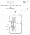
- FIG. 15 is a bottom view of the attachment member according to the second embodiment of the present invention.
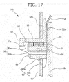
- FIG. 16 is a cross-sectional explanatory drawing showing a state where the stay cloth is connected to the side frame via the attachment member according to the second embodiment of the present invention.
- FIG. 17 is a cross-sectional explanatory drawing showing a state where the stay cloth is connected to the side frame via the attachment member according to the second embodiment of the present invention, illustrating a modified example of how to attach the stay cloth to the attachment member.
- the attachment hole 16 is a vertically-long substantially rectangular hole including two pairs of chamfered corner portions, each pair having a rear corner portion 16a and a front corner portion 16b that are provided in the front to back direction of the seat.
- the attachment hole 16 is provided in the side plate 11 so as to be located adjacent to the front rim 12 while extending along the inclination of the front rim 12.
- a length of the long side of the attachment hole 16 is 33 mm and a length of the short side of the attachment hole 16 is 11 mm.
- a radius of curvature of the front corner portion 16b is designed to be larger than a radius of curvature of the rear corner portion 16a.
- a ratio of the radius of curvature of the front corner portion 16b to the radius of curvature of the rear corner portion 16a ranges from two to one to three to one.
- the radius of curvature of the front corner portion 16b is 2.5 mm and the radius of curvature of the rear corner portion 16a is 1 mm.
- an attachment member 50y which is to be fitted into the attachment hole 16 as described below includes: chamfered rear corner portions 50a and chamfered front corner portions 50b which are respectively formed to conform to the rear corner portion 16a and the front corner portion 16b.
- a ratio of a radius of curvature of the front corner portion 50b to a radius of curvature of the rear corner portion 50a ranges from two to one to three to one, which identical to the ratio of the radius of curvature of the front corner portion 16b to the radius of curvature of the rear corner portion 16a.
- the radius of curvature of the front corner portion 50b is 2.5 mm and the radius of curvature of the rear corner portion 50a is 1mm.
- the attachment hole 16 and the attachment member 50y described below are formed in this manner. Accordingly, when the attachment member 50y described below is being fitted into the attachment hole 16, the orientation of the attachment member 50y is restricted; therefore, a wrong assembly is prevented in advance.
- front corner portion 16b and the rear corner portion 16a function as wrong assembly preventing portions 80 for the assembly of the attachment member 50y described below to the attachment hole 16.
- the radius of curvature of the front corner portion 16b is designed to be larger than the radius of curvature of the rear corner portion 16a.
- one corner portion on the inner surface of the attachment hole 16 is formed to have a radius of curvature which is different from radii of curvature of the other corner portions, and the attachment member 50y including a portion which has a shape conforming to the attachment hole 16 so as to face the inner surface is assembled to the attachment hole 16. Therefore, the same effect as that of the present embodiment can be attained.
- corner portions on the inner surface of the attachment hole 16 have different radii of curvature, it is appropriate if the corner portions can restrict the mounting orientation of the attachment member 50y.
- the corner portions are not limited to those provided in the front to back direction of the seat and may be formed in each position in an up to down direction, an oblique direction, or the like.
- the plural attachment holes 16 having the same shape are formed in the side frame 10 in the up to down direction.
- the attachment hole 16 to which the attachment member 50y is mounted is selectable and the seat frame F is used in common; thereby, versatility can be increased.
- the attachment members 50y having the same shape can be applied.
- the rear corner portions 50a are located at a portion in which the rear wall 55 intersects with the horizontal wall 54 and at a portion in which the rear wall 55 intersects with the horizontal wall 56 and the front corner portions 50b are located at a portion in which the front wall 53 intersects with the horizontal wall 54 and at a portion in which the front wall 53 intersects with the horizontal wall 56.
- These rear corner portions 50a and these front corner portions 50b are formed so that the radius of curvature of the front corner portion 50b is larger than the radius of curvature of the rear corner portion 50a as described above, thereby configuring wrong assembly preventing portions 81 relative to the inner surface of the attachment hole 16.
- the front corner portion 50b corresponds to one facing corner portion in the claims and the rear corner portion 50a corresponds to the other facing corner portion in the claims.
- the rear corner portion 50a and the front corner portion 50b are formed in this manner; thereby, the stability of attachment of the attachment member 50y to the attachment hole 16 is held.
- a large bending moment about on a portion at which the inner surface of the attachment hole 16 is supported by the protrusion 60 and the flange portion 52 therebetween is applied to the front corner portion 50a of the front wall 53 provided at a position distant from the portion.
- An increase of this bending moment causes an increase of stress on the front corner portion 50b; however, the front corner portion 50b is formed to have the radius of curvature larger than the radius of curvature of the rear corner portion 50a as described above. Accordingly, stress concentration can be reduced. Therefore, the attachment member 50y can be prevented from being deformed by the increase of stress. Consequently, the attachment member 50y can be stably attached to the attachment hole 16.
- the rear corner portion 50a, the front corner portion 50b, the rear wall 55, and the horizontal walls 54, 56 are extended so as to stand substantially vertically from the flange portion 52 (so as to be inclined at an angle ranging from about 85 degrees to about 90 degrees with respect to the flange portion 52).
- the holding portion 51 can be molded without using the core by the two-split mold.
- the flange portion 52 is not formed in an area in a direction along the rear wall 55 from a position which intersects with the protrusion 60 to a position at which the slit 55s is provided. That is, the flange portion 52 is not formed in a location adjacent to the protrusion 60.
- the flange portion 52 is formed in this manner; thereby, the attachment member 50y including the protrusions 60 can be molded without the core by the two-split mold.
- the attachment member 50y configured as described above includes the rear corner portion 50a and the front corner portion 50b that have the different radii of curvature. Therefore, the attachment member 50y can be prevented from being wrongly assembled to the attachment hole 16 without deteriorating an excellent moldability due to the two-split mold.
- FIG. 16 is a transverse sectional view showing a state where the end of the stay cloth 32 is attached via the attachment member 50y to the side plate 11 of the side frame 10.
- the trim plate 37 is attached so as to face an inner surface of the front wall 53.
- the stay cloth 32 is folded along with the width of the trim plate 37. Therefore, the trim plate 37 may be interposed between the stay cloth 32 in the front space 59a so that both surfaces of the trim plate 37 are in contact with the stay cloth 32. At this time, the stay cloth 32 makes contact with the inner surface of the front wall 53.
- a substantially entire surface of the presser surface 52b is pressed by the retainer 6c toward the side plate 11, but not limited thereto. At least a portion of the presser surface 52b may be pressed by the retainer 6c.
- the presser surface 52b is pressed by the retainer 6c.
- the presser surface 52b may be pressed by the inflator 6a or the airbag 6b.
- the presser surface 52b does not receive a pressing force from the airbag 6b in general use; however, when the airbag 6b expands, the presser surface 52b is pressed toward the side plate 11.
- the presser surface 52b may be pressed by the module case.
- a special member for pressing the presser surface 52b may be provided.
- the attachment of the stay cloth 32 to the attachment member 50y is performed in the following steps.
- One of two sides of the attachment portion 36, which are vertical to the trim plate 37 is passed through the slit 55s to be inserted into the rear space 59b.
- the trim plate 37 is provide so as to face the rear wall 55 while the end portion of the attachment portion 36 is provided to face the front wall 53.
- the other one of the two sides of the attachment portion 36, which are vertical to the trim plate 37 is also passed through the slit 55s to be inserted into the rear space 59b; therefore, the attachment portion 36 is inserted into the rear space 59b.
- the trim plate 37 is reversed by 180 degrees and the end of the attachment portion 36 is folded toward the front space 59a. Then, the trim plate 37 is inserted from the clearance between the partition wall 58 and the top wall 57 into the front space 59a and is pushed thereinto until the end of the trim plate 37 is brought into contact with the bridging portion 61. Therefore, the stay cloth 32 is completely connected to the attachment member 50y.
- the attachment member 50y is inserted from the outer side of the seat into the attachment hole 16 of the side frame 10, and the attachment member 50y is pushed to reach a position such that the inner surface of the attachment hole 16 extending at the rear side is made interposed between the flange portion 52 and the protrusion 60.
- the attachment member 50y when the attachment member 50y is pushed into the attachment hole 16 as described above, the protrusion 60 is brought into contact with the inner surface of the attachment hole 16 and a force from the front wall 53 is applied to the rear wall 55. Then, the rear wall 55 is deformed by the force; thereby, the holding portion 51 can be inserted into the attachment hole 16.
- the attachment member 50y is further inserted to a position such that the protrusion 60 is moved beyond the inner surface of the attachment hole 16, the rear wall 55 is released from its deformed state and therefore the attachment member 50y is fitted into the attachment hole 16.
- the airbag module 6 is assembled from the outer side of the seat. At this time, the airbag module is fixed by the bolt 18 in such a way that at least a portion of the flange portion 52 is pressed by the retainer 6c.
- the cushion pad 5a is arranged at the outer side of the airbag module 6 and the airbag module 6 and the cushion pad 5a are covered by the trim cover 4. Thus, the airbag module is completely assembled.
- the corner portions having the different radii of curvature are formed at the attachment member and the corner portions having the different radii of curvature are formed on the inner surface of the attachment hole into which the attachment member is fitted; thereby, the attachment member and the attachment hole are prevented from being wrongly assembled to each other.
- a structure in which the attachment member is fittable into the attachment hole only when being oriented in one direction may be applied, but not limited thereto.
- a portion of the attachment member is formed to have a protrusion in a predetermined cross-section and one location of the inner surface of the attachment hole may be formed to fit to the predetermined cross-sectional protrusion when the attachment hole is expanded in cross-section.
- the attachment member and the attachment hole may be fitted to each other.
- a portion of the attachment member is recessed in a predetermined cross-section and a protrusion having a cross-section fittable to the predetermined cross-sectional recessed shape may be formed at one location of the attachment hole.
- the attachment member and the attachment hole may be fitted to each other.
- vehicle seat corresponds to the seat equipped with airbag module of the present invention and includes the attachment member for attaching the guide member according to the present embodiment to the side frame.
- FIG. 18 is a perspective view of the seat frame of the seat equipped with airbag module according to the third embodiment of the present invention.
- FIG. 19 is a cross-sectional view taken along the line A-A of FIG. 1 of the seat equipped with airbag module according to the third embodiment and is an explanatory drawing showing a state where the stay cloth is connected to the side frame via the attachment member according to the third embodiment of the present invention.
- FIG 20 is an explanatory drawing showing a state where the trim cover according to the third embodiment of the present invention and the stay cloths are sewn together on the breaking portion.
- FIG. 21 is a perspective view of the attachment member according to the third embodiment of the present invention.
- FIG. 22 is a bottom view of the attachment member according to the third embodiment of the present invention.
- FIG. 23 is a perspective view showing a state where the stay cloth is attached to the attachment member according to the third embodiment of the present invention in a manner to be folded and subsequently separated into two portions to be sewn up.
- FIG. 24 is a bottom view of the attachment member according to a first modified example of the present invention.
- FIG. 25 is a perspective view showing a state where the stay cloth is attached to the attachment member according to a reference example in a manner to be folded and, subsequently, to be sewn up in an overlapping state.
- FIG. 26 is an explanatory drawing showing a state where the stay cloth is attached to the attachment member according to a second modified example of the present invention so as to be separated into two portions while being extended at the front side and the rear side.
- the seat back S1 mainly includes the side plates 10, and the strip-shaped stay cloth 31 and a stay cloth 32y, one end of which is sewn to the breaking portion 40 of the trim cover 4.
- trim cover 4 corresponds to a surface material in the claims and the stay cloth 32y corresponds to a strip-shaped member or the guide member in the claims.
- the locking portions 15 provided with the locking holes to which ends of each of a pair of bridging members 25 formed of S springs for supporting an occupant from behind are respectively locked, and a pair of attachment holes 16y each for attaching an attachment member 50y are provided at the side frames 10 that configure a seat frame F1.
- the attachment hole 16y is a substantially rectangular hole which is long in the up to down direction, and it is provided to extend along the inclination of the front rim 12.
- the attachment hole 16y is formed so as to be provided in a position which is substantially at the center in a height direction, which is lower than the bolt 18 described below, which is located adjacent to the front rim 12 of the side plate 11 in the front to back direction, and which is located at the front side of the bolt 18 described below.
- the attachment hole 16y is formed in such a position; thereby, the position of the attachment member 50y to be fitted into the attachment hole 16y is determined.
- the stay cloth 32y separated into two portions extending forward from the attachment member 50y that is shown in FIG. 19 and described below can be prevented from interfering with the bolt 18.
- a length of the long side of the attachment hole 16y is 33 mm and a length of the short side of the attachment hole 16y is 11 mm.
- the structure where the attachment hole 16y for attaching the inner-side stay cloth 32y is formed only in one location adjacent to the front rim 12 of the side frame 10 and the attachment member 50y is attached to this attachment hole is applied in the present embodiment; however, the present invention is not limited to this embodiment.
- both the inner-side stay cloth 32y and the outer-side stay cloth 31 may be attached to the side frame 10 by using the attachment members 50y. In such case, it is only necessary to also provide the attachment hole 16y for attaching the outer-side stay cloth 31 in a location adjacent to the rear rim 13.
- the pair of attachment holes 16y is provided substantially at the center in the height direction of the side plates 11 as described above; however, the present invention is not limited to this embodiment.
- plural pairs of attachment holes 16y may be provided in the height direction.
- the attachment hole 16y may be formed in the side frame 10 only at one side at which the airbag module 6 is provided.
- the seat back frame 1 can be used in common, for example, for a passenger seat and a driver seat in which the airbag modules 6 are attached at different sides from each other, therefore increasing versatility.
- the stay cloth 32y is formed by a fabric which is separated from the attachment member 50y into two portions in the up to down direction. As shown in FIG. 19 , the stay cloth 32y is pulled from the breaking portion 40 into the space 7. The stay cloth 32y is locked via the attachment member 50y to the attachment hole 16y of the side frame 10. Further, as shown in FIG. 19 , the locking hook 33 is sewn to the end of the stay cloth 31 so as to be fixed thereto. The stay cloth 31 is pulled into the space defined between the cushion pad 5a that is arranged at the rear side of the airbag module 6 and the airbag module 6, and the locking hook 33 is locked to the rear rim 13 of the side frame 10.
- outer-side stay cloth 31 may be attached to the side frame 10 by using the attachment member 50y.
- the attachment member 50y is integrally molded with a rigid resin. As shown in FIG. 21 to FIG. 23 , the attachment member 50y includes: a substantially cuboid holding portion 51y having a front through-hole 59c and a rear through-hole 59d which extend substantially in parallel with each other; and the plate-shaped flange portion 52 extended in all directions on a surface which is substantially vertical to the front through-hole 59c and the rear through-hole 59d in the holding portion 51y.
- the holding portion 51y corresponds to the main body in the claims and includes the front wall 53, the horizontal wall 54, the rear wall 55, the horizontal wall 56, and the partition wall 58 that is bridged between the horizontal wall 54 and the horizontal wall 56 to extend in parallel with the front wall 53 and the rear wall 55 and that corresponds to a partition portion in the claims.
- the front through-hole 59c or the rear through-hole 59d corresponding to other through-hole in the claims and having a substantially rectangular cross-section is formed so as to be surrounded by the front wall 53, the horizontal wall 54, the rear wall 55, the horizontal wall 56, and the partition wall 58.
- the front through-hole 59c and the rear through-hole 59d separated from each other by the partition wall 58 allow penetration of the stay cloth 32y into the attachment member 50y.
- the rear wall 55 is formed continuously with the horizontal wall 54 and the horizontal wall 56.
- the height of the rear wall 55 from the flange portion 52 is designed to be substantially the same as the height of the front wall 53 or the partition wall 58 from the flange portion 52.
- Two rims of the front wall 53, which are located at the partition wall 58 and two rims of the rear wall 55, which are located at the partition wall 58 are formed to have a chamfered shape on the partition wall 58.
- the partition wall 58 is formed in this manner; thereby, the attachment member 50y can appropriately hold the stay cloth 32y that is in contact with the rims of the partition wall 58.
- a width of the partition wall 58 in the front to back direction of the seat is designed to be larger than a width of the front through-hole 59c or the rear through-hole 59d in the front to back direction of the seat.
- the front through-hole 59c and the rear through-hole 59d that are formed in the holding portion 51y are formed in a direction which penetrates from the holding portion 51y to the flange portion 52 and intersects with the surface of the flange portion 52.
- the stay cloth 32y is passed from the flange portion 52 through one of the front through-hole 59c and the rear through-hole 59d. Thereafter, the stay cloth 32y located at the reverse side of the flange portion 52 is folded via the partition wall 58 and is passed through the other of the front through-hole 59c and the rear through-hole 59d to be extended out from the flange portion 52. Then, portions of the stay cloth 32 extended out from the flange portion 52 and located adjacent to the flange portion 52 are sewn with each other by a sewn portion 39a so as to make a predetermined angle, thereafter being attached to the attachment member 50y.
- the sewn portion 39a corresponds to a connection portion in the claims.
- the stay cloth 32y is introduced from the opening of the flange portion 52 to the outer side of the attachment member 50y and is fixed to the side frame 10 while being overlaid on the partition wall 58 of the attachment member 50y.
- the durability of the stay cloth 32y receiving a tensile force due to an expansion of the airbag 6b can be increased.
- the presser surface 52b of the flange portion 52 is pressed by the retainer 6c in a state where the stay cloth 32 is interposed between the presser surface 52b and the retainer 6c.
- the stay cloth 32y is interposed between the presser surface 52b of the flange portion 52 and the retainer 6c to be in a plane contact with these members, thereby being protected without being locally in contact with other portions.
- the sewn portion 39a of the stay cloth 32y is formed so as to be positioned between the flange portion 52 and the retainer 6c, thereby being protected.
- the stay cloth 32y is passed from the flange portion 52 through one of the front through-hole 59c and the rear through-hole 59d and then is folded so as to be overlaid on the partition wall 58. Thereafter, the stay cloth 32 is passed through the other of the front through-hole 59c and the rear through-hole 59d to be extended out from the flange portion 52.
- the two separated portions of the stay cloth 32y are respectively sewn to the front gusset portion 41 and the side gusset portion 42 so as to be positioned at the front side of the seat, thereby forming an upper breaking portion 40a and a lower breaking portion 40b.
- the stay cloth 31 to which the locking hook 33 is sewn is also sewn to the front gusset portion 41 and the side gusset portion 42 so as to be positioned at the rear side of the seat.
- the upper breaking portion 40a is provided at a position adjacent to a height of the chest of an occupant and that the lower breaking portion 40b is provided at a position adjacent to a height of the waist of the occupant.
- the trim cover 4 and the stay cloth 32y are integrally sewn; thereafter, the holding portion 51y of the attachment member 50y attached to the stay cloth 32y is inserted from the outer side of the seat into the attachment hole 16y of the side frame 10 and the attachment member 50y is pushed to reach a position such that a portion on the inner surface of the attachment hole 16y extending at the rear side is made interposed between the flange portion 52 and the protrusion 60.
- the attachment member 50y when the attachment member 50y is pushed into the attachment hole 16y as described above, the protrusion 60 is brought into contact with the inner surface of the attachment hole 16y and a force from the front wall 53 is applied to the rear wall 55. Then, the rear wall 55 is deformed by the force; thereby, the holding portion 51y can be inserted into the attachment hole 16y.
- the attachment member 50y is further inserted to a position such that the protrusion 60 is moved beyond the inner surface of the attachment hole 16y, the rear wall 55 is released from its deformed state and therefore the attachment member 50y is fitted into the attachment hole 16y.
- the stay cloths 31, 32y are attached to the side frame 10 by the attachment member 50y and the locking hook 33.
- the airbag module 6 is assembled from the outer side of the seat, and the cushion pad 5a is arranged at the outer side of the airbag module 6 and the airbag module 6 and the cushion pad 5a are covered by the trim cover 4. Thus, the airbag module is completely assembled.
- a rear surface of the front wall 53 which configures the front through-hole 59c has a chamfered corner portion formed at the flange portion 52 and a radius of curvature of the chamfered corner portion may be designed to increase toward the upper side of the seat.
- a rear surface of the partition wall 58 which configures the rear through-hole 59d has a chamfered corner portion formed at the flange portion 52 and a radius of curvature of the chamfered corner portion may be designed to increase toward the lower side of the seat.
- the front through-hole 59c and the rear through-hole 59d of the attachment member 50y according to the aforementioned embodiment are described as through-holes each having a substantially rectangular cross-section; however, the present invention is not limited to a structure including the attachment member 50y according to this embodiment.
- the front through-hole 59c and the rear through-hole 59d may have rims of a curved-surface shape or an inclination so that the stay cloth 32y can be easily sewn while being separated into two portions at a predetermined angle.
- an attachment member 70 is configured to include: a front through-hole 70a formed by a curved wall surface of the front wall 53, which is a front rim surface of the front through-hole 70a; and a rear through-hole 70b formed by a curved wall surface of the partition wall 58, which is a front rim surface of the rear through-hole 70b.
- the front rim surface of the front through-hole 70a is formed into a curved shape to be curved forward from the center to both ends in the up to down direction and the front rim surface of the rear through-hole 70b is formed into a curved shape to be curved rearward from the center to both ends in the up to down direction.
- the front through-hole 70a and the rear through-hole 70b are formed in this manner; thereby, a position of the stay cloth 32y inserted into these through-holes is changed in the up to down direction. Accordingly, the stay cloth 32y is extended from the flange portion 52 along the front rim surface of the front through-hole 70a while being smoothly separated into two portions. Consequently, the stay cloth 32y can be easily sewn while being separated into two portions at a predetermined angle.
- the front through-hole 59c, 70a or the rear through-hole 59d, 70d may be formed so as to widen in a direction from the holding portion 51y to the flange portion 52.
- the stay cloth 32y is extended from the flange portion 52 along the rim surface of the front through-hole 59c, 70a or the rear through-hole 59d, 70d while being smoothly separated into two portions.
- stay cloth 32y separated into two portions extends forward from the attachment member 50y, 70 (extends at the inner side of the airbag module 6) as described in the aforementioned embodiments, but not limited thereto.
- the stay cloth 32y extending rearward from the attachment member 50y, 70 (extending at the outer side of the airbag module 6) may be extended so as to be separated into two portions.
- the attachment members 50y are attached at the front and rear sides without using the locking hook 33; thereby, the stay cloths 31, 32y at the both front and rear sides of the attachment members 50y may be extended so as to be separated into two portions.
- the stay cloth 32y is sewn by the sewn portion 39a into two portions to be sewn by the upper braking portion 40a and the lower breaking portion 40b to the trim cover 4.
- an embodiment where portions of the stay cloth 32y extended from the front through-hole 59c and the rear through-hole 59d are sewn by a sewn portion 39b so as to overlap each other in the thickness direction may be proposed.
- the trim cover 4 can break more easily at the timing of expansion of the airbag 6b. That is, the two portions of the stay cloth 32y are sewn to the breaking portion 40 of the trim cover 4, thereby being stably sewn to the trim cover 4.
- an upper limit of a load applied to the breaking portion 40 can be increased to therefore easily break the trim cover 4.
- the stay cloth 32y extends in only one direction, forward or rearward from the attachment member 50y, 70 while being separated into two portions, but not limited thereto.
- a strip-shaped stay cloth 82 is passed through the front through-hole 59c and the rear through-hole 59d and both ends of the stay cloth 82 are sewn to the front gusset portion 41 and the side gusset portion 42 on the breaking portion 40, and the attachment member 50y may be attached to the side plate 11 so that the airbag module 6 is surrounded by the stay cloth 82 in the front to back direction. That is, the stay cloth 82 is separated into two portions from the attachment member 50y to extend forward and rearward, therefore being extended in two directions, i.e. at the inner and outer sides of the airbag module 6.
- one of the two separated portions of the stay cloth 82 which extends at the inner side of the airbag module 6 in the seat width direction corresponds to an inner-side guide member in the claims.
- the other of the two separated portions of the stay cloth 82 which extends at the outer side of the airbag module 6 in the seat width direction corresponds to an outer-side guide member in the claims.
- the stay cloth 82 is attached by the attachment member 50y; thereby, the front and rear sides of the airbag module 6 can be covered without requiring two sheets of stay cloths or without requiring an additional attachment member 50y or an additional locking hook 33.
- the attachment member according to the present invention is an attachment member for attaching a guide member, which guides a deployment direction of an airbag module, to a frame member, the attachment member including a main body which has a housing portion for housing an end side of the guide member and which is inserted into an attachment hole to be fitted into the attachment hole that is formed in the frame member, wherein check window is formed in the main body, the check window allowing the end side of the guide member in the housing portion to be exposed in a penetrating direction of the attachment hole in a state where the guide member is attached to the frame member.
- the attachment hole is formed in a side frame of a seat equipped with airbag module, and a wrong assembly preventing portion which prevents the attachment member from being wrongly attached to the attachment hole is provided.
- the wrong assembly preventing portion may be formed at least at a portion which faces an inner surface of the attachment hole.
- a seat equipped with an airbag module which retracts an airbag includes: the attachment member; the side frame that extends along a side portion of the seat equipped with airbag module; the airbag module that is attached to the side frame; and the guide member for guiding the deployment direction of the airbag module, and the wrong assembly preventing portion may be formed at least at a portion where the inner surface of the attachment hole and the attachment member face each other.
- the seat includes a cushion pad arranged on the frame member and a surface material covering the frame member and the cushion pad, and the guide member may be separated from the main body into two portions to be attached to the surface material.
- the attachment member is located at the outer side in the seat width direction to be covered by the airbag module, that the main body includes other through-holes, that the guide member is passed through the foregoing other through-holes to be folded back and the guide member includes a connection portion for connecting the folded portions, that the guide member is separated into two portions not by the connecting portion but by a portion located adjacent to the surface material, and that the connection portion is positioned at the outer side in the seat width direction so as to overlap the attachment member in a state where the attachment member is attached to the frame member.
- connection portion in a state where the attachment member is attached to the frame member, the connection portion is positioned at the outer side in the seat width direction so as to overlap the attachment member and is arranged between the attachment member and the airbag module; thereby, the connection portion can be protected.
- a plate-shaped flange portion which is to be in contact with the frame member is formed at the attachment member and that the connection portion is positioned at the outer side in the seat width direction so as to overlap the flange portion in a state where the attachment member is attached to the frame member.
- connection portion in a state where the attachment member is attached to the frame member, the connection portion is positioned at the outer side in the seat width direction so as to overlap the flange portion and is arranged between the flange portion and the airbag module; thereby the connection portion can be protected.
- the guide member is configured by one sheet of strip-shaped member.
- the guide member is configured by one sheet of strip-shaped member; thereby, the number of components can be reduced.
- the attachment member includes a partition portion by which the foregoing other through-holes are separated from each other, and that the guide member is passed through one and the other of the foregoing other through-holes separated by the partition portion and is overlaid on the partition portion.
- the guide member is overlaid on the partition portion; thereby, the guide member can be attached to the attachment member without using a separate member.
- one of the two portions of the guide member is provided as an inner-side guide member which passes through the inner side of the airbag module in the seat width direction while the other of the two portions is provided as an outer-side guide member which passes through the outer side of the airbag module in the seat width direction, that the airbag module is assembled at the outer side of the attachment member in the seat width direction, and that the attachment member is interposed between the airbag module and the frame member.
- one of the two portions of the guide member is provided as the inner-side guide member that passes through the inner side of the airbag module in the seat width direction while the other of the two portions is provided as the outer-side guide member that passes through the outer side of the airbag module in the seat width direction; thereby, the inner-side guide member and the outer-side guide member can be attached by the single attachment member.
Landscapes
- Engineering & Computer Science (AREA)
- Mechanical Engineering (AREA)
- Aviation & Aerospace Engineering (AREA)
- Transportation (AREA)
- Air Bags (AREA)
- Seats For Vehicles (AREA)
Abstract
Description
- The present invention relates to an attachment member and a seat equipped with airbag module, and it pertains to an attachment member for attaching a guide member for guiding a deployment direction of an airbag and a seat equipped with airbag module including the attachment member.
- Conventionally, a seat in which an airbag module is attached to a side frame of a seat back frame has been proposed as a seat equipped with airbag module. For example, ends of a trim cover (surface material) are sewn together with respective one ends of two stay cloths (which will be hereinafter referred to as guide members) to form a breaking portion of the trim cover. The two stay cloths are pulled from the breaking portion into the inside of the trim cover to wrap the airbag module; thereby, a seat back including this airbag module is entirely covered by the trim cover (for example, see
Patent document 1,Patent document 2, or Patent document 3). - In particular,
Patent document 1 discloses the technique to attach an attachment member attached to the end of the stay cloth to a rim of the side frame. Specifically, a groove to be connected with the end of the stay cloth and a groove to be locked to a front rim of the side frame are formed in the attachment member, and these two grooves are formed so as to extend in parallel with each other. - According to the invention of
Patent document 1, the stay cloths allow an expansion pressure of the airbag to be effectively concentrated on a sewn portion that serves as the breaking portion of the trim cover and high deployment performance of the airbag can be maintained. In addition, the stay cloths can be easily attached by using the attachment member. - Further, two listing wires disclosed in
Patent document 2 are located on the opposite side of the airbag module of the side frame so as to be entwined with each other to form a wire puzzle shape. The ends of the two stay cloths pulled from the breaking portion to both sides of the airbag module are extended to the two listing wires so that the stay cloths wrap the airbag module, thereafter being attached respectively to the listing wires. - According to the invention of
Patent document 2, the airbag module is directly wrapped by the stay cloths and the stay cloths can be surely pulled and locked by the listing wires with their respective ends at which the stay cloths are provided. The expansion pressure of the airbag can be effectively concentrated by the stay cloths on the sewn portion that serves as the breaking portion of the trim cover. As a result, the high deployment performance of the airbag can be attained. - However, in the invention of
Patent document 2, the listing wires are provided so as to be entwined with each other to form a wire puzzle shape; therefore, the listing wires are configured in a complicated manner and an attaching process is complicated. In addition, the listing wires are required to attach the stay cloths to the side frame, resulting in an increase of the size of an area surrounding the side frame; therefore, a more compact structure has been required. - Accordingly, the inventors have proposed to fix an attachment member for holding an end of a stay cloth to a side frame without using a listing wire and to easily fix the stay cloth so that an airbag module is wrapped by the stay cloth (Japanese Patent Application No.
2012-288619 - Specifically, a portion of the attachment member is fitted into a substantially rectangular attachment hole of the side frame to thereby fix the end of the stay cloth to the side frame.
- In the invention according to Japanese Patent Application No.
2012-288619 - Further,
Patent document 3 discloses the seat equipped with airbag module in which a support bar and two wires which are configured by wire rods of piano wire rods or the like are used to attach the stay cloths to the side frame. - Specifically, in order to attach the two stay cloths to the side frame, firstly, respective one ends of the two stay cloths are sewn to the surface material, and the other end of one of the two stay cloths is sewn to one of the two wires and the other end of the other of the two stay cloths is sewn to the other of the wires. Next, the wires are respectively hooked to the support bar so as to be entwined with the support bar that is fixed to the side frame.
- Furthermore, the stay cloth disclosed in
Patent document 3 is fan-shaped in a manner to spread out fanwise from a portion sewn to the wire and is formed so as to cover the airbag module. -
- PATENT DOCUMENT 1:
JP 2013-112186A - PATENT DOCUMENT 2:
JP 4543270B - PATENT DOCUMENT 3:
JP 3978741B - Here, in the technique disclosed in
Patent document 1, a process for attaching the stay cloth to the attachment member is one process which is included in a process for attaching the trim cover to the seat back frame. Therefore, it is necessary to, before completely covering the seat back frame by the trim cover, check whether the attachment member is attached to the stay cloth in a correct procedure. - As described above, in the attachment member, the groove to be locked to the front rim of the side frame and the groove to be connected with the end of the stay cloth are formed to extend in parallel with each other. In addition, the front rim of the side frame extends in an up to down direction.
- Accordingly, in a state where the attachment member is attached to the front rim of the side frame, the groove formed in the attachment member to be connected with the end of the stay cloth extends in the up to down direction. Therefore, in order to check a connected state between the stay cloth and the attachment member after attaching the attachment member to the side frame in a seat width direction, an operator needs to change his/her position to check by shifting a view in the seat width direction at the time of attaching the attachment member to the side frame to a view toward the upper or lower side relative to the attachment member, resulting in low workability.
- Further, the operation to attach the end of the stay cloth to the side frame by using the attachment member as disclosed in
Patent document 1 is performed in a manner to attach the attachment member to the side frame by pulling the stay cloth in a state where the trim cover is rolled up by the operator. - Thus, in a case where the connected state between the stay cloth and the attachment member is checked in a state where the attachment member is attached to the side frame, the trim cover needs to be rolled up. This makes the operation difficult and therefore an instant check is required. Furthermore, a clipped portion may be hidden by the trim cover; therefore, the connected state may not be easily checked.
- Further, in the invention according to Japanese Patent Application No.
2012-288619 - Furthermore, in the structure disclosed in
Patent document 3 where the two stay cloths are attached to the side frame by using the two wires, the stay cloths are sewn to the two wires, respectively, and in addition, the two wires needs to be entwined with the support bar in a state where the stay cloths are pulled. Thus, the number of components is large and workability is low. - Moreover, the stay cloth is formed to have a fan-shape. Therefore, an expansion pressure when the airbag is operated is widely applied to the sewn portion on which the fanwise spread portions of the stay cloths sewn to each other are sewn together with the surface material. Consequently, in an area of the sewn portion in the up to down direction of the seat, it is difficult to control the deployment of the airbag in such a way that the sewn portion breaks at different timing.
- The present invention is made in view of the aforementioned problems, and it is an object of the invention to provide an attachment member which allows a connected state between the attachment member and a guide member to be easily checked.
- Further, it is other objects of the present invention to provide the attachment member which allows the guide member to be easily attached and to provide a seat equipped with airbag module which prevents a wrong assembly of the attachment member and has high manufacturing efficiency.
- Furthermore, it is still another object of the present invention to provide the seat equipped with airbag module in which the guide member for guiding the deployment direction of an airbag can be easily attached to a frame member and in which loads in different positions or in different directions can be transmitted from the guide member to a surface material.
- The aforementioned problems can be solved by an attachment member for attaching a guide member, which guides a deployment direction of an airbag module, to a frame member, the attachment member including a main body which has a housing portion for housing an end side of the guide member and which is inserted into an attachment hole to be fitted into the attachment hole that is formed in the frame member, wherein a check window is formed in the main body, the check window allowing the end side of the guide member in the housing portion to be exposed in a penetrating direction of the attachment hole in a state where the guide member is attached to the frame member.
- According to the above structure, the check window that allows the end side of the guide member housed in the housing portion of the main body to be exposed in the penetrating direction of the attachment hole is formed in the main body. Therefore, the attachment member which allows a connected state between the attachment member and the guide member to be easily checked without shifting a vision after an operation to insert the main body can be provided.
- Further, it is preferable that a plate-shaped flange portion which is to be in contact with the frame member is formed at the main body, that the check window is a through-hole which penetrates through the flange portion, and that the main body includes a bridging portion that bridges over the through-hole.
- According to the above structure, the main body includes the flange portion and the bridging portion that is bridged between the through-holes formed in the flange portion. Therefore, the attachment member is stably attached to the frame member by the flange portion, and a reduction of rigidity due to the through-holes can be inhibited by the bridging portion that is bridged between the through-holes. In addition, the end side of the guide member can be prevented from loosening from the through-holes.
- Furthermore, it is preferable that a fixing member which is to be locked into the housing portion is fixed to the end side of the guide member and that at least one of the guide member, the main body, and the fixing member has a different color from colors of the others.
- According to the above structure, the fixing member is locked; thereby, the end side of the guide member can be stably housed in the housing portion, and in addition, at least one of the guide member, the main body, and the fixing member can be easily identified by the difference in color and whether an assembled state of each component is normal can be easily checked.
- Moreover, it is preferable that the guide member has a different color from a color of the main body.
- According to the above structure, a connected state between the guide member and the main body can be easily checked by the difference in color.
- In addition, it is preferable that the fixing member, the guide member, and the main body all have different colors.
- According to the above structure, the components can be individually identified and therefore their connected states are more properly checked.
- Further, it is preferable that an anti-loosening portion which prevents the fixing member from loosening from the housing portion is formed in the main body and that the anti-loosening portion is formed in a position to face the check window.
- According to the above structure, the anti-loosening portion which prevents the fixing member from loosening from the housing portion is formed in the main body, and in addition, the check window is formed in positions to face the anti-loosening portion. Therefore, the fixing member is stably housed by the anti-loosening portion and the connected state of the guide member can be surely checked from the check window.
- Furthermore, preferably, an opposite-side check window is formed in the main body so as to be located on the opposite side of the housing portion from the check window and to be opened to allow the end side of the guide member to be exposed.
- According to the above structure, the main body includes the check window and the opposite-side check window; thereby, the connected state can be checked from two sides of the check window and the opposite-side check window and it becomes much easier to do the checking operation.
- Moreover, it is preferable that an opposite-side check window is formed in the main body so as to be located on the opposite side of the housing portion from the check window and to be opened to allow the end side of the guide member to be exposed, and that the opposite-side check window is a cut-out portion which is formed in the anti-loosening portion.
- According to the above structure, the opposite-side check window is configured by the cut-out portion formed in the anti-loosening portion. Therefore, the end side of the guide member is prevented from loosening by the anti-loosening portion, and in addition, the connected state of the end side of the guide member can be checked from the opposite side of the check window.
- In addition, it is preferable that the housing portion is formed to be elongated and that a length of the anti-loosening portion in an elongation direction of the housing portion is larger than a length of the cut-out portion in the elongation direction of the housing portion.
- According to the above structure, the anti-loosening portion is configured so as to be longer in the elongation direction of the housing portion than the length of the cut-out portion in the elongation direction of the housing portion. Therefore, a function to check the connected state is secured, and in addition, the capability of prevention against loosening of the end side of the guide member can be improved.
- Further, the attachment hole is formed in a side frame of a seat equipped with airbag module, and a wrong assembly preventing portion which prevents the attachment member from being wrongly attached to the attachment hole is provided. The wrong assembly preventing portion may be formed at least at a portion which faces an inner surface of the attachment hole.
- According to the above structure, in a case where the attachment member may be attached to the attachment hole to be wrongly oriented, a portion of the attachment member, which faces the inner surface of the attachment hole interferes with the inner surface of the attachment hole and the attachment member is not fitted into the attachment hole. Therefore, a wrong assembly is prevented in advance. Consequently, the attachment member does not need to be re-assembled. As a result, the attachment member that is easily attached to the attachment hole and that can increase manufacturing efficiency of the seat can be provided.
- Furthermore, it is preferable that the main body includes a pawl portion which is to be locked to the side frame and a plurality of chamfered facing comer portions which are to face a plurality of chamfered corner portions formed at the attachment hole, that the main body has a cut which is formed so as to be communicated from an outer surface of the main body to the housing portion, that one facing corner portion of the plurality of chamfered facing corner portions is formed to have a radius of curvature which is larger than a radius of curvature of the other facing corner portion, and that the one facing corner portion is formed on the opposite of one side where the pawl portion and the cut are formed.
- According to the above structure, the facing corner portion is formed so as to have the large radius of curvature and is located at the opposite side of the one side where the pawl portion to be locked to the side frame and the cut are formed. Therefore, in a state where the attachment member is locked to the side frame by the pawl portion, stress concentration on the side opposite to the pawl portion in the attachment member can be avoided.
- Moreover, it is preferable that the main body includes an extended portion which is extended to the opposite side from the one side of the housing portion and that the extended portion is configured so that a portion at the one side is smaller than a portion at the opposite side.
- According to the above structure, in the attachment member pivoting about a portion thereof which is attached to the side frame by the pawl portion located at the one side, the extended portion is configured so that a portion at the one side is smaller than a portion at the opposite side. Therefore, a contact area of the extended portion at the one side with the side frame can be reduced and the one side of the attachment member can be easily deformed.
- In addition, a seat equipped with an airbag module which retracts an airbag includes: the attachment member; the side frame that extends along a side portion of the seat equipped with airbag module; the airbag module that is attached to the side frame; and the guide member for guiding the deployment direction of the airbag module, and the wrong assembly preventing portion may be formed at least at a portion where the inner surface of the attachment hole and the attachment member face each other.
- According to the above structure, in a case where the attachment member may be attached to the attachment hole to be wrongly oriented, a portion of the attachment member, which faces the inner surface of the attachment hole interferes with the inner surface of the attachment hole and the attachment member is not fitted into the attachment hole. Therefore, a wrong assembly is prevented in advance. Consequently, the attachment member does not need to be re-assembled without checking position of the attachment member. As a result, the seat equipped with airbag module in which the attachment member can be easily attached to the attachment hole and which has high manufacturing efficiency of the seat can be provided.
- Further, it is preferable that the attachment hole is shaped to include a plurality of chamfered corner portions, and that the wrong assembly preventing portion is configured so that at least one corner portion of the plurality of chamfered corner portions has a radius of curvature which is different from a radius of curvature of the other corner portion.
- According to the above structure, one corner portion of the plurality of corner portions can be formed by dimension setting of forming molds or by an easy processing so as to have a radius of curvature which is different from a radius of curvature of the other corner portion and a wrong assembly can be inhibited at low cost.
- Furthermore, preferably, the one corner portion and the other corner portion are arranged in a front to back direction of the seat.
- According to the above structure, in the attachment hole of the side frame, the one corner portion and the other corner portion that have the different radii of curvature are arranged in the front to back direction. Therefore, in a case where the airbags are attached to different side frames at right and left sides, for example, to a side frame of a passenger seat and a side frame of a driver seat, the attachment members are attached to the side frames in a manner to be orientated reversely in the up to down direction. Thus, the attachment member can be used in common.
- Moreover, preferably, the radius of curvature of the one corner portion that is arranged at the front side is larger than the radius of curvature of the other corner portion.
- According to the above structure, on the inner surface of the attachment hole of the side frame, the corner portion at the front side has the large radius of curvature. Therefore, stress concentration at the front side on the inner surface of the attachment hole is reduced. Consequently, supporting rigidity can be appropriately attained and attachment stability can be increased. That is, in a case where the guide member is pulled at the time of expansion of the airbag, a load can be appropriately supported by the corner portion at the front side on the inner surface of the attachment hole where stress concentration is reduced.
- Further, it is preferable that the attachment hole includes a plurality of attachment holes arranged in an up to down direction of the side frame and that the plurality of attachment holes has the same shape.
- According to the above structure, the attachment members to be attached to the plurality of attachment holes arranged in the up to down direction can be used in common.
- Furthermore, the seat includes a cushion pad arranged on the frame member and a surface material covering the frame member and the cushion pad, and the guide member may be separated from the main body into two portions to be attached to the surface material.
- According to the above structure, the guide member is separated from the main body into two portions to be attached to the surface material. Therefore, the seat equipped with airbag module can be provided in which loads in different positions or in different directions can be transmitted to the surface material by the guide member extending from the attachment member in two directions.
- According to the present invention, the attachment member which allows a connected state between the attachment member and the guide member to be easily checked without shifting a vision after an operation to insert the main body can be provided.
- Further, according to the present invention, the attachment member is stably attached to the frame member by the flange portion, and a reduction of rigidity due to the through-holes can be inhibited by the bridging portion that is bridged between the through-holes. In addition, the end side of the guide member can be prevented from loosening from the through-holes.
- Furthermore, according to the present invention, at least one of the guide member, the main body, and the fixing member can be easily identified and whether an assembled state of each component is normal can be easily checked.
- Still further, according to the present invention, a connected state between the guide member and the main body can be easily checked.
- Moreover, according to the present invention, connected states of components are more properly checked.
- In addition, according to the present invention, the end side of the guide member is stably housed in the predetermined housing portion by the anti-loosening portion and the connected state of the guide member can be surely checked from the check window.
- Further, according to the present invention, the connected state can be checked from two sides of the check window and the opposite-side check window and it becomes much easier to do the checking operation.
- Furthermore, according to the present invention, the end side of the guide member is prevented from loosening by the anti-loosening portion, and in addition, the connected state of the end side of the guide member can be checked from the opposite side of the check window.
- Still further, according to the present invention, a function to check the connected state is secured, and in addition, the capability of prevention against loosening of the end side of the guide member can be improved.
- Moreover, according to the present invention, the attachment member that is easily attached to the attachment hole and that can increase manufacturing efficiency of the seat can be provided.
- Further, according to the present invention, in a state where the attachment member is locked to the side frame by the pawl portion, stress concentration on the side opposite to the pawl portion in the attachment member can be avoided.
- Furthermore, according to the present invention, a contact area of the extended portion at the one side with the side frame can be reduced and the one side of the attachment member can be easily deformed.
- According to the present invention, the seat equipped with airbag module in which the attachment member can be easily attached to the attachment hole and which has high manufacturing efficiency of the seat can be provided.
- Further, according to the present invention, one corner portion of the plurality of corner portions can be formed by dimension setting of forming molds or by an easy processing so as to have a radius of curvature which is different from a radius of curvature of the other corner portion and a wrong assembly can be inhibited at low cost.
- Furthermore, according to the present invention, the attachment members are attached in a manner to be orientated reversely in the up to down direction, thereby being used in common.
- Still further, according to the present invention, stress concentration at the front side on the inner surface of the attachment hole is reduced; thereby, supporting rigidity can be appropriately attained and attachment stability can be increased.
- Moreover, according to the present invention, the attachment members to be attached to the plurality of attachment holes arranged in the up to down direction can be used in common.
- According to the present invention, the seat equipped with airbag module can be provided in which loads in different positions or in different directions can be transmitted to the surface material by the guide member extending from the attachment member in two directions.
-
-
FIG. 1 is an outline view of a seat equipped with airbag module according to an embodiment of the present invention; -
FIG. 2 is a perspective view of a seat frame of the seat equipped with airbag module according to a first embodiment of the present invention; -
FIG. 3 is a cross-sectional view taken along the line A-A ofFIG. 1 and is an explanatory drawing showing a state where a stay cloth is connected to a side frame via an attachment member according to the first embodiment of the present invention; -
FIG. 4 is an explanatory drawing showing a state where a trim cover according to the first embodiment of the present invention and the stay cloths are sewn together on a breaking portion; -
FIG. 5 is a perspective view of the attachment member according to the first embodiment of the present invention; -
FIG. 6 is a plan view of the attachment member according to the first embodiment of the present invention; -
FIG. 7 is a side view of the attachment member according to the first embodiment of the present invention; -
FIG. 8 is a bottom view of the attachment member according to the first embodiment of the present invention; -
FIG. 9 is a plan view showing a state where an attachment portion of the stay cloth is held by the attachment member according to the first embodiment of the present invention; -
FIG. 10 is a bottom view showing a state where the attachment portion of the stay cloth is held by the attachment member according to the first embodiment of the present invention; -
FIG. 11 is a cross-sectional explanatory drawing showing a state where the stay cloth is connected to the side frame via the attachment member according to the first embodiment of the present invention; -
FIG. 12 is a perspective view of the seat frame of the seat equipped with airbag module according to a second embodiment of the present invention; -
FIG. 13 is a perspective view of the attachment member according to the second embodiment of the present invention; -
FIG. 14 is a plan view of the attachment member according to the second embodiment of the present invention; -
FIG. 15 is a bottom view of the attachment member according to the second embodiment of the present invention; -
FIG. 16 is a cross-sectional explanatory drawing showing a state where the stay cloth is connected to the side frame via the attachment member according to the second embodiment of the present invention; -
FIG. 17 is a cross-sectional explanatory drawing showing a state where the stay cloth is connected to the side frame via the attachment member according to the second embodiment of the present invention, illustrating a modified example of how to attach the stay cloth to the attachment member; -
FIG. 18 is a perspective view of the seat frame of the seat equipped with airbag module according to a third embodiment of the present invention; -
FIG. 19 is a cross-sectional view taken along the line A-A ofFIG. 1 of the seat equipped with airbag module according to the third embodiment and is an explanatory drawing showing a state where the stay cloth is connected to the side frame via the attachment member according to the third embodiment of the present invention; -
FIG. 20 is an explanatory drawing showing a state where the trim cover according to the third embodiment of the present invention and the stay cloths are sewn together on the breaking portion; -
FIG. 21 is a perspective view of the attachment member according to the third embodiment of the present invention; -
FIG. 22 is a bottom view of the attachment member according to the third embodiment of the present invention; -
FIG. 23 is a perspective view showing a state where the stay cloth is attached to the attachment member according to the third embodiment of the present invention in a manner to be folded and subsequently separated into two portions to be sewn up; -
FIG. 24 is a bottom view of the attachment member according to a first modified example of the present invention; -
FIG. 25 is a perspective view showing a state where the stay cloth is attached to the attachment member according to a reference example in a manner to be folded and, subsequently, to be sewn up in an overlapping state; and -
FIG. 26 is an explanatory drawing showing a state where the stay cloth is attached to the attachment member according to a second modified example of the present invention so as to be separated into two portions while being extended at a front side and a rear side. - Herein, an attachment member for attaching a guide member according to embodiments of the present invention to a side frame will be described.
- In addition, the embodiments described below are merely examples to facilitate understanding of the present invention, and it will be understood that the present invention may be changed and modified without departing from the spirit of the invention and that the present invention may include its equivalents.
- First, the attachment member according to a first embodiment of the present invention will be described with reference to
FIG. 1 to FIG. 11 . -
FIG. 1 is an outline view of a seat equipped with airbag module according to the embodiment of the present invention.FIG. 2 is a perspective view of a seat frame of the seat equipped with airbag module according to the first embodiment of the present invention.FIG. 3 is a cross-sectional view taken along the line A-A ofFIG. 1 and is an explanatory drawing showing a state where a stay cloth is connected to the side frame via the attachment member according to the first embodiment of the present invention.FIG. 4 is an explanatory drawing showing a state where a trim cover according to the first embodiment of the present invention and the stay cloths are sewn together on a breaking portion.FIG. 5 is a perspective view of the attachment member according to the first embodiment of the present invention.FIG. 6 is a plan view of the attachment member according to the first embodiment of the present invention.FIG. 7 is a side view of the attachment member according to the first embodiment of the present invention.FIG. 8 is a bottom view of the attachment member according to the first embodiment of the present invention.FIG. 9 is a plan view showing a state where an attachment portion of the stay cloth is held by the attachment member according to the first embodiment of the present invention.FIG. 10 is a bottom view showing a state where the attachment portion of the stay cloth is held by the attachment member according to the first embodiment of the present invention.FIG. 11 is a cross-sectional explanatory drawing showing a state where the stay cloth is connected to the side frame via the attachment member according to the first embodiment of the present invention. - Here, in the description below, a front to back direction of the seat corresponds to a front to back direction viewed from an occupant seated at the seat and will be hereinafter also simply referred to as a front to back direction. Further, an up to down direction corresponds to an up to down direction of the seat.
- As shown in
FIG. 1 , a vehicle seat S serving as the seat equipped with airbag module according to the present embodiment is configured by a seat back S1, a seating portion S2, and a headrest S3. - A seat frame F as shown in
FIG. 2 is provided in the vehicle seat S. The seat frame F is configured by a seat backframe 1 serving as a frame of the seat back S1 and by aseating frame 2 serving as a frame of the seating portion S2. Theseating frame 2 and the seat backframe 1 are connected via areclining mechanism 3. A cushion and a trim cover are provided at the outer side of the seat backframe 1 and theseating frame 2, thereby configuring the seat back S1 and the seating portion S2. - As shown in
FIG. 1 to FIG. 3 , the seat back S1 mainly includes: the seat backframe 1;cushion pads frame 1; atrim cover 4 which covers the seat backframe 1 and thecushion pads cloths portion 40 of thetrim cover 4. - As shown in
FIG 1 andFIG. 2 , the seat backframe 1 is formed into a frame shape by side frames 10 which are arranged to be separated at right and left sides in a seat width direction and to extend in the up to down direction, anupper frame 21 which connects upper ends of these side frames 10, and alower frame 22 which connects lower ends of the side frames 10. Here, the seat backframe 1 corresponds to a frame member in the claims. Right and left side portions of the seat backframe 1 in the seat width direction where the side frames 10 are arranged correspond to side portions in the claims. -
Pillar supporting portions 23 are provided at theupper frame 21, and a headrest frame (not shown) is provided at thepillar supporting portions 23. A cushion material is provided at the outer side of the headrest frame, thereby configuring the headrest S3. - A sheet metal is pressed to form the
side frame 10, and theside frame 10 is formed of a substantially plate-shaped body which is curved so that a lower portion is wider than an upper portion. As shown inFIG. 3 , theside frame 10 includes a substantially flat plate-shapedside plate 11, afront rim 12 which is formed by folding a front end of theside plate 11 inward into a U-shape, and arear rim 13 which is formed by bending and curving a rear end of theside plate 11 inward into an L-shape. - Locking
portions 15 provided with locking holes to which ends of each of bridgingmembers 25 formed of S springs for supporting an occupant from behind and serving as a pair of occupant supporting members are respectively locked, and a pair of attachment holes 16 each for attaching anattachment member 50 are provided in theside frame 10. - The
attachment hole 16 is a substantially rectangular hole which is long in the up to down direction, and it is provided in theside plate 11 so as to be located adjacent to thefront rim 12 while extending along the inclination of thefront rim 12. - The
attachment hole 16 is formed in a position at theside frame 10, which is different from the position of a shaft portion of abolt 18 for attaching anairbag module 6. The application of theattachment member 50 avoids the necessity of supporting thestay cloth 32 by the shaft portion of thebolt 18 and the necessity of directly perforating thestay cloth 32 itself; therefore, durability of a connected portion between thestay cloth 32 and theside frame 10 can be enhanced. - Further, the position in which the
airbag module 6 is attached to theside frame 10 by thebolt 18 is different from the position in which thestay cloth 32 is connected to theside frame 10 by theattachment member 50; therefore, the attachment structure can be simplified, and in addition, attaching of theairbag module 6 to theside frame 10 is not affected by the connection structure of thestay cloth 32 to theside frame 10. - In addition, in the present embodiment, the
attachment hole 16 for attaching the inner-side stay cloth 32 is provided only in the position adjacent to thefront rim 12 of theside frame 10. In a case where both the inner-side stay cloth 32 and the outer-side stay cloth 31 are attached to theside frame 10 by using theattachment member 50, theattachment hole 16 for attaching the outer-side stay cloth 31 may be additionally provided in a position adjacent to therear rim 13. - A pair of attachment holes 16 is provided so that the attachment holes 16 are positioned close to upper and lower ends, respectively, of the
side plate 11, and the attachment holes 16 are formed above and below the lockingportions 15, respectively, so that the lockingportions 15 of the bridgingmembers 25 are arranged between the attachment holes 16. Thus, theattachment hole 16 is arranged so as not to be horizontal with respect to the lockingportion 15 and is formed in a position different from the position of the lockingportion 15 in the up to down direction. With the structure just described, workability to attach the bridgingmember 25 and theattachment member 50 can be increased, and in addition, a deterioration of rigidity of theside frame 10 in the attachment portion of the bridgingmember 25 or theattachment member 50 can be prevented. - A front-to-rear small width portion of the
side frame 10, the width of which is smaller than the width of a front-to-rear large width portion at the lower side of theside frame 10 has rigidity lower than rigidity of the front-to-rear large width portion; however, theupper frame 21 is attached so as to be located adjacent to theattachment hole 16 at the upper side. Therefore, the rigidity of the front-to-rear small width portion is compensated. - As shown in
FIG. 3 , theairbag module 6 is fixed to an outer surface of theside frame 10 in the seat width direction. - The
airbag module 6 of the present embodiment is configured by a case-less airbag module which does not include a module case. As shown inFIG. 3 , theairbag module 6 is provided with aninflator 6a, a foldedairbag 6b, aretainer 6c which holds theinflator 6a, and awrapping material 6d which wraps theairbag 6b. - An outer peripheral portion of the
inflator 6a is fixed to theretainer 6c and theside frame 10 by thebolt 18 that is provided in a standing manner to extend toward the inner side of the vehicle seat S. In addition, theinflator 6a may be fixed to theside frame 10 by an inflator attaching member other than a bolt. - The
inflator 6a is arranged within theairbag 6b, and theairbag 6b is configured to be deployed toward the front side of the vehicle seat S by gas discharged from theinflator 6a. - The
airbag 6b is held in a folded state by the wrappingmaterial 6d formed of a fabric bag or the like. Thiswrapping material 6d is configured to easily break when theairbag 6b is deployed. - In addition, in the present embodiment, the
airbag module 6 is configured by a case-less airbag module but not limited thereto, and it may be configured to include a module case. - As shown in
FIG 3 , anopening 8 for retracting theairbag module 6 is formed in thecushion pad 5, and aspace 7 is formed by thisopening 8. - The
trim cover 4 is formed of a publicly known material. As shown inFIG. 3 andFIG. 4 , afront gusset portion 41 which covers from the center of a seat surface to bank faces on the right and left and aside gusset portion 42 which extends from a peripheral side surface to a back surface are sewn to each other, and a rear gusset portion (not shown) is further sewn to an end of theside gusset portion 42, which is located on the opposite side of thefront gusset portion 41; thereby, thetrim cover 4 is sewn into a pouched shape. - The breaking
portion 40 is formed on a bulging apex on a bank portion defined between thefront gusset portion 41 and theside gusset portion 42. Ends of thefront gusset portion 41 and theside gusset portion 42 are sewn to each other so that the breakingportion 40 can keep the strength endurable against normal use and break by a tensile force generated by an expansion of the airbag while. - As shown in
FIG 4 , thestay cloths portion 40. - The
stay cloth 32 formed of a fabric material with low stretching properties functions to transmit stress generated by the expansion of the airbag to the breakingportion 40. - The stay cloths 31, 32 each corresponding to a guide member in the claims are members which guide a deployment direction of the
airbag module 6. - As shown in
FIG. 4 , thestay cloth 32 is formed by a substantially rectangular fabric.Plural attachment portions 36 for attachingtrim plates 37 each protruded into a rectangular shape are respectively provided at both ends of aside 35 facing the breakingportion 40. - The
trim plate 37 is a rectangular plate body made of a rigid resin. Thetrim plate 37 is used to maintain the shape of an end of theattachment portion 36 of thestay cloth 32. Thetrim plate 37 is fixed to the end of thestay cloth 32; therefore, workability in inserting the end of thestay cloth 32 into a holdingspace 59 is increased. - Here, the
trim plate 37 corresponds to a fixing member in the claims. The holdingspace 59 functions to house thetrim plate 37 sewn to the end of thestay cloth 32 and corresponds to a housing portion in the claims. - Further, in the present embodiment, the
trim plate 37 is fixed to theattachment portion 36 of thestay cloth 32, but not limited thereto. Alternatively, without using thetrim plate 37, a portion obtained such that the end of theattachment portion 36 of thestay cloth 32 is folded multiple times to be sewn, such that the end of theattachment portion 36 is rolled up multiple times to be sewn, or such that the end of theattachment portion 36 is rolled up to be sewn and subsequently squashed in one direction may be inserted into the holdingspace 59 of theattachment member 50. - As shown in
FIG. 3 , thestay cloth 32 is pulled from the breakingportion 40 into thespace 7. Thetrim plate 37 fixed to theattachment portion 36 of thestay cloth 32 is locked via theattachment member 50 to theattachment hole 16 of theside frame 10. - Further, as shown in
FIG. 3 , a lockinghook 33 is sewn to the other end of thestay cloth 31 so as to be fixed thereto. Thestay cloth 31 is pulled into a space defined between acushion pad 5a, which is arranged at the rear side of theairbag module 6, and theairbag module 6, and the lockinghook 33 is locked to therear rim 13 of theside frame 10. - Furthermore, in a case where the
attachment member 50 is applied also for attaching the outer-side stay cloth 31, thetrim plate 37 is sewn to the end of thestay cloth 31 so as to be fixed thereto. In addition, theattachment hole 16 is provided adjacent to therear rim 13 of theside frame 10; and likewise for the case of the inner-side stay cloth 32, thestay cloth 31 is fixed via theattachment member 50 to thisattachment hole 16. - The structure for attaching the
stay cloth 31 via theattachment member 50 to theside frame 10 is similar to the structure for attaching thestay cloth 32 except in that thestay cloth 31 is attached reversely with respect to thestay cloth 32 in the front to back direction of the seat and therefore the description thereof will be omitted. - The
attachment member 50 is integrally molded with a rigid resin. As shown inFIG. 5 andFIG. 7 , theattachment member 50 is shaped so that a peripheral area of one side of a hollow cuboid is cut out. Theattachment member 50 includes: a holdingportion 51 which corresponds to a main body in the claims; and a plate-shapedflange portion 52 which is extended in all directions continuously from the other side which is located opposite to the cut-out one side of the holdingportion 51. Here, theflange portion 52 corresponds to an extended portion in the claims. - The holding
portion 51 includes: afront wall 53; ahorizontal wall 54; arear wall 55; ahorizontal wall 56; atop wall 57 extending rearward and vertically from an end portion of thefront wall 53, which is located opposite to theflange portion 52; and apartition wall 58 bridged between thehorizontal wall 54 and thehorizontal wall 56 and provided in parallel with thefront wall 53 and therear wall 55. - A space surrounded by the
front wall 53, thehorizontal wall 54, therear wall 55, thehorizontal wall 56, and thetop wall 57 serves as the holdingspace 59 inside of which thetrim plate 37 is to be locked. The holdingspace 59 is divided by thepartition wall 58 into afront space 59a and arear space 59b. - In addition, in a case where the
attachment member 50 is attached to theright side frame 10 of the vehicle seat S, thehorizontal wall 54 is located at the upper side and thehorizontal wall 56 is located at the lower side. In a case where theattachment member 50 is attached to theleft side frame 10 of the vehicle seat S, thehorizontal wall 54 is located at the lower side and thehorizontal wall 56 is located at the upper side. - The
front wall 53 is extended so as to stand substantially vertically from theflange portion 52 described below (so as to be inclined at an angle ranging from about 85 degrees to about 90 degrees with respect to the flange portion 52). In addition, thefront wall 53 does not need to be extended so as to stand from theflange portion 52 in a planar manner, and it may be extended with stepped portions in such a way that the thickness decreases toward therear wall 55 by about 0.5 mm as thefront wall 53 separates from theflange portion 52 by about 5 mm. - Thus, according to the holding
portion 51 having thefront wall 53 that includes the plural stepped portions, at the time of inserting the holdingportion 51 into theattachment hole 16, a section of the holdingportion 51, which has a small thickness and a small outer shape, is first inserted and therefore may be more easily inserted than the holdingportion 51 that is formed vertically from theflange portion 52. - Meanwhile, in a state where the
attachment member 50 is attached to theattachment hole 16, thefront wall 53 is in contact with an inner surface of theattachment hole 16 while being substantially vertical to theattachment hole 16. Accordingly, compared with a case where thefront wall 53 is formed to be inclined to therear wall 55, rotation of theattachment member 50 is further prevented. Therefore, theattachment member 50 can be prevented from loosening from theattachment hole 16. - As shown in
FIG. 5 andFIG. 7 , thehorizontal wall 54 and thehorizontal wall 56 are formed of a substantially L-shape which is obtained such that one corner of a rectangle is cut out. - Further, as shown in
FIG. 5 andFIG. 6 , a cut-outportion 57b shaped to be cut out toward thefront wall 53 is formed in the center of thetop wall 57 in the up to down direction. Here, the cut-outportion 57b corresponds to an opposite-side check window in the claims. The cut-outportion 57b is formed in this manner; thereby, thetop wall 57 maintains an anti-loosening function for thetrim plate 37, which will be described below, and in addition, a connected state of thetrim plate 37 can be checked through the cut-outportion 57b. In particular, in the up to down direction of the seat, corresponding to an elongation direction of the holdingspace 59, a total of lengths L1 and L2 of thetop wall 57 is designed to be larger than a length L3 of the cut-outportion 57b. Thetop wall 57 is formed in this manner; therefore, the rigidity can be secured and the anti-loosening function can be improved. - The
horizontal wall 54, thehorizontal wall 56, and the cut-outportion 57b of thetop wall 57 totally form a substantially T-shaped opening. Thestay cloth 32 and thetrim plate 37 that are locked within the holdingspace 59 can be visually checked through this opening as viewed from the holdingportion 51. - In addition, by using this opening, a bridging
portion 61 described below can be molded by a two-split mold for molding the holdingportion 51 and theflange portion 52. - The
rear wall 55 is formed continuously with thehorizontal wall 54 and thehorizontal wall 56 that are formed in a substantially L-shape. A height of therear wall 55 from theflange portion 52 is designed to be smaller than a height of thefront wall 53 from theflange portion 52. Further, thepartition wall 58 is formed so as to have substantially the same height as the height of therear wall 55; therefore, thefront space 59a is exposed from therear wall 55 of theattachment member 50. - Moreover, a
slit 55s is formed in the center of therear wall 55 in the up to down direction. Thisslit 55s is formed continuously with aslit 52s which is provided in the center of a rear portion of theflange portion 52. Therear wall 55 and the rear portion of theflange portion 52 are divided by theseslits slits space 59 so as to communicate therewith and are used to insert thestay cloth 32 into the holdingspace 59. Specifically, an operator inserts thestay cloth 32 in a folded state through theslits stay cloth 32 within the holdingspace 59; therefore, thestay cloth 32 is inserted into theattachment member 50. - Further,
corner portions 55a of therear wall 55 are formed to be chamfered so that thestay cloth 32 is prevented from being damaged by rubbing against thecorner portions 55a when being inserted through theslit 55s into the holdingspace 59, thecorner portions 55a being located adjacent to a portion in which theslit 55s intersects with the holdingspace 59. - Furthermore, the
rear wall 55 and the rear portion of theflange portion 52 are separated by theslits rear wall 55, which is located adjacent to theslit 55s is allowed to be deformed toward thefront wall 53. In addition, theslit 55s corresponds to a cut in the claims. - As shown in
FIG. 5 to FIG. 7 ,protrusions 60 are formed on an outer surface of therear wall 55, which faces the rear side of the seat, so as to be located respectively at both sides between which theslit 55s is interposed. - The
protrusion 60 is formed of a substantially triangle pole including: asurface 60a which faces theflange portion 52 to form nearly a right angle with respect to therear wall 55; and asurface 60b which is located opposite to theflange portion 52 to form a small acute angle with respect to therear wall 55. In addition, theprotrusion 60 corresponds to a pawl portion in the claims. - A distance between the
surface 60a and theflange portion 52 is designed to be the same as or slightly larger than a thickness of theattachment hole 16 in theside frame 10. Thesurface 60a is a surface facing theflange portion 52, and a rim of theattachment hole 16 is supported between thesurface 60a and theflange portion 52; thereby, theattachment member 50 can be prevented from loosening from theattachment hole 16. - In addition, a portion of the holding
portion 51, which is located adjacent to theflange portion 52 to have a thickness between theprotrusion 60 and theflange portion 52, corresponds to a portion which faces the inner surface of the attachment hole in the claims. - Moreover, in the case of insertion of the
attachment member 50 into theattachment hole 16, theattachment member 50 is in a natural state where no force is applied. In this case, theprotrusions 60 are in contact with the inner surface of theattachment hole 16; therefore, the insertion is inhibited. As described above, therear wall 55 is separated by theslit 55s, and in addition, theprotrusion 60 is formed into a substantially triangle pole. Accordingly, when theattachment member 50 is pressed into theattachment hole 16, theprotrusions 60 are brought into contact with the inner surface of theattachment hole 16. Therefore, a force from thefront wall 53 is applied to therear wall 55 to deform therear wall 55. Therear wall 55 is deformed and thereby an outer periphery of theattachment member 50 becomes the same as or smaller than the inner surface of theattachment hole 16. Consequently, theattachment member 50 can be attached to theattachment hole 16. - The
partition wall 58 and thefront wall 53 are connected by the bridgingportion 61 while being located at an outer end of the seat. The bridgingportion 61 is provided as a short strip-shaped portion formed at the center in an up to down direction of thepartition wall 58 and thefront wall 53, and it forms a surface which is flash with theflange portion 52. A width of the bridgingportion 61 in the up to down direction of the seat is designed to be smaller than a width of the cut-out portion provided at the center of thetop wall 57. Therefore, the bridgingportion 61 can be molded without using a core by the two-split mold for molding the holdingportion 51 and theflange portion 52. - The bridging
portion 61 serves as an anti-loosening portion which prevents thetrim plate 37 and the end ofstay cloth 32 which are inserted into the holdingspace 59, loosening from the holdingspace 59. Further, rigidity is increased by the bridgingportion 61 compared with a case where two through-holes 62 described below are formed to be connected. - The
top wall 57 is formed in a position so as to face the through-holes 62 described below. Aprotrusion 57a protruding toward thefront space 59a is provided at an end of an inner surface of thetop wall 57, the end being located adjacent to therear wall 55. In a case where a force which pulls thetrim plate 37 outside thefront space 59a is received via thestay cloth 32 by thetrim plate 37 at the time of expansion of theairbag 6b, thisprotrusion 57a functions as an anti-loosening portion which prevents thetrim plate 37 inserted into thefront space 59a from being pulled outside thefront space 59a. - This
protrusion 57a includes: a flat surface formed by a surface which is located outside thefront space 59a to be continuously formed with an end of thetop wall 57; and a stepped portion of a substantially L-shaped hook provided on a surface which is located adjacent to thefront space 59a. - Therefore, the
trim plate 37 can be inserted into thefront space 59a manually. Meanwhile, when the force pulling thetrim plate 37 outside thefront space 59a is applied, an end of thetrim plate 37 is locked by this stepped portion; thereby, thetrim plate 37 can be prevented from being easily pulled outside thefront space 59a. - The
flange portion 52 having a flat plate shape is provided with acontact surface 52a which makes contact with theside frame 10 and apresser surface 52b which is located on the reverse side of thecontact surface 52a. Thecontact surface 52a is formed of a flat surface. Thepresser surface 52b forms acurved surface 52c which is obtained by curving a peripheral rim toward thecontact surface 52a so that an end meets up with an end of thecontact surface 52a. - The
flange portion 52 is formed so that a front portion at the front of the holdingportion 51 is longer than a rear portion at the rear side of the holdingportion 51; thereby, thestay cloth 32 can be prevented from being damaged by contact with a boundary portion between theside plate 11 and thefront rim 12 of theside frame 10 at the time of assembling to theside frame 10. - In addition, the through-
holes 62 are formed in theflange portion 52 so as to extend in a direction along a penetrating direction of theattachment hole 16 in a state where theattachment member 50 is attached to theside frame 10 and which intersects with the surface of theflange portion 52. The through-holes 62 allow theattachment portion 36 of thestay cloth 32 housed in thefront space 59a to be exposed and enable an operator to check an attached state of theattachment portion 36. The through-hole 62 corresponds to a check window in the claims. -
FIG. 11 is a transverse sectional view showing a state where the end of thestay cloth 32 is attached via theattachment member 50 to theside plate 11 of theside frame 10. - The
attachment member 50 is inserted into theattachment hole 16 in such a way that a portion of theflange portion 52, which formed longer is provided at the front side and that an outer end surface of the holdingportion 51, which is located at theflange portion 52 is brought into contact with the inner surface of theattachment hole 16 of theside frame 10. In this case, the rim of theattachment hole 16, which is located at the rear side is supported by theflange portion 52 and theprotrusion 60 therebetween. - The
attachment member 50 is inserted into theattachment hole 16 in this manner; therefore, an attachment position of theattachment member 50 in the up to down and front to back directions can be more easily regulated by theattachment hole 16 and a contact surface of theattachment member 50, and in addition, thestay cloth 32 may be restricted from making contact with the end of theside frame 10 depending on a pulling direction of thestay cloth 32. - The
trim plate 37 is held in thefront space 59a so as to face a front surface of thepartition wall 58 in a state where thetrim plate 37 is sewn to the end of thestay cloth 32. Thetrim plate 37 and the end of thestay cloth 32 are in contact with an inner surface of the bridgingportion 61. - As described above, the
trim plate 37 having rigidity higher than rigidity of thestay cloth 32 is fixed to the end of thestay cloth 32, and theattachment member 50 is inserted into theattachment hole 16 in a state where thetrim plate 37 is held in the holdingspace 59. Therefore, durability of thestay cloth 32 receiving a tensile force generated by an expansion of theairbag 6b can be improved compared with a case where a hole is formed in thestay cloth 32 itself and a shaft of the side frame is inserted into the hole to fix thestay cloth 32. - The
stay cloth 32 is passed between thepartition wall 58 and thetop wall 57 to enter therear space 59b and is passed through an opening of therear space 59b, which is formed in theflange portion 52, to be introduced to the outer side of theattachment member 50. - The
flange portion 52 is arranged so that thecontact surface 52a is in contact with theside plate 11. In addition, thepresser surface 52b of theflange portion 52 is pressed by theretainer 6c in a state where thestay cloth 32 is interposed between thepresser surface 52b and theretainer 6c. - Next, checking a connected state between the
attachment member 50 and theattachment portion 36 of thestay cloth 32 will be described with reference toFIG. 9 to FIG. 11 . -
FIG. 11 shows a state where theattachment portion 36 is passed through theslits rear space 59b and a state where thetrim plate 37 and the end of theattachment portion 36 sewn to thetrim plate 37 are housed in thefront space 59a. - In the present embodiment, a connected state where the
attachment portion 36 is connected to theattachment member 50 as shown inFIG. 11 is defined as a normal state. In addition, other connected states are defined as inappropriate states. In the normal state, specifically, oneend 37a of thetrim plate 37, which is covered by theattachment portion 36 is located not adjacent to thetop wall 57 but adjacent to the bridgingportion 61 and sewnportions 38 of theattachment portion 36, which are sewn to thetrim plate 37 are located not adjacent to thepartition wall 58 but adjacent to thefront wall 53. - In the normal state, a corner portion of the
other end 37b of theattachment member 50 is located adjacent to theprotrusion 57a formed at thetop wall 57 and is exposed without being covered by theattachment portion 36; therefore, the corner portion of the end of theattachment member 50 easily gets stuck and engaged with theprotrusion 57a. - Moreover, in the normal state, the sewn
portions 38 of theattachment portion 36 are located not adjacent to thepartition wall 58 but adjacent to thefront wall 53. In other words, theattachment portion 36 is sewn to thetrim plate 37 so as to wrap around oneend 37a of thetrim plate 37 in a contact manner with thefront wall 53, therefore being housed with thetrim plate 37 in thefront space 59a. - As just described, the
attachment portion 36 is arranged and thetrim plate 37 is housed in thefront space 59a. Accordingly, at the time of expansion of the airbag, thetrim plate 37 is moved by theattachment portion 36 that is pulled from thepartition wall 58. In such case, the force can be prevented from directly applied to the sewnportions 38. Consequently, a shear force to be applied to the sewnportions 38 can be reduced and the stability of connection between theattachment portion 36 and thetrim plate 37 by the sewnportions 38 can be increased. - The through-
holes 62 from which theattachment portion 36 housed in thefront space 59a is exposed are formed in theflange portion 52 as described above; thereby, the connected state of theattachment member 50 with thestay cloth 32 viewed from theflange portion 52 can be checked. The through-holes 62 are formed in theflange portion 52 in this manner; therefore, in the normal state, theattachment portion 36 of thestay cloth 32 is exposed from the through-holes 62. Meanwhile, in an inappropriate state where the sewnportions 38 are located adjacent to thepartition wall 58, thetrim plate 37 is exposed from the through holes 62. - Therefore, an operator checks which is exposed from the through-
holes 62, theattachment portion 36 or thetrim plate 37; thereby, the operator can identify whether the connected state of the attachment member is normal or inappropriate. - In addition, in a state where the
attachment member 50 is attached to theattachment hole 16 of theside frame 10, theflange portion 52 is located at the outer side of theside frame 10. Thus, after theattachment member 50 is attached to theside frame 10, the connected state between theattachment portion 36 and theattachment member 50 can be identified from the outer side of theside frame 10. - On the other hand, the
horizontal wall 54, thehorizontal wall 56, and the cut-outportion 57b of thetop wall 57 totally form the substantially T-shaped opening as described above; thereby, the connected state of theattachment member 50 with thestay cloth 32 viewed from the holdingportion 51 can be checked. The substantially T-shaped opening is formed in this manner; thereby, as shown inFIG. 9 , theattachment portion 36 and thetrim plate 37 are exposed from the opening as viewed from the holdingportion 51 that is located on the opposite side of theflange portion 52. Thetrim plate 37 held in thefront space 59a is exposed, particularly, from the cut-outportion 57b. Therefore, the connected state, i.e., whether theattachment portion 36 is inserted into thefront space 59a to be properly oriented can be identified by checking the presence or absence of exposure of thetrim plate 37 from the cut-outportion 57b. - In addition, in a state where the
attachment member 50 is attached to theattachment hole 16 of theside frame 10, the holdingportion 51 is located at the inner side of theside frame 10. Thus, after theattachment member 50 is attached to theside frame 10, the connected state between theattachment portion 36 and theattachment member 50 can be identified from the inner side of theside frame 10. - Therefore, when viewed from the outer side of one
side frame 10 of the right and left side frames 10, the connected state of theattachment member 50 attached to one of the side frames 10 with theattachment portion 36 can be identified from the through holes 62. Substantially in the same way, the connected state of theattachment member 50 attached to the other of the side frames 10 with theattachment portion 36 can be identified from the substantially T-shaped opening. Consequently, workability in checking the connected state is increased. - Further, as shown in
FIG. 5 and described above, the heights of therear wall 55 and thepartition wall 58 from theflange portion 52 are designed to be smaller than the height of thefront wall 53 from theflange portion 52 and therefore thefront space 59a is exposed from therear wall 55 of theattachment member 50. Accordingly, the connected state of theattachment member 50 with thestay cloth 32 viewed from therear wall 55 can be checked. Therefore, an insertion direction of theattachment portion 36 into thefront space 59a can be also checked from therear wall 55 of the holdingportion 51. Specifically, in a case where thetrim plate 37 is exposed as viewed from therear wall 55, an operator can identify by checking as viewed from therear wall 55 that the connected state is normal. Meanwhile, in a case where thetrim plate 37 is not exposed while being covered by theattachment portion 36, the operator can identify that the connected state is inappropriate. - Furthermore, in a state where the
attachment member 50 is attached to theattachment hole 16 of theside frame 10, therear wall 55 of the holdingportion 51 is posteriorly located in theside frame 10. Thus, even after theattachment member 50 is attached to theside frame 10, the connected state between theattachment portion 36 and theattachment member 50 can be checked from the rear side of theside frame 10. - Further, in an operation for checking the connected state of the
aforementioned stay cloth 32 with theattachment member 50, in order to successfully identify theattachment portion 36 of thestay cloth 32, thetrim plate 37, and particularly the holdingportion 51 of theattachment member 50, it is preferable that all of these members have different colors from one another. With the structure just described, a state of each member can be surely checked when the connected state is checked through the aforementioned through-holes 62 or the like. - Furthermore, at least one of these members may have a different color from those of the other members. In particular, it is preferable that the
attachment portion 36 and theattachment member 50 have different colors from each other. With such structure just described, in particular, in a case where theattachment member 50 is in the normal state as viewed from theflange portion 52, thetrim plate 37 is not exposed and only theattachment portion 36 is exposed. The connected state in this case is not identified by the fact that thetrim plate 37 cannot be checked but it can be identified by checking theattachment portion 36 with a different color from a color of theflange portion 52. - In addition, as for colors, it is preferable that the colors greatly differing, particularly in brightness of three color elements (color phase, brightness, and intensity) are applied to the members. For example, it is preferable that a color of black or the like having low brightness is applied to one of the member and colors of white or the like having high brightness are applied to the other members. Thus, even in a case where an area adjacent to the
attachment member 50 is covered by thetrim cover 4 to be shaded thereby, the members can be easily identified by the differences in brightness and whether the connected state between theattachment portion 36 and theattachment member 50 is normal can be easily identified through the aforementioned through-holes 62 or the like. Further, in a case where the attachment state is stored as an image, the differences in color can be easily identified by the differences in contrast and connected states of the members can be easily identified. Furthermore, in order to successful identify the members, a fluorescent paint may be applied to at least one of the members, and theattachment member 50 may be made of a transparent resin. - The procedure to attach the end of the
stay cloth 32 to theside frame 10 will be described. - First, the end of the
attachment portion 36 of thestay cloth 32 to which thetrim plate 37 is sewn is locked to theattachment member 50. - The attachment of the
stay cloth 32 to theattachment member 50 is performed in the following steps. One of two sides of theattachment portion 36, which are vertical to thetrim plate 37 is passed through theslits rear space 59b. At this time, thetrim plate 37 is provide so as to face therear wall 55 while the end of theattachment portion 36 is provided to face thefront wall 53. - Second, the other one of the two sides of the
attachment portion 36, which are vertical to thetrim plate 37 is also passed through theslits rear space 59b; therefore, theattachment portion 36 is inserted into therear space 59b. - Next, one
end 37a of thetrim plate 37 is inserted from a clearance between thepartition wall 58 and thetop wall 57 into thefront space 59a and is pushed thereinto until oneend 37a of thetrim plate 37 is brought into contact with the bridgingportion 61. Therefore, thestay cloth 32 is completely connected to theattachment member 50. - Next, the
attachment member 50 is inserted from the outer side of the seat into theattachment hole 16 of theside frame 10, and theattachment member 50 is pushed to reach a position such that a portion on the inner surface of theattachment hole 16 extending at the rear side is made interposed between theflange portion 52 and theprotrusion 60. - At this time, specifically, when the
attachment member 50 is pushed into theattachment hole 16 as described above, theprotrusion 60 is brought into contact with the inner surface of theattachment hole 16 and a force from thefront wall 53 is applied to therear wall 55. Then, therear wall 55 is deformed by the force; thereby, the holdingportion 51 can be inserted into theattachment hole 16. When theattachment member 50 is further inserted to reach a position such that theprotrusion 60 is moved beyond the inner surface of theattachment hole 16, therear wall 55 is released from its deformed state and therefore theattachment member 50 is fitted into theattachment hole 16. - Next, the
airbag module 6 is assembled from the outer side of the seat. At this time, the airbag module is fixed by thebolt 18 in such a way that at least a portion of theflange portion 52 is pressed by theretainer 6c. - Thereafter, the
cushion pad 5a is arranged at the outer side of theairbag module 6 and theairbag module 6 and thecushion pad 5a are covered by thetrim cover 4. Thus, the airbag module is completely assembled. - In addition, the structure where the connected state between the stay cloth and the attachment member is checked through the through-holes as viewed from the flange portion and the structure where the connected state between the stay cloth and the attachment member is checked through the cut-out portion as viewed from the holding portion are described as examples in the aforementioned embodiment, but not limited thereto. That is, a structure to check the connected state is not limited to a through-hole or a cut-out portion. As long as the inside of the attachment member can be checked, the structure may be configured, for example, so that a window made of a transparent resin is formed at least at a portion of the flange portion or the top wall. Accordingly, a connected portion between the stay cloth and the attachment member is exposed from the window and therefore the connected state of these members may be checked.
- Next, the attachment member for attaching the guide member according to a second embodiment of the present invention to the side frame and the seat equipped with airbag module including the attachment member will be described with reference to
FIG. 12 to FIG. 17 . - In addition, in the description below, the same reference numbers are assigned to structures that overlap those of the aforementioned embodiment and the description thereof will be omitted, and differences from the aforementioned embodiment will be clearly specified.
-
FIG. 12 is a perspective view of the seat frame of the seat equipped with airbag module according to the second embodiment of the present invention.FIG. 13 is a perspective view of the attachment member according to the second embodiment of the present invention.FIG. 14 is a plan view of the attachment member according to the second embodiment of the present invention.FIG. 15 is a bottom view of the attachment member according to the second embodiment of the present invention.FIG. 16 is a cross-sectional explanatory drawing showing a state where the stay cloth is connected to the side frame via the attachment member according to the second embodiment of the present invention.FIG. 17 is a cross-sectional explanatory drawing showing a state where the stay cloth is connected to the side frame via the attachment member according to the second embodiment of the present invention, illustrating a modified example of how to attach the stay cloth to the attachment member. - The
attachment hole 16 according to the present embodiment is a vertically-long substantially rectangular hole including two pairs of chamfered corner portions, each pair having arear corner portion 16a and afront corner portion 16b that are provided in the front to back direction of the seat. Theattachment hole 16 is provided in theside plate 11 so as to be located adjacent to thefront rim 12 while extending along the inclination of thefront rim 12. For example, a length of the long side of theattachment hole 16 is 33 mm and a length of the short side of theattachment hole 16 is 11 mm. - A radius of curvature of the
front corner portion 16b is designed to be larger than a radius of curvature of therear corner portion 16a. For example, a ratio of the radius of curvature of thefront corner portion 16b to the radius of curvature of therear corner portion 16a ranges from two to one to three to one. Further specifically, the radius of curvature of thefront corner portion 16b is 2.5 mm and the radius of curvature of therear corner portion 16a is 1 mm. Furthermore, anattachment member 50y which is to be fitted into theattachment hole 16 as described below includes: chamferedrear corner portions 50a and chamferedfront corner portions 50b which are respectively formed to conform to therear corner portion 16a and thefront corner portion 16b. For example, a ratio of a radius of curvature of thefront corner portion 50b to a radius of curvature of therear corner portion 50a ranges from two to one to three to one, which identical to the ratio of the radius of curvature of thefront corner portion 16b to the radius of curvature of therear corner portion 16a. Further specifically, the radius of curvature of thefront corner portion 50b is 2.5 mm and the radius of curvature of therear corner portion 50a is 1mm. - The
attachment hole 16 and theattachment member 50y described below are formed in this manner. Accordingly, when theattachment member 50y described below is being fitted into theattachment hole 16, the orientation of theattachment member 50y is restricted; therefore, a wrong assembly is prevented in advance. - That is, the
front corner portion 16b and therear corner portion 16a function as wrongassembly preventing portions 80 for the assembly of theattachment member 50y described below to theattachment hole 16. - Further, in the description above, the radius of curvature of the
front corner portion 16b is designed to be larger than the radius of curvature of therear corner portion 16a. Alternatively, one corner portion on the inner surface of theattachment hole 16 is formed to have a radius of curvature which is different from radii of curvature of the other corner portions, and theattachment member 50y including a portion which has a shape conforming to theattachment hole 16 so as to face the inner surface is assembled to theattachment hole 16. Therefore, the same effect as that of the present embodiment can be attained. - For example, in a case where corner portions on the inner surface of the
attachment hole 16 have different radii of curvature, it is appropriate if the corner portions can restrict the mounting orientation of theattachment member 50y. The corner portions are not limited to those provided in the front to back direction of the seat and may be formed in each position in an up to down direction, an oblique direction, or the like. - Furthermore, it is preferable that the plural attachment holes 16 having the same shape are formed in the
side frame 10 in the up to down direction. Thus, in vehicles having different mounting heights of theairbag module 6, theattachment hole 16 to which theattachment member 50y is mounted is selectable and the seat frame F is used in common; thereby, versatility can be increased. In addition, in a case where theplural stay cloths attachment members 50y, theattachment members 50y having the same shape can be applied. - As shown in
FIG. 13 andFIG. 14 , in theattachment member 50y, therear corner portions 50a are located at a portion in which therear wall 55 intersects with thehorizontal wall 54 and at a portion in which therear wall 55 intersects with thehorizontal wall 56 and thefront corner portions 50b are located at a portion in which thefront wall 53 intersects with thehorizontal wall 54 and at a portion in which thefront wall 53 intersects with thehorizontal wall 56. Theserear corner portions 50a and thesefront corner portions 50b are formed so that the radius of curvature of thefront corner portion 50b is larger than the radius of curvature of therear corner portion 50a as described above, thereby configuring wrongassembly preventing portions 81 relative to the inner surface of theattachment hole 16. In addition, thefront corner portion 50b corresponds to one facing corner portion in the claims and therear corner portion 50a corresponds to the other facing corner portion in the claims. - The
rear corner portion 50a and thefront corner portion 50b are formed in this manner; thereby, the stability of attachment of theattachment member 50y to theattachment hole 16 is held. - Specifically, a large bending moment about on a portion at which the inner surface of the
attachment hole 16 is supported by theprotrusion 60 and theflange portion 52 therebetween is applied to thefront corner portion 50a of thefront wall 53 provided at a position distant from the portion. An increase of this bending moment causes an increase of stress on thefront corner portion 50b; however, thefront corner portion 50b is formed to have the radius of curvature larger than the radius of curvature of therear corner portion 50a as described above. Accordingly, stress concentration can be reduced. Therefore, theattachment member 50y can be prevented from being deformed by the increase of stress. Consequently, theattachment member 50y can be stably attached to theattachment hole 16. - Moreover, the
rear corner portion 50a, thefront corner portion 50b, therear wall 55, and thehorizontal walls portion 51 can be molded without using the core by the two-split mold. - Further, the
flange portion 52 is not formed in an area in a direction along therear wall 55 from a position which intersects with theprotrusion 60 to a position at which theslit 55s is provided. That is, theflange portion 52 is not formed in a location adjacent to theprotrusion 60. - The
flange portion 52 is formed in this manner; thereby, theattachment member 50y including theprotrusions 60 can be molded without the core by the two-split mold. - The
attachment member 50y configured as described above includes therear corner portion 50a and thefront corner portion 50b that have the different radii of curvature. Therefore, theattachment member 50y can be prevented from being wrongly assembled to theattachment hole 16 without deteriorating an excellent moldability due to the two-split mold. -
FIG. 16 is a transverse sectional view showing a state where the end of thestay cloth 32 is attached via theattachment member 50y to theside plate 11 of theside frame 10. - Seen as being different from the structure of
FIG. 11 , inFIG 16 , thetrim plate 37 is attached so as to face an inner surface of thefront wall 53. - In addition, as shown in
FIG. 17 , thestay cloth 32 is folded along with the width of thetrim plate 37. Therefore, thetrim plate 37 may be interposed between thestay cloth 32 in thefront space 59a so that both surfaces of thetrim plate 37 are in contact with thestay cloth 32. At this time, thestay cloth 32 makes contact with the inner surface of thefront wall 53. - Further, in the present embodiment, a substantially entire surface of the
presser surface 52b is pressed by theretainer 6c toward theside plate 11, but not limited thereto. At least a portion of thepresser surface 52b may be pressed by theretainer 6c. - In a case where a front of the
presser surface 52b in the front to back direction of the seat is pressed and therefore not only thepresser surface 52b but also thestay cloth 32 is pressed together. Accordingly, a tensile force due to an expansion of theairbag 6b can be effectively inhibited from being transmitted to theattachment member 50y. Consequently, an expansion force of theairbag 6b can be smoothly transmitted by thestay cloth 32 to the breakingportion 40. - Furthermore, in the present embodiment, the
presser surface 52b is pressed by theretainer 6c. Alternatively, thepresser surface 52b may be pressed by theinflator 6a or theairbag 6b. In a case where theairbag 6b is arranged so as to be in contact with thepresser surface 52b, thepresser surface 52b does not receive a pressing force from theairbag 6b in general use; however, when theairbag 6b expands, thepresser surface 52b is pressed toward theside plate 11. - Moreover, in a case where the
airbag 6b is configured to be retracted in a module case, thepresser surface 52b may be pressed by the module case. Alternatively, a special member for pressing thepresser surface 52b may be provided. - The procedure to attach the end of the
stay cloth 32 to theside frame 10 will be described. - First, the end of the
attachment portion 36 of thestay cloth 32 to which thetrim plate 37 is sewn is locked to theattachment member 50y. - The attachment of the
stay cloth 32 to theattachment member 50y is performed in the following steps. One of two sides of theattachment portion 36, which are vertical to thetrim plate 37 is passed through theslit 55s to be inserted into therear space 59b. At this time, thetrim plate 37 is provide so as to face therear wall 55 while the end portion of theattachment portion 36 is provided to face thefront wall 53. - Second, the other one of the two sides of the
attachment portion 36, which are vertical to thetrim plate 37 is also passed through theslit 55s to be inserted into therear space 59b; therefore, theattachment portion 36 is inserted into therear space 59b. - Next, the
trim plate 37 is reversed by 180 degrees and the end of theattachment portion 36 is folded toward thefront space 59a. Then, thetrim plate 37 is inserted from the clearance between thepartition wall 58 and thetop wall 57 into thefront space 59a and is pushed thereinto until the end of thetrim plate 37 is brought into contact with the bridgingportion 61. Therefore, thestay cloth 32 is completely connected to theattachment member 50y. - Next, the
attachment member 50y is inserted from the outer side of the seat into theattachment hole 16 of theside frame 10, and theattachment member 50y is pushed to reach a position such that the inner surface of theattachment hole 16 extending at the rear side is made interposed between theflange portion 52 and theprotrusion 60. - At this time, specifically, when the
attachment member 50y is pushed into theattachment hole 16 as described above, theprotrusion 60 is brought into contact with the inner surface of theattachment hole 16 and a force from thefront wall 53 is applied to therear wall 55. Then, therear wall 55 is deformed by the force; thereby, the holdingportion 51 can be inserted into theattachment hole 16. When theattachment member 50y is further inserted to a position such that theprotrusion 60 is moved beyond the inner surface of theattachment hole 16, therear wall 55 is released from its deformed state and therefore theattachment member 50y is fitted into theattachment hole 16. - Next, the
airbag module 6 is assembled from the outer side of the seat. At this time, the airbag module is fixed by thebolt 18 in such a way that at least a portion of theflange portion 52 is pressed by theretainer 6c. - Thereafter, the
cushion pad 5a is arranged at the outer side of theairbag module 6 and theairbag module 6 and thecushion pad 5a are covered by thetrim cover 4. Thus, the airbag module is completely assembled. - In addition, as described in the present embodiment, the corner portions having the different radii of curvature are formed at the attachment member and the corner portions having the different radii of curvature are formed on the inner surface of the attachment hole into which the attachment member is fitted; thereby, the attachment member and the attachment hole are prevented from being wrongly assembled to each other. Alternatively, a structure in which the attachment member is fittable into the attachment hole only when being oriented in one direction may be applied, but not limited thereto.
- For example, a portion of the attachment member is formed to have a protrusion in a predetermined cross-section and one location of the inner surface of the attachment hole may be formed to fit to the predetermined cross-sectional protrusion when the attachment hole is expanded in cross-section. In addition, only when the attachment member is oriented in a predetermined direction, the attachment member and the attachment hole may be fitted to each other. On the other hand, a portion of the attachment member is recessed in a predetermined cross-section and a protrusion having a cross-section fittable to the predetermined cross-sectional recessed shape may be formed at one location of the attachment hole. In addition, only when the attachment member is oriented in a predetermined direction, the attachment member and the attachment hole may be fitted to each other.
- Next, the vehicle seat according to a third embodiment will be described with reference to
FIG. 18 to FIG. 26 , and such vehicle seat corresponds to the seat equipped with airbag module of the present invention and includes the attachment member for attaching the guide member according to the present embodiment to the side frame. - In addition, in the description below, the same reference numbers are assigned to structures that overlap those of the aforementioned embodiments and the description thereof will be omitted, and differences from the aforementioned embodiments will be clearly specified.
-
FIG. 18 is a perspective view of the seat frame of the seat equipped with airbag module according to the third embodiment of the present invention.FIG. 19 is a cross-sectional view taken along the line A-A ofFIG. 1 of the seat equipped with airbag module according to the third embodiment and is an explanatory drawing showing a state where the stay cloth is connected to the side frame via the attachment member according to the third embodiment of the present invention.FIG 20 is an explanatory drawing showing a state where the trim cover according to the third embodiment of the present invention and the stay cloths are sewn together on the breaking portion.FIG. 21 is a perspective view of the attachment member according to the third embodiment of the present invention.FIG. 22 is a bottom view of the attachment member according to the third embodiment of the present invention.FIG. 23 is a perspective view showing a state where the stay cloth is attached to the attachment member according to the third embodiment of the present invention in a manner to be folded and subsequently separated into two portions to be sewn up.FIG. 24 is a bottom view of the attachment member according to a first modified example of the present invention.FIG. 25 is a perspective view showing a state where the stay cloth is attached to the attachment member according to a reference example in a manner to be folded and, subsequently, to be sewn up in an overlapping state.FIG. 26 is an explanatory drawing showing a state where the stay cloth is attached to the attachment member according to a second modified example of the present invention so as to be separated into two portions while being extended at the front side and the rear side. - The seat back S1 according to the third embodiment mainly includes the
side plates 10, and the strip-shapedstay cloth 31 and astay cloth 32y, one end of which is sewn to the breakingportion 40 of thetrim cover 4. - In addition, the
trim cover 4 corresponds to a surface material in the claims and thestay cloth 32y corresponds to a strip-shaped member or the guide member in the claims. - The locking
portions 15 provided with the locking holes to which ends of each of a pair of bridgingmembers 25 formed of S springs for supporting an occupant from behind are respectively locked, and a pair ofattachment holes 16y each for attaching anattachment member 50y are provided at the side frames 10 that configure a seat frame F1. - The
attachment hole 16y is a substantially rectangular hole which is long in the up to down direction, and it is provided to extend along the inclination of thefront rim 12. - Further, the
attachment hole 16y is formed so as to be provided in a position which is substantially at the center in a height direction, which is lower than thebolt 18 described below, which is located adjacent to thefront rim 12 of theside plate 11 in the front to back direction, and which is located at the front side of thebolt 18 described below. Theattachment hole 16y is formed in such a position; thereby, the position of theattachment member 50y to be fitted into theattachment hole 16y is determined. In addition, thestay cloth 32y separated into two portions extending forward from theattachment member 50y that is shown inFIG. 19 and described below can be prevented from interfering with thebolt 18. Moreover, for example, a length of the long side of theattachment hole 16y is 33 mm and a length of the short side of theattachment hole 16y is 11 mm. - Further, the structure where the
attachment hole 16y for attaching the inner-side stay cloth 32y is formed only in one location adjacent to thefront rim 12 of theside frame 10 and theattachment member 50y is attached to this attachment hole is applied in the present embodiment; however, the present invention is not limited to this embodiment. For example, both the inner-side stay cloth 32y and the outer-side stay cloth 31 may be attached to theside frame 10 by using theattachment members 50y. In such case, it is only necessary to also provide theattachment hole 16y for attaching the outer-side stay cloth 31 in a location adjacent to therear rim 13. - Furthermore, the pair of
attachment holes 16y is provided substantially at the center in the height direction of theside plates 11 as described above; however, the present invention is not limited to this embodiment. For example, plural pairs ofattachment holes 16y may be provided in the height direction. Alternatively, theattachment hole 16y may be formed in theside frame 10 only at one side at which theairbag module 6 is provided. In addition, in a case where the pair ofattachment holes 16y is formed in the side frames 10 at the both sides, the seat backframe 1 can be used in common, for example, for a passenger seat and a driver seat in which theairbag modules 6 are attached at different sides from each other, therefore increasing versatility. - As shown in
FIG. 20 , thestay cloth 32y is formed by a fabric which is separated from theattachment member 50y into two portions in the up to down direction. As shown inFIG. 19 , thestay cloth 32y is pulled from the breakingportion 40 into thespace 7. Thestay cloth 32y is locked via theattachment member 50y to theattachment hole 16y of theside frame 10. Further, as shown inFIG. 19 , the lockinghook 33 is sewn to the end of thestay cloth 31 so as to be fixed thereto. Thestay cloth 31 is pulled into the space defined between thecushion pad 5a that is arranged at the rear side of theairbag module 6 and theairbag module 6, and the lockinghook 33 is locked to therear rim 13 of theside frame 10. - In addition, the outer-
side stay cloth 31 may be attached to theside frame 10 by using theattachment member 50y. - The
attachment member 50y is integrally molded with a rigid resin. As shown inFIG. 21 to FIG. 23 , theattachment member 50y includes: a substantiallycuboid holding portion 51y having a front through-hole 59c and a rear through-hole 59d which extend substantially in parallel with each other; and the plate-shapedflange portion 52 extended in all directions on a surface which is substantially vertical to the front through-hole 59c and the rear through-hole 59d in the holdingportion 51y. - The holding
portion 51y corresponds to the main body in the claims and includes thefront wall 53, thehorizontal wall 54, therear wall 55, thehorizontal wall 56, and thepartition wall 58 that is bridged between thehorizontal wall 54 and thehorizontal wall 56 to extend in parallel with thefront wall 53 and therear wall 55 and that corresponds to a partition portion in the claims. - The front through-
hole 59c or the rear through-hole 59d corresponding to other through-hole in the claims and having a substantially rectangular cross-section is formed so as to be surrounded by thefront wall 53, thehorizontal wall 54, therear wall 55, thehorizontal wall 56, and thepartition wall 58. The front through-hole 59c and the rear through-hole 59d separated from each other by thepartition wall 58 allow penetration of thestay cloth 32y into theattachment member 50y. - The
rear wall 55 is formed continuously with thehorizontal wall 54 and thehorizontal wall 56. The height of therear wall 55 from theflange portion 52 is designed to be substantially the same as the height of thefront wall 53 or thepartition wall 58 from theflange portion 52. - Two rims of the
front wall 53, which are located at thepartition wall 58 and two rims of therear wall 55, which are located at thepartition wall 58 are formed to have a chamfered shape on thepartition wall 58. - The
partition wall 58 is formed in this manner; thereby, theattachment member 50y can appropriately hold thestay cloth 32y that is in contact with the rims of thepartition wall 58. - Further, a width of the
partition wall 58 in the front to back direction of the seat is designed to be larger than a width of the front through-hole 59c or the rear through-hole 59d in the front to back direction of the seat. With the structure just described, even in a case where a tensile force due to thestay cloth 32y is applied, a predetermined rigidity by which thestay cloth 32y can be appropriately held is secured. - Furthermore, the front through-
hole 59c and the rear through-hole 59d that are formed in the holdingportion 51y are formed in a direction which penetrates from the holdingportion 51y to theflange portion 52 and intersects with the surface of theflange portion 52. - As shown in
FIG. 23 , thestay cloth 32y is passed from theflange portion 52 through one of the front through-hole 59c and the rear through-hole 59d. Thereafter, thestay cloth 32y located at the reverse side of theflange portion 52 is folded via thepartition wall 58 and is passed through the other of the front through-hole 59c and the rear through-hole 59d to be extended out from theflange portion 52. Then, portions of thestay cloth 32 extended out from theflange portion 52 and located adjacent to theflange portion 52 are sewn with each other by a sewnportion 39a so as to make a predetermined angle, thereafter being attached to theattachment member 50y. The sewnportion 39a corresponds to a connection portion in the claims. - The
stay cloth 32y is introduced from the opening of theflange portion 52 to the outer side of theattachment member 50y and is fixed to theside frame 10 while being overlaid on thepartition wall 58 of theattachment member 50y. - Therefore, compared with a case where a hole is formed in the
stay cloth 32y itself and a shaft of theside frame 10 is inserted into the hole to fix thestay cloth 32y without using theattachment member 50y, the durability of thestay cloth 32y receiving a tensile force due to an expansion of theairbag 6b can be increased. - Moreover, the
presser surface 52b of theflange portion 52 is pressed by theretainer 6c in a state where thestay cloth 32 is interposed between thepresser surface 52b and theretainer 6c. - As just described, the
stay cloth 32y is interposed between thepresser surface 52b of theflange portion 52 and theretainer 6c to be in a plane contact with these members, thereby being protected without being locally in contact with other portions. In particular, the sewnportion 39a of thestay cloth 32y is formed so as to be positioned between theflange portion 52 and theretainer 6c, thereby being protected. - The procedure to attach the ends of the
stay cloths airbag module 6 to theside frame 10 will be described. - First, the
stay cloth 32y is passed from theflange portion 52 through one of the front through-hole 59c and the rear through-hole 59d and then is folded so as to be overlaid on thepartition wall 58. Thereafter, thestay cloth 32 is passed through the other of the front through-hole 59c and the rear through-hole 59d to be extended out from theflange portion 52. - Then, as shown in
FIG. 23 , two separated portions of thestay cloth 32y extended from the front through-hole 59c and the rear through-hole 59d and located in a position to overlap theflange portion 52 are sewn with each other so as to make a predetermined angle, thereby forming the sewnportion 39a. - Further, as shown in
FIG. 20 , the two separated portions of thestay cloth 32y are respectively sewn to thefront gusset portion 41 and theside gusset portion 42 so as to be positioned at the front side of the seat, thereby forming anupper breaking portion 40a and alower breaking portion 40b. At this time, thestay cloth 31 to which thelocking hook 33 is sewn is also sewn to thefront gusset portion 41 and theside gusset portion 42 so as to be positioned at the rear side of the seat. - Here, it is preferable that the
upper breaking portion 40a is provided at a position adjacent to a height of the chest of an occupant and that thelower breaking portion 40b is provided at a position adjacent to a height of the waist of the occupant. - With the structure just described, at the time of expansion of the
airbag 6b, a load from thestay cloth 32y for breaking can be locally applied to theupper breaking portion 40a and thelower breaking portion 40b and, to the positions adjacent to the chest and the waist. Therefore, the timing of inflating out of theairbag 6b can be accelerated at the positions adjacent to the chest and the waist that are required to be promptly protected. - Next, the
trim cover 4 and thestay cloth 32y are integrally sewn; thereafter, the holdingportion 51y of theattachment member 50y attached to thestay cloth 32y is inserted from the outer side of the seat into theattachment hole 16y of theside frame 10 and theattachment member 50y is pushed to reach a position such that a portion on the inner surface of theattachment hole 16y extending at the rear side is made interposed between theflange portion 52 and theprotrusion 60. - At this time, specifically, when the
attachment member 50y is pushed into theattachment hole 16y as described above, theprotrusion 60 is brought into contact with the inner surface of theattachment hole 16y and a force from thefront wall 53 is applied to therear wall 55. Then, therear wall 55 is deformed by the force; thereby, the holdingportion 51y can be inserted into theattachment hole 16y. When theattachment member 50y is further inserted to a position such that theprotrusion 60 is moved beyond the inner surface of theattachment hole 16y, therear wall 55 is released from its deformed state and therefore theattachment member 50y is fitted into theattachment hole 16y. - Further, the locking
hook 33 sewn to thestay cloth 31 is locked to therear rim 13. - As described above, the
stay cloths side frame 10 by theattachment member 50y and the lockinghook 33. - Next, the
airbag module 6 is assembled from the outer side of the seat, and thecushion pad 5a is arranged at the outer side of theairbag module 6 and theairbag module 6 and thecushion pad 5a are covered by thetrim cover 4. Thus, the airbag module is completely assembled. - In the
attachment member 50y according to the aforementioned embodiment, a rear surface of thefront wall 53, which configures the front through-hole 59c has a chamfered corner portion formed at theflange portion 52 and a radius of curvature of the chamfered corner portion may be designed to increase toward the upper side of the seat. Meanwhile, a rear surface of thepartition wall 58, which configures the rear through-hole 59d has a chamfered corner portion formed at theflange portion 52 and a radius of curvature of the chamfered corner portion may be designed to increase toward the lower side of the seat. With the structure just described, thestay cloth 32y can be smoothly extended and separated into two portions. - The front through-
hole 59c and the rear through-hole 59d of theattachment member 50y according to the aforementioned embodiment are described as through-holes each having a substantially rectangular cross-section; however, the present invention is not limited to a structure including theattachment member 50y according to this embodiment. - For example, the front through-
hole 59c and the rear through-hole 59d may have rims of a curved-surface shape or an inclination so that thestay cloth 32y can be easily sewn while being separated into two portions at a predetermined angle. - For example, as shown in
FIG. 24 , it is preferable that anattachment member 70 is configured to include: a front through-hole 70a formed by a curved wall surface of thefront wall 53, which is a front rim surface of the front through-hole 70a; and a rear through-hole 70b formed by a curved wall surface of thepartition wall 58, which is a front rim surface of the rear through-hole 70b. - Specifically, the front rim surface of the front through-
hole 70a is formed into a curved shape to be curved forward from the center to both ends in the up to down direction and the front rim surface of the rear through-hole 70b is formed into a curved shape to be curved rearward from the center to both ends in the up to down direction. The front through-hole 70a and the rear through-hole 70b are formed in this manner; thereby, a position of thestay cloth 32y inserted into these through-holes is changed in the up to down direction. Accordingly, thestay cloth 32y is extended from theflange portion 52 along the front rim surface of the front through-hole 70a while being smoothly separated into two portions. Consequently, thestay cloth 32y can be easily sewn while being separated into two portions at a predetermined angle. - Further, in the
attachment member hole hole 59d, 70d may be formed so as to widen in a direction from the holdingportion 51y to theflange portion 52. With the structure just described, thestay cloth 32y is extended from theflange portion 52 along the rim surface of the front through-hole hole 59d, 70d while being smoothly separated into two portions. - In addition, the
stay cloth 32y separated into two portions extends forward from theattachment member 50y, 70 (extends at the inner side of the airbag module 6) as described in the aforementioned embodiments, but not limited thereto. Alternatively, thestay cloth 32y extending rearward from theattachment member 50y, 70 (extending at the outer side of the airbag module 6) may be extended so as to be separated into two portions. - Moreover, the
attachment members 50y are attached at the front and rear sides without using thelocking hook 33; thereby, thestay cloths attachment members 50y may be extended so as to be separated into two portions. - As described in the aforementioned embodiment, the
stay cloth 32y is sewn by the sewnportion 39a into two portions to be sewn by theupper braking portion 40a and thelower breaking portion 40b to thetrim cover 4. - Regarding this structure, for example, as a reference example shown in
FIG. 25 , an embodiment where portions of thestay cloth 32y extended from the front through-hole 59c and the rear through-hole 59d are sewn by a sewnportion 39b so as to overlap each other in the thickness direction may be proposed. In such case, thetrim cover 4 can break more easily at the timing of expansion of theairbag 6b. That is, the two portions of thestay cloth 32y are sewn to the breakingportion 40 of thetrim cover 4, thereby being stably sewn to thetrim cover 4. In addition, an upper limit of a load applied to the breakingportion 40 can be increased to therefore easily break thetrim cover 4. - As described in the aforementioned embodiments, the
stay cloth 32y extends in only one direction, forward or rearward from theattachment member - For example, as shown in
FIG. 26 , preferably, a strip-shapedstay cloth 82 is passed through the front through-hole 59c and the rear through-hole 59d and both ends of thestay cloth 82 are sewn to thefront gusset portion 41 and theside gusset portion 42 on the breakingportion 40, and theattachment member 50y may be attached to theside plate 11 so that theairbag module 6 is surrounded by thestay cloth 82 in the front to back direction. That is, thestay cloth 82 is separated into two portions from theattachment member 50y to extend forward and rearward, therefore being extended in two directions, i.e. at the inner and outer sides of theairbag module 6. Here, one of the two separated portions of thestay cloth 82, which extends at the inner side of theairbag module 6 in the seat width direction corresponds to an inner-side guide member in the claims. Meanwhile, the other of the two separated portions of thestay cloth 82, which extends at the outer side of theairbag module 6 in the seat width direction corresponds to an outer-side guide member in the claims. - As just described, the
stay cloth 82 is attached by theattachment member 50y; thereby, the front and rear sides of theairbag module 6 can be covered without requiring two sheets of stay cloths or without requiring anadditional attachment member 50y or anadditional locking hook 33. - Therefore, the number of components can be reduced and the
stay cloth 82 can be easily attached to theside plate 11. - The attachment member according to the present invention is an attachment member for attaching a guide member, which guides a deployment direction of an airbag module, to a frame member, the attachment member including a main body which has a housing portion for housing an end side of the guide member and which is inserted into an attachment hole to be fitted into the attachment hole that is formed in the frame member, wherein check window is formed in the main body, the check window allowing the end side of the guide member in the housing portion to be exposed in a penetrating direction of the attachment hole in a state where the guide member is attached to the frame member.
- Further, the attachment hole is formed in a side frame of a seat equipped with airbag module, and a wrong assembly preventing portion which prevents the attachment member from being wrongly attached to the attachment hole is provided. The wrong assembly preventing portion may be formed at least at a portion which faces an inner surface of the attachment hole.
- Furthermore, a seat equipped with an airbag module which retracts an airbag includes: the attachment member; the side frame that extends along a side portion of the seat equipped with airbag module; the airbag module that is attached to the side frame; and the guide member for guiding the deployment direction of the airbag module, and the wrong assembly preventing portion may be formed at least at a portion where the inner surface of the attachment hole and the attachment member face each other.
- Moreover, the seat includes a cushion pad arranged on the frame member and a surface material covering the frame member and the cushion pad, and the guide member may be separated from the main body into two portions to be attached to the surface material.
- In addition, it is preferable that the attachment member is located at the outer side in the seat width direction to be covered by the airbag module, that the main body includes other through-holes, that the guide member is passed through the foregoing other through-holes to be folded back and the guide member includes a connection portion for connecting the folded portions, that the guide member is separated into two portions not by the connecting portion but by a portion located adjacent to the surface material, and that the connection portion is positioned at the outer side in the seat width direction so as to overlap the attachment member in a state where the attachment member is attached to the frame member.
- According to the above structure, in a state where the attachment member is attached to the frame member, the connection portion is positioned at the outer side in the seat width direction so as to overlap the attachment member and is arranged between the attachment member and the airbag module; thereby, the connection portion can be protected.
- Further, it is preferable that a plate-shaped flange portion which is to be in contact with the frame member is formed at the attachment member and that the connection portion is positioned at the outer side in the seat width direction so as to overlap the flange portion in a state where the attachment member is attached to the frame member.
- According to the above structure, in a state where the attachment member is attached to the frame member, the connection portion is positioned at the outer side in the seat width direction so as to overlap the flange portion and is arranged between the flange portion and the airbag module; thereby the connection portion can be protected.
- Furthermore, preferably, the guide member is configured by one sheet of strip-shaped member.
- According to the above structure, the guide member is configured by one sheet of strip-shaped member; thereby, the number of components can be reduced.
- Moreover, it is preferable that the attachment member includes a partition portion by which the foregoing other through-holes are separated from each other, and that the guide member is passed through one and the other of the foregoing other through-holes separated by the partition portion and is overlaid on the partition portion.
- According to the above structure, the guide member is overlaid on the partition portion; thereby, the guide member can be attached to the attachment member without using a separate member.
- In addition, it is preferable that one of the two portions of the guide member is provided as an inner-side guide member which passes through the inner side of the airbag module in the seat width direction while the other of the two portions is provided as an outer-side guide member which passes through the outer side of the airbag module in the seat width direction, that the airbag module is assembled at the outer side of the attachment member in the seat width direction, and that the attachment member is interposed between the airbag module and the frame member.
- According to the above structure, one of the two portions of the guide member is provided as the inner-side guide member that passes through the inner side of the airbag module in the seat width direction while the other of the two portions is provided as the outer-side guide member that passes through the outer side of the airbag module in the seat width direction; thereby, the inner-side guide member and the outer-side guide member can be attached by the single attachment member.
-
- S:
- vehicle seat (seat equipped with airbag module)
- S1:
- seat back
- S2:
- seating portion
- S3:
- headrest
- F, F1:
- seat frame
- 1:
- seat back frame (frame member)
- 2:
- seating frame
- 3:
- reclining mechanism
- 4:
- trim cover (surface material)
- 5, 5a:
- cushion pad
- 6:
- airbag module
- 6a:
- inflator
- 6b:
- airbag
- 6c:
- retainer
- 6d:
- wrapping material
- 7:
- space
- 8:
- opening
- 10:
- side frame (frame member)
- 11:
- side plate
- 12:
- front rim
- 13:
- rear rim
- 15:
- locking portion
- 16, 16y:
- attachment hole
- 16a:
- rear corner portion
- 16b:
- front corner portion
- 18:
- bolt
- 21:
- upper frame
- 22:
- lower frame
- 23:
- pillar supporting portion
- 25:
- bridging member
- 31, 32, 32y:
- stay cloth (strip-shaped member, guide member)
- 33:
- locking hook
- 35:
- side
- 36:
- attachment portion (end side)
- 37:
- trim plate (fixing member)
- 37a:
- one end
- 37b:
- the other end
- 38:
- sewn portion
- 39a:
- sewn portion (connection portion)
- 39b:
- sewn portion
- 40:
- breaking portion
- 40a:
- upper breaking portion
- 40b:
- lower breaking portion
- 41:
- front gusset portion
- 42:
- side gusset portion
- 43:
- rear gusset portion
- 44:
- sewn portion
- 50, 50x, 50y:
- attachment member
- 50a:
- rear corner portion (other facing corner portion)
- 50b:
- front corner portion (one facing corner portion)
- 51, 51y:
- holding portion (main body)
- 52:
- flange portion (extended portion)
- 52a:
- contact surface
- 52b:
- presser surface
- 52c:
- curved surface
- 52s, 55s:
- slit
- 53:
- front wall
- 54:
- horizontal wall
- 55:
- rear wall
- 55a:
- corner portion
- 55s:
- slit (cut)
- 56:
- horizontal wall
- 57:
- top wall (anti-loosening portion)
- 57a:
- protrusion
- 57b:
- cut-out portion (opposite-side check window)
- 58:
- partition wall (partition portion)
- 59:
- holding space (housing portion)
- 59a:
- front space
- 59b:
- rear space
- 59c:
- front through-hole (other through-hole)
- 59d:
- rear through-hole (other through-hole)
- 60:
- protrusion (pawl portion)
- 60a, 60b:
- surface
- 61:
- bridging portion
- 62:
- through-hole (check window)
- 70:
- attachment member
- 70a:
- front through-hole (other through-hole)
- 70b:
- rear through-hole (other through-hole)
- 80, 81:
- wrong assembly preventing portion
- 82:
- stay cloth (strip-shaped member, guide member)
Claims (18)
- An attachment member for attaching a guide member guiding a deployment direction of an airbag module to a frame member, the attachment member comprising:a main body that comprises a housing portion housing an end side of the guide member and that is inserted into and is fitted into an attachment hole that is formed in the frame member,wherein a check window is formed in the main body, the check window allowing the end side of the guide member in the housing portion to be exposed in a penetrating direction of the attachment hole in a state where the guide member is attached to the frame member.
- The attachment member according to claim 1,
wherein a flange portion that has a plate shape and is to be in contact with the frame member is formed at the main body,
wherein the check window is a through-hole that penetrates through the flange portion, and
wherein the main body comprises a bridging portion that bridges over the through-hole. - The attachment member according to claim 1 or 2,
wherein a fixing member that is to be locked into the housing portion is fixed to the end side of the guide member, and
wherein at least one of the guide member, the main body, and the fixing member has a different color from colors of others. - The attachment member according to claim 3, wherein the guide member has a different color from a color of the main body.
- The attachment member according to claim 3 or 4, wherein the fixing member, the guide member, and the main body all have different colors.
- The attachment member according to any one of claims 3 to 5, wherein an anti-loosening portion that prevents the fixing member from loosening from the housing portion is formed in the main body, the anti-loosening portion being formed in a position to face the check window.
- The attachment member according to any one of claims 1 to 6, wherein an opposite-side check window is formed in the main body to be located on an opposite side of the housing portion from the check window and to be opened to allow the end side of the guide member to be exposed.
- The attachment member according to claim 6, wherein an opposite-side check window is formed in the main body to be located on an opposite side of the housing portion from the check window and to be opened to allow the end side of the guide member to be exposed, the opposite-side check window being a cut-out portion that is formed in the anti-loosening portion.
- The attachment member according to claim 8,
wherein the housing portion is formed to be elongated, and
wherein a length of the anti-loosening portion in an elongation direction of the housing portion is larger than a length of the cut-out portion in the elongation direction of the housing portion. - The attachment member according to any one of claims 1 to 9,
wherein the attachment hole is formed in a side frame of a seat equipped with airbag module, and
wherein a wrong assembly preventing portion that prevents the attachment member from being wrongly attached to the attachment hole is provided, the wrong assembly preventing portion being formed at least at a portion that faces an inner surface of the attachment hole. - The attachment member according to claim 10,
wherein the main body comprises a pawl portion that is to be locked to the side frame and a plurality of chamfered facing corner portions that face a plurality of chamfered corner portions formed at the attachment hole, the main body having a cut that is formed to be communicated from an outer surface of the main body to the housing portion, and
wherein one facing corner portion of the plurality of chamfered facing corner portions is formed to have a radius of curvature which is larger than a radius of curvature of an other facing corner portion, the one facing corner portion being formed on an opposite side of one side where the pawl portion and the cut are formed. - The attachment member according to claim 11,
wherein the main body comprises an extended portion that is extended to the opposite side from the one side of the housing portion, and
wherein the extended portion is configured so that a portion at the one side is smaller than a portion at the opposite side. - A seat equipped with airbag module comprising:the attachment member according to any one of claims 10 to 12;the side frame extending along a side portion of the seat equipped with airbag module;the airbag module attached to the side frame; andthe guide member guiding the deployment direction of the airbag module,wherein the wrong assembly preventing portion is formed at least at a portion of the attachment member, the portion facing the inner surface of the attachment hole.
- The seat equipped with airbag module according to claim 13,
wherein the attachment hole is shaped to comprise a plurality of chamfered corner portions, and
wherein the wrong assembly preventing portion is configured so that at least one corner portion of the plurality of chamfered corner portions has a radius of curvature which is different from a radius of curvature of an other corner portion. - The seat equipped with airbag module according to claim 14, wherein the one corner portion and the other corner portion are arranged in a front to back direction of the seat.
- The seat equipped with airbag module according to claim 15, wherein the radius of curvature of the one corner portion that is arranged at a front side is larger than the radius of curvature of the other corner portion.
- The seat equipped with airbag module according to any one of claims 13 to 16,
wherein the attachment hole comprises a plurality of attachment holes arranged in an up to down direction of the side frame, and
wherein the plurality of attachment holes have a same shape. - The seat equipped with airbag module according to any one of claims 13 to 17, comprising:a cushion pad arranged on the frame member; anda surface material covering the frame member and the cushion pad,wherein the guide member is separated from the main body into two portions to be attached to the surface material.
Applications Claiming Priority (4)
| Application Number | Priority Date | Filing Date | Title |
|---|---|---|---|
| JP2014006211A JP6243231B2 (en) | 2014-01-16 | 2014-01-16 | Mounting member |
| JP2014013661A JP6321385B2 (en) | 2014-01-28 | 2014-01-28 | Mounting member and seat with airbag module |
| JP2014019633A JP6334185B2 (en) | 2014-02-04 | 2014-02-04 | Seat with air bag module |
| PCT/JP2015/050978 WO2015108120A1 (en) | 2014-01-16 | 2015-01-15 | Attachment member, and seat equipped with airbag module |
Publications (3)
| Publication Number | Publication Date |
|---|---|
| EP3095648A1 true EP3095648A1 (en) | 2016-11-23 |
| EP3095648A4 EP3095648A4 (en) | 2017-02-01 |
| EP3095648B1 EP3095648B1 (en) | 2018-11-28 |
Family
ID=53543005
Family Applications (1)
| Application Number | Title | Priority Date | Filing Date |
|---|---|---|---|
| EP15737285.5A Active EP3095648B1 (en) | 2014-01-16 | 2015-01-15 | Attachment member, and seat equipped with airbag module |
Country Status (5)
| Country | Link |
|---|---|
| US (6) | US10081276B2 (en) |
| EP (1) | EP3095648B1 (en) |
| CN (2) | CN109466495B (en) |
| TW (1) | TWI548548B (en) |
| WO (1) | WO2015108120A1 (en) |
Families Citing this family (15)
| Publication number | Priority date | Publication date | Assignee | Title |
|---|---|---|---|---|
| US9738197B2 (en) * | 2011-11-29 | 2017-08-22 | Ts Tech Co., Ltd. | Mounting member and airbag module-equipped seat |
| JP6435412B2 (en) * | 2015-07-11 | 2018-12-05 | オートリブ ディベロップメント エービー | Crew protection device |
| US10787103B2 (en) | 2015-10-02 | 2020-09-29 | Ts Tech Co., Ltd. | Seat frame |
| JP6365589B2 (en) * | 2016-05-24 | 2018-08-01 | トヨタ自動車株式会社 | Vehicle occupant protection device |
| CN109863059B (en) * | 2016-11-04 | 2022-04-19 | 提爱思科技股份有限公司 | Vehicle seat |
| US10279768B2 (en) * | 2017-01-10 | 2019-05-07 | Honda Motor Co., Ltd. | Seat side airbag structure, and methods of use and manufacture thereof |
| JP6693456B2 (en) * | 2017-03-28 | 2020-05-13 | 豊田合成株式会社 | Head protection airbag device |
| JP6491255B2 (en) * | 2017-03-31 | 2019-03-27 | テイ・エス テック株式会社 | Vehicle seat |
| WO2019093001A1 (en) * | 2017-11-09 | 2019-05-16 | テイ・エス テック株式会社 | Side air bag device |
| EP3708422B1 (en) | 2017-11-09 | 2022-02-09 | TS Tech Co., Ltd. | Side air bag device and method for manufacturing same |
| JP6960321B2 (en) * | 2017-12-13 | 2021-11-05 | 株式会社タチエス | Vehicle seat |
| JP7115411B2 (en) * | 2019-04-23 | 2022-08-09 | 豊田合成株式会社 | Airbag device for knee protection |
| TWI794495B (en) | 2019-05-17 | 2023-03-01 | 愛進化科技股份有限公司 | Protective case assembly for wearable device |
| JP7124810B2 (en) * | 2019-08-26 | 2022-08-24 | 豊田合成株式会社 | side airbag device |
| EP3808610B1 (en) * | 2019-10-18 | 2021-11-03 | Autoliv Development AB | Airbag device |
Family Cites Families (50)
| Publication number | Priority date | Publication date | Assignee | Title |
|---|---|---|---|---|
| JPS53110614U (en) | 1977-02-10 | 1978-09-04 | ||
| JPH0840163A (en) | 1994-08-03 | 1996-02-13 | Bridgestone Corp | Air bag device having marking for confirmation |
| US5588654A (en) | 1995-02-09 | 1996-12-31 | Third Quarter Corporation | Game playing apparatus |
| WO1997004994A1 (en) | 1995-08-02 | 1997-02-13 | Toyo Tire & Rubber Co., Ltd. | Side air bag device |
| JP3762459B2 (en) | 1995-08-02 | 2006-04-05 | 豊田合成株式会社 | Side airbag device |
| DE60019472T2 (en) * | 1999-06-02 | 2006-02-23 | Toyoda Gosei Co., Ltd., Nishikasugai | Head-protecting airbag device |
| JP4429492B2 (en) * | 2000-07-25 | 2010-03-10 | マツダ株式会社 | Airbag device |
| JP4210972B2 (en) | 2000-11-22 | 2009-01-21 | テイ・エス テック株式会社 | Seat with air bag module |
| JP2002154351A (en) | 2000-11-24 | 2002-05-28 | Auto Network Gijutsu Kenkyusho:Kk | Mounting paty structure of connector |
| US6578911B2 (en) * | 2000-11-30 | 2003-06-17 | Ts Tech Co., Ltd. | Seat provided with air bag module |
| JP4543270B2 (en) | 2000-11-30 | 2010-09-15 | テイ・エス テック株式会社 | Seat with air bag module |
| JP3978741B2 (en) | 2001-10-22 | 2007-09-19 | テイ・エス テック株式会社 | Seat with air bag module |
| JP3925226B2 (en) * | 2002-02-12 | 2007-06-06 | タカタ株式会社 | Curtain airbag and curtain airbag device |
| JP4376680B2 (en) * | 2004-04-02 | 2009-12-02 | 株式会社ニフコ | Clip and airbag body mounting structure |
| JP4465512B2 (en) * | 2004-06-30 | 2010-05-19 | テイ・エス テック株式会社 | Automotive seat with light alloy frame with airbag module |
| JP4452598B2 (en) * | 2004-10-08 | 2010-04-21 | 日本発條株式会社 | Seat with side airbag |
| JP4822693B2 (en) * | 2004-11-16 | 2011-11-24 | タカタ株式会社 | Airbag device |
| JP4943415B2 (en) * | 2006-02-17 | 2012-05-30 | 株式会社パイオラックス | Stop |
| DE102006011836B3 (en) | 2006-03-15 | 2007-10-18 | Autoliv Development Ab | fastener |
| US7497467B2 (en) * | 2006-04-12 | 2009-03-03 | Honda Motor Co., Ltd. | Airbag apparatus |
| JP4870488B2 (en) * | 2006-07-13 | 2012-02-08 | ポップリベット・ファスナー株式会社 | High fixing strength fixture |
| JP2008037261A (en) | 2006-08-07 | 2008-02-21 | Toyota Motor Corp | Vehicle seat with side airbag device |
| JP2008126972A (en) * | 2006-11-24 | 2008-06-05 | Calsonic Kansei Corp | Air bag lid part structure |
| US20080296941A1 (en) * | 2007-05-30 | 2008-12-04 | Ford Global Technologies, Llc | Air bag deployment system |
| US7669888B2 (en) * | 2007-07-19 | 2010-03-02 | Toyoda Gosei Co., Ltd. | Side airbag apparatus |
| WO2009063715A1 (en) * | 2007-11-16 | 2009-05-22 | Piolax Inc. | Clip for air bag |
| TW201018601A (en) * | 2008-11-07 | 2010-05-16 | Gsk Corp | Auxiliary supporting system for air bag of automobile seat and method thereof |
| DE102009022044A1 (en) | 2009-05-18 | 2009-12-10 | Takata-Petri Ag | Fastening element for fastening airbag of arrangement of passenger-restraining system on vehicle structure, is provided with fixing device, over which fastening element is fixed in fastening opening of vehicle structure |
| JP5231333B2 (en) * | 2009-05-29 | 2013-07-10 | 株式会社パイオラックス | Stop |
| KR101080728B1 (en) * | 2009-07-31 | 2011-11-07 | 현대자동차주식회사 | Side airbag apparatus for vehicles |
| JP5430300B2 (en) | 2009-09-07 | 2014-02-26 | デルタ工業株式会社 | Side airbag device for vehicle seat |
| DE102009041130A1 (en) * | 2009-09-14 | 2011-03-17 | GM Global Technology Operations, Inc., Detroit | Fastening means and method for triggering a side airbag |
| JP5451366B2 (en) * | 2009-12-24 | 2014-03-26 | 株式会社ニフコ | clip |
| DE102010035011A1 (en) * | 2010-08-20 | 2012-02-23 | A. Raymond Et Cie | Device for holding an attachment to a support member and arrangement with such a device and with an attachment |
| DE102010048164B4 (en) | 2010-10-13 | 2019-05-09 | Autoliv Development Ab | Airbag for a motor vehicle |
| US8955907B2 (en) * | 2010-12-24 | 2015-02-17 | Ts Tech Co., Ltd. | Vehicle seat |
| JP5691770B2 (en) | 2011-04-13 | 2015-04-01 | トヨタ紡織株式会社 | Airbag device for vehicle seat |
| US9738197B2 (en) | 2011-11-29 | 2017-08-22 | Ts Tech Co., Ltd. | Mounting member and airbag module-equipped seat |
| JP6050010B2 (en) * | 2012-03-14 | 2016-12-21 | テイ・エス テック株式会社 | Airbag module equipped seat and mounting member |
| JP5985815B2 (en) * | 2011-11-29 | 2016-09-06 | テイ・エス テック株式会社 | Clip member and airbag module equipment seat |
| JP2013124028A (en) | 2011-12-15 | 2013-06-24 | Nhk Spring Co Ltd | Vehicle seat |
| JP5690289B2 (en) | 2012-01-25 | 2015-03-25 | 日本発條株式会社 | Vehicle seat and sewing method |
| JP5932424B2 (en) * | 2012-03-23 | 2016-06-08 | テイ・エス テック株式会社 | Seat frame |
| JP6017816B2 (en) | 2012-03-30 | 2016-11-02 | テイ・エス テック株式会社 | Seat with air bag module |
| JP5668716B2 (en) * | 2012-03-30 | 2015-02-12 | トヨタ自動車株式会社 | Mounting clip and curtain airbag mounting device |
| JP6022934B2 (en) | 2012-12-28 | 2016-11-09 | テイ・エス テック株式会社 | Seat with air bag module |
| EP2939886B1 (en) | 2012-12-28 | 2018-12-05 | TS Tech Co., Ltd. | Airbag module-equipped seat, and method for mounting same |
| JP6438535B1 (en) * | 2017-06-28 | 2018-12-12 | 日本発條株式会社 | Vehicle seat and sewing method |
| US10787143B2 (en) * | 2018-06-20 | 2020-09-29 | Ford Global Technologies, Llc | Linchpin verification |
| FR3125769B1 (en) * | 2021-07-29 | 2023-11-10 | Faurecia Sieges Dautomobile | Vehicle seat back equipped with an airbag device and vehicle seat comprising such a backrest |
-
2015
- 2015-01-12 TW TW104100931A patent/TWI548548B/en active
- 2015-01-15 EP EP15737285.5A patent/EP3095648B1/en active Active
- 2015-01-15 CN CN201811057349.3A patent/CN109466495B/en active Active
- 2015-01-15 CN CN201580004612.0A patent/CN105916739B/en active Active
- 2015-01-15 US US15/111,667 patent/US10081276B2/en active Active
- 2015-01-15 WO PCT/JP2015/050978 patent/WO2015108120A1/en active Application Filing
-
2017
- 2017-09-15 US US15/705,914 patent/US10029589B2/en active Active
-
2018
- 2018-09-24 US US16/139,549 patent/US10875427B2/en active Active
-
2020
- 2020-12-28 US US17/134,645 patent/US11697364B2/en active Active
-
2023
- 2023-06-02 US US18/327,958 patent/US12005819B2/en active Active
-
2024
- 2024-05-03 US US18/654,048 patent/US20240278697A1/en active Pending
Also Published As
| Publication number | Publication date |
|---|---|
| US20210114492A1 (en) | 2021-04-22 |
| WO2015108120A1 (en) | 2015-07-23 |
| CN105916739A (en) | 2016-08-31 |
| US20240278697A1 (en) | 2024-08-22 |
| US10081276B2 (en) | 2018-09-25 |
| US20190023158A1 (en) | 2019-01-24 |
| EP3095648A4 (en) | 2017-02-01 |
| US12005819B2 (en) | 2024-06-11 |
| CN105916739B (en) | 2018-10-19 |
| US10875427B2 (en) | 2020-12-29 |
| US20230302971A1 (en) | 2023-09-28 |
| TWI548548B (en) | 2016-09-11 |
| US10029589B2 (en) | 2018-07-24 |
| EP3095648B1 (en) | 2018-11-28 |
| US20180001801A1 (en) | 2018-01-04 |
| CN109466495A (en) | 2019-03-15 |
| US20160325646A1 (en) | 2016-11-10 |
| TW201540578A (en) | 2015-11-01 |
| CN109466495B (en) | 2021-08-13 |
| US11697364B2 (en) | 2023-07-11 |
Similar Documents
| Publication | Publication Date | Title |
|---|---|---|
| US12005819B2 (en) | Attachment member, and seat equipped with airbag module | |
| CN107719292B (en) | Airbag module equipped seat and method for assembling same | |
| CN108725372B (en) | Airbag device for front passenger seat and airbag folding method | |
| EP2738048A1 (en) | Vehicle seat provided with side airbag device | |
| JP6235212B2 (en) | Vehicle seat | |
| JP6022934B2 (en) | Seat with air bag module | |
| JP6178155B2 (en) | Seat with air bag module | |
| JP6243231B2 (en) | Mounting member | |
| JP2011057155A (en) | Front passenger seat air bag | |
| JP2015147431A (en) | Seat equipped with air bag module | |
| JP6659982B2 (en) | Airbag module equipped seat | |
| JP6412218B2 (en) | Seat with air bag module | |
| JP6211839B2 (en) | Seat with air bag module | |
| JP6680991B2 (en) | Seat with airbag module | |
| CN114867636A (en) | Vehicle seat | |
| JP6533271B2 (en) | Airbag module equipped seat | |
| JP2018118734A (en) | Seat equipped with airbag module | |
| JP6624228B2 (en) | Airbag module equipped seat | |
| JP6050009B2 (en) | Mounting structure, mounting member and airbag module equipment seat | |
| JP6321385B2 (en) | Mounting member and seat with airbag module |
Legal Events
| Date | Code | Title | Description |
|---|---|---|---|
| PUAI | Public reference made under article 153(3) epc to a published international application that has entered the european phase |
Free format text: ORIGINAL CODE: 0009012 |
|
| 17P | Request for examination filed |
Effective date: 20160811 |
|
| AK | Designated contracting states |
Kind code of ref document: A1 Designated state(s): AL AT BE BG CH CY CZ DE DK EE ES FI FR GB GR HR HU IE IS IT LI LT LU LV MC MK MT NL NO PL PT RO RS SE SI SK SM TR |
|
| AX | Request for extension of the european patent |
Extension state: BA ME |
|
| A4 | Supplementary search report drawn up and despatched |
Effective date: 20170105 |
|
| RIC1 | Information provided on ipc code assigned before grant |
Ipc: B60R 21/207 20060101AFI20161223BHEP Ipc: B60N 2/42 20060101ALI20161223BHEP |
|
| DAX | Request for extension of the european patent (deleted) | ||
| GRAP | Despatch of communication of intention to grant a patent |
Free format text: ORIGINAL CODE: EPIDOSNIGR1 |
|
| STAA | Information on the status of an ep patent application or granted ep patent |
Free format text: STATUS: GRANT OF PATENT IS INTENDED |
|
| INTG | Intention to grant announced |
Effective date: 20180105 |
|
| GRAJ | Information related to disapproval of communication of intention to grant by the applicant or resumption of examination proceedings by the epo deleted |
Free format text: ORIGINAL CODE: EPIDOSDIGR1 |
|
| STAA | Information on the status of an ep patent application or granted ep patent |
Free format text: STATUS: REQUEST FOR EXAMINATION WAS MADE |
|
| INTC | Intention to grant announced (deleted) | ||
| GRAP | Despatch of communication of intention to grant a patent |
Free format text: ORIGINAL CODE: EPIDOSNIGR1 |
|
| STAA | Information on the status of an ep patent application or granted ep patent |
Free format text: STATUS: GRANT OF PATENT IS INTENDED |
|
| INTG | Intention to grant announced |
Effective date: 20180702 |
|
| GRAS | Grant fee paid |
Free format text: ORIGINAL CODE: EPIDOSNIGR3 |
|
| GRAA | (expected) grant |
Free format text: ORIGINAL CODE: 0009210 |
|
| STAA | Information on the status of an ep patent application or granted ep patent |
Free format text: STATUS: THE PATENT HAS BEEN GRANTED |
|
| AK | Designated contracting states |
Kind code of ref document: B1 Designated state(s): AL AT BE BG CH CY CZ DE DK EE ES FI FR GB GR HR HU IE IS IT LI LT LU LV MC MK MT NL NO PL PT RO RS SE SI SK SM TR |
|
| REG | Reference to a national code |
Ref country code: CH Ref legal event code: EP |
|
| REG | Reference to a national code |
Ref country code: AT Ref legal event code: REF Ref document number: 1069845 Country of ref document: AT Kind code of ref document: T Effective date: 20181215 |
|
| REG | Reference to a national code |
Ref country code: DE Ref legal event code: R096 Ref document number: 602015020426 Country of ref document: DE |
|
| REG | Reference to a national code |
Ref country code: IE Ref legal event code: FG4D |
|
| REG | Reference to a national code |
Ref country code: NL Ref legal event code: MP Effective date: 20181128 |
|
| REG | Reference to a national code |
Ref country code: LT Ref legal event code: MG4D |
|
| REG | Reference to a national code |
Ref country code: AT Ref legal event code: MK05 Ref document number: 1069845 Country of ref document: AT Kind code of ref document: T Effective date: 20181128 |
|
| PG25 | Lapsed in a contracting state [announced via postgrant information from national office to epo] |
Ref country code: NO Free format text: LAPSE BECAUSE OF FAILURE TO SUBMIT A TRANSLATION OF THE DESCRIPTION OR TO PAY THE FEE WITHIN THE PRESCRIBED TIME-LIMIT Effective date: 20190228 Ref country code: BG Free format text: LAPSE BECAUSE OF FAILURE TO SUBMIT A TRANSLATION OF THE DESCRIPTION OR TO PAY THE FEE WITHIN THE PRESCRIBED TIME-LIMIT Effective date: 20190228 Ref country code: FI Free format text: LAPSE BECAUSE OF FAILURE TO SUBMIT A TRANSLATION OF THE DESCRIPTION OR TO PAY THE FEE WITHIN THE PRESCRIBED TIME-LIMIT Effective date: 20181128 Ref country code: LT Free format text: LAPSE BECAUSE OF FAILURE TO SUBMIT A TRANSLATION OF THE DESCRIPTION OR TO PAY THE FEE WITHIN THE PRESCRIBED TIME-LIMIT Effective date: 20181128 Ref country code: IS Free format text: LAPSE BECAUSE OF FAILURE TO SUBMIT A TRANSLATION OF THE DESCRIPTION OR TO PAY THE FEE WITHIN THE PRESCRIBED TIME-LIMIT Effective date: 20190328 Ref country code: AT Free format text: LAPSE BECAUSE OF FAILURE TO SUBMIT A TRANSLATION OF THE DESCRIPTION OR TO PAY THE FEE WITHIN THE PRESCRIBED TIME-LIMIT Effective date: 20181128 Ref country code: ES Free format text: LAPSE BECAUSE OF FAILURE TO SUBMIT A TRANSLATION OF THE DESCRIPTION OR TO PAY THE FEE WITHIN THE PRESCRIBED TIME-LIMIT Effective date: 20181128 Ref country code: LV Free format text: LAPSE BECAUSE OF FAILURE TO SUBMIT A TRANSLATION OF THE DESCRIPTION OR TO PAY THE FEE WITHIN THE PRESCRIBED TIME-LIMIT Effective date: 20181128 Ref country code: HR Free format text: LAPSE BECAUSE OF FAILURE TO SUBMIT A TRANSLATION OF THE DESCRIPTION OR TO PAY THE FEE WITHIN THE PRESCRIBED TIME-LIMIT Effective date: 20181128 |
|
| PG25 | Lapsed in a contracting state [announced via postgrant information from national office to epo] |
Ref country code: GR Free format text: LAPSE BECAUSE OF FAILURE TO SUBMIT A TRANSLATION OF THE DESCRIPTION OR TO PAY THE FEE WITHIN THE PRESCRIBED TIME-LIMIT Effective date: 20190301 Ref country code: SE Free format text: LAPSE BECAUSE OF FAILURE TO SUBMIT A TRANSLATION OF THE DESCRIPTION OR TO PAY THE FEE WITHIN THE PRESCRIBED TIME-LIMIT Effective date: 20181128 Ref country code: AL Free format text: LAPSE BECAUSE OF FAILURE TO SUBMIT A TRANSLATION OF THE DESCRIPTION OR TO PAY THE FEE WITHIN THE PRESCRIBED TIME-LIMIT Effective date: 20181128 Ref country code: RS Free format text: LAPSE BECAUSE OF FAILURE TO SUBMIT A TRANSLATION OF THE DESCRIPTION OR TO PAY THE FEE WITHIN THE PRESCRIBED TIME-LIMIT Effective date: 20181128 Ref country code: PT Free format text: LAPSE BECAUSE OF FAILURE TO SUBMIT A TRANSLATION OF THE DESCRIPTION OR TO PAY THE FEE WITHIN THE PRESCRIBED TIME-LIMIT Effective date: 20190328 |
|
| PG25 | Lapsed in a contracting state [announced via postgrant information from national office to epo] |
Ref country code: NL Free format text: LAPSE BECAUSE OF FAILURE TO SUBMIT A TRANSLATION OF THE DESCRIPTION OR TO PAY THE FEE WITHIN THE PRESCRIBED TIME-LIMIT Effective date: 20181128 |
|
| PG25 | Lapsed in a contracting state [announced via postgrant information from national office to epo] |
Ref country code: PL Free format text: LAPSE BECAUSE OF FAILURE TO SUBMIT A TRANSLATION OF THE DESCRIPTION OR TO PAY THE FEE WITHIN THE PRESCRIBED TIME-LIMIT Effective date: 20181128 Ref country code: DK Free format text: LAPSE BECAUSE OF FAILURE TO SUBMIT A TRANSLATION OF THE DESCRIPTION OR TO PAY THE FEE WITHIN THE PRESCRIBED TIME-LIMIT Effective date: 20181128 Ref country code: CZ Free format text: LAPSE BECAUSE OF FAILURE TO SUBMIT A TRANSLATION OF THE DESCRIPTION OR TO PAY THE FEE WITHIN THE PRESCRIBED TIME-LIMIT Effective date: 20181128 Ref country code: IT Free format text: LAPSE BECAUSE OF FAILURE TO SUBMIT A TRANSLATION OF THE DESCRIPTION OR TO PAY THE FEE WITHIN THE PRESCRIBED TIME-LIMIT Effective date: 20181128 |
|
| REG | Reference to a national code |
Ref country code: DE Ref legal event code: R097 Ref document number: 602015020426 Country of ref document: DE |
|
| PG25 | Lapsed in a contracting state [announced via postgrant information from national office to epo] |
Ref country code: RO Free format text: LAPSE BECAUSE OF FAILURE TO SUBMIT A TRANSLATION OF THE DESCRIPTION OR TO PAY THE FEE WITHIN THE PRESCRIBED TIME-LIMIT Effective date: 20181128 Ref country code: EE Free format text: LAPSE BECAUSE OF FAILURE TO SUBMIT A TRANSLATION OF THE DESCRIPTION OR TO PAY THE FEE WITHIN THE PRESCRIBED TIME-LIMIT Effective date: 20181128 Ref country code: SM Free format text: LAPSE BECAUSE OF FAILURE TO SUBMIT A TRANSLATION OF THE DESCRIPTION OR TO PAY THE FEE WITHIN THE PRESCRIBED TIME-LIMIT Effective date: 20181128 Ref country code: SK Free format text: LAPSE BECAUSE OF FAILURE TO SUBMIT A TRANSLATION OF THE DESCRIPTION OR TO PAY THE FEE WITHIN THE PRESCRIBED TIME-LIMIT Effective date: 20181128 Ref country code: MC Free format text: LAPSE BECAUSE OF FAILURE TO SUBMIT A TRANSLATION OF THE DESCRIPTION OR TO PAY THE FEE WITHIN THE PRESCRIBED TIME-LIMIT Effective date: 20181128 |
|
| REG | Reference to a national code |
Ref country code: CH Ref legal event code: PL |
|
| PG25 | Lapsed in a contracting state [announced via postgrant information from national office to epo] |
Ref country code: LU Free format text: LAPSE BECAUSE OF NON-PAYMENT OF DUE FEES Effective date: 20190115 |
|
| PLBE | No opposition filed within time limit |
Free format text: ORIGINAL CODE: 0009261 |
|
| STAA | Information on the status of an ep patent application or granted ep patent |
Free format text: STATUS: NO OPPOSITION FILED WITHIN TIME LIMIT |
|
| REG | Reference to a national code |
Ref country code: BE Ref legal event code: MM Effective date: 20190131 |
|
| REG | Reference to a national code |
Ref country code: IE Ref legal event code: MM4A |
|
| PG25 | Lapsed in a contracting state [announced via postgrant information from national office to epo] |
Ref country code: SI Free format text: LAPSE BECAUSE OF FAILURE TO SUBMIT A TRANSLATION OF THE DESCRIPTION OR TO PAY THE FEE WITHIN THE PRESCRIBED TIME-LIMIT Effective date: 20181128 |
|
| 26N | No opposition filed |
Effective date: 20190829 |
|
| PG25 | Lapsed in a contracting state [announced via postgrant information from national office to epo] |
Ref country code: BE Free format text: LAPSE BECAUSE OF NON-PAYMENT OF DUE FEES Effective date: 20190131 |
|
| PG25 | Lapsed in a contracting state [announced via postgrant information from national office to epo] |
Ref country code: LI Free format text: LAPSE BECAUSE OF NON-PAYMENT OF DUE FEES Effective date: 20190131 Ref country code: CH Free format text: LAPSE BECAUSE OF NON-PAYMENT OF DUE FEES Effective date: 20190131 |
|
| PG25 | Lapsed in a contracting state [announced via postgrant information from national office to epo] |
Ref country code: IE Free format text: LAPSE BECAUSE OF NON-PAYMENT OF DUE FEES Effective date: 20190115 |
|
| PG25 | Lapsed in a contracting state [announced via postgrant information from national office to epo] |
Ref country code: TR Free format text: LAPSE BECAUSE OF FAILURE TO SUBMIT A TRANSLATION OF THE DESCRIPTION OR TO PAY THE FEE WITHIN THE PRESCRIBED TIME-LIMIT Effective date: 20181128 |
|
| PG25 | Lapsed in a contracting state [announced via postgrant information from national office to epo] |
Ref country code: MT Free format text: LAPSE BECAUSE OF NON-PAYMENT OF DUE FEES Effective date: 20190115 |
|
| PG25 | Lapsed in a contracting state [announced via postgrant information from national office to epo] |
Ref country code: CY Free format text: LAPSE BECAUSE OF FAILURE TO SUBMIT A TRANSLATION OF THE DESCRIPTION OR TO PAY THE FEE WITHIN THE PRESCRIBED TIME-LIMIT Effective date: 20181128 |
|
| PG25 | Lapsed in a contracting state [announced via postgrant information from national office to epo] |
Ref country code: HU Free format text: LAPSE BECAUSE OF FAILURE TO SUBMIT A TRANSLATION OF THE DESCRIPTION OR TO PAY THE FEE WITHIN THE PRESCRIBED TIME-LIMIT; INVALID AB INITIO Effective date: 20150115 |
|
| PG25 | Lapsed in a contracting state [announced via postgrant information from national office to epo] |
Ref country code: MK Free format text: LAPSE BECAUSE OF FAILURE TO SUBMIT A TRANSLATION OF THE DESCRIPTION OR TO PAY THE FEE WITHIN THE PRESCRIBED TIME-LIMIT Effective date: 20181128 |
|
| PGFP | Annual fee paid to national office [announced via postgrant information from national office to epo] |
Ref country code: DE Payment date: 20240119 Year of fee payment: 10 Ref country code: GB Payment date: 20240123 Year of fee payment: 10 |
|
| PGFP | Annual fee paid to national office [announced via postgrant information from national office to epo] |
Ref country code: FR Payment date: 20240124 Year of fee payment: 10 |