EP3095010B1 - Isotropic harmonic oscillator and associated time base without escapement or with simplified escapement - Google Patents
Isotropic harmonic oscillator and associated time base without escapement or with simplified escapement Download PDFInfo
- Publication number
- EP3095010B1 EP3095010B1 EP15706927.9A EP15706927A EP3095010B1 EP 3095010 B1 EP3095010 B1 EP 3095010B1 EP 15706927 A EP15706927 A EP 15706927A EP 3095010 B1 EP3095010 B1 EP 3095010B1
- Authority
- EP
- European Patent Office
- Prior art keywords
- oscillator
- stage
- isotropic
- mass
- spring
- Prior art date
- Legal status (The legal status is an assumption and is not a legal conclusion. Google has not performed a legal analysis and makes no representation as to the accuracy of the status listed.)
- Active
Links
Images


Classifications
-
- G—PHYSICS
- G04—HOROLOGY
- G04B—MECHANICALLY-DRIVEN CLOCKS OR WATCHES; MECHANICAL PARTS OF CLOCKS OR WATCHES IN GENERAL; TIME PIECES USING THE POSITION OF THE SUN, MOON OR STARS
- G04B17/00—Mechanisms for stabilising frequency
- G04B17/04—Oscillators acting by spring tension
-
- G—PHYSICS
- G04—HOROLOGY
- G04B—MECHANICALLY-DRIVEN CLOCKS OR WATCHES; MECHANICAL PARTS OF CLOCKS OR WATCHES IN GENERAL; TIME PIECES USING THE POSITION OF THE SUN, MOON OR STARS
- G04B15/00—Escapements
- G04B15/14—Component parts or constructional details, e.g. construction of the lever or the escape wheel
-
- G—PHYSICS
- G04—HOROLOGY
- G04B—MECHANICALLY-DRIVEN CLOCKS OR WATCHES; MECHANICAL PARTS OF CLOCKS OR WATCHES IN GENERAL; TIME PIECES USING THE POSITION OF THE SUN, MOON OR STARS
- G04B17/00—Mechanisms for stabilising frequency
- G04B17/04—Oscillators acting by spring tension
- G04B17/045—Oscillators acting by spring tension with oscillating blade springs
-
- G—PHYSICS
- G04—HOROLOGY
- G04B—MECHANICALLY-DRIVEN CLOCKS OR WATCHES; MECHANICAL PARTS OF CLOCKS OR WATCHES IN GENERAL; TIME PIECES USING THE POSITION OF THE SUN, MOON OR STARS
- G04B21/00—Indicating the time by acoustic means
- G04B21/02—Regular striking mechanisms giving the full hour, half hour or quarter hour
- G04B21/08—Sounding bodies; Whistles; Musical apparatus
-
- G—PHYSICS
- G04—HOROLOGY
- G04B—MECHANICALLY-DRIVEN CLOCKS OR WATCHES; MECHANICAL PARTS OF CLOCKS OR WATCHES IN GENERAL; TIME PIECES USING THE POSITION OF THE SUN, MOON OR STARS
- G04B23/00—Arrangements producing acoustic signals at preselected times
- G04B23/005—Arrangements producing acoustic signals at preselected times by starting up musical boxes or other musical recordings
Definitions
- Escapements have an inherent inefficiency since they are based on intermittent motion in which the whole movement must be stopped and restarted, leading to wasteful acceleration from rest and noise due to impacts. Escapements are well known to be the most complicated and delicate part of the watch, and there has never been a completely satisfying escapement for a wristwatch, as opposed to the detent escapement for the marine chronometer.
- Swiss patent N° 113025 published on December 16, 1925 discloses a process to drive an oscillating mechanism.
- a mentioned aim of this document is to replace an intermittent regulation by a continuous regulation but it fails to clearly disclose how the principles exposed apply to a timekeeper such as a watch.
- the constructions are not described as isotropic harmonic oscillators and the described architectures do not result in planar motion of the oscillating mass as in the present invention.
- the disclosed resonator comprises two masses mounted in a cantilevered manner on a central support, each mass oscillating circularly around an axis of symmetry. Each mass is attached to the central support via four springs. The springs of each mass are connected to each other to obtain a dynamic coupling of the masses.
- an electromagnetic device is used that acts on ears of each mass, the ears containing a permanent magnet.
- One of the springs comprises a pawl for cooperation with a ratchet wheel in order to transform the oscillating motion of the masses into a unidirectional rotational movement.
- the disclosed system therefore is still based on the transformation of an oscillation, that is an intermittent movement, into a rotation via the pawl which renders the system of this publication equivalent to the escapement system known in the art and cited above.
- An aim of the present invention is thus to improve the known systems and methods.
- a further aim of the present invention is to provide a system that avoids the intermittent motion of the escapements known in the art.
- a further aim of the present invention is to propose a mechanical planar isotropic harmonic oscillator.
- Another aim of the present invention is to provide an oscillator that may be used in different time-related applications, such as: time base for a chronograph, timekeeper (such as a watch), speed governor.
- the present invention solves the problem of the escapement by eliminating it completely or, alternatively, by a family of new simplified escapements which do not have the drawbacks of current watch escapements.
- the invention concerns a mechanical planar isotropic harmonic oscillator as defined by the features of appended independent claim 1
- Dependent claims 2 to 8 define particular embodiments of the mechanical isotropic harmonic oscillator of claim 1.
- the invention concerns a timekeeper such as a clock as defined by the features of dependent claim 9.
- the timekeeper is a wristwatch or a chronograph.
- the oscillator defined in the present application is used as a time base for a chronograph measuring fractions of seconds requiring only an extended speed multiplicative gear train, for example to obtain 100Hz frequency so as to measure 1/100 th of a second.
- the oscillator or oscillator system defined in the present application is used as speed regulator for striking either musical clocks and watches, or music boxes, thus eliminating unwanted noise and decreasing energy consumption, and also improving musical or striking rhythm stability.
- Isochronism means that this oscillator is a good candidate to be a time base for a timekeeper as a possible embodiment of the present invention.
- This oscillator is also known as a harmonic isotropic oscillator where the term isotropic means "same in all directions.”
- Leopold Defossez states its application to measuring very small intervals of time, much smaller than its period, see reference [8, p. 534].
- Figure 4 illustrates the principle of the conical pendulum and figure 5 a typical conical pendulum mechanism.
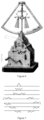
- Figure 6 illustrates a Villarceau governor made by Antoine Breguet in the 1870's and figure 7 illustrates the propagation of a singularity for a plucked string.
- This type of spring will be called a rotational isotropic oscillator and will be described in Section 4.1.
- the moment of inertia of the body affects the dynamics, as the body is rotating around itself.
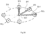
- FIG. 60 Translational orbit.
- Body 881 orbits around center 880, moving along orbit 883, but without rotating around its center of gravity. Its orientation remains unchanged, as seen by the constant direction of pointer 882 on the body.
- Planar isotropy may be realized in two ways.
- FIG. 16 A simple example is given in Figure 16 illustrating a simple planar isotropic spring with an orbiting mass 10, a y-coordinate spring 11, an x- coordinate spring 12, a y-spring fixation to ground 13, an x-spring fixation to ground 14, a horizontal ground 15, the y-axis being vertical so parallel to force of gravity.
- the two springs Sx 12 and Sy 11 of rigidity k are placed such that spring Sx 12 acts in the horizontal x -axis and spring Sy 11 acts in the vertical y-axis.
- the geometry is chosen such that at the point (0, 0) both springs are in their neutral positions.
- An embodiment illustrated in Figure 11 comprises two serial compliant four-bar 5 is also called parallel arms linkage, which allows, for small displacements, translations in the X and Y directions.
- Another embodiment, illustrated in figure 12 comprises four parallel arms 6 linked with eight spherical joints 7 and a central bellow 8 connecting the mobile platform 9 to the ground.
- the spring does not rotate around its own axis, minimizing spurious moments of inertia, and the central force is directly realized by the spring itself.
- isotropic springs because their restoring force is the same in all directions.
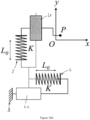
- FIG 18A A basic example of an embodiment of the oscillator made of planar isotropic springs is illustrated in figure 18A .
- Said figure illustrates a mechanical isotropic harmonic oscillator comprising at least a two degrees of freedom linkage L1/L2 made by appropriate guiding means (for example sliding means, or linkages, springs etc.), supporting an orbiting mass P with respect to a fixed base B with springs S having isotropic and linear restoring force K properties.
- appropriate guiding means for example sliding means, or linkages, springs etc.
- the first method to address the force of gravity is to make a planar isotropic spring which when in horizontal position with respect to gravity does not feel its effect.
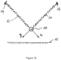
- Figure 19 illustrates an example of such a spring arrangement as a 2 degree of freedom planar isotropic spring construction.
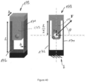
- gravity has negligible effect on the planar motion of the orbiting mass when the plane of mechanism is placed horizontally. This provides single direction minimization of gravitational effect. It comprises a fixed base 20, Intermediate block 21, a frame holding the orbiting mass 22, an orbiting mass 23, an y-axis parallel spring stage 24 and an x-axis parallel spring stage 25.
- figure 20 shows a gravity compensation in all directions for planar isotropic spring.
- Rigid frame 31 holds time base comprising two linked non-independent planar isotropic oscillators 32 (symbolically represented here).
- Lever 33 is attached to the frame 31 by a ball joint 34 (or XY universal joint).
- the two arms of the lever are telescopic thanks to two prismatic joints 35.
- the opposing ends of the lever 33 are attached to the orbiting masses 36 by ball joints.
- the mechanism is symmetric with respect to the point 0 at center of joint 34.
- Linear shocks are a form of linear acceleration, so include gravity as a special case.
- the mechanism of Figure 20 also compensates for linear shocks.
- Figure 21 illustrates gravity compensation in all directions for planar isotropic spring with added resistance to angular acceleration. This is achieved by minimizing the distance "I" between the center of gravity of the two orbiting masses.
- Rigid frame 41 holds a time base comprising of two linked non- independent planar isotropic oscillators 42 (symbolically represented here).
- Lever 43 is attached to the frame 41 by a ball joint 47 (or x-y universal joint).
- the two arms of the lever 43 are telescopic thanks to two prismatic joints 48.
- the opposing ends of the lever 43 are attached the orbiting masses 46 by ball joints 49.
- the mechanism is symmetric with respect to the point O at center of joint 47.
- Figure 22 illustrates another embodiment of a Realization of gravity compensation in all directions for a planar isotropic spring using flexures.
- a rigid frame 51 holds a time base comprising two linked non-independent planar isotropic oscillators 53 (symbolically represented here).
- Lever 54 is attached to a frame 52 by x-y a universal joint made of leaf spring 56 and flexible rod 57.
- the two arms of the lever 54 are telescopic thanks to two leaf springs 55.
- the opposing ends of the lever 54 are attached the orbiting masses 52 by the two leaf springs 55 which form two x-y universal joints.
- Figure 23 illustrates an alternate realization of gravity compensation in all directions for a planar isotropic spring using flexures.
- both ends of lever 64 are connected to the orbiting masse 62 connected to springs 63 in the oscillator by two perpendicular flexible rods 61.
- Figure 24 illustrates another realization of gravity compensation in all directions for an isotropic spring using flexures.
- fixed plate 71 holds time base comprising two linked symmetrically placed non-independent orbiting masses 72.
- Each orbiting mass 72 is attached to the fixed base by three parallel bars 73, these bars are either flexible rods or rigid bars with a ball joint 74 at each extremity.
- Lever 75 is attached to the fixed base by a membrane flexure joint (not numbered) and vertical flexible rod 78 thereby forming a universal joint.
- the extremities of the lever 75 are attached to the orbiting masses 72 via two flexible membranes 77.
- Part 79 is attached rigidly to part 71.
- Part 76 and 80 are attached rigidly to the lever 75.
- Oscillators lose energy due to friction, so there needs a method to maintain oscillator energy. There must also be a method for counting oscillations in order to display the time kept by the oscillator. In mechanical clocks and watches, this has been achieved by the escapement which is the interface between the oscillator and the rest of the timekeeper. The principle of an escapement is illustrated in figure 15 and such devices are well known in the watch industry.
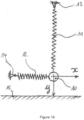
- a torque or a force are applied, see Figure 13 for the general principle of a torque T applied continuously to maintain the oscillator energy, and figure 14 illustrates another principle where a force F T is applied intermittently to maintain the oscillator energy.
- a mechanism is also required to transfer the suitable torque to the oscillator to maintain the energy, and in Figures 25 to 29 various crank embodiments according to the present invention for this purpose are illustrated.
- Figures 37 and 38 illustrate escapement systems for the same purpose.
- All these restoring energy mechanisms may be used in combination with the various embodiments of oscillators and oscillators systems (stages etc.) described herein, for example in figures 19 to 24 , 30 to 35 (as the mechanism 138 illustrated in figure 30 ), and 40 to 48 .
- the torque/force may by applied by the spring of the watch which is used in combination with an escapement as is known in the field of watches.
- the known escapement may therefore be replaced by the oscillator of the present invention.
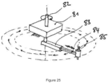
- FIG 25 illustrates the principle of a variable radius crank for maintaining oscillator energy.
- Crank 83 rotates about fixed frame 81 through pivot 82.
- Prismatic joint 84 allows crank extremity to rotate with variable radius.
- Orbiting mass of time base (not shown) is attached to the crank extremity 84 by pivot 85.
- the orientation of orbiting mass is left unchanged by crank mechanism and the oscillation energy is maintained by crank 83.
- Figure 26 illustrates a realization of variable radius crank for maintaining oscillator energy attached to the oscillator.
- a fixed frame 91 holds a crankshaft 92 on which maintaining torque M is applied.
- Crank 93 is attached to crankshaft 92 and equipped with a prismatic slot 93'.
- Rigid pin 94 is fixed to the orbiting mass 95 and engages in the slot 93'.
- the planar isotropic springs are represented by 96. Top view and perspective exploded views are shown in this figure 26 .
- Figure 27 illustrates a flexure based realization of a variable radius crank for maintaining oscillator energy.
- Crank 102 rotates about fixed frame (not shown) through shaft 105.
- Two parallel flexible rods 103 link crank 102 to crank extremity 101.
- Pivot 104 attaches the mechanism shown in figure 27 to an orbiting mass. The mechanism is shown in neutral singular position in this figure 27 .
- Figure 28 illustrates another embodiment of a flexure based realization of variable radius crank for maintaining oscillator energy.
- Crank 112 rotates about fixed frame (not shown) through shaft 115.
- Two parallel flexible rods 113 link crank 112 to crank extremity 111.
- Pivot 114 attaches mechanism shown to orbiting mass. Mechanism is shown in flexed position in this figure 28 .
- Figure 29 illustrates an alternate flexure based realization of variable radius crank for maintaining oscillator energy.
- Crank 122 rotates about fixed frame 121 through shaft.
- Two parallel flexible rods 123 link crank 122 to crank extremity 124.
- Pivot 126 attaches mechanism to orbiting mass 125. In this arrangement the flexible rods 123 are minimally flexed for average orbit radius.
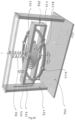
- Figure 30 illustrates an example of a completely assembled isotropic oscillator 131-137 and its energy maintaining mechanism according to the present invention. More specifically, a fixed frame 131 is attached to the ground or to a fixed reference (for example the object on or in which the oscillator is mounted) by three rigid feet 140 and top frame 140a. First compound parallel spring stage 131 holds second parallel spring stage 132 moving orthogonally to said spring stage 131. Compound parallel spring 132 is attached rigidly to stage 131. Fourth compound parallel spring stage 134 holds third parallel spring stage 133 moving orthogonally to spring stage 134. Outer frames of stages 131 and 134 are connected kinematically in the x and y directions by L-shaped brackets 135 and 136 as well as by notched leaf springs 137.
- stages 131 and 134 constitute the orbiting mass of the oscillator while stages 132-133 are attached together and fixed to feet 140 and the orbiting mass moves therefore relatively to stages 132-133.
- the moving mass may be formed by stages 132-133 and in that case the stages 131 and 134 are fixed to the feet 140.
- Bracket 139 mounted on the orbiting mass holds the rigid pin 138 (illustrated in figures 30 and 31 ) on which the maintaining force is applied for example a torque or a force, by means identical or equivalent to the ones described above with reference to figures 25-29 .
- Each stage 131-134 may be for example made as illustrated in figure 19 or in figures 42 to 46 discussed later herein in more details. Accordingly, the description of these figures applies to the stages 131-134 illustrated in these figures 30-35 .
- the stages 131 and 132 are identical but placed with a relative rotation (in particular of 90°) to form the XY planar isotropic springs discussed herein.
- Figure 31 shows the same embodiment of figure 30 , and shows the rigid pin 138 mounted rigidly on the orbiting masses (stages 134 and 131, for example as mentioned hereabove) and engages into slot 142 which acts as the driving crank and maintains the oscillation.
- the other parts are numbered as in figure 30 and the description of this figure applies correspondingly.
- the crank system used may be the one illustrated in figures 25-29 and described hereabove.
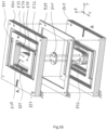
- Figure 32 illustrates the stages 131-134 of the embodiment of Figures 30 and 31 without crank system 142-143 and using the reference numbers of Figure 30 .
- Figure 33 illustrates the stages 131-133 of the embodiment of Figure 32 without stage 134 and using the reference numbers of Figure 30 .
- Figure 34 illustrates the stages 131-132 of the embodiment of Figure 33 without stage 3 using the reference numbers of Figure 30 .
- Figure 35 illustrates the stage 131 of Figure 34 without stage 132 using the reference numbers of Figure 30 .
- each stage 131-134 may be made in accordance with the embodiments described later in the present specification in reference to figures 41-46 .
- stage 131 of figure 35 comprises parallel springs 131a to 131d which hold a mass 131e and the springs and masses of said figures 41-48 may correspond to the ones of figures 30-35 .
- stages 131 and 132 are placed with a relative rotation of 90° between them, and their mass 131e-132e are attached together (see figure 34 ).
- This provides a construction equivalent to the one of figure 43 described later with two parallel springs in each direction XY.
- Stages 133 and 134 are attached as stages 131-132 and placed in a mirror configuration over stages 131-132, stage 133 comprising as stages 131 and 132 springs 133a-133d and a mass 133e.
- stage 133 rotated by 90° with respect to stage 132 as one can see in figure 33 .
- the frames of stages 132 and 133 are attached together such that they will not move relatively one to another.
- Stage 134 also comprise springs 134a-134d and mass 134e.
- Mass 134e is attached to mass 133e and the two stages 134 and 131 a linked together via brackets 135, 136 to form the orbiting mass while stages 132 and 133 which are attached together are fixed to the frame 140, 140a.
- the mechanism for applying a maintaining force or torque is placed on top of the stages 131-134 and comprises the pin 138 and the crank system 142, 143 which for example the system described in figure 26 , the pin 92 of figure 26 corresponding to pin 138 of figure 31 , the crank 93 corresponding to crank 142 and slot 93' to slot 143.
- stages 131-134 of figures 30-34 may be replaced by other equivalent stages having the XY planar isotropy in accordance with the principle of the invention, for example, one may use the configurations and exemplary embodiments of figures 40 to 46 to realize the oscillator of the present invention.
- the XY isotropic harmonic oscillators can be generalized by replacing X translation and Y translation by other motions, in particular, rotation.
- rotation When expressed as generalized coordinates in Lagrangian mechanics, the theory is identical and the mechanisms will have the same isotropic harmonic properties as the translational XY mechanisms.
- Figure 51 shows an example of an XY isotropic harmonic oscillator with generalized coordinates X a rotation and Y a rotation:
- two immobile beams 721 which support a rotating cage 722 via jewelled bearings at 721 and a spiral spring 724.
- a balance wheel allowed to rotate and attached via a balance staff (not shown) which rotates on jewelled bearings 723.
- a spiral spring 726 which provides a restoring force to the circular oscillation of the balance wheel around its axis.
- the spiral spring provides a restoring force to the rotation of the cage 722 around its neutral position where the balance wheel axis is perpendicular to the base 720.
- the moment of inertia of the balance wheel assembly including the cage is such that the natural frequencies of the balance wheel and spring 725 is the same as that of the cage and balance wheel and spring 724.
- the oscillations of the balance wheel model the isotropic harmonic oscillator and for small amplitudes of oscillations the mass 727 on the balance wheel moves in a unidirectional orbit approximating an ellipse as shown in Figure 52 .
- This mechanism has the advantage of being insensitive to linear acceleration and gravity, as opposed to the standard translational XY isotropic oscillator. Its properties are Isotropic k Radial k Zero J Isotropic m Radial m Gravity Linear shock Angular shock Yes Yes Yes Yes Yes Yes Yes No
- Figure 52 shows that a pin placed on the balance wheel in Figure 51 has a roughly elliptical orbit on a sphere, allowing this mechanism to be maintained by a rotating crank as with the XY translational isotropic harmonic oscillators.
- the figure describes the motion of the mass 727 of Figure 51 as the balance and cage oscillate.
- the sphere 734 represents the space of all possible positions of the mass 727 for arbitrarily large oscillations of the balance wheel and cage. Shown in the figure is the situation for a small oscillation in which the mass 732 moves along a periodic orbit 733 around its neutral point 731. The angular motion of the mass 732 is always in the same angular direction and does not stop.
- Figure 53 shows that if the X and Y angles are graphed on a plane, then the same elliptical orbit is recovered as in the X and Y translational case.
- the figure describes the angular parameters of the mechanism of Figure 51 .
- the mass 741 represents the mass 727 of Figure 51 .
- the angle theta represents the angle of rotation of the balance wheel of Figure 53 around its axis, with respect to its neutral position and the angle phi represents the angle of rotation of the cage 722 of Figure 53 around its axis, with respect to its neutral position.
- the mass 741 moves in the periodic orbit 742 around its neutral point 740.
- the orbit 742 is a perfect ellipse and following Newton's result, all such orbits will have the same period.
- Figure 54 shows an example of an XY isotropic harmonic oscillator with X a translation and Y a rotation. It can be seen that a pin on the balance wheel has a roughly elliptical orbit, so this mechanism can be maintained by a rotating crank as with the XY translational isotropic harmonic oscillators.
- To the fixed base 750 are attached two vertical immobile beams 751. At the top of the two beams 751 is a horizontal beam (transparent here), to which is attached a collet holding a cylindrical spring 756. The bottom of the cylindrical spring 756 is attached via a collet to the cage 753, allowing the cage to translate vertically via two grooves 754 on each of the vertical posts 751, the grooves hold the cage axes 755.
- the cylindrical spring 756 provides a linear restoring force to produce translational oscillation of the cage.
- the cage 754 contains a spiral spring 757 attached to a balance wheel 758.
- the spiral spring provides a restoring torque to the balance wheel which causes it to have a isotropic oscillation.
- the frequency of the translational oscillation of the cage 753 is designed to equal the frequency of the angular oscillation of the balance wheel 758, for small amplitudes the balance weights 759 move in a unidirectional rotation approximating an ellipse.
- the advantage of using an escapement is that the oscillator will not be continuously in contact with the energy source (via the gear train) which can be a source of chronometric error.
- the escapements will therefore be free escapements in which the oscillator is left to vibrate without disturbance from the escapement for a significant portion of its oscillation.
- the escapements are simplified compared to balance wheel escapements since the oscillator is turning in a single direction. Since a balance wheel has a back and forth motion, watch escapements generally require a lever in order to impulse in one of the two directions.
- the first watch escapement which directly applies to our oscillator is the chronometer or detent escapement [6, 224-233].
- This escapement can be applied in either spring detent or pivoted detent form without any modification other than eliminating passing spring whose function occurs during the opposite rotation of the ordinary watch balance wheel, see [6, Figure 471c].
- Figure 4 illustrating the classical detent escapement the entire mechanism is retained except for Gold Spring i whose function is no longer required.
- Embodiments of possible detent escapements for the isotropic harmonic oscillator are shown in Figures 36 to 38 .
- Figure 36 illustrates a simplified classical detent watch escapement for an isotropic harmonic oscillator.
- the usual horn detent for reverse motion has been suppressed due to the unidirectional rotation of the oscillator.
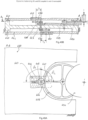
- Figure 37 illustrates an embodiment of a detent escapement for translational orbiting mass.
- Two parallel catches 151 and 152 are fixed to the orbiting mass (not shown but illustrated schematically by the arrows forming a circle, reference 156) so have trajectories that are synchronous translations of each other Catch 152 displaces detent 154 pivoted at spring 155 which releases escape wheel 153. Escape wheel impulses on catch 151, restoring lost energy to the oscillator
- Figure 38 illustrates an embodiment of a new detent escapement for translational orbiting mass.
- Two parallel catches 161 and 162 are fixed to the orbiting mass (not shown) so have trajectories that are synchronous translations of each other Catch 162 displaces detent 164 pivoted at spring 165 which releases escape wheel 163. Escape wheel impulses on catch 161, restoring lost energy to the oscillator Mechanism allows for variation of orbit radius. Side and top views shown in this figure 38 .
- Figure 39 illustrates examples of compliant XY-stages of the prior art.
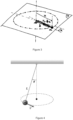
- the conical pendulum is a pendulum rotating around a vertical axis, that is, perpendicular to the force of gravity, see Figure 4
- the theory of the conical pendulum was first described by Christiaan Huygens see references [16] and [7] who showed that, as with the ordinary pendulum, the conical pendulum is not isochronous but that, in theory, by using a flexible string and paraboloid structure, can be made isochronous.
- Huygens' modification is based on a flexible pendulum and in practice does not improve timekeeping.
- the conical pendulum has never been used as a timebase for a precision clock.
- the conical pendulum has been consistently described as a method for obtaining uniform motion in order to measure small time intervals accurately, for example, by Defossez in his description of the conical pendulum see reference [8, p. 534].
- the conical pendulum has been used in precision clocks, but never as a time base.
- William Bond constructed a precision clock having a conical pendulum, but this was part of the escapement, the timebase being a circular pendulum see references [10] and [25, p. 139-143].
- our invention is therefore a superior to the conical pendulum as choice of time base because our oscillator has inherent isochronism. Moreover, our invention can be used in a watch or other portable timekeeper, as it is based on a spring, whereas this is impossible for the conical pendulum which depends on the timekeeper having constant orientation with respect to gravity
- governors are mechanisms which maintain a constant speed, the simplest example being the Watt governor for the steam engine.
- these governors were used in applications where smooth operation, that is, without the stop and go intermittent motion of a clock mechanism based on an oscillator with escapement, was more important than high precision.
- such mechanisms were required for telescopes in order to follow the motion of the celestial sphere and track the motion of stars over relatively short intervals of time. High chronometric precision was not required in these cases due to the short time interval of use.
- Our invention uses a mechanical oscillator as time base and does not require electricity or electronics in order to operate correctly.
- the continuous motion of the movement is regulated by the isotropic oscillator itself and not by an integrated circuit.
- the present invention was conceived as a realization of the isotropic harmonic oscillator for use as a time base. Indeed, in order to realize the isotropic harmonic oscillator as a time base, there requires a physical construction of the central restoring force.
- the theory of a mass moving with respect to a central restoring force is such that the resulting motion lies in a plane. It follows that for practical reasons, that the physical construction should realize planar isotropy. Therefore, the constructions described here will mostly be of planar isotropy, but not limited to this, and there will also be an example of 3-dimensional isotropy. Planar isotropy can be realized in two ways: isotropic isotropic springs and translational isotropic springs.
- Isotropic isotropic springs have one degree of freedom and rotate with the support holding both the spring and the mass. This architecture leads naturally to isotropy. While the mass follows the orbit, it rotates about itself at the same angular velocity as the support. This leads to a spurious moment of inertia so that the mass no longer acts as a point mass and the departure from the ideal model described in Section 1.1 and therefore to a theoretical isochronism defect.
- Translational isotropic springs have two translational degrees of freedom in which the mass does not rotate but translates along an elliptical orbit around the neutral point. This does away with spurious moment of inertia and removes the theoretical obstacle to isochronism.
- a rotating cantilever spring 3 supported in a cage 4 turning axially is illustrated in Figure 9 , discussed above. This again realizes the central linear restoring force but reduces spurious moment of inertia by having a cylindrical mass and an axial spring. Numerical simulation shows that divergence from isochronism is still significant.
- a physical model has been constructed, see Figure 10 , where vertical motion of the mass has been minimized by attaching the mass to a double leaf spring producing approximately linear displacement instead of the approximately circular displacement of the single spring of Figure 9 . The data from this physical model is consistent with the analytic model.
- Compliant XY-stages are mechanism with two degrees of freedom both of which are translations. As these mechanisms comprise compliant joints, see reference [28], they exhibit planar restoring forces so can be considered as planar springs.
- the first one, illustrated in Figure 11 comprises two serial compliant four-bar 5 mechanisms, also called parallel arms linkage, which allows, for small displacements translations in the X and Y directions
- the second one, illustrated in Figure 12 comprises four parallel arms 6 linked with eight spherical joints 7 and a bellow 8 connecting the mobile platform 9 to the ground
- the same result can be obtained with three parallel arms linked and with eight spherical joints and a bellow connecting the mobile platform to the ground.
- Isotropic springs are one object of the present invention and they appear most suitable to preserve the theoretical characteristics of the harmonic oscillator are the ones in which the central force is realized by an isotropic spring, where the term isotropic is again used to mean "same in all directions.”
- FIG. 18A is basic illustration of the principle of the present invention (see above for its detailed description).
- This model has two degrees of freedom as opposed to the model of Section 11.2 which has six degrees of freedom. Therefore, this model is truly planar, as is required for the theoretical model of Section 2. Finally, this model is insensitive to gravity when its plane is orthogonal to gravity.
- a first plate 181 is mounted on top of a second plate 182.
- Blocks 183 and 184 of first plate 181 are fixed onto blocks 185 and 186 respectively of second plate 182.
- the grey shaded blocks 184, 187 of first plate and 186 of second plate 182 have a y-displacement corresponding to the y-component displacement of the orbiting mass 189, while the black shaded blocks 183 of the first plate 181 and 185, 188 of the second plate 182 remain immobile.
- the grey shaded blocks 184, 187 of first 181 and 186 of second plate 182 have an x-displacement corresponding to the x-component displacement of the orbiting mass 189 while the black shaded blocks 183, 185, 188 of the first 181 and second 182 plates remain immobile. Since the first and second plates 181, 182 are identical, the sum of the masses of 184, 187 and 186 is equal to the sum of the masses of 184, 188 and 186. Therefore, the total mobile mass (grey blocks 184, 186, 187) is the same for displacements in x and in y directions, as well as in any direction of the plane.
- the reduced mass in the x and y directions are identical and therefore the same in every planar direction, thus in theory minimizing reduced mass isotropy defect.
- the goal of this mechanism is to provide an isotropic spring stiffness.
- Isotropy defect that is, the variation from perfect spring stiffness isotropy, will be the factor minimized in our invention.
- Our inventions will be presented in order of increasing complexity corresponding to compensation of factors leading to isotropy defects.
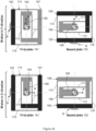
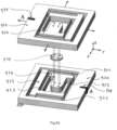
- FIGS 43 and 44 illustrate an embodiment of an in plane orthogonal compensated parallel spring stages according to the invention.
- Fixed base 191 holds first pair of parallel leaf springs 192 connected to intermediate block 193.
- Second pair of leaf springs 194 (parallel to 192) connect to second intermediate block 195.
- Intermediate block 195 holds third pair of parallel leaf springs 196 (orthogonal to springs 192 and 194) connected to third intermediate block 197.
- Intermediate block 197 holds parallel leaf springs 198 (parallel to springs 196) which are connected to orbiting mass 199 or alternatively to a frame holding the orbiting mass 199.
- the in-plane orthogonal non-compensated parallel spring stages mechanism has a worst case isotropy defect of 6.301%.
- worst case isotropy is 0.027%. The compensated mechanism therefore reduces the worst case isotropy stiffness defect by a factor of 200.
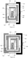
- figure 46 discloses an embodiment minimizing the reduced mass isotropy defect.
- a first plate 201 is mounted on top of a second plate 202 and the numbering has the same significance as in Figure 43 .
- Blocks 191 and 199 of first plate 201 are fixed onto blocks 191 and 199 respectively of second plate 202.
- the grey shaded blocks 197, 199 of first plate 201 and 193, 195, 197, 199 of second plate 202 have an x-displacement corresponding to the x-component displacement of the orbiting mass while the black shaded blocks 191, 193, 195 of the first plate 201 and 191 of the second plate 202 remain immobile.
- the grey shaded blocks 193, 195, 197, 199 of first plate 201 and 199 of second plate 202 have a y-displacement corresponding to the y-component displacement of the orbiting mass while the black shaded block 191 of the first plate 201 and 191, 193, 195 of the second plate 202 remain immobile.
- the reduced mass in the x and y directions are identical and therefore identical in every direction, thus in theory minimizing reduced mass isotropy defect.
- a fixed base 301 holds first pair of parallel leaf springs 302 connected to intermediate block 303.
- Second pair of leaf springs 304 (parallel to 302) connect to second intermediate block 305.
- Intermediate block 305 holds third pair of parallel leaf springs 306 (orthogonal to springs 302 and 304) connected to third intermediate block 307.
- Intermediate block 307 holds parallel leaf springs 308 (parallel to 306) which are connected to orbiting mass 309 (or alternatively frame holding the orbiting mass 309).
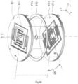
- Figure 55 illustrates a parallel assembly of two identical XY parallel spring oscillators for amelioration of the stiffness isotropy.
- the first XY parallel spring stage oscillator (upper stage on figure 55 ) comprises a fixed outer frame 830, a first pair of parallel leaf springs 831 and 832, an intermediate block 833, a second pair of parallel leaf springs 834 and 835, and a mobile block 838 on which the orbiting mass (not shown on the figure) is to be rigidly mounted.
- the second XY parallel spring stage (lower stage on figure 55 ) is identical to the first. Both stages are mounted together by rigidly attaching 830 to 841 and 836 to 842.
- the second XY parallel spring stage is rotated 180 degrees around the Z axis with respect to the first one (the figure shows that indexing-notch A on 830 is opposite to indexing-notch A in 841). Since the isotropy defect of a single stage is periodic, stacking two stages in parallel with the correct angular offset (in this case 180 degrees) leads to anti-phase cancellation of the defect. Shims 840 and 839 are used to separate slightly the two stages and avoid any friction between their mobile parts.
- the stiffness isotropy defect of the complete assembly is significantly smaller (typically a factor 2 to 20) than that of a single XY parallel spring stage.
- the stiffness isotropy can be further improved by stacking more than two stages rotated by angles smaller than 180 degrees.
- Figure 56 illustrates a parallel assembly of two identical XY compound parallel spring oscillators for amelioration of the stiffness isotropy.
- the first XY compound parallel spring stage (upper part on figure 84) comprises a fixed outer frame 850 connected to a mobile block 851 via two perpendicular compound parallel spring stages mounted in series. The orbiting mass (not shown on the figure) is to be rigidly mounted onto the mobile block 851.
- the second XY compound parallel spring stage (lower part on figure 84) is identical to the first. It comprises a fixed outer frame 852 connected to a mobile rigid block 853 via two perpendicular compound parallel spring stages mounted in series. Both stages are mounted together by rigidly attaching 850 onto 852 and 851 onto 853.
- the second XY parallel spring stage is rotated 45 degrees around Z with respect to the first one (the figure shows that the indexing-notch A on 852 is rotated 45 degrees with respect to indexing-notch A in 850). Since the isotropy defect of a single stage is periodic, stacking two stages in parallel with the correct angular offset (in this case 45 degrees) leads to anti-phase cancellation of the defect. Shims 854 and 855 are used to separate slightly the two stages and avoid any friction between the mobile parts.
- the stiffness isotropy defect of the complete assembly is significantly smaller (typically a factor 100 to 500) than that of a single XY compound parallel spring stage. Note 1: The stiffness isotropy can be further improved by stacking more than two stages rotated by angles smaller than 45 degrees.
- the embodiments illustrated in figures 55 and 56 are applicable to the constructions and embodiments described hereinabove and illustrated in figures 30 to 35 and 40 to 46 which comprise similar stages.
- stacks comprising several stages (two or more) may be formed by stacking them on top of each other, each stage having an angular offset for example 45°, 90°, 180° or other values or even a combination thereof with respect to its neighboring stage, according to the principle described hereabove.
- Such combination of stages oriented with different angles allow reduction or even cancellation of the isotropy defect of the oscillator.
- Figure 62 illustrates a serial assembly of two identical XY parallel spring oscillators for amelioration of the stiffness isotropy.
- the first XY parallel spring stage oscillator (lower stage on figure 62 ) comprises a fixed outer frame 970, a first pair of parallel leaf springs 971, an intermediate block 972, a second pair of parallel leaf springs 973, and a mobile block 974 on which the second XY parallel spring stage (upper stage on figure 62 ) is rigidly mounted.
- This second stage is identical to the first one. Both stages are mounted together by rigidly attaching 976 to 974 via a shim 975 creating a gap between the two stages.
- the second stage is rotated 180 degrees around the Z axis with respect to the first one (the figure shows that indexing-notch A on 970 is opposite to indexing-notch A in 979).
- the mobile mass of the oscillator is the block 977 (this block is made out of dense material whereas all the other mobiles blocks are made of low density material). Since the isotropy defect of a single stage is periodic, stacking two stages serially with the correct angular offset (in this case 180 degrees) leads to anti-phase cancellation of the defect.
- the stiffness isotropy defect of the complete assembly is significantly smaller (typically a factor 2 to 20) than that of a single XY parallel spring stage.
- the stiffness isotropy can be further improved by stacking more than two stages rotated by angles smaller than 180 degrees. Its properties are Isotropic k Radial k Zero J Isotropic m Radial m Gravity Linear shock Angular shock Yes Yes Yes Yes no No No No
- Figure 63 illustrates a serial assembly of two identical XY compound parallel spring oscillators for amelioration of the stiffness isotropy.
- the first XY parallel spring stage oscillator (lower stage on figure 63 ) comprises a fixed outer frame 980, and a mobile block 981 on which the second XY compound parallel spring stage (upper stage on figure 63 ) is rigidly mounted.
- This second stage is identical to the first one. Both stages are mounted together by rigidly attaching 981 to 983 via a shim 982 creating a gap between the two stages.
- the second stage is rotated 45 degrees around the Z axis with respect to the first one (the figure shows that indexing-notch A on 984 is shifted with respect to indexing-notch A in 980).
- the mobile mass of the oscillator is the block 984 (this block is made out of dense material whereas all the other mobiles blocks are made of low density material). Since the isotropy defect of a single stage is periodic, stacking two stages serially with the correct angular offset (in this case 45 degrees) leads to anti-phase cancellation of the defect.
- the stiffness isotropy defect of the complete assembly is significantly smaller (typically a factor 100 to 500) than that of a single XY parallel spring stage.
- the stiffness isotropy can be further improved by stacking more than two stages rotated by angles smaller than 45 degrees. Its properties are Isotropic k Radial k Zero J Isotropic m Radial m Gravity Linear shock Angular shock Yes Yes Yes Yes no No No No
- the first method to address the force of gravity is to make a planar isotropic spring which when in horizontal position with respect to gravity does not feel its effect as described above.
- Linear shocks are a form of linear acceleration, so include gravity as a special case.
- the mechanism of Figure 20 also compensates for linear shocks, see description above.
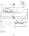
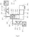
- the orbiting masses 643 and 644 of two planar oscillators are coupled by a double crank (similar to a bicycle crankset) comprising an upper crank 646, a lower crank 645 and their shaft 647 (similar to a bicycle bottom bracket).
- Crank arm 646 contains a slot allowing a pin rigidly connected to mass 643 to slide in this slot.
- mass 644 is rigidly connected to a pin sliding in a slot on crank 645.
- Shaft 647 is driven by a gear 648 which is itself driven by a gear 649, which in turn is driven by a gear 650. This arrangement forces both masse 643 and 644 to orbit at 180 degrees from each other (angular coupling).
- the radial positions of the two masses are independent (no radial coupling).
- the full system thus behaves as a three degrees of freedom oscillator.
- the fixed frame 641 and 642 of the upper and lower oscillators are attached to a common fixed frame 640. Its properties are Isotropic k Radial k Zero J Isotropic m Radial m Gravity Linear shock Angular shock Yes Yes Yes Yes Yes Yes Yes Partially Partially No
- Figures 50A and 50B illustrate a dynamically balanced angularly and radially coupled double oscillator based on two planar oscillators.
- Orbiting masses 653 and 655 of two planar oscillators 654 and 652 are coupled by a coupling bar 656 connected to the fixed frame 651 by a ball joint 657.
- the two extremities of 656 slide axially into two spheres 658 and 659 forming ball joint articulations with respect to 655 and 653 respectively.
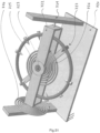
- Figure 57 illustrates a dynamically balanced isotropic harmonic oscillator:
- the orbiting mass 867 (M) in mounted onto a frame 866.
- the frame 866 is attached to the fixed base 860 via two parallel spring stages mounted in series at 90 degrees: 861 and 862 provide a degree-of-freedom in the Y direction, and 864 and 865 provide a degree-of-freedom in the X direction.
- 863 is an intermediate mobile block.
- 866 is connected to an X compensating mass 871 (m) moving in opposite direction for all movements in the X direction of 867, and to a Y direction compensating mass 876 moving in opposite direction for all movements in the Y direction.
- the inversion mechanism is based on a leaf spring 869 connecting the main mass 867 to a rigid lever 870.
- the lever pivots with respect to the fixed base thanks to a flexure-pivot comprising two leaf springs 872 and 873.
- the X direction compensating mass 871 is mounted onto the opposite end of the lever.
- An identical mechanism 874 to 878 is used to balance the main mass 867 dynamically for acceleration in the Y direction.
- the overall mechanism is thus highly insensitive to linear accelerations in the range of small deformations.
- a rigid pin 868 is attached to 867 and engages into the driving crank (not shown in the figure) maintaining the orbiting motion. Note: all parts except the masses 867, 871 and 876 are made out of a low-density material, for example aluminum alloy or silicon.
- FIG. 48 A three dimensional translational isotropic spring is illustrated in Figure 48 .
- Three perpendicular bellows 403 connect to translational orbiting mass 402 to fixed base 401.
- this mechanism exhibits three dimensional isotropy up to first order.
- the bellows 403 provide a 3 degree-of-freedom translational suspension making this a realistic working mechanism insensitive to external torque. Its properties are Isotropic k Radial k Zero J Isotropic m Radial m Gravity Linear shock Angular shock Yes Yes Yes Yes No No No No No No
- the oscillators and systems described in the present application may be used as a time base for a chronograph measuring fractions of seconds requiring only an extended speed multiplicative gear train, for example to obtain 100Hz frequency so as to measure 1/100 th of a second.
- a chronograph measuring fractions of seconds requiring only an extended speed multiplicative gear train, for example to obtain 100Hz frequency so as to measure 1/100 th of a second.
- the gear train final ratio may be adapted in consequence.
- the oscillator described herein may be used as a speed governor where only constant average speed over small intervals is required, for example, to regulate striking or musical clocks and watches, as well as music boxes.
- the use of a harmonic oscillator, as opposed to a frictional governor, means that friction is minimized and quality factor optimized thus minimizing unwanted noise, decreasing energy consumption and therefore energy storage, and in a striking or musical watch application, thereby improving musical or striking rhythm stability.
Landscapes
- Physics & Mathematics (AREA)
- General Physics & Mathematics (AREA)
- Engineering & Computer Science (AREA)
- Acoustics & Sound (AREA)
- Multimedia (AREA)
- Apparatuses For Generation Of Mechanical Vibrations (AREA)
- Micromachines (AREA)
- Springs (AREA)
- Electric Clocks (AREA)
- Measurement Of Unknown Time Intervals (AREA)
Priority Applications (1)
| Application Number | Priority Date | Filing Date | Title |
|---|---|---|---|
| EP15706927.9A EP3095010B1 (en) | 2014-01-13 | 2015-01-13 | Isotropic harmonic oscillator and associated time base without escapement or with simplified escapement |
Applications Claiming Priority (7)
| Application Number | Priority Date | Filing Date | Title |
|---|---|---|---|
| EP14150939 | 2014-01-13 | ||
| EP14173947.4A EP2894521A1 (en) | 2014-01-13 | 2014-06-25 | Isotropic harmonic oscillator and associated time base without escapement or simplified escapement |
| EP14183385 | 2014-09-03 | ||
| EP14183624 | 2014-09-04 | ||
| EP14195719 | 2014-12-01 | ||
| PCT/IB2015/050242 WO2015104692A2 (en) | 2014-01-13 | 2015-01-13 | Xy isotropic harmonic oscillator and associated time base without escapement or with simplified escapement |
| EP15706927.9A EP3095010B1 (en) | 2014-01-13 | 2015-01-13 | Isotropic harmonic oscillator and associated time base without escapement or with simplified escapement |
Publications (2)
| Publication Number | Publication Date |
|---|---|
| EP3095010A2 EP3095010A2 (en) | 2016-11-23 |
| EP3095010B1 true EP3095010B1 (en) | 2024-09-25 |
Family
ID=66646802
Family Applications (1)
| Application Number | Title | Priority Date | Filing Date |
|---|---|---|---|
| EP15706927.9A Active EP3095010B1 (en) | 2014-01-13 | 2015-01-13 | Isotropic harmonic oscillator and associated time base without escapement or with simplified escapement |
Country Status (7)
| Country | Link |
|---|---|
| US (1) | US10365609B2 (enExample) |
| EP (1) | EP3095010B1 (enExample) |
| JP (1) | JP6559703B2 (enExample) |
| CN (1) | CN107250925B (enExample) |
| HK (2) | HK1231572A1 (enExample) |
| RU (2) | RU2686869C2 (enExample) |
| WO (1) | WO2015104692A2 (enExample) |
Families Citing this family (16)
| Publication number | Priority date | Publication date | Assignee | Title |
|---|---|---|---|---|
| RU2686869C2 (ru) | 2014-01-13 | 2019-05-06 | Эколь Политекник Федераль Де Лозанн (Епфл) | Изотропный гармонический осциллятор и соответствующий регулятор с отсутствующим спусковым механизмом или с упрощенным спусковым механизмом |
| EP3095011B1 (en) * | 2014-01-13 | 2022-11-30 | Ecole Polytechnique Fédérale de Lausanne (EPFL) | Orbiting masses system |
| EP3054357A1 (fr) * | 2015-02-03 | 2016-08-10 | ETA SA Manufacture Horlogère Suisse | Mécanisme oscillateur d'horlogerie |
| US12265359B2 (en) | 2016-07-06 | 2025-04-01 | Ecole Polytechnique Federale De Lausanne (Epfl) | General 2 degree of freedom isotropic harmonic oscillator and associated time base without escapement or with simplified escapement |
| CH712726A2 (fr) * | 2016-07-21 | 2018-01-31 | Montres Breguet Sa | Oscillateur balancier-spiral d'horlogerie à pivot magnétique. |
| CH713069A2 (fr) * | 2016-10-25 | 2018-04-30 | Eta Sa Mft Horlogere Suisse | Montre mécanique avec résonateur rotatif isochrone, insensible aux positions. |
| CH713288A1 (fr) | 2016-12-23 | 2018-06-29 | Sa De La Manufacture Dhorlogerie Audemars Piguet & Cie | Composant monolithique flexible pour pièce d'horlogerie. |
| CH713829B1 (fr) * | 2017-05-24 | 2022-01-14 | Mft Dhorlogerie Audemars Piguet Sa | Dispositif de régulation pour pièce d'horlogerie avec oscillateur harmonique isotrope ayant des masses rotatives et une force de rappel commune. |
| WO2018215284A1 (fr) | 2017-05-24 | 2018-11-29 | Sa De La Manufacture D'horlogerie Audemars Piguet & Cie | Dispositif de régulation pour pièce d'horlogerie avec oscillateur harmonique isotrope ayant des masses rotatives et une force de rappel commune |
| CH713822A2 (fr) * | 2017-05-29 | 2018-11-30 | Swatch Group Res & Dev Ltd | Dispositif et procédé d'ajustement de marche et correction d'état d'une montre. |
| US20210208537A1 (en) * | 2017-10-02 | 2021-07-08 | Manufacture D'horlogerie Audemars Piguet Sa | Timepiece setting device with harmonic oscillator having rotating weights and a common recoil strength |
| EP3740820B1 (en) * | 2018-01-18 | 2021-12-22 | Ecole Polytechnique Fédérale de Lausanne (EPFL) | Horological oscillator |
| EP3719584A1 (en) | 2019-04-02 | 2020-10-07 | Ecole Polytechnique Fédérale de Lausanne (EPFL) | Two degree of freedom oscillator system |
| EP3739394A1 (en) | 2019-05-16 | 2020-11-18 | Ecole Polytechnique Fédérale de Lausanne (EPFL) | Crank arrangement for driving a mechanical oscillator |
| EP3757684B1 (fr) * | 2019-06-26 | 2024-10-16 | The Swatch Group Research and Development Ltd | Mobile inertiel pour resonateur d'horlogerie avec dispositif d'interaction magnetique insensible au champ magnetique externe |
| EP3926412A1 (fr) * | 2020-06-16 | 2021-12-22 | Montres Breguet S.A. | Mécanisme régulateur d'horlogerie |
Family Cites Families (25)
| Publication number | Priority date | Publication date | Assignee | Title |
|---|---|---|---|---|
| FR73414A (fr) | 1866-10-26 | 1866-12-18 | Des procédés applicables à l'horlogerie et au réglage de la vitesse des machines | |
| CH113025A (de) * | 1924-04-28 | 1925-12-16 | Heinrich Schieferstein Georg | Verfahren zur Steuerung eines Drehbewegungen ausführenden Mechanismus. |
| CH406984A (de) * | 1964-01-20 | 1965-09-15 | Centre Electron Horloger | Mechanischer Resonator für Normalfrequenzoszillatoren in Zeitmessgeräten |
| CH452443A (fr) * | 1964-07-10 | 1968-05-31 | Movado Montres | Oscillateur pour pièces d'horlogerie |
| FR1457957A (fr) | 1965-12-10 | 1966-11-04 | Boddaert A | Perfectionnements aux balanciers de mouvements d'horlogerie |
| CH482232A (de) | 1966-10-17 | 1970-01-15 | Straumann Inst Ag | Einrichtung mit einem Klinkenrad und mindestens einem zu seinem Antrieb dienenden tonfrequenten Schwingorgan in einem Zeitmessgerät |
| CH510902A (fr) * | 1967-06-27 | 1971-01-29 | Movado Montres | Résonateur de rotation mécanique pour appareil de mesure du temps |
| CH481411A (fr) | 1967-06-27 | 1969-12-31 | Movado Montres | Résonateur de rotation mécanique pour appareil de mesure du temps |
| CH512757A (fr) | 1967-06-27 | 1971-05-14 | Movado Montres | Résonateur de rotation mécanique pour appareil de mesure du temps |
| US3540208A (en) | 1968-05-22 | 1970-11-17 | Bruce A Kock | Hydraulic watch |
| DE1815099A1 (de) * | 1968-12-17 | 1970-09-24 | Mauthe Gmbh Friedr | Oszillator als Gangordner von insbesondere elektrischen Uhren |
| DE2354226A1 (de) | 1973-10-30 | 1975-05-07 | Kieninger & Obergfell | Drehpendel, vorzugsweise torsionspendel |
| JPS52133255A (en) | 1976-05-01 | 1977-11-08 | Rhythm Watch Co | Pendulum device for clock |
| JPS6223211A (ja) * | 1985-07-23 | 1987-01-31 | Nec Corp | 誘電体共振器制御発振逓倍器 |
| CN1418295A (zh) | 2000-07-11 | 2003-05-14 | 精工爱普生株式会社 | 弹簧、驱动机构以及应用这种弹簧的装置和时计 |
| ATE390654T1 (de) * | 2002-02-01 | 2008-04-15 | Tag Heuer Sa | Vorrichtung mit uhrwerk und chronographenmodul |
| ATE459026T1 (de) * | 2003-12-16 | 2010-03-15 | Montres Breguet Sa | Chronometerhemmung für uhren |
| EP1645918A1 (fr) * | 2004-10-05 | 2006-04-12 | Montres Breguet S.A. | Dispositif anti-galop pour échappement d'horlogerie |
| JP4992319B2 (ja) * | 2006-07-10 | 2012-08-08 | セイコーエプソン株式会社 | 時計 |
| US7449859B2 (en) * | 2007-02-20 | 2008-11-11 | Gm Global Technology Operations, Inc. | Reduction of subharmonic oscillation at high frequency operation of a power inverter |
| EP2090941B1 (fr) * | 2008-02-18 | 2011-10-19 | CSEM Centre Suisse d'Electronique et de Microtechnique SA - Recherche et Développement | Oscillateur mecanique |
| JP4977220B2 (ja) * | 2010-02-23 | 2012-07-18 | 日本電波工業株式会社 | 基本波/オーバートーン水晶発振器 |
| EP2466401B1 (fr) | 2010-12-15 | 2013-08-14 | Asgalium Unitec SA | Résonateur magnétique pour pièce d'horlogerie mécanique |
| RU2686869C2 (ru) | 2014-01-13 | 2019-05-06 | Эколь Политекник Федераль Де Лозанн (Епфл) | Изотропный гармонический осциллятор и соответствующий регулятор с отсутствующим спусковым механизмом или с упрощенным спусковым механизмом |
| EP3054357A1 (fr) | 2015-02-03 | 2016-08-10 | ETA SA Manufacture Horlogère Suisse | Mécanisme oscillateur d'horlogerie |
-
2015
- 2015-01-13 RU RU2016130167A patent/RU2686869C2/ru not_active IP Right Cessation
- 2015-01-13 US US15/109,821 patent/US10365609B2/en active Active
- 2015-01-13 JP JP2016563279A patent/JP6559703B2/ja not_active Expired - Fee Related
- 2015-01-13 CN CN201580013815.6A patent/CN107250925B/zh not_active Expired - Fee Related
- 2015-01-13 EP EP15706927.9A patent/EP3095010B1/en active Active
- 2015-01-13 HK HK17105186.4A patent/HK1231572A1/zh unknown
- 2015-01-13 HK HK17105184.6A patent/HK1231571A1/zh unknown
- 2015-01-13 WO PCT/IB2015/050242 patent/WO2015104692A2/en not_active Ceased
- 2015-01-13 RU RU2016130168A patent/RU2686446C2/ru not_active IP Right Cessation
Non-Patent Citations (2)
| Title |
|---|
| AWTAR SHORYA: "Synthesis and Analysis of Parallel Kinematic XY Flexure Mechanisms", 19 December 2003 (2003-12-19), pages 1 - 198, XP093102008, Retrieved from the Internet <URL:https://psdl.engin.umich.edu/pdf/T2.pdf> [retrieved on 20231115] * |
| AWTAR, S.: "Synthesis and analysis of parallel kinematic XY flexure mechanisms", PH.D. THESIS, 2006 * |
Also Published As
| Publication number | Publication date |
|---|---|
| RU2686446C2 (ru) | 2019-04-25 |
| RU2686869C2 (ru) | 2019-05-06 |
| US20160327910A1 (en) | 2016-11-10 |
| EP3095010A2 (en) | 2016-11-23 |
| JP2017502317A (ja) | 2017-01-19 |
| HK1231571A1 (zh) | 2017-12-22 |
| CN107250925A (zh) | 2017-10-13 |
| RU2016130167A (ru) | 2018-02-20 |
| RU2016130168A3 (enExample) | 2018-06-25 |
| JP6559703B2 (ja) | 2019-08-14 |
| WO2015104692A2 (en) | 2015-07-16 |
| WO2015104692A3 (en) | 2016-01-21 |
| HK1231572A1 (zh) | 2017-12-22 |
| RU2016130168A (ru) | 2018-02-20 |
| US10365609B2 (en) | 2019-07-30 |
| RU2016130167A3 (enExample) | 2018-06-28 |
| CN107250925B (zh) | 2020-06-23 |
Similar Documents
| Publication | Publication Date | Title |
|---|---|---|
| EP3095010B1 (en) | Isotropic harmonic oscillator and associated time base without escapement or with simplified escapement | |
| US10585398B2 (en) | General two degree of freedom isotropic harmonic oscillator and associated time base | |
| EP2894521A1 (en) | Isotropic harmonic oscillator and associated time base without escapement or simplified escapement | |
| Murphy | Lunar laser ranging: the millimeter challenge | |
| Major | The quantum beat: the physical principles of atomic clocks | |
| US20080198701A1 (en) | Timepiece | |
| EP3824353A1 (en) | Flexure pivot oscillator insensitive to gravity | |
| Vardi et al. | Theory and design of spherical oscillator mechanisms | |
| Speake | Fundamental limits to mass comparison by means of a beam balance | |
| Andrewes | A chronicle of timekeeping | |
| Sun et al. | Relativistic effect in the two-way time comparison between navigation satellites | |
| Thalmann et al. | Flexure pivot oscillator with intrinsically tuned isochronism | |
| US12265359B2 (en) | General 2 degree of freedom isotropic harmonic oscillator and associated time base without escapement or with simplified escapement | |
| Iorio | Satellite gravitational orbital perturbations and the gravitomagnetic clock effect | |
| WO2019141789A1 (en) | Horological oscillator | |
| JP2016520833A (ja) | 3次元共振式調速機を備える時計ムーブメント | |
| Schneegans et al. | Dynamic balancing of a flexure-based Watt’s linkage horological oscillator | |
| US20180231937A1 (en) | Two degree of freedom mechanical oscillator | |
| Thalmann et al. | Flexure-Pivot Oscillator Restoring Torque Nonlinearity and Isochronism Defect | |
| Zhang et al. | Progress on measurement of gravitational constant G | |
| Xu et al. | A study on the precision of mechanical watch movement with Tourbillon | |
| Thalmann et al. | Conceptual design of a rotational mechanical time base with varying inertia | |
| Carmesin | Derivation of a Physically Adequate Coordinate System from an Observation at Earth | |
| Schneegans et al. | Mechanism Balancing Taxonomy for the Classification of Horological Oscillators | |
| KOMAKI | Isochronism (1): As a Keyword of Japanese Mechanical Horology |
Legal Events
| Date | Code | Title | Description |
|---|---|---|---|
| PUAI | Public reference made under article 153(3) epc to a published international application that has entered the european phase |
Free format text: ORIGINAL CODE: 0009012 |
|
| 17P | Request for examination filed |
Effective date: 20160811 |
|
| AK | Designated contracting states |
Kind code of ref document: A2 Designated state(s): AL AT BE BG CH CY CZ DE DK EE ES FI FR GB GR HR HU IE IS IT LI LT LU LV MC MK MT NL NO PL PT RO RS SE SI SK SM TR |
|
| AX | Request for extension of the european patent |
Extension state: BA ME |
|
| DAX | Request for extension of the european patent (deleted) | ||
| RIN1 | Information on inventor provided before grant (corrected) |
Inventor name: RUBBERT, LENNART Inventor name: VARDI, ILAN Inventor name: HENEIN, SIMON |
|
| REG | Reference to a national code |
Ref country code: HK Ref legal event code: DE Ref document number: 1231571 Country of ref document: HK |
|
| STAA | Information on the status of an ep patent application or granted ep patent |
Free format text: STATUS: EXAMINATION IS IN PROGRESS |
|
| 17Q | First examination report despatched |
Effective date: 20190404 |
|
| REG | Reference to a national code |
Ref country code: HK Ref legal event code: WD Ref document number: 1231571 Country of ref document: HK |
|
| GRAP | Despatch of communication of intention to grant a patent |
Free format text: ORIGINAL CODE: EPIDOSNIGR1 |
|
| STAA | Information on the status of an ep patent application or granted ep patent |
Free format text: STATUS: GRANT OF PATENT IS INTENDED |
|
| INTG | Intention to grant announced |
Effective date: 20240424 |
|
| P01 | Opt-out of the competence of the unified patent court (upc) registered |
Free format text: CASE NUMBER: APP_33435/2024 Effective date: 20240605 |
|
| GRAS | Grant fee paid |
Free format text: ORIGINAL CODE: EPIDOSNIGR3 |
|
| GRAA | (expected) grant |
Free format text: ORIGINAL CODE: 0009210 |
|
| STAA | Information on the status of an ep patent application or granted ep patent |
Free format text: STATUS: THE PATENT HAS BEEN GRANTED |
|
| AK | Designated contracting states |
Kind code of ref document: B1 Designated state(s): AL AT BE BG CH CY CZ DE DK EE ES FI FR GB GR HR HU IE IS IT LI LT LU LV MC MK MT NL NO PL PT RO RS SE SI SK SM TR |
|
| REG | Reference to a national code |
Ref country code: GB Ref legal event code: FG4D |
|
| REG | Reference to a national code |
Ref country code: CH Ref legal event code: EP |
|
| REG | Reference to a national code |
Ref country code: DE Ref legal event code: R096 Ref document number: 602015089972 Country of ref document: DE |
|
| REG | Reference to a national code |
Ref country code: IE Ref legal event code: FG4D Ref country code: NL Ref legal event code: FP |
|
| REG | Reference to a national code |
Ref country code: LT Ref legal event code: MG9D |
|
| PG25 | Lapsed in a contracting state [announced via postgrant information from national office to epo] |
Ref country code: NO Free format text: LAPSE BECAUSE OF FAILURE TO SUBMIT A TRANSLATION OF THE DESCRIPTION OR TO PAY THE FEE WITHIN THE PRESCRIBED TIME-LIMIT Effective date: 20241225 |
|
| PG25 | Lapsed in a contracting state [announced via postgrant information from national office to epo] |
Ref country code: GR Free format text: LAPSE BECAUSE OF FAILURE TO SUBMIT A TRANSLATION OF THE DESCRIPTION OR TO PAY THE FEE WITHIN THE PRESCRIBED TIME-LIMIT Effective date: 20241226 Ref country code: FI Free format text: LAPSE BECAUSE OF FAILURE TO SUBMIT A TRANSLATION OF THE DESCRIPTION OR TO PAY THE FEE WITHIN THE PRESCRIBED TIME-LIMIT Effective date: 20240925 |
|
| PG25 | Lapsed in a contracting state [announced via postgrant information from national office to epo] |
Ref country code: BG Free format text: LAPSE BECAUSE OF FAILURE TO SUBMIT A TRANSLATION OF THE DESCRIPTION OR TO PAY THE FEE WITHIN THE PRESCRIBED TIME-LIMIT Effective date: 20240925 |
|
| PG25 | Lapsed in a contracting state [announced via postgrant information from national office to epo] |
Ref country code: LV Free format text: LAPSE BECAUSE OF FAILURE TO SUBMIT A TRANSLATION OF THE DESCRIPTION OR TO PAY THE FEE WITHIN THE PRESCRIBED TIME-LIMIT Effective date: 20240925 |
|
| PG25 | Lapsed in a contracting state [announced via postgrant information from national office to epo] |
Ref country code: RS Free format text: LAPSE BECAUSE OF FAILURE TO SUBMIT A TRANSLATION OF THE DESCRIPTION OR TO PAY THE FEE WITHIN THE PRESCRIBED TIME-LIMIT Effective date: 20241225 |
|
| PG25 | Lapsed in a contracting state [announced via postgrant information from national office to epo] |
Ref country code: RS Free format text: LAPSE BECAUSE OF FAILURE TO SUBMIT A TRANSLATION OF THE DESCRIPTION OR TO PAY THE FEE WITHIN THE PRESCRIBED TIME-LIMIT Effective date: 20241225 Ref country code: NO Free format text: LAPSE BECAUSE OF FAILURE TO SUBMIT A TRANSLATION OF THE DESCRIPTION OR TO PAY THE FEE WITHIN THE PRESCRIBED TIME-LIMIT Effective date: 20241225 Ref country code: LV Free format text: LAPSE BECAUSE OF FAILURE TO SUBMIT A TRANSLATION OF THE DESCRIPTION OR TO PAY THE FEE WITHIN THE PRESCRIBED TIME-LIMIT Effective date: 20240925 Ref country code: GR Free format text: LAPSE BECAUSE OF FAILURE TO SUBMIT A TRANSLATION OF THE DESCRIPTION OR TO PAY THE FEE WITHIN THE PRESCRIBED TIME-LIMIT Effective date: 20241226 Ref country code: FI Free format text: LAPSE BECAUSE OF FAILURE TO SUBMIT A TRANSLATION OF THE DESCRIPTION OR TO PAY THE FEE WITHIN THE PRESCRIBED TIME-LIMIT Effective date: 20240925 Ref country code: BG Free format text: LAPSE BECAUSE OF FAILURE TO SUBMIT A TRANSLATION OF THE DESCRIPTION OR TO PAY THE FEE WITHIN THE PRESCRIBED TIME-LIMIT Effective date: 20240925 |
|
| REG | Reference to a national code |
Ref country code: AT Ref legal event code: MK05 Ref document number: 1727148 Country of ref document: AT Kind code of ref document: T Effective date: 20240925 |
|
| PGFP | Annual fee paid to national office [announced via postgrant information from national office to epo] |
Ref country code: NL Payment date: 20250121 Year of fee payment: 11 |
|
| PG25 | Lapsed in a contracting state [announced via postgrant information from national office to epo] |
Ref country code: IS Free format text: LAPSE BECAUSE OF FAILURE TO SUBMIT A TRANSLATION OF THE DESCRIPTION OR TO PAY THE FEE WITHIN THE PRESCRIBED TIME-LIMIT Effective date: 20250125 Ref country code: PT Free format text: LAPSE BECAUSE OF FAILURE TO SUBMIT A TRANSLATION OF THE DESCRIPTION OR TO PAY THE FEE WITHIN THE PRESCRIBED TIME-LIMIT Effective date: 20250127 |
|
| PG25 | Lapsed in a contracting state [announced via postgrant information from national office to epo] |
Ref country code: RO Free format text: LAPSE BECAUSE OF FAILURE TO SUBMIT A TRANSLATION OF THE DESCRIPTION OR TO PAY THE FEE WITHIN THE PRESCRIBED TIME-LIMIT Effective date: 20240925 Ref country code: SM Free format text: LAPSE BECAUSE OF FAILURE TO SUBMIT A TRANSLATION OF THE DESCRIPTION OR TO PAY THE FEE WITHIN THE PRESCRIBED TIME-LIMIT Effective date: 20240925 |
|
| PG25 | Lapsed in a contracting state [announced via postgrant information from national office to epo] |
Ref country code: ES Free format text: LAPSE BECAUSE OF FAILURE TO SUBMIT A TRANSLATION OF THE DESCRIPTION OR TO PAY THE FEE WITHIN THE PRESCRIBED TIME-LIMIT Effective date: 20240925 |
|
| PG25 | Lapsed in a contracting state [announced via postgrant information from national office to epo] |
Ref country code: EE Free format text: LAPSE BECAUSE OF FAILURE TO SUBMIT A TRANSLATION OF THE DESCRIPTION OR TO PAY THE FEE WITHIN THE PRESCRIBED TIME-LIMIT Effective date: 20240925 Ref country code: AT Free format text: LAPSE BECAUSE OF FAILURE TO SUBMIT A TRANSLATION OF THE DESCRIPTION OR TO PAY THE FEE WITHIN THE PRESCRIBED TIME-LIMIT Effective date: 20240925 |
|
| PGFP | Annual fee paid to national office [announced via postgrant information from national office to epo] |
Ref country code: CH Payment date: 20250201 Year of fee payment: 11 |
|
| PG25 | Lapsed in a contracting state [announced via postgrant information from national office to epo] |
Ref country code: CZ Free format text: LAPSE BECAUSE OF FAILURE TO SUBMIT A TRANSLATION OF THE DESCRIPTION OR TO PAY THE FEE WITHIN THE PRESCRIBED TIME-LIMIT Effective date: 20240925 Ref country code: PL Free format text: LAPSE BECAUSE OF FAILURE TO SUBMIT A TRANSLATION OF THE DESCRIPTION OR TO PAY THE FEE WITHIN THE PRESCRIBED TIME-LIMIT Effective date: 20240925 |
|
| PG25 | Lapsed in a contracting state [announced via postgrant information from national office to epo] |
Ref country code: SK Free format text: LAPSE BECAUSE OF FAILURE TO SUBMIT A TRANSLATION OF THE DESCRIPTION OR TO PAY THE FEE WITHIN THE PRESCRIBED TIME-LIMIT Effective date: 20240925 Ref country code: IT Free format text: LAPSE BECAUSE OF FAILURE TO SUBMIT A TRANSLATION OF THE DESCRIPTION OR TO PAY THE FEE WITHIN THE PRESCRIBED TIME-LIMIT Effective date: 20240925 |
|
| REG | Reference to a national code |
Ref country code: DE Ref legal event code: R097 Ref document number: 602015089972 Country of ref document: DE |
|
| PG25 | Lapsed in a contracting state [announced via postgrant information from national office to epo] |
Ref country code: DK Free format text: LAPSE BECAUSE OF FAILURE TO SUBMIT A TRANSLATION OF THE DESCRIPTION OR TO PAY THE FEE WITHIN THE PRESCRIBED TIME-LIMIT Effective date: 20240925 |
|
| PLBE | No opposition filed within time limit |
Free format text: ORIGINAL CODE: 0009261 |
|
| REG | Reference to a national code |
Ref country code: DE Ref legal event code: R119 Ref document number: 602015089972 Country of ref document: DE |
|
| STAA | Information on the status of an ep patent application or granted ep patent |
Free format text: STATUS: NO OPPOSITION FILED WITHIN TIME LIMIT |
|
| 26N | No opposition filed |
Effective date: 20250626 |
|
| PG25 | Lapsed in a contracting state [announced via postgrant information from national office to epo] |
Ref country code: SE Free format text: LAPSE BECAUSE OF FAILURE TO SUBMIT A TRANSLATION OF THE DESCRIPTION OR TO PAY THE FEE WITHIN THE PRESCRIBED TIME-LIMIT Effective date: 20240925 |
|
| PG25 | Lapsed in a contracting state [announced via postgrant information from national office to epo] |
Ref country code: LU Free format text: LAPSE BECAUSE OF NON-PAYMENT OF DUE FEES Effective date: 20250113 Ref country code: MC Free format text: LAPSE BECAUSE OF FAILURE TO SUBMIT A TRANSLATION OF THE DESCRIPTION OR TO PAY THE FEE WITHIN THE PRESCRIBED TIME-LIMIT Effective date: 20240925 |
|
| GBPC | Gb: european patent ceased through non-payment of renewal fee |
Effective date: 20250113 |
|
| PG25 | Lapsed in a contracting state [announced via postgrant information from national office to epo] |
Ref country code: DE Free format text: LAPSE BECAUSE OF NON-PAYMENT OF DUE FEES Effective date: 20250801 |
|
| PG25 | Lapsed in a contracting state [announced via postgrant information from national office to epo] |
Ref country code: BE Free format text: LAPSE BECAUSE OF NON-PAYMENT OF DUE FEES Effective date: 20250131 Ref country code: GB Free format text: LAPSE BECAUSE OF NON-PAYMENT OF DUE FEES Effective date: 20250113 |
|
| PG25 | Lapsed in a contracting state [announced via postgrant information from national office to epo] |
Ref country code: FR Free format text: LAPSE BECAUSE OF NON-PAYMENT OF DUE FEES Effective date: 20250131 |
|
| REG | Reference to a national code |
Ref country code: BE Ref legal event code: MM Effective date: 20250131 |