EP3094800B2 - Side-door lock for a motor vehicle - Google Patents
Side-door lock for a motor vehicle Download PDFInfo
- Publication number
- EP3094800B2 EP3094800B2 EP15709823.7A EP15709823A EP3094800B2 EP 3094800 B2 EP3094800 B2 EP 3094800B2 EP 15709823 A EP15709823 A EP 15709823A EP 3094800 B2 EP3094800 B2 EP 3094800B2
- Authority
- EP
- European Patent Office
- Prior art keywords
- component carrier
- motor vehicle
- housing
- electronic component
- electrical component
- Prior art date
- Legal status (The legal status is an assumption and is not a legal conclusion. Google has not performed a legal analysis and makes no representation as to the accuracy of the status listed.)
- Active
Links
- 239000004020 conductor Substances 0.000 claims description 19
- 229920003023 plastic Polymers 0.000 claims description 17
- 239000004033 plastic Substances 0.000 claims description 17
- 239000000463 material Substances 0.000 claims description 3
- 238000004519 manufacturing process Methods 0.000 description 6
- 238000001746 injection moulding Methods 0.000 description 4
- 238000009434 installation Methods 0.000 description 4
- 239000000969 carrier Substances 0.000 description 2
- 230000003044 adaptive effect Effects 0.000 description 1
- 239000000853 adhesive Substances 0.000 description 1
- 230000001070 adhesive effect Effects 0.000 description 1
- 238000005452 bending Methods 0.000 description 1
- 230000005540 biological transmission Effects 0.000 description 1
- 239000002131 composite material Substances 0.000 description 1
- 238000001816 cooling Methods 0.000 description 1
- 230000007797 corrosion Effects 0.000 description 1
- 238000005260 corrosion Methods 0.000 description 1
- 230000002950 deficient Effects 0.000 description 1
- 238000001514 detection method Methods 0.000 description 1
- 238000001035 drying Methods 0.000 description 1
- 238000005516 engineering process Methods 0.000 description 1
- 230000002349 favourable effect Effects 0.000 description 1
- 238000002347 injection Methods 0.000 description 1
- 239000007924 injection Substances 0.000 description 1
- 239000007788 liquid Substances 0.000 description 1
- 238000012423 maintenance Methods 0.000 description 1
- 239000007769 metal material Substances 0.000 description 1
- 238000000465 moulding Methods 0.000 description 1
- 238000004382 potting Methods 0.000 description 1
- 230000002787 reinforcement Effects 0.000 description 1
- 230000035939 shock Effects 0.000 description 1
- 238000005476 soldering Methods 0.000 description 1
- 238000007711 solidification Methods 0.000 description 1
- 230000008023 solidification Effects 0.000 description 1
- 239000000243 solution Substances 0.000 description 1
Images

Classifications
-
- E—FIXED CONSTRUCTIONS
- E05—LOCKS; KEYS; WINDOW OR DOOR FITTINGS; SAFES
- E05B—LOCKS; ACCESSORIES THEREFOR; HANDCUFFS
- E05B85/00—Details of vehicle locks not provided for in groups E05B77/00 - E05B83/00
- E05B85/02—Lock casings
-
- E—FIXED CONSTRUCTIONS
- E05—LOCKS; KEYS; WINDOW OR DOOR FITTINGS; SAFES
- E05B—LOCKS; ACCESSORIES THEREFOR; HANDCUFFS
- E05B81/00—Power-actuated vehicle locks
- E05B81/54—Electrical circuits
-
- E—FIXED CONSTRUCTIONS
- E05—LOCKS; KEYS; WINDOW OR DOOR FITTINGS; SAFES
- E05B—LOCKS; ACCESSORIES THEREFOR; HANDCUFFS
- E05B15/00—Other details of locks; Parts for engagement by bolts of fastening devices
- E05B15/02—Striking-plates; Keepers; Bolt staples; Escutcheons
-
- H—ELECTRICITY
- H05—ELECTRIC TECHNIQUES NOT OTHERWISE PROVIDED FOR
- H05K—PRINTED CIRCUITS; CASINGS OR CONSTRUCTIONAL DETAILS OF ELECTRIC APPARATUS; MANUFACTURE OF ASSEMBLAGES OF ELECTRICAL COMPONENTS
- H05K5/00—Casings, cabinets or drawers for electric apparatus
- H05K5/02—Details
- H05K5/0217—Mechanical details of casings
-
- H—ELECTRICITY
- H05—ELECTRIC TECHNIQUES NOT OTHERWISE PROVIDED FOR
- H05K—PRINTED CIRCUITS; CASINGS OR CONSTRUCTIONAL DETAILS OF ELECTRIC APPARATUS; MANUFACTURE OF ASSEMBLAGES OF ELECTRICAL COMPONENTS
- H05K5/00—Casings, cabinets or drawers for electric apparatus
- H05K5/02—Details
- H05K5/0247—Electrical details of casings, e.g. terminals, passages for cables or wiring
-
- H—ELECTRICITY
- H05—ELECTRIC TECHNIQUES NOT OTHERWISE PROVIDED FOR
- H05K—PRINTED CIRCUITS; CASINGS OR CONSTRUCTIONAL DETAILS OF ELECTRIC APPARATUS; MANUFACTURE OF ASSEMBLAGES OF ELECTRICAL COMPONENTS
- H05K7/00—Constructional details common to different types of electric apparatus
- H05K7/02—Arrangements of circuit components or wiring on supporting structure
- H05K7/026—Multiple connections subassemblies
Definitions
- the invention relates to a motor vehicle lock that comprises at least one electronic component carrier, the electronic component carrier being designed as a modular element and comprising at least one conductor track, a switch and optionally another component.
- EKT electronic component carrier
- the state of the art includes a support plate from the publication DE 20 2006 011 116 U1 is known.
- the publication shows a carrier plate that is provided with several electrical components such as conductor tracks and switches, which is inserted together with a carrier plate in a compact modular design in a lock housing.
- the carrier plate is formed in one piece together with its electrical conductor tracks, in particular as a plastic injection molded part.
- the carrier plate is part of the motor vehicle lock housing.
- this plastic carrier is designed as a housing half or as a housing upper part of a lock.
- the invention is based on the technical problem that the electronic component carrier is a very complex component to produce.
- the electronic component carrier usually also has a large number of electrical components, some of which are very sensitive, and on the other hand, several production steps usually have to be used to accommodate and align the conductor tracks.
- the electrical components usually have to be inserted in several work steps into the lock housing, which is primarily injection-moulded from plastic. An exchange of defective electrical components of the lock is in impossible or very complicated and expensive in many cases.
- an individually adaptable component carrier with electrical elements must be created for each newly developed lock.
- the invention proposes a modular electrical component carrier for motor vehicle locks, which includes a separate housing and can be fastened to an outer surface of the lock housing of the motor vehicle lock and which includes plug contacts that protrude from the electrical component carrier, the plug contacts being directly connected to a motor can be contacted.
- This electrical component carrier is advantageous in that it forms a compact, self-contained assembly that includes electrical components such as conductor tracks, switches, contacts, and other components. This eliminates the need for electrical conductor tracks and other electrical components in the lock housing. Instead, the electrical lines, switching means and elements are built into the modular electrical component carrier. An electric motor is then contacted directly via electrical contacts on the modular electronic component carrier.
- a possible microswitch is built into this electronic component carrier and placed in the housing of the electronic component carrier and in the areas of the elements to be contacted in such a way that a microswitch can be switched, for example.
- the production costs for the lock are very low because there are no conductor tracks in the lock housing.
- the modular electronic component carrier can also be designed with a plug and/or socket, so that direct contacting is facilitated.
- the possibility of forming a plug and/or a socket offers stable positioning of the modular electronic component carrier on the lock housing.
- Such an intermediate connector is also advantageous when it comes to adapting different electrical systems. For example, this version offers the option of connecting plugs or connections with cable harnesses instead of individual wires.
- the housing of the electronic component carrier can be injection-molded in one piece from plastic and designed with reinforcements, so that sensitive electrical components, such as conductor tracks, pressed screens, LEDs and switches are protected from external influences.
- the conductor tracks of the electronic component carrier are primarily combined with a carrier plate and joined together with the plastic housing in an injection molding process. Electrical conductor tracks and/or electrical components, depending on the embodiment, can then be connected or adapted to this carrier plate, which forms the housing of the electronic component carrier.
- a modular electronic component carrier can thus be achieved, which in turn represents an advantage with regard to maintenance and repair work, because the time and repair costs incurred are minimized by a cheap replacement. It is also conceivable and also represents an advantage of the invention that the entire electronic component carrier is exchangeable.
- the outer surface of the motor vehicle lock is made accessible so that an electronic component carrier can be adapted to the outer surface.
- a surface can consist of two bases that protrude from the housing of the electronic component carrier. Due to their design, these bases offer support that is appropriately adapted to the electronic component carrier, as a result of which the electronic component carrier experiences improved stability.
- the bases form guides for plug contacts, for example. The support then takes place within the framework of a form fit between the electronic component carrier and the housing of the motor vehicle lock.
- an advantage of the invention can be produced in that the electronic component carrier is designed in one piece with a conductor track and a switching means and optionally a further electrical component.
- a carrier plate is conceivable, on which several electrical components are attached by soldering, for example.
- the housing can then in one Be filled with a plastic injection molding process, so that the electrical components are protected from moisture and shock, for example.
- a switching means is arranged in the electronic component carrier in such a way that the switching means protrudes from the housing of the electronic component carrier and the housing of the motor vehicle lock extends into it, so that the switching means interacts with mechanical components.
- the switching means can be a microswitch, for example, which is in contact with mechanical components in the lock, such as a rotary latch or another lever.
- the electronic component carrier interacts with at least one holding means of the housing of the motor vehicle lock. This prevents the electrical component carrier from becoming undesirably detached from the motor vehicle lock housing.
- the electronic component carrier can be fixed to the motor vehicle lock housing by the one or the two or more holding means. Safe transmission of electrical signals can be implemented while preventing loose contacts.
- Holding means are understood to mean, for example, form-fitting connections in the form of latching lugs, hooks or clips, which are formed from separate elements or in one piece with the electronic component carrier and/or the housing of the motor vehicle lock.
- the holding means consists of a non-positive and/or positive connection with the electronic component carrier.
- a non-positive connection can be thought of as clamps, wedges or screw connections that connect the electronic component carrier to the lock housing. Screw connections, together with rivet and pin connections, are also positive connections.
- the physical working principles of these connection types can offer individual advantages. For example, screw connections are easy to detach and can be designed for many types of stress such as torsion, tension, shear and bending. In the case of pin and bolt connections, on the other hand, unintentional loosening is prevented.
- the holding means are designed as clip, snap and/or latching connections and/or screw connections and/or bolt and/or rivet connections.
- Clip, snap or latch connections are favorable because they can be designed directly as areas or elements of the lock housing. You are thus formed in the manufacturing process of the lock housing such as plastic injection molding. This results in time and cost advantages with regard to production.
- the housing of the electronic component carrier can also be designed with clip, snap or latching aids.
- screws offer advantages in terms of high load capacity and, above all, flexible assembly.
- Bolts and pin connections are fasteners that can withstand the highest loads.
- the aids are designed as clamps or snap connections that form part of the lock housing and the Grasp the circumference of the electronic component housing and hold it.
- a connection partner is designed according to the shape of the respective connection partner in order to interact optimally with its connection partner.
- the housing of the electronic component carrier is made of plastic.
- the material costs are low due to the plastic material and the carrier plate with electrical components can be easily inserted or integrated into the housing in an injection molding process.
- the housing of the electronic component carrier has a lower weight than a comparable metallic material housing due to the plastic.
- the plastic housing is advantageous insofar as the plastic can be formed with holding means and other useful elements at the molding stage.
- the electronic component carrier includes at least one connection, in particular a plug-in contact for electronics and/or a controller.
- a certain number of connections on the electrical component carrier offers a variety of options or interfaces for connecting other electrical units such as a control unit. These interfaces are designed as plug contacts that make contact with other contacts.
- plug-in contacts on the lock housing itself can be omitted, which leads to a reduction in production costs.
- the plug contacts of the electronic component carrier are primarily contact lugs that protrude from the electronic component carrier.
- the contact lugs can, for example, be contacted directly with an electrical component in the motor vehicle lock, such as an engine.
- the plug contacts Starting from the electrical component carrier, the plug contacts extend into the motor vehicle lock, so that contact can be made directly with the electrical components. Due to the extent of the plug contacts, the electronic component carrier has a long range and thus safely reaches components in the motor vehicle lock such as for example an electric motor.
- the contact lugs can extend into the lock housing through the base of the lock housing, with the base offering stability to the electronic component carrier.
- the sockets also protect the contact lugs from external influences such as damage or corrosion.
- the motor vehicle lock housing can be designed without conductors, which contributes significantly to cost savings, since the necessary conductors are already formed in the electronic component carrier.
- the modular electronic component carrier 2 has a correspondingly compact housing 6 in all figures.
- the housing 6 consists of plastic and has a sufficiently large installation space, so that electrical components can be used. In all drawings, this space is shown open, but the space can also later contain a cover for protection or be closed by means of a potting. These possible covers are not shown in the drawings.
- a switch 5 with an electrical contact 11 and, by way of example, some electrical conductor tracks 3 and 4 are shown in the installation space.
- the electrical component carrier 2 has plug contacts 12 which protrude from an extension of the electrical component carrier 2 . The plug contacts 12 point in the direction of the lock housing 8 or a surface 7 of the lock housing 8 of the motor vehicle.
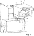
- the electronic component carrier 2 is shown in a second embodiment with an additional function as an intermediate means 13 .
- This intermediate means 13 also includes plug contacts 14 and all the components listed above.
- the additional plug contacts 14 point laterally out of the electronic component carrier housing 6 . There are no differences in the positioning of the two design variants in relation to the arrangement of the lock housing 8 for the electrical component carrier 2 .
- the lock 1 is positioned below the electronic component carrier 2 .
- a part of the lock housing 8 is shown here, with the lock housing 8 containing various components.
- An electromechanical component is indicated in the lock housing 8 .
- This component is an electric motor 9, which has a motor shaft at its front end and contacts at its rear end. When installed, these contacts are connected to the plug-in contacts 12 .
- the installed state is shown as the electric component carrier 2 with its plug-in contacts 12 contacts the electric motor 9 via its contacts.
- the lock housing 8 is provided with a structure, the structure comprising a surface and holding means 10 .
- the surface of the lock housing 8 consists of two bases 7, the bases 7 being intended to facilitate the introduction of the plug contacts 12 and also providing the plug contacts 12 and the modular electrical component carrier 2 with stable support and protection when installed.
- the lock housing 8 is designed with a snap connection as a holding means 10 in this embodiment.
- This holding means 10 holds the electronic component carrier 2 in the installed state by means of a non-positive/positive connection, in that the holding means 10 grip and hold the housing 6 of the electronic component carrier 2 in place.
Description
Die Erfindung betrifft ein Kraftfahrzeugschloss, dass zumindest einen Elektrokomponententräger umfasst, wobei der Elektrokomponententräger als modulares Element ausgebildet ist und mindestens eine Leiterbahn, einen Schalter und optional ein weiteres Bauelement umfasst.The invention relates to a motor vehicle lock that comprises at least one electronic component carrier, the electronic component carrier being designed as a modular element and comprising at least one conductor track, a switch and optionally another component.
Zur Stromversorgung elektrischer Komponenten wie beispielsweise eines Elektromotors und/oder eines Mikroschalters, ist es bekannt, elektrische Leiterbahnen in ein Schlossgehäuse eines Seitentürschlosses für ein Kraftfahrzeug zu integrieren. Ein elektrische Leiterbahnen umfassendes Kunststoffgehäuseteil wird dabei als Elektrokomponententräger (EKT) bezeichnet. Aus dem Elektrokomponententräger weisen zumeist elektrische Kontakte heraus, sodass die elektrischen Bauteile adaptierbar sind.To power electrical components such as an electric motor and/or a microswitch, it is known to integrate electrical conductor tracks into a lock housing of a side door lock for a motor vehicle. A plastic housing part comprising electrical conductor tracks is referred to as an electronic component carrier (EKT). Electrical contacts usually point out of the electronic component carrier, so that the electrical components can be adapted.
Die im Folgenden beschriebenen und bekannten Lösungen beziehen sich beispielhaft auf eingesetzte Elektrokomponententräger und/oder Trägerplatten, die in Kraftfahrzeugschlössern verbaut werden.The known solutions described below relate, for example, to electronic component carriers and/or carrier plates that are installed in motor vehicle locks.
Zum Stand der Technik gehört hierbei eine Trägerplatte, die aus der Druckschrift
Darüber hinaus ist durch die
Bekannt ist ebenfalls aus der
Aus der
Der gattungsbildende Stand der Technik nach den oben genannten Dokumenten stößt dann an Grenzen, wenn es darum geht ein Schlossgehäuse kostengünstig und adaptiv zu gestalten und trotzdem auf komplexe und aufwendig herzustellende Elektrokomponententräger verzichtet werden soll.The generic state of the art according to the above-mentioned documents then reaches its limits when it comes to designing a lock housing in a cost-effective and adaptive manner and nevertheless when complex electronic component carriers that are expensive to produce are to be dispensed with.
Der Erfindung liegt das technische Problem zugrunde, dass der Elektrokomponententräger in der Herstellung ein sehr aufwendiges Bauteil ist. Einerseits weist der Elektrokomponententräger zusätzlich zumeist eine hohe Anzahl an elektrischen Komponenten auf, die zum Teil sehr empfindlich sind und andererseits muss für die Aufnahme und Ausrichtung der Leiterbahnen zumeist auf mehrere Fertigungsschritte zurückgegriffen werden. Die elektrischen Komponenten müssen zumeist in mehreren Arbeitsschritten in das vornehmlich aus Kunststoff gespritzte Schlossgehäuse eingefügt werden. Ein Austausch von defekten elektrischen Komponenten des Schlosses ist in vielen Fällen unmöglich oder sehr aufwendig und teuer. Ebenso muss bei jedem neu entwickelten Schloss ein individuell anzupassender Komponententräger mit elektrischen Elementen erstellt werden. Zur Lösung dieser Aufgabe schlägt die Erfindung einen modularen Elektro-komponententräger für Kraftfahrzeugschlösser vor, der ein separates Gehäuse umfasst und an einer äußeren Oberfläche des Schlossgehäuses des Kraftfahrzeugschlosses befestigbar ist und der Steckkontakte umfasst, die aus dem Elektrokomponententräger herausragen, wobei die Steckkontakte unmittelbar mit einem Motor kontaktiert werden können. Dieser Elektrokomponententräger ist insofern vorteilhaft, da er eine kompakte unabhängige Bauei nheit bildet, die elektrische Komponenten wie beispielsweise Leiterbahnen, Schalter, Kontakte und andere Bauteile umfasst. Somit entfallen elektrische Leiterbahnen sowie andere elektrische Komponenten im Schlossgehäuse. Stattdessen werden die elektrischen Leitungen, Schaltmittel und Elemente in den modularen Elektrokomponententräger eingebaut. Über elektrische Kontakte am modularen Elektrokomponententräger wird dann ein Elektromotor direkt kontaktiert. Ein möglicher Mikroschalter wird in diesem Elektrokomponententräger eingebaut und derart in das Gehäuse vom Elektrokomponententräger und in die Bereiche der zu kontaktierenden Elemente platziert, dass zum Beispiel ein Schalten eines Mikroschalters ermöglicht wird. Ebenso sind die Fertigungskosten für das Schloss sehr gering, weil die Leiterbahnen im Schlossgehäuse entfallen.
Der modulare Elektrokomponententräger kann auch in einer weiteren Ausführungsform mit Stecker und/oder Steckdose ausgebildet sein, so dass ein unmittelbares Kontaktieren erleichtert wird. Darüber hinaus bietet die Möglichkeit der Ausbildung eines Steckers und/oder einer Steckdose ein stabiles Positionieren des modularen Elektrokomponententrägers am Schlossgehäuse. Außerdem ist solch ein zwischengeschalteter Stecker vorteilhaft, wenn es um die Adaptierung verschiedener elektrischer Systeme geht. So ist in dieser Ausführung beispielsweise die Möglichkeit geboten, das man anstatt von einzelnen Leitungsdrähten auch Stecker oder Anschlüsse mit Kabelbäumen anbindet.
Das Gehäuse des Elektrokomponententrägers kann einstückig aus Kunststoff gespritzt und mit Versteifungen ausgebildet sein, so dass empfindliche elektrische Bauteile, wie Leiterbahnen, Stanzgitter, LEDs und Schalter vor äußeren Einflüssen geschützt sind. Fertigungstechnisch werden vornehmlich die Leiterbahnen des Elektrokomponententrägers mit einer Trägerplatte vereinigt und zusammen mit dem Kunststoffgehäuse in einem Spritzgussverfahren gefügt. An diese Trägerplatte, die das Gehäuse des Elektrokomponententrägers bildet können dann elektrische Leiterbahnen und/oder je nach Ausführungsform elektrische Komponenten angeschlossen oder adaptiert werden. Somit ist ein modularer Elektrokomponententräger erzielbar, was wiederum einen Vorteil in Bezug auf Wartungs- und Instandsetzungsarbeiten darstellt, weil anfallende Zeit- und Reparaturkosten durch einen günstigen Austausch minimiert werden. Vorstellbar ist es darüber hinaus auch und stellt ebenfalls einen Vorteil der Erfindung dar, dass der gesamte Elektrokomponententräger austauschbar ist.The invention is based on the technical problem that the electronic component carrier is a very complex component to produce. On the one hand, the electronic component carrier usually also has a large number of electrical components, some of which are very sensitive, and on the other hand, several production steps usually have to be used to accommodate and align the conductor tracks. The electrical components usually have to be inserted in several work steps into the lock housing, which is primarily injection-moulded from plastic. An exchange of defective electrical components of the lock is in impossible or very complicated and expensive in many cases. Likewise, an individually adaptable component carrier with electrical elements must be created for each newly developed lock. To solve this problem, the invention proposes a modular electrical component carrier for motor vehicle locks, which includes a separate housing and can be fastened to an outer surface of the lock housing of the motor vehicle lock and which includes plug contacts that protrude from the electrical component carrier, the plug contacts being directly connected to a motor can be contacted. This electrical component carrier is advantageous in that it forms a compact, self-contained assembly that includes electrical components such as conductor tracks, switches, contacts, and other components. This eliminates the need for electrical conductor tracks and other electrical components in the lock housing. Instead, the electrical lines, switching means and elements are built into the modular electrical component carrier. An electric motor is then contacted directly via electrical contacts on the modular electronic component carrier. A possible microswitch is built into this electronic component carrier and placed in the housing of the electronic component carrier and in the areas of the elements to be contacted in such a way that a microswitch can be switched, for example. Likewise, the production costs for the lock are very low because there are no conductor tracks in the lock housing.
In a further embodiment, the modular electronic component carrier can also be designed with a plug and/or socket, so that direct contacting is facilitated. In addition, the possibility of forming a plug and/or a socket offers stable positioning of the modular electronic component carrier on the lock housing. Such an intermediate connector is also advantageous when it comes to adapting different electrical systems. For example, this version offers the option of connecting plugs or connections with cable harnesses instead of individual wires.
The housing of the electronic component carrier can be injection-molded in one piece from plastic and designed with reinforcements, so that sensitive electrical components, such as conductor tracks, pressed screens, LEDs and switches are protected from external influences. In terms of manufacturing technology, the conductor tracks of the electronic component carrier are primarily combined with a carrier plate and joined together with the plastic housing in an injection molding process. Electrical conductor tracks and/or electrical components, depending on the embodiment, can then be connected or adapted to this carrier plate, which forms the housing of the electronic component carrier. A modular electronic component carrier can thus be achieved, which in turn represents an advantage with regard to maintenance and repair work, because the time and repair costs incurred are minimized by a cheap replacement. It is also conceivable and also represents an advantage of the invention that the entire electronic component carrier is exchangeable.
Die äußere Oberfläche des Kraftfahrzeugschlosses ist entsprechend zugänglich ausgebildet, so dass an die äußere Oberfläche ein Elektrokomponententräger adaptierbar ist. Insbesondere kann so eine Oberfläche aus zwei Sockeln bestehen, die aus dem Gehäuse des Elektrokomponententrägers heraus ragen. Diese Sockel bieten durch ihre Ausbildung entsprechend angepasst an den Elektrokomponententräger eine Abstützung, wodurch der Elektrokomponententräger eine verbesserte Stabilität erfährt. Gleichzeitig bilden die Sockel Führungen für zum Beispiel Steckkontakte. Die Abstützung erfolgt dann im Rahmen einen Formschlusses zwischen Elektrokomponententräger und dem Gehäuse des Kraftfahrzeugschlosses.The outer surface of the motor vehicle lock is made accessible so that an electronic component carrier can be adapted to the outer surface. In particular, such a surface can consist of two bases that protrude from the housing of the electronic component carrier. Due to their design, these bases offer support that is appropriately adapted to the electronic component carrier, as a result of which the electronic component carrier experiences improved stability. At the same time, the bases form guides for plug contacts, for example. The support then takes place within the framework of a form fit between the electronic component carrier and the housing of the motor vehicle lock.
Des Weiteren lässt sich ein Vorteil der Erfindung dadurch herstellen, dass der Elektro-komponententräger mit einer Leiterbahn und einem Schaltmittel und optional einem weiteren elektrischen Bauelement einstückig ausgebildet ist. Es ist beispielsweise eine Trägerplatte vorstellbar, auf der mehrere elektrische Komponenten durch beispielsweise Anlöten angebracht sind. Das Gehäuse kann dann in einem Spritzgussverfahren mit einem Kunststoff gefüllt sein, so dass die elektrischen Komponenten zum Beispiel vor Feuchtigkeit und Erschütterungen geschützt sind. Hierdurch wird eine untrennbare Einheit gebildet, die erfindungsgemäß als einstückiger Aufbau definiert wird. Die empfindlichen elektrischen Komponenten sind dank des Gehäuses und dem Verbund des Aufbaus optimal vor äußeren Einwirkungen wie Stößen geschützt und erhalten dank der festen Verbindung eine Stabilität und/oder Steifigkeit, wodurch letztlich die Lebensdauer des Elektrokomponententrägers verlängert wird.Furthermore, an advantage of the invention can be produced in that the electronic component carrier is designed in one piece with a conductor track and a switching means and optionally a further electrical component. For example, a carrier plate is conceivable, on which several electrical components are attached by soldering, for example. The housing can then in one Be filled with a plastic injection molding process, so that the electrical components are protected from moisture and shock, for example. This forms an inseparable unit, which is defined according to the invention as a one-piece structure. Thanks to the housing and the composite structure, the sensitive electrical components are optimally protected against external influences such as impacts and, thanks to the fixed connection, are stable and/or rigid, which ultimately extends the service life of the electronic component carrier.
Erfindungsgemäß ist ein Schaltmittel im Elektrokomponententräger derart angeordnet, dass das Schaltmittel aus dem Gehäuse des Elektrokomponententrägers hinaus ragt und das Gehäuse des Kraftfahrzeugschlosses hinein reicht, so dass das Schaltmittel mit mechanischen Bauteilen zusammenwirkt. Bei dem Schaltmittel kann es sich beispielsweise um einen Mikroschalter handeln, der mit mechanischen Bauteilen im Schloss wie zum Beispiel einer Drehfalle oder einem anderen Hebel in Kontakt steht. Somit ist auch hier ein unmittelbares Erfassen eines Zustands und/oder einer Lage eines bewegten Bauteils des Kraftfahrzeugschlosses ermöglicht.According to the invention, a switching means is arranged in the electronic component carrier in such a way that the switching means protrudes from the housing of the electronic component carrier and the housing of the motor vehicle lock extends into it, so that the switching means interacts with mechanical components. The switching means can be a microswitch, for example, which is in contact with mechanical components in the lock, such as a rotary latch or another lever. Thus, a direct detection of a state and/or a position of a moving component of the motor vehicle lock is also made possible here.
Ebenso kann es von Vorteil sein, dass der Elektrokomponententräger mit wenigstens einem Haltemittel des Gehäuses des Kraftfahrzeugschlosses zusammenwirkt. Dadurch wird ein unerwünschtes Lösen des Elektrokomponententrägers vom Kraftfahrzeugschlossgehäuse verhindert. Durch das eine oder die zwei oder mehreren Haltemittel ist der Elektrokomponententräger am Kraftfahrzeugschlossgehäuse fixierbar. Eine sichere Übertragung elektrischer Signale kann unter Verhinderung von Wackelkontakten realisiert werden. Unter Haltemittel werden zum Beispiel formschlüssige Verbindungen in Form von Rastnasen, Haken oder Klammern verstanden, die aus separaten Elementen oder einstückig mit dem Elektrokomponententräger und/oder dem Gehäuse des Kraftfahrzeugschlosses ausgebildet sind. Darüber hinaus ist es erfindungsgemäß vorstellbar den Elektrokomponententräger mit dem Gehäuse des Kraftfahrzeugschlosses zu verschrauben oder zu vernieten. Denkbar sind auch Klebstoffe oder Schweißnähte, die vor der Erstarrung beziehungsweise Abkühlung oder Trocknung einen flüssigen Zustand aufweisen.It can also be advantageous that the electronic component carrier interacts with at least one holding means of the housing of the motor vehicle lock. This prevents the electrical component carrier from becoming undesirably detached from the motor vehicle lock housing. The electronic component carrier can be fixed to the motor vehicle lock housing by the one or the two or more holding means. Safe transmission of electrical signals can be implemented while preventing loose contacts. Holding means are understood to mean, for example, form-fitting connections in the form of latching lugs, hooks or clips, which are formed from separate elements or in one piece with the electronic component carrier and/or the housing of the motor vehicle lock. In addition, it is conceivable according to the invention to close the electronic component carrier with the housing of the motor vehicle lock screw or rivet. Adhesives or weld seams that are in a liquid state before solidification or cooling or drying are also conceivable.
Darüber hinaus kann sich ein Vorteil daraus ergeben, dass das Haltemittel mit dem Elektrokomponententräger aus einer kraftschlüssigen und/oder formschlüssigen Verbindung besteht. Unter einer kraftschlüssigen Verbindung kann man sich Klemmen, Keile oder Schraubverbindungen vorstellen, die den Elektrokomponententräger mit dem Schlossgehäuse verbinden. Schraubenverbindungen zählen ebenfalls zusammen mit den Niet- und Stiftverbindungen zu den formschlüssigen Verbindungen. Die physikalischen Wirkprinzipien dieser Verbindungsarten können individuelle Vorteile bieten. So sind beispielsweise Schraubverbindungen gut lösbar und auf viele Beanspruchungsarten wie Torsion, Zug, Scherung und Biegung auslegbar. Bei Stift- und Bolzenverbindungen wird dagegen ein unbeabsichtigtes Losdrehen verhindert.In addition, an advantage can result from the fact that the holding means consists of a non-positive and/or positive connection with the electronic component carrier. A non-positive connection can be thought of as clamps, wedges or screw connections that connect the electronic component carrier to the lock housing. Screw connections, together with rivet and pin connections, are also positive connections. The physical working principles of these connection types can offer individual advantages. For example, screw connections are easy to detach and can be designed for many types of stress such as torsion, tension, shear and bending. In the case of pin and bolt connections, on the other hand, unintentional loosening is prevented.
Insbesondere ergeben sich Vorteile daraus, dass die Haltemittel als Clip-, Schnapp- und/oder Rastverbindungen, und/oder Schraubenverbindungen, und/oder Bolzen- und/oder Nietverbindungen ausgebildet sind. Clip-, Schnapp- oder Rastverbindungen sind günstig, weil sie unmittelbar als Bereiche beziehungsweise Elemente des Schlossgehäuses ausgebildet sein können. Sie werden somit im Herstellungsvorgang des Schlossgehäuses wie beispielsweise beim Kunststoffspritzguss ausgebildet. Daraus ergeben sich Zeit- und Kostenvorteile bezüglicher der Fertigung.In particular, advantages result from the fact that the holding means are designed as clip, snap and/or latching connections and/or screw connections and/or bolt and/or rivet connections. Clip, snap or latch connections are favorable because they can be designed directly as areas or elements of the lock housing. You are thus formed in the manufacturing process of the lock housing such as plastic injection molding. This results in time and cost advantages with regard to production.
Optional kann auch das Gehäuse des Elektrokomponententrägers mit Clip-, Schnapp- oder Rasthilfsmitteln ausgebildet sein. Schrauben bieten wie bereits erwähnt Vorteile bezüglich hoher Belastbarkeit und vor allem flexibler Montage. Bolzen und Stiftverbindung sind Verbindungsmittel, die die höchsten Beanspruchungen verkraften können. In der vorgestellten Erfindung sind die Hilfsmittel als Klemmen beziehungsweise Schnappverbindungen ausgebildet, die einen Teil des Schlossgehäuses bilden und das Elektrokomponentengehäuse am Umfang umgreifen und festhalten. Ein Verbindungspartner ist entsprechend der Form des jeweiligen Verbindungspartners ausgebildet um mit seinem Verbindungspartner optimal zusammenzuwirken.Optionally, the housing of the electronic component carrier can also be designed with clip, snap or latching aids. As already mentioned, screws offer advantages in terms of high load capacity and, above all, flexible assembly. Bolts and pin connections are fasteners that can withstand the highest loads. In the presented invention, the aids are designed as clamps or snap connections that form part of the lock housing and the Grasp the circumference of the electronic component housing and hold it. A connection partner is designed according to the shape of the respective connection partner in order to interact optimally with its connection partner.
Darüber hinaus ist es von Vorteil, dass das Gehäuse des Elektrokomponententrägers aus Kunststoff ausgebildet ist. Die Materialkosten sind aufgrund des Kunststoffwerkstoffs gering und die Trägerplatte mit elektrischen Komponenten kann in einem Spritzgussvorgang gut in das Gehäuse eingefügt oder integriert werden. Außerdem weist das Gehäuse des Elektrokomponententrägers durch den Kunststoff ein geringeres Gewicht auf, als ein vergleichbares metallisches Werkstoffgehäuse. Des Weiteren ist das Kunststoffgehäuse soweit vorteilhaft, weil der Kunststoff in der Formungsphase mit Haltemitteln und anderen nützlichen Elementen ausgebildet werden kann.
Außerdem umfasst der Elektrokomponententräger zumindest einen Anschluss, insbesondere einen Steckkontakt für eine Elektronik und/oder eine Steuerung. Eine gewisse Anzahl an Anschlüssen am Elektrokomponententräger bietet eine Vielzahl an Möglichkeiten beziehungsweise Schnittstellen, um andere elektrische Einheiten wie zum Beispiel eine Steuereinheit anzuschließen. Diese Schnittstellen sind als Steckkontakte ausgebildet, die mit anderen Kontakten kontaktieren. Dadurch können Steckkontakte am Schlossgehäuse selbst entfallen, was zu einer Fertigungskostenreduzierung führt.
Insbesondere ergibt sich ein Vorteil dadurch, dass es sich bei den Steckkontakten des Elektrokomponententrägers vor allem um Kontaktfahnen handelt, die aus dem Elektrokomponententräger herausrage. Dabei können die Kontaktfahnen zum Beispiel unmittelbar mit einer elektrischen Komponente im Kraftfahrzeugschloss, wie beispielsweise einem Motor, kontaktiert werden. Die Steckkontakte erstrecken sich dabei ausgehend von dem Elektrokomponententräger bis in das Kraftfahrzeugschloss hinein, so dass die elektrischen Komponenten unmittelbar kontaktiert werden können. Aufgrund der Erstreckung der Steckkontakte, besitzt der Elektrokomponententräger eine hohe Reichweite und erreicht somit sicher Komponenten im Kraftfahrzeugschloss wie beispielsweise einen Elektromotor. Die Kontaktfahnen können durch Sockel des Schlossgehäuses in das Schlossgehäuse hinein reichen, wobei die Sockel dem Elektrokomponententräger Stabilität bieten. Ebenso schützen die Sockel die Kontaktfahnen vor äußeren Einflüssen wie Beschädigung oder Korrosion. Das Kraftfahrzeugschlossgehäuse kann dabei ohne Leiterbahnen ausgebildet werden, was zu Kosteneinsparungen maßgeblich beiträgt, da die notwendigen Leiterbahnen bereits im Elektrokomponententräger ausgebildet sind.In addition, it is advantageous that the housing of the electronic component carrier is made of plastic. The material costs are low due to the plastic material and the carrier plate with electrical components can be easily inserted or integrated into the housing in an injection molding process. In addition, the housing of the electronic component carrier has a lower weight than a comparable metallic material housing due to the plastic. Furthermore, the plastic housing is advantageous insofar as the plastic can be formed with holding means and other useful elements at the molding stage.
In addition, the electronic component carrier includes at least one connection, in particular a plug-in contact for electronics and/or a controller. A certain number of connections on the electrical component carrier offers a variety of options or interfaces for connecting other electrical units such as a control unit. These interfaces are designed as plug contacts that make contact with other contacts. As a result, plug-in contacts on the lock housing itself can be omitted, which leads to a reduction in production costs.
In particular, there is an advantage in that the plug contacts of the electronic component carrier are primarily contact lugs that protrude from the electronic component carrier. In this case, the contact lugs can, for example, be contacted directly with an electrical component in the motor vehicle lock, such as an engine. Starting from the electrical component carrier, the plug contacts extend into the motor vehicle lock, so that contact can be made directly with the electrical components. Due to the extent of the plug contacts, the electronic component carrier has a long range and thus safely reaches components in the motor vehicle lock such as for example an electric motor. The contact lugs can extend into the lock housing through the base of the lock housing, with the base offering stability to the electronic component carrier. The sockets also protect the contact lugs from external influences such as damage or corrosion. The motor vehicle lock housing can be designed without conductors, which contributes significantly to cost savings, since the necessary conductors are already formed in the electronic component carrier.
Im Folgenden wird die Erfindung anhand von Zeichnungen näher erläutert. Es zeigen:
- Fig. 1
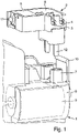
- eine dreidimensionale Ansicht eines Elektrokomponententrägers in einer ersten Ausführungsform, sowie einen Teil des Schlossgehäuses vor dem Einbau des Elektrokomponententrägers,
- Fig. 2
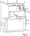
- eine dreidimensionale Ansicht des Elektrokomponententrägers in einer ersten Ausführungsform, sowie einen Teil des Schlossgehäuses im Einbauzustand des Elektrokomponententrägers,
- Fig. 3
- eine dreidimensionale Ansicht einer weiteren Ausführungsform eines Elektrokomponententrägers, sowie einen Teil des Schlossgehäuses vor dem Einbau des Elektrokomponententrägers und
- Fig. 4
- eine dreidimensionale Ansicht des Elektrokomponententrägers in einer zweiten Ausführungsform, sowie einen Teil des Schlossgehäuses im Einbauzustand des Elektrokomponententrägers.
- 1
- a three-dimensional view of an electronic component carrier in a first embodiment, and a part of the lock housing before the installation of the electronic component carrier,
- 2
- a three-dimensional view of the electronic component carrier in a first embodiment, and a part of the lock housing in the installed state of the electronic component carrier,
- 3
- a three-dimensional view of a further embodiment of an electronic component carrier, and a part of the lock housing before the installation of the electronic component carrier and
- 4
- a three-dimensional view of the electronic component carrier in a second embodiment, and a part of the lock housing in the installed state of the electronic component carrier.
Der modulare Elektrokomponententräger 2 weist in allen Figuren ein entsprechend kompakt ausgebildetes Gehäuse 6 auf. Das Gehäuse 6 besteh aus Kunststoff und weist einen ausreichend großen Bauraum auf, so dass elektrische Komponenten eingesetzt werden können. In allen Zeichnungen ist dieser Bauraum offen dargestellt, jedoch kann der Bauraum auch eine Abdeckung zum Schutz später enthalten oder mittels eines Vergießens verschlossen sein. Diese möglichen Abdeckungen sind nicht in den Zeichnungen dargestellt. Im Bauraum sind ein Schalter 5 mit elektrischem Kontakt 11 sowie beispielhaft einige elektrische Leiterbahnen 3 und 4 gezeigt. Der Elektrokomponententräger 2 weist Steckkontakte 12 auf, die aus einer Verlängerung des Elektrokomponententrägers 2 herausragen. Dabei weisen die Steckkontakte 12 in Richtung des Schlossgehäuses 8 beziehungsweise einer Oberfläche 7 des Schlossgehäuses 8 des Kraftfahrzeuges.The modular
In den
Unterhalb des Elektrokomponententrägers 2 ist das Schloss 1 positioniert. Hierbei wird ein Teil des Schlossgehäuses 8 gezeigt, wobei das Schlossgehäuse 8 diverse Bauelemente beinhaltet. Im Schlossgehäuse 8 ist ein elektromechanisches Bauteil angedeutet. Bei diesem Bauteil handelt es sich um einen Elektromotor 9, der an seinem vorderen Ende eine Motorwelle und an seinem hinteren Ende Kontakte aufweist. Diese Kontakte stehen im eingebauten Zustand mit den Steckkontakten 12 in Verbindung. In den
Darüber hinaus ist das Schlossgehäuse 8 mit einem Aufbau versehen, wobei der Aufbau eine Oberfläche sowie Haltemittel 10 umfasst. In diesem Ausführungsbeispiel besteht die Oberfläche des Schlossgehäuses 8 aus zwei Sockeln 7, wobei die Sockel 7 die Einführung der Steckkontakte 12 erleichtern sollen und zusätzlich den Steckkontakten 12 sowie dem modularen Elektrokomponententräger 2 eine stabile Abstützung und Schutz im eingebauten Zustand bieten.In addition, the
Um ein Loslösen des Elektrokomponententrägers 2 vom Schloss 1 zu verhindern, ist das Schlossgehäuse 8 in dieser Ausführung mit einer Schnappverbindung als Haltemittel 10 ausgebildet. Dieses Haltemittel 10 hält den Elektrokomponententräger 2 im eingebauten Zustand durch eine kraft-/formschlüssige Verbindung fest, indem die Haltemittel 10 das Gehäuse 6 des Elektrokomponententrägers 2 umgreifen und festhalten.In order to prevent the
Claims (7)
- Motor vehicle latch (1) comprising at least one electrical component carrier (2), the electrical component carrier (2) being designed as a modular element and comprising at least one conductor track (3), (4) and at least one switching means (5) and optionally a further electrical component and a separate housing (6), and being able to be fastened to an outer surface (7) of the latch housing (8) of the motor vehicle latch (1), characterized In that the electrical component carrier (2) comprises plug-in contacts (12) which protrude from the electrical component carrier (2), it being possible for the plug-In contacts (12) to be contacted directly with a motor (9) of the motor vehicle latch (1), at least one switching means (5) of the electrical component carrier (2) protruding into the housing (8) of the motor vehicle latch (1) and interacting with mechanical components.
- Motor vehicle latch (1) according to claim 1, characterized in that the electrical component carrier (2) is provided with electrical components, in particular a conductor track (3), (4) and/or a switching means (5) and/or a further electrical component, and is formed as a single piece.
- Motor vehicle latch (1) according to either claim 1 or claim 2, characterized in that the electrical component carrier (2) interacts with holding means (10) of the housing (8) of the motor vehicle latch (1).
- Motor vehicle latch (1) according to claim 3, characterized In that the holding means (10) together with the electrical component carrier (2) consists of a frictional and/or form-fitting connection.
- Motor vehicle latch (1) according to claim 4, characterized in that the holding means (10) is formed from at least one clip, snap and/or latching connection and/or screw connection and/or bolt connection and/or rivet connection.
- Motor vehicle latch (1) according to any of claims 1 to 5, characterized in that the housing (6) of the electrical component carrier (2) consists of a plastics material.
- Motor vehicle latch (1) according to claims 1 to 6, characterized in that the electrical component carrier (2) comprises at least one connection, in particular a plug-in contact (12), (14), for electronics and/or a controller.
Applications Claiming Priority (2)
| Application Number | Priority Date | Filing Date | Title |
|---|---|---|---|
| DE102014000294.2A DE102014000294A1 (en) | 2014-01-15 | 2014-01-15 | Side door lock for a motor vehicle |
| PCT/DE2015/100022 WO2015106761A1 (en) | 2014-01-15 | 2015-01-15 | Side-door lock for a motor vehicle |
Publications (3)
| Publication Number | Publication Date |
|---|---|
| EP3094800A1 EP3094800A1 (en) | 2016-11-23 |
| EP3094800B1 EP3094800B1 (en) | 2018-09-26 |
| EP3094800B2 true EP3094800B2 (en) | 2022-05-04 |
Family
ID=52682585
Family Applications (1)
| Application Number | Title | Priority Date | Filing Date |
|---|---|---|---|
| EP15709823.7A Active EP3094800B2 (en) | 2014-01-15 | 2015-01-15 | Side-door lock for a motor vehicle |
Country Status (5)
| Country | Link |
|---|---|
| US (2) | US10947759B2 (en) |
| EP (1) | EP3094800B2 (en) |
| CN (1) | CN105992855B (en) |
| DE (2) | DE102014000294A1 (en) |
| WO (1) | WO2015106761A1 (en) |
Families Citing this family (6)
| Publication number | Priority date | Publication date | Assignee | Title |
|---|---|---|---|---|
| US11247595B2 (en) * | 2016-05-13 | 2022-02-15 | Kiekert Ag | Latching device |
| DE102016116606A1 (en) * | 2016-09-06 | 2018-03-08 | Kiekert Ag | Component carrier for electrical / electronic components for mounting in a motor vehicle door lock |
| JP7310881B2 (en) * | 2019-03-27 | 2023-07-19 | 三井金属アクト株式会社 | VEHICLE DOOR LOCK DEVICE AND METHOD OF MANUFACTURING VEHICLE DOOR LOCK DEVICE |
| DE102022107938A1 (en) | 2022-04-04 | 2023-10-05 | Kiekert Aktiengesellschaft | Drive unit for automotive technical applications |
| DE102022115496A1 (en) | 2022-06-22 | 2023-12-28 | Kiekert Aktiengesellschaft | Motor vehicle lock assembly and method for its production |
| DE102022116938A1 (en) | 2022-07-07 | 2024-01-18 | Kiekert Aktiengesellschaft | Motor vehicle lock |
Citations (1)
| Publication number | Priority date | Publication date | Assignee | Title |
|---|---|---|---|---|
| JPH0826710B2 (en) † | 1990-07-25 | 1996-03-13 | 日本電装株式会社 | Motor built-in device |
Family Cites Families (30)
| Publication number | Priority date | Publication date | Assignee | Title |
|---|---|---|---|---|
| CA1326502C (en) * | 1988-03-11 | 1994-01-25 | Wolfgang Thau | Latch mechanism, components thereof and process of manufacture for components thereof |
| US4894018A (en) * | 1988-08-08 | 1990-01-16 | General Motors Corporation | Low profile electrical connector |
| US5360351A (en) * | 1990-04-04 | 1994-11-01 | Rockwell International Corporation | Housing for the interface between a motor vehicle lock, its actuator and the electrical connection harness of the vehicle |
| DE19702205B4 (en) * | 1997-01-23 | 2004-12-23 | Kiekert Ag | Motor vehicle door lock, in particular for motor vehicles with a central locking and anti-theft device |
| JP3543207B2 (en) * | 1997-08-27 | 2004-07-14 | 株式会社大井製作所 | Automotive door lock device with detection switch |
| DE19945103C1 (en) | 1999-09-21 | 2001-05-31 | Valeo Gmbh & Co Schliessyst Kg | Door module |
| FR2803113B1 (en) * | 1999-12-22 | 2002-05-17 | Valeo Securite Habitacle | ELECTRIC MODULE FOR A MOTOR VEHICLE LOCK, AND METHOD FOR THE PRODUCTION THEREOF |
| DE10100010B4 (en) * | 2001-01-02 | 2005-05-12 | Brose Schließsysteme GmbH & Co.KG | Motor vehicle door lock, designed as an electric lock, and method for assembling a motor vehicle door lock designed as an electric lock |
| JP2002332767A (en) * | 2001-05-09 | 2002-11-22 | Harada Ind Co Ltd | Switch box structure for vehicular door locking device |
| DE10139356A1 (en) | 2001-08-17 | 2003-02-27 | Kiekert Ag | Electrical component arrangement |
| DE10336049A1 (en) * | 2003-08-01 | 2005-02-17 | Kiekert Ag | Motor vehicle door lock |
| FR2878089B1 (en) * | 2004-11-12 | 2007-03-02 | Arvinmeritor Light Vehicle Sys | ELECTRIC LOCK MOTOR |
| JP4576321B2 (en) * | 2005-11-15 | 2010-11-04 | アスモ株式会社 | Actuator |
| DE102006017830A1 (en) * | 2006-04-13 | 2007-10-18 | Kiekert Ag | Device for a motor vehicle lock with component carrier |
| DE202006009247U1 (en) | 2006-06-09 | 2006-08-24 | Kiekert Ag | Automotive door lock has plastic housing with electrical adaptor and connector to internal components |
| DE202006011116U1 (en) | 2006-07-17 | 2006-09-14 | Kiekert Ag | Base plate with actuator for automotive door lock consists of a one-piece injection molded component |
| DE102006037159B4 (en) | 2006-08-02 | 2012-03-29 | Oechsler Ag | Component carrier and method of manufacturing an electrical assembly by wiring its components |
| JP4834856B2 (en) * | 2007-06-15 | 2011-12-14 | 三井金属アクト株式会社 | Latch unit for vehicle |
| DE202008015696U1 (en) | 2008-11-27 | 2010-04-15 | Kiekert Ag | Component carrier for essentially electrical components |
| DE202009004984U1 (en) * | 2009-07-03 | 2009-08-27 | Kiekert Ag | Motor vehicle lock consisting of mechanical and electrical, electromotive and / or electronic components |
| DE102009053384A1 (en) | 2009-11-14 | 2011-05-19 | Kiekert Ag | Method for producing a motor vehicle door lock and associated motor vehicle door lock |
| DE202010004424U1 (en) | 2010-03-31 | 2010-07-29 | Kiekert Ag | Motor vehicle door lock |
| JP5627388B2 (en) * | 2010-10-20 | 2014-11-19 | 株式会社ユーシン | Door lock device |
| CN202658989U (en) * | 2012-05-15 | 2013-01-09 | 盈佳科技(长春)有限公司 | Fastener structure |
| US9284758B2 (en) | 2012-06-28 | 2016-03-15 | Mitsui Kinzoku Act Corporation | Operating device for a vehicle door latch |
| DE102012211759A1 (en) | 2012-07-05 | 2014-01-09 | Kiekert Ag | Electro component carrier with self-sealing contact |
| DE102012211756A1 (en) | 2012-07-05 | 2014-01-09 | Kiekert Ag | Electric component carrier for a motor vehicle together with production |
| DE202012105072U1 (en) * | 2012-12-27 | 2014-03-28 | Kiekert Ag | Component carrier for electrical / electronic components |
| DE202012105073U1 (en) * | 2012-12-27 | 2014-03-31 | Kiekert Ag | component support |
| DE102013007404A1 (en) * | 2013-04-30 | 2014-10-30 | BROSE SCHLIEßSYSTEME GMBH & CO. KG | Electric motor vehicle component |
-
2014
- 2014-01-15 DE DE102014000294.2A patent/DE102014000294A1/en not_active Withdrawn
-
2015
- 2015-01-15 CN CN201580008202.3A patent/CN105992855B/en active Active
- 2015-01-15 DE DE202015009935.1U patent/DE202015009935U1/en active Active
- 2015-01-15 US US15/111,923 patent/US10947759B2/en active Active
- 2015-01-15 EP EP15709823.7A patent/EP3094800B2/en active Active
- 2015-01-15 WO PCT/DE2015/100022 patent/WO2015106761A1/en active Application Filing
-
2021
- 2021-02-11 US US17/174,154 patent/US11834873B2/en active Active
Patent Citations (1)
| Publication number | Priority date | Publication date | Assignee | Title |
|---|---|---|---|---|
| JPH0826710B2 (en) † | 1990-07-25 | 1996-03-13 | 日本電装株式会社 | Motor built-in device |
Also Published As
| Publication number | Publication date |
|---|---|
| DE102014000294A1 (en) | 2015-07-16 |
| EP3094800A1 (en) | 2016-11-23 |
| DE202015009935U1 (en) | 2021-08-26 |
| US20160356066A1 (en) | 2016-12-08 |
| CN105992855A (en) | 2016-10-05 |
| EP3094800B1 (en) | 2018-09-26 |
| WO2015106761A1 (en) | 2015-07-23 |
| US10947759B2 (en) | 2021-03-16 |
| US11834873B2 (en) | 2023-12-05 |
| US20210164273A1 (en) | 2021-06-03 |
| CN105992855B (en) | 2018-09-11 |
Similar Documents
| Publication | Publication Date | Title |
|---|---|---|
| EP3094800B2 (en) | Side-door lock for a motor vehicle | |
| EP3051551B1 (en) | Module assembly with at least one base module | |
| WO2008037529A1 (en) | Connection system comprising an external cable guide on wiper motor housings | |
| DE102010025086A1 (en) | Method for the electrical contacting of an electrical assembly for a motor vehicle with at least one plug | |
| EP3257121B1 (en) | Arrangement of multiple latching feet for an assembly | |
| DE202010004408U1 (en) | Sequence of connection modules | |
| WO2007118451A1 (en) | Device for a motor vehicle lock with component mounting | |
| EP2091113B1 (en) | Connection system for light strips or lights | |
| DE102010015449A1 (en) | Mounting arrangement for electrical appliances | |
| WO2009118028A1 (en) | Electric modular system comprising a multi-functional field bus module | |
| EP3076504B1 (en) | Adapter device for a busbar system | |
| EP2211599B1 (en) | Assembly and assembly holder | |
| EP1978600B1 (en) | Board assembly | |
| DE102010029374A1 (en) | Power electronics arrangement for use in high-voltage onboard network architecture of fuel cell vehicle, has electrical terminals whose part is located on housing and on cables for attaching cables in common longitudinal extension | |
| DE19724254A1 (en) | Central electrical arrangement esp for motor vehicle | |
| DE102010024341A1 (en) | Connecting device and distribution cabinet arrangement | |
| DE102014015658A1 (en) | electronics assembly | |
| DE102007018175A1 (en) | Power splitter for current distribution within main power supply of motor vehicle, has fuses firmly connected with wiring harness and its cables in undetachable manner in form of crimping connection and directly connected with splitter bar | |
| EP1029743B1 (en) | Vehicle modular electrical distribution centre | |
| EP2893785B1 (en) | Arrangement of an electric control device on a circuit board | |
| EP2852725B1 (en) | Operating element for a motor vehicle | |
| DE10316384A1 (en) | Contact adapter for contacting an antenna structure of a vehicle | |
| EP2083435B1 (en) | Connection unit for fuses | |
| DE102015122659A1 (en) | Electrical circuit | |
| DE102011122499B4 (en) | Plug holder for a truck |
Legal Events
| Date | Code | Title | Description |
|---|---|---|---|
| PUAI | Public reference made under article 153(3) epc to a published international application that has entered the european phase |
Free format text: ORIGINAL CODE: 0009012 |
|
| 17P | Request for examination filed |
Effective date: 20160721 |
|
| AK | Designated contracting states |
Kind code of ref document: A1 Designated state(s): AL AT BE BG CH CY CZ DE DK EE ES FI FR GB GR HR HU IE IS IT LI LT LU LV MC MK MT NL NO PL PT RO RS SE SI SK SM TR |
|
| AX | Request for extension of the european patent |
Extension state: BA ME |
|
| DAX | Request for extension of the european patent (deleted) | ||
| GRAP | Despatch of communication of intention to grant a patent |
Free format text: ORIGINAL CODE: EPIDOSNIGR1 |
|
| STAA | Information on the status of an ep patent application or granted ep patent |
Free format text: STATUS: GRANT OF PATENT IS INTENDED |
|
| INTG | Intention to grant announced |
Effective date: 20180409 |
|
| GRAS | Grant fee paid |
Free format text: ORIGINAL CODE: EPIDOSNIGR3 |
|
| GRAA | (expected) grant |
Free format text: ORIGINAL CODE: 0009210 |
|
| STAA | Information on the status of an ep patent application or granted ep patent |
Free format text: STATUS: THE PATENT HAS BEEN GRANTED |
|
| AK | Designated contracting states |
Kind code of ref document: B1 Designated state(s): AL AT BE BG CH CY CZ DE DK EE ES FI FR GB GR HR HU IE IS IT LI LT LU LV MC MK MT NL NO PL PT RO RS SE SI SK SM TR |
|
| REG | Reference to a national code |
Ref country code: GB Ref legal event code: FG4D Free format text: NOT ENGLISH |
|
| REG | Reference to a national code |
Ref country code: CH Ref legal event code: EP |
|
| REG | Reference to a national code |
Ref country code: AT Ref legal event code: REF Ref document number: 1046220 Country of ref document: AT Kind code of ref document: T Effective date: 20181015 |
|
| REG | Reference to a national code |
Ref country code: IE Ref legal event code: FG4D Free format text: LANGUAGE OF EP DOCUMENT: GERMAN |
|
| REG | Reference to a national code |
Ref country code: DE Ref legal event code: R096 Ref document number: 502015006079 Country of ref document: DE |
|
| REG | Reference to a national code |
Ref country code: NL Ref legal event code: MP Effective date: 20180926 |
|
| PG25 | Lapsed in a contracting state [announced via postgrant information from national office to epo] |
Ref country code: LT Free format text: LAPSE BECAUSE OF FAILURE TO SUBMIT A TRANSLATION OF THE DESCRIPTION OR TO PAY THE FEE WITHIN THE PRESCRIBED TIME-LIMIT Effective date: 20180926 Ref country code: BG Free format text: LAPSE BECAUSE OF FAILURE TO SUBMIT A TRANSLATION OF THE DESCRIPTION OR TO PAY THE FEE WITHIN THE PRESCRIBED TIME-LIMIT Effective date: 20181226 Ref country code: SE Free format text: LAPSE BECAUSE OF FAILURE TO SUBMIT A TRANSLATION OF THE DESCRIPTION OR TO PAY THE FEE WITHIN THE PRESCRIBED TIME-LIMIT Effective date: 20180926 Ref country code: NO Free format text: LAPSE BECAUSE OF FAILURE TO SUBMIT A TRANSLATION OF THE DESCRIPTION OR TO PAY THE FEE WITHIN THE PRESCRIBED TIME-LIMIT Effective date: 20181226 Ref country code: FI Free format text: LAPSE BECAUSE OF FAILURE TO SUBMIT A TRANSLATION OF THE DESCRIPTION OR TO PAY THE FEE WITHIN THE PRESCRIBED TIME-LIMIT Effective date: 20180926 Ref country code: RS Free format text: LAPSE BECAUSE OF FAILURE TO SUBMIT A TRANSLATION OF THE DESCRIPTION OR TO PAY THE FEE WITHIN THE PRESCRIBED TIME-LIMIT Effective date: 20180926 Ref country code: GR Free format text: LAPSE BECAUSE OF FAILURE TO SUBMIT A TRANSLATION OF THE DESCRIPTION OR TO PAY THE FEE WITHIN THE PRESCRIBED TIME-LIMIT Effective date: 20181227 |
|
| REG | Reference to a national code |
Ref country code: LT Ref legal event code: MG4D |
|
| PG25 | Lapsed in a contracting state [announced via postgrant information from national office to epo] |
Ref country code: LV Free format text: LAPSE BECAUSE OF FAILURE TO SUBMIT A TRANSLATION OF THE DESCRIPTION OR TO PAY THE FEE WITHIN THE PRESCRIBED TIME-LIMIT Effective date: 20180926 Ref country code: HR Free format text: LAPSE BECAUSE OF FAILURE TO SUBMIT A TRANSLATION OF THE DESCRIPTION OR TO PAY THE FEE WITHIN THE PRESCRIBED TIME-LIMIT Effective date: 20180926 Ref country code: AL Free format text: LAPSE BECAUSE OF FAILURE TO SUBMIT A TRANSLATION OF THE DESCRIPTION OR TO PAY THE FEE WITHIN THE PRESCRIBED TIME-LIMIT Effective date: 20180926 |
|
| PG25 | Lapsed in a contracting state [announced via postgrant information from national office to epo] |
Ref country code: ES Free format text: LAPSE BECAUSE OF FAILURE TO SUBMIT A TRANSLATION OF THE DESCRIPTION OR TO PAY THE FEE WITHIN THE PRESCRIBED TIME-LIMIT Effective date: 20180926 Ref country code: NL Free format text: LAPSE BECAUSE OF FAILURE TO SUBMIT A TRANSLATION OF THE DESCRIPTION OR TO PAY THE FEE WITHIN THE PRESCRIBED TIME-LIMIT Effective date: 20180926 Ref country code: EE Free format text: LAPSE BECAUSE OF FAILURE TO SUBMIT A TRANSLATION OF THE DESCRIPTION OR TO PAY THE FEE WITHIN THE PRESCRIBED TIME-LIMIT Effective date: 20180926 Ref country code: IT Free format text: LAPSE BECAUSE OF FAILURE TO SUBMIT A TRANSLATION OF THE DESCRIPTION OR TO PAY THE FEE WITHIN THE PRESCRIBED TIME-LIMIT Effective date: 20180926 Ref country code: RO Free format text: LAPSE BECAUSE OF FAILURE TO SUBMIT A TRANSLATION OF THE DESCRIPTION OR TO PAY THE FEE WITHIN THE PRESCRIBED TIME-LIMIT Effective date: 20180926 Ref country code: PL Free format text: LAPSE BECAUSE OF FAILURE TO SUBMIT A TRANSLATION OF THE DESCRIPTION OR TO PAY THE FEE WITHIN THE PRESCRIBED TIME-LIMIT Effective date: 20180926 Ref country code: IS Free format text: LAPSE BECAUSE OF FAILURE TO SUBMIT A TRANSLATION OF THE DESCRIPTION OR TO PAY THE FEE WITHIN THE PRESCRIBED TIME-LIMIT Effective date: 20190126 |
|
| PG25 | Lapsed in a contracting state [announced via postgrant information from national office to epo] |
Ref country code: PT Free format text: LAPSE BECAUSE OF FAILURE TO SUBMIT A TRANSLATION OF THE DESCRIPTION OR TO PAY THE FEE WITHIN THE PRESCRIBED TIME-LIMIT Effective date: 20190126 Ref country code: SK Free format text: LAPSE BECAUSE OF FAILURE TO SUBMIT A TRANSLATION OF THE DESCRIPTION OR TO PAY THE FEE WITHIN THE PRESCRIBED TIME-LIMIT Effective date: 20180926 Ref country code: SM Free format text: LAPSE BECAUSE OF FAILURE TO SUBMIT A TRANSLATION OF THE DESCRIPTION OR TO PAY THE FEE WITHIN THE PRESCRIBED TIME-LIMIT Effective date: 20180926 |
|
| REG | Reference to a national code |
Ref country code: DE Ref legal event code: R026 Ref document number: 502015006079 Country of ref document: DE |
|
| PLBI | Opposition filed |
Free format text: ORIGINAL CODE: 0009260 |
|
| PLAB | Opposition data, opponent's data or that of the opponent's representative modified |
Free format text: ORIGINAL CODE: 0009299OPPO |
|
| PLAX | Notice of opposition and request to file observation + time limit sent |
Free format text: ORIGINAL CODE: EPIDOSNOBS2 |
|
| 26 | Opposition filed |
Opponent name: BROSE SCHLIE SYSTEME GMBH & CO. KG Effective date: 20190626 |
|
| PG25 | Lapsed in a contracting state [announced via postgrant information from national office to epo] |
Ref country code: DK Free format text: LAPSE BECAUSE OF FAILURE TO SUBMIT A TRANSLATION OF THE DESCRIPTION OR TO PAY THE FEE WITHIN THE PRESCRIBED TIME-LIMIT Effective date: 20180926 |
|
| R26 | Opposition filed (corrected) |
Opponent name: BROSE SCHLIESSSYSTEME GMBH & CO. KG Effective date: 20190626 |
|
| PG25 | Lapsed in a contracting state [announced via postgrant information from national office to epo] |
Ref country code: MC Free format text: LAPSE BECAUSE OF FAILURE TO SUBMIT A TRANSLATION OF THE DESCRIPTION OR TO PAY THE FEE WITHIN THE PRESCRIBED TIME-LIMIT Effective date: 20180926 |
|
| REG | Reference to a national code |
Ref country code: CH Ref legal event code: PL |
|
| GBPC | Gb: european patent ceased through non-payment of renewal fee |
Effective date: 20190115 |
|
| PG25 | Lapsed in a contracting state [announced via postgrant information from national office to epo] |
Ref country code: LU Free format text: LAPSE BECAUSE OF NON-PAYMENT OF DUE FEES Effective date: 20190115 |
|
| REG | Reference to a national code |
Ref country code: BE Ref legal event code: MM Effective date: 20190131 |
|
| REG | Reference to a national code |
Ref country code: IE Ref legal event code: MM4A |
|
| PG25 | Lapsed in a contracting state [announced via postgrant information from national office to epo] |
Ref country code: SI Free format text: LAPSE BECAUSE OF FAILURE TO SUBMIT A TRANSLATION OF THE DESCRIPTION OR TO PAY THE FEE WITHIN THE PRESCRIBED TIME-LIMIT Effective date: 20180926 |
|
| PLBB | Reply of patent proprietor to notice(s) of opposition received |
Free format text: ORIGINAL CODE: EPIDOSNOBS3 |
|
| PG25 | Lapsed in a contracting state [announced via postgrant information from national office to epo] |
Ref country code: BE Free format text: LAPSE BECAUSE OF NON-PAYMENT OF DUE FEES Effective date: 20190131 |
|
| PG25 | Lapsed in a contracting state [announced via postgrant information from national office to epo] |
Ref country code: CH Free format text: LAPSE BECAUSE OF NON-PAYMENT OF DUE FEES Effective date: 20190131 Ref country code: GB Free format text: LAPSE BECAUSE OF NON-PAYMENT OF DUE FEES Effective date: 20190115 Ref country code: LI Free format text: LAPSE BECAUSE OF NON-PAYMENT OF DUE FEES Effective date: 20190131 |
|
| PG25 | Lapsed in a contracting state [announced via postgrant information from national office to epo] |
Ref country code: IE Free format text: LAPSE BECAUSE OF NON-PAYMENT OF DUE FEES Effective date: 20190115 |
|
| PG25 | Lapsed in a contracting state [announced via postgrant information from national office to epo] |
Ref country code: TR Free format text: LAPSE BECAUSE OF FAILURE TO SUBMIT A TRANSLATION OF THE DESCRIPTION OR TO PAY THE FEE WITHIN THE PRESCRIBED TIME-LIMIT Effective date: 20180926 |
|
| PG25 | Lapsed in a contracting state [announced via postgrant information from national office to epo] |
Ref country code: MT Free format text: LAPSE BECAUSE OF FAILURE TO SUBMIT A TRANSLATION OF THE DESCRIPTION OR TO PAY THE FEE WITHIN THE PRESCRIBED TIME-LIMIT Effective date: 20180926 |
|
| REG | Reference to a national code |
Ref country code: AT Ref legal event code: MM01 Ref document number: 1046220 Country of ref document: AT Kind code of ref document: T Effective date: 20200115 |
|
| PG25 | Lapsed in a contracting state [announced via postgrant information from national office to epo] |
Ref country code: CY Free format text: LAPSE BECAUSE OF FAILURE TO SUBMIT A TRANSLATION OF THE DESCRIPTION OR TO PAY THE FEE WITHIN THE PRESCRIBED TIME-LIMIT Effective date: 20180926 Ref country code: AT Free format text: LAPSE BECAUSE OF NON-PAYMENT OF DUE FEES Effective date: 20200115 |
|
| PG25 | Lapsed in a contracting state [announced via postgrant information from national office to epo] |
Ref country code: HU Free format text: LAPSE BECAUSE OF FAILURE TO SUBMIT A TRANSLATION OF THE DESCRIPTION OR TO PAY THE FEE WITHIN THE PRESCRIBED TIME-LIMIT; INVALID AB INITIO Effective date: 20150115 |
|
| PUAH | Patent maintained in amended form |
Free format text: ORIGINAL CODE: 0009272 |
|
| STAA | Information on the status of an ep patent application or granted ep patent |
Free format text: STATUS: PATENT MAINTAINED AS AMENDED |
|
| 27A | Patent maintained in amended form |
Effective date: 20220504 |
|
| AK | Designated contracting states |
Kind code of ref document: B2 Designated state(s): AL AT BE BG CH CY CZ DE DK EE ES FI FR GB GR HR HU IE IS IT LI LT LU LV MC MK MT NL NO PL PT RO RS SE SI SK SM TR |
|
| REG | Reference to a national code |
Ref country code: DE Ref legal event code: R102 Ref document number: 502015006079 Country of ref document: DE |
|
| PGFP | Annual fee paid to national office [announced via postgrant information from national office to epo] |
Ref country code: CZ Payment date: 20220106 Year of fee payment: 8 |
|
| PG25 | Lapsed in a contracting state [announced via postgrant information from national office to epo] |
Ref country code: MK Free format text: LAPSE BECAUSE OF FAILURE TO SUBMIT A TRANSLATION OF THE DESCRIPTION OR TO PAY THE FEE WITHIN THE PRESCRIBED TIME-LIMIT Effective date: 20180926 |
|
| PG25 | Lapsed in a contracting state [announced via postgrant information from national office to epo] |
Ref country code: CZ Free format text: LAPSE BECAUSE OF FAILURE TO SUBMIT A TRANSLATION OF THE DESCRIPTION OR TO PAY THE FEE WITHIN THE PRESCRIBED TIME-LIMIT Effective date: 20180926 |
|
| PGFP | Annual fee paid to national office [announced via postgrant information from national office to epo] |
Ref country code: FR Payment date: 20230123 Year of fee payment: 9 |
|
| PGFP | Annual fee paid to national office [announced via postgrant information from national office to epo] |
Ref country code: DE Payment date: 20230119 Year of fee payment: 9 |
|
| P01 | Opt-out of the competence of the unified patent court (upc) registered |
Effective date: 20230529 |