EP2091113B1 - Connection system for light strips or lights - Google Patents
Connection system for light strips or lights Download PDFInfo
- Publication number
- EP2091113B1 EP2091113B1 EP08008129A EP08008129A EP2091113B1 EP 2091113 B1 EP2091113 B1 EP 2091113B1 EP 08008129 A EP08008129 A EP 08008129A EP 08008129 A EP08008129 A EP 08008129A EP 2091113 B1 EP2091113 B1 EP 2091113B1
- Authority
- EP
- European Patent Office
- Prior art keywords
- contacting
- guide profile
- connection system
- electricity guide
- conductor
- Prior art date
- Legal status (The legal status is an assumption and is not a legal conclusion. Google has not performed a legal analysis and makes no representation as to the accuracy of the status listed.)
- Active
Links
- 239000004020 conductor Substances 0.000 claims description 46
- 230000005611 electricity Effects 0.000 claims 16
- 238000000034 method Methods 0.000 claims 1
- 238000010276 construction Methods 0.000 description 4
- 238000004519 manufacturing process Methods 0.000 description 3
- 230000007935 neutral effect Effects 0.000 description 2
- RYGMFSIKBFXOCR-UHFFFAOYSA-N Copper Chemical compound [Cu] RYGMFSIKBFXOCR-UHFFFAOYSA-N 0.000 description 1
- 230000000454 anti-cipatory effect Effects 0.000 description 1
- 230000000712 assembly Effects 0.000 description 1
- 238000000429 assembly Methods 0.000 description 1
- 230000001419 dependent effect Effects 0.000 description 1
- 230000009977 dual effect Effects 0.000 description 1
- 238000001746 injection moulding Methods 0.000 description 1
- 238000003780 insertion Methods 0.000 description 1
- 230000037431 insertion Effects 0.000 description 1
- 238000009434 installation Methods 0.000 description 1
- 239000002184 metal Substances 0.000 description 1
- 229910052751 metal Inorganic materials 0.000 description 1
- 238000002360 preparation method Methods 0.000 description 1
- 238000013024 troubleshooting Methods 0.000 description 1
Images


Classifications
-
- H—ELECTRICITY
- H01—ELECTRIC ELEMENTS
- H01R—ELECTRICALLY-CONDUCTIVE CONNECTIONS; STRUCTURAL ASSOCIATIONS OF A PLURALITY OF MUTUALLY-INSULATED ELECTRICAL CONNECTING ELEMENTS; COUPLING DEVICES; CURRENT COLLECTORS
- H01R25/00—Coupling parts adapted for simultaneous co-operation with two or more identical counterparts, e.g. for distributing energy to two or more circuits
- H01R25/14—Rails or bus-bars constructed so that the counterparts can be connected thereto at any point along their length
- H01R25/145—Details, e.g. end pieces or joints
-
- H—ELECTRICITY
- H01—ELECTRIC ELEMENTS
- H01R—ELECTRICALLY-CONDUCTIVE CONNECTIONS; STRUCTURAL ASSOCIATIONS OF A PLURALITY OF MUTUALLY-INSULATED ELECTRICAL CONNECTING ELEMENTS; COUPLING DEVICES; CURRENT COLLECTORS
- H01R25/00—Coupling parts adapted for simultaneous co-operation with two or more identical counterparts, e.g. for distributing energy to two or more circuits
- H01R25/16—Rails or bus-bars provided with a plurality of discrete connecting locations for counterparts
- H01R25/161—Details
- H01R25/162—Electrical connections between or with rails or bus-bars
Definitions
- the invention relates to a connection system for light bands or lights.
- a light band for example, a band-like juxtaposition of individual lights is called.
- a light band comprises e.g. a length from 3 m up.
- the wiring for the power supply of the lamps of the lights is provided.
- a continuous wiring makes it possible to supply the light band with energy only in one place by connecting the wiring to the building energy supply. If multiple light bands used, they are partially interconnected, so that only one light band must be connected to the building energy supply.
- the invention is not only applicable to light strips, but also to lights.
- light strips are connected to each other in such a way that at the end of the wiring of a light band, a plug or a socket is attached.
- a similar device is located at the end of the wiring of the second light band.
- a specially manufactured connecting element is connected by the connecting element is inserted into the plug or the socket of the wiring for the power supply of the first light strip and into the plug or socket on the second light strip.
- the power supply of the two light bands is connected together and it is possible to connect only one of the light bands to the building energy supply.
- the invention has for its object to provide a connection system for lighting strips or lights, which is simple and allows secure connection of two light bands or lights.
- a connection system for electrically connecting a first light band or a first light with a second light band or a second light on a first contacting device.
- At least one current-carrying profile with a plurality of conductors provided in or on the current-carrying profile is mounted in the light bands or lights.
- the first contacting device is used for electrically contacting the plurality of conductors of a current-carrying profile.
- a second contacting device which is constructed essentially identical to the first contacting device.
- a plurality of connection devices for connecting at least one connecting element are provided on the first and on the second contacting device.
- Each contacting device is in electrically conductive contact with a respective conductor of a current-carrying profile when the contacting device is mounted on or on a current-carrying profile.
- at least one connecting element to the structure an electrical connection between at least one connection device on the first contacting device and at least one corresponding connection device on the second contacting device.
- a basic idea of the invention can be seen in using a new simplified connection system.
- two different plugs or sockets were needed at the respective end of the cabling of the power supply of a light band. These had to be designed as left and right sockets or plugs.
- corresponding connectors were necessary, which were adapted to the left and right socket or the plug.
- the invention in which only two contacting devices are used, which are constructed substantially the same, fewer components for connecting two light bands are needed.
- One advantage is the fact that twice the same component is used to establish the connection between the wiring for the power supply of two light bands. This facilitates warehouse logistics and production since only one component has to be produced.
- a further aspect of the invention can be seen in that the establishment of an electrical connection between the two contacting devices is simplified. This is achieved by providing at least one connection device on each contacting device. When the contacting device is attached to the current-carrying profile, each connection device is in electrically conductive contact with a conductor of the current-carrying profile. If two connection devices located at the same point on two different contacting devices are electrically connected to one another, it is relatively easy to ensure that no false contacting takes place. This is achieved in that the two contacting devices are very similar, possibly even the same. As a result, the connection device for a specific conductor on the first contacting device is located exactly at the same point at which the connection device for the same conductor is located on the second contacting device.
- False contacting is understood in this context to mean that a conductor of a current-carrying profile of a first light band is electrically connected to another conductor of a current-carrying profile of a second light band which is not is provided for conducting the same phase or the same signal. This would result in bulbs attached to this power routing profile with the mismatched conductor not functioning properly. In unfavorable cases, when exchanging the phases with the PE conductor, even voltage could reach the housing of the light band. Due to the clear structure of the respective connection device at the same point of the two contacting devices a simple control of the correct connection is possible.
- the contacting device has at least one connection device per conductor of the current-carrying profile. This ensures that each conductor of a first current-carrying profile in the first light band can be connected to the corresponding conductor of a second current-carrying profile in the second light band.
- the contacting device is designed as a feeder.
- a feeder is a component that is used to connect a current carrying profile to the power supply. Normally, a feeder is provided on or at a current-carrying profile. The feeder is connected to the building wiring to connect the conductors on the current-carrying profile to the phases, the neutral or the PE conductor. Likewise, the conductors are connected to corresponding control lines or emergency circuits.
- test socket per conductor of the current-carrying profile on the contacting devices.
- This test socket can be used to check which phases or signals are present on the respective conductor of the current-carrying profile.
- connection is correctly formed, ie conductive, by means of the connection system according to the invention.
- these test sockets can be used to simplify troubleshooting because they are equivalent Form measuring points that a technician can easily access when checking a light band.
- the test sockets are designed as a further connection device.
- the contacting devices can perform a dual function.
- they can be used as part of the connection system to conductively connect two current-carrying profiles of two light bands.
- they can be used as a feeder, since the other connection devices can be connected to the building wiring.
- connection device only one connection device is provided on each contacting device.
- a separate contacting device is provided for the grid feed. Accordingly, in each case a contacting device is necessary on both sides of the two current-carrying profiles to be connected for the electrical connection of these two profiles.
- the contacting devices have a polarity reversal protection. This is designed so that it is difficult to set up the contacting device incorrectly on the power supply profile. Accordingly, a contacting device can be attached to the current-carrying profile only in a specific manner, in a specific orientation.
- Such polarity reversal protection can for example be designed such that the contacting device is formed asymmetrically to the central axis of the current-carrying profile.
- the current-carrying profile is designed according to asymmetrical to the central axis.
- the contacting device can be attached to the current-carrying profile only in one way.
- the contacting devices are designed such that they perform a forced earthing of the light band or the lamp or the housing when mounted on the current-carrying profile.
- an anticipatory contact with a conductor can be provided in this case. This is especially the PE conductor.
- the at least one connecting element is flexible.
- the connecting element can be designed, for example, as a copper wire in the form of a simple wire conductor.
- a certain degree of freedom in the positioning is made possible during the installation of two light bands, since no fixed prefabricated connection elements are provided.
- light bands can be laid, for example, in a curve in which some fasteners must be made longer, while others are shorter.
- a luminaire 2 of a light band is shown.
- This luminaire 2 has a mounting rail 3 and a device carrier 4.
- the support rail 3 is formed as an approximately U-shaped profile. In the support rail 3 recesses 9 are provided to introduce cables for the power supply. Furthermore, a current-carrying profile 5 is mounted in the mounting rail 3.
- a device support 4 is shown below the support rail 3.
- This device carrier 4 has on its side facing the support rail 3 a pickup 6 and by way of example one or more electronic assemblies 7.
- the device carrier 4 is inserted from below into the support rail 3 and secured.
- the attachment can be carried out for example by a positive or non-positive clamping with appropriate fuses.
- the pickup 6 When using the device carrier 4 in the support rail 3, the pickup 6 contacts the current-carrying profile 5. This makes it possible to remove control signals and / or energy from the current-carrying profile 5 via the pickup 6.
- connection system 1 In order to connect a plurality of such lights or light strips together, the connection system 1 according to the invention is used.
- connection system 1 The following is based on the FIGS. 2 to 4 the structure of the connection system 1 according to the invention explained.
- a contacting device 15 of the connection system 1 is shown.
- the contacting device 15 shown here is designed for a connection system 1 which can connect two light bands with current-carrying profiles 5, which each have up to eleven conductors. These are at the top the contacting device 15 eleven connection devices 17 are provided.
- a test socket 19 is also designed as a connection device.
- connection device 17 and the associated test socket 19 are each arranged side by side, so that an easy assignment is possible.
- the combination of connection device 17 and test socket 19 for the different conductors is arranged offset on the contacting device 15, so that an assignment, which connection device 17 is provided for which conductor, is easily possible.
- connection device 37 is clearly recognizable for the PE conductor in the construction of a connection by means of the connection system 1 according to the invention, and it does not come to a polarity reversal or incorrect wiring, especially in this conductor relevant to safety.
- a clamping device 26 is provided on one side of the contacting device 15. This clamping device 26 serves for fastening the contacting device 15 to the current-carrying profile 5 and / or the support rail 3 of the light band.
- a line fixing 27 is additionally provided on both sides. At this cable fixation 27 cable ties can be attached to relieve fasteners 22 between two contacting devices 15 of occurring forces such as train.
- Fig. 3 represents a perspective view of the connection system 1 according to the invention.
- the connection system 1 in the support rail 5 of a first light band 11 and the support rail 5 of a second light band 12 is installed.
- it is not necessary to install the connection system 1 in each case in the mounting rail 5.
- the light band 11, 12, that is, the support rail 5 and the equipment carrier 6 made of metal.
- the contacting devices 15 are preferably made of an insulating plastic. The preparation can be done for example by an injection molding process.
- the support rails 5 of the first 11 and the second 12 light band are shown shortened here. The following is generally spoken of light band 11, 12, even if in the embodiment shown here only a part thereof, namely the support rail 5 is shown.
- a current-carrying profile 13 is introduced in the first light band 11.
- a second current carrying profile 14 is arranged in the second light band 12.
- these two current-carrying profiles 13, 14 are electrically conductively connected to one another.
- a first contacting device 15 is mounted on the first current-carrying profile 13. This is in Fig. 3 not visible.
- a second contacting device 16 is attached on the second current-carrying profile 14. Between these two contacting devices 15, 16 extend connecting elements 22, which form the electrically conductive connection between the two contacting devices 15, 16.
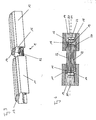
- connection system 1 To illustrate the connection of the connection system 1 according to the invention is in Fig. 4 a supervision of in Fig. 3 illustrated connection system shown.
- each band of light 11, 12 there is a current-carrying profile 13 and 14.
- the first contact-making device 15 is now visible here on the first current-carrying profile 13.
- the second contacting device 16 is mounted on the second current-carrying profile 14.
- some conductors 20 are shown as an example.
- the signals or the current which is applied to these conductors 20 is now available at the connection devices 17, 18 of the contacting devices 15, 16. In addition, the signal can be picked up and checked at the test socket 18.
- connection elements 22 can be connected in a simple manner to the respectively corresponding connection devices 17, 18.
- the asymmetrical design of the contacting device 15 and 16 to the central axis 21 of the current-carrying profiles 13, 14 is visible, for example, at the position of the PE connection devices 37.
- test sockets 19 are arranged such that they can be contacted at least on a contacting device in normal operation. It is also possible, for example, to connect a third light band 17, 18 via this test socket 19, if they are likewise designed as connection devices 17 and 18. Likewise, these connection devices 17, 18 can be used to connect the light bands 11, 12 with the building power supply.
- connection system according to the invention is characterized by a simple structure.
- a secure connection of two light bands or lights is possible by means of the system according to the invention.
Landscapes
- Arrangement Of Elements, Cooling, Sealing, Or The Like Of Lighting Devices (AREA)
- Details Of Connecting Devices For Male And Female Coupling (AREA)
Description
Die Erfindung betrifft ein Verbindungssystem für Lichtbänder oder Leuchten. Als Lichtband wird beispielsweise eine bandartige Aneinanderreihung von Einzelleuchten bezeichnet. Hierbei weist ein Lichtband z.B. eine Länge ab 3 m auf. Innerhalb eines Lichtbandes ist auch die Verkabelung für die Energieversorgung der Leuchtmittel der Leuchten vorgesehen. Eine durchgehende Verkabelung ermöglicht es, lediglich an einer Stelle das Lichtband mit Energie zu versorgen, indem die Verkabelung an die Gebäudeenergieversorgung angeschlossen wird. Werden mehrere Lichtbänder verwendet, so werden diese teilweise untereinander verbunden, so dass nur ein Lichtband an die Gebäudeenergieversorgung angeschlossen werden muss. Die Erfindung ist aber nicht nur auf Lichtbänder, sondern auch auf Leuchten anwendbar.The invention relates to a connection system for light bands or lights. As a light band, for example, a band-like juxtaposition of individual lights is called. Here, a light band comprises e.g. a length from 3 m up. Within a light strip, the wiring for the power supply of the lamps of the lights is provided. A continuous wiring makes it possible to supply the light band with energy only in one place by connecting the wiring to the building energy supply. If multiple light bands used, they are partially interconnected, so that only one light band must be connected to the building energy supply. However, the invention is not only applicable to light strips, but also to lights.
Herkömmlicherweise werden Lichtbänder derart miteinander verbunden, dass am Ende der Verkabelung eines Lichtbandes ein Stecker oder eine Buchse angebracht wird. Eine gleiche Einrichtung befindet sich am Ende der Verkabelung des zweiten Lichtbandes. Zwischen diesen beiden Lichtbändern wird ein speziell hierfür gefertigtes Verbindungselement angeschlossen, indem das Verbindungselement in den Stecker oder die Buchse der Verkabelung für die Energieversorgung des ersten Lichtbandes und in den Stecker oder die Buchse am zweiten Lichtband gesteckt wird. Hierdurch wird die Stromversorgung der beiden Lichtbänder miteinander verbunden und es ist möglich, lediglich eines der Lichtbänder an die Gebäudeenergieversorgung anzuschließen.Conventionally, light strips are connected to each other in such a way that at the end of the wiring of a light band, a plug or a socket is attached. A similar device is located at the end of the wiring of the second light band. Between these two light bands, a specially manufactured connecting element is connected by the connecting element is inserted into the plug or the socket of the wiring for the power supply of the first light strip and into the plug or socket on the second light strip. As a result, the power supply of the two light bands is connected together and it is possible to connect only one of the light bands to the building energy supply.
Dokument
Nachteitig an einer derartigen Konstruktion ist aber, dass sie zusätzliche Stecker oder Buchsen am Ende jedes Lichtbandes erfordert. Außerdem muss auch ein entsprechendes Verbindungselement gefertigt werden. Konstruktionsbedingt gibt es für die linke Seite des Lichtbandes einen anderen Stecker oder eine andere Buchse als für die rechte Seite. Dies erfordert zum einen beim Aufbau eines derartigen Lichtbandes erhöhte Präzision, damit die beiden Teile auf der richtigen Seite eingebaut werden. Zum anderen erhöht sich der Produktionsaufwand, da zwei verschiedene Teile produziert und auf Vorrat gehalten werden müssen. Auch beim Anschluss des Verbindungselementes an die beiden Lichtbänder muss eine erhöhte Vorsicht und Sorgfalt aufgewendet werden, um sicherzustellen, dass die einzelnen Leitungen des Lichtbandes nicht falsch angeschlossen sind, so dass beispielsweise auf dem Nullleiter eine Phase zu liegen kommt.Nachteitig of such a construction is that it requires additional plugs or sockets at the end of each light strip. In addition, a corresponding connecting element must be made. Due to the design, there is a different plug or socket for the left side of the light band than for the right one Page. This requires on the one hand in the construction of such a light band increased precision, so that the two parts are installed on the right side. On the other hand, the production costs increase because two different parts have to be produced and kept in stock. Even when connecting the connecting element to the two light bands, increased caution and care must be taken to ensure that the individual cables of the light band are not connected incorrectly, so that, for example, a phase comes to lie on the neutral conductor.
Des Weiteren ist es schwierig, eine korrekte Verbindung zweier Lichtbänder beziehungsweise deren Verkabelung zu überprüfen, da die einzelnen Leiter der Verkabelung aus Sicherheitsgründen nicht offen verlegt sind.Furthermore, it is difficult to check a correct connection of two light bands or their wiring, because the individual conductors of the wiring are not laid open for safety reasons.
Der Erfindung liegt die Aufgabe zugrunde, ein Verbindungssystem für Lichtbänder oder Leuchten zu schaffen, welches einfach aufgebaut ist und ein sicheres Verbinden zweier Lichtbänder oder Leuchten ermöglicht.The invention has for its object to provide a connection system for lighting strips or lights, which is simple and allows secure connection of two light bands or lights.
Die Aufgabe wird erfindungsgemäß durch ein Verbindungssystem mit den Merkmalen des Anspruchs 1 gelöst.The object is achieved by a connection system with the features of
Weitere vorteilhafte Ausführungsformen sind in den abhängigen Ansprüchen, der Beschreibung sowie den Figuren und der Beschreibung angegeben.Further advantageous embodiments are specified in the dependent claims, the description and the figures and the description.
Gemäß dem Anspruch 1 weist ein erfindungsgemäßes Verbindungssystem zum elektrischen Verbinden eines ersten Lichtbandes oder einer ersten Leuchte mit einem zweiten Lichtband oder einer zweiten Leuchte eine erste Kontaktierungseinrichtung auf. In den Lichtbändern oder Leuchten ist jeweils mindestens ein Stromführungsprofil mit mehreren in oder am Stromführungsprofil vorgesehenen Leitern angebracht. Die erste Kontaktierungseinrichtung dient zum elektrischen Kontaktieren der mehreren Leiter eines Stromführungsprofils.According to
Des Weiteren ist eine zweite Kontaktierungseinrichtung vorgesehen, welche im Wesentlichen identisch zu der ersten Kontaktierungseinrichtung aufgebaut ist. Hierbei sind an der ersten und an der zweiten Kontaktierungseinrichtung mehrere Anschlusseinrichtungen zum Anschluss mindestens eines Verbindungselementes vorgesehen. Jede Kontaktierungseinrichtung steht mit jeweils einem Leiter eines Stromführungsprofils in elektrisch leitendem Kontakt, wenn die Kontaktierungseinrichtung auf oder an einem Stromführungsprofil angebracht ist. Ferner ist mindestens ein Verbindungselement zum Aufbau einer elektrischen Verbindung zwischen mindestens einer Anschlusseinrichtung an der ersten Kontaktierungseinrichtung und mindestens einer korrespondierenden Anschlusseinrichtung an der zweiten Kontaktierungseinrichtung ausgebildet.Furthermore, a second contacting device is provided, which is constructed essentially identical to the first contacting device. Here, a plurality of connection devices for connecting at least one connecting element are provided on the first and on the second contacting device. Each contacting device is in electrically conductive contact with a respective conductor of a current-carrying profile when the contacting device is mounted on or on a current-carrying profile. Furthermore, at least one connecting element to the structure an electrical connection between at least one connection device on the first contacting device and at least one corresponding connection device on the second contacting device.
Ein Grundgedanke der Erfindung kann darin gesehen werden, ein neues vereinfachtes Verbindungssystem zu verwenden. In einem herkömmlichen System waren zwei unterschiedliche Stecker oder Buchsen an dem jeweiligen Ende der Verkabelung der Stromversorgung eines Lichtbandes notwendig. Diese mussten als linke und rechte Buchse oder Stecker ausgelegt werden. Zusätzlich waren entsprechende Verbindungsstecker notwendig, die auf die linke und rechte Buchse oder den Stecker angepasst waren. Durch die Erfindung, bei der nur noch zwei Kontaktierungseinrichtungen verwendet werden, welche im Wesentlichen gleich aufgebaut sind, werden weniger Bauteile zum Verbinden zweier Lichtbänder benötigt. Ein Vorteil ist darin zu sehen, dass zum Aufbau der Verbindung zwischen der Verkabelung für die Stromversorgung zweier Lichtbänder nun zweimal dasselbe Bauteil verwendet wird. Dies erleichtert die Lagerlogistik und die Produktion, da nur noch ein Bauteil hergestellt werden muss.A basic idea of the invention can be seen in using a new simplified connection system. In a conventional system, two different plugs or sockets were needed at the respective end of the cabling of the power supply of a light band. These had to be designed as left and right sockets or plugs. In addition, corresponding connectors were necessary, which were adapted to the left and right socket or the plug. The invention, in which only two contacting devices are used, which are constructed substantially the same, fewer components for connecting two light bands are needed. One advantage is the fact that twice the same component is used to establish the connection between the wiring for the power supply of two light bands. This facilitates warehouse logistics and production since only one component has to be produced.
Ein weiterer Aspekt der Erfindung kann darin gesehen werden, dass das Aufbauen einer elektrischen Verbindung zwischen den beiden Kontaktierungseinrichtungen vereinfacht wird. Dies wird dadurch erreicht, dass an jeder Kontaktierungseinrichtung mindestens eine Anschlusseinrichtung vorgesehen ist. Wenn die Kontaktierungseinrichtung an dem Stromführungsprofil angebracht ist, steht jede Anschlusseinrichtung mit einem Leiter des Stromführungsprofils in elektrisch leitendem Kontakt. Werden nun zwei, sich an derselben Stelle zweier unterschiedlicher Kontaktierungseinrichtungen befindliche Anschlusseinrichtungen elektrisch miteinander verbunden, wird relativ einfach sichergestellt, dass es zu keiner Falschkontaktierung kommt. Dies wird dadurch erreicht, dass die beiden Kontaktierungseinrichtungen sehr ähnlich, eventuell sogar gleich aufgebaut sind. Hierdurch befindet sich die Anschlusseinrichtung für einen bestimmten Leiter auf der ersten Kontaktierungseinrichtung genau an derselben Stelle, an der sich die Anschlusseinrichtung für denselben Leiter auf der zweiten Kontaktierungseinrichtung befindet.A further aspect of the invention can be seen in that the establishment of an electrical connection between the two contacting devices is simplified. This is achieved by providing at least one connection device on each contacting device. When the contacting device is attached to the current-carrying profile, each connection device is in electrically conductive contact with a conductor of the current-carrying profile. If two connection devices located at the same point on two different contacting devices are electrically connected to one another, it is relatively easy to ensure that no false contacting takes place. This is achieved in that the two contacting devices are very similar, possibly even the same. As a result, the connection device for a specific conductor on the first contacting device is located exactly at the same point at which the connection device for the same conductor is located on the second contacting device.
Unter Falschkontaktierung versteht man in diesem Zusammenhang, dass ein Leiter eines Stromführungsprofils eines ersten Lichtbandes mit einem anderen Leiter eines Stromführungsprofils eines zweiten Lichtbandes elektrisch verbunden wird, der nicht zum Leiten derselben Phase oder desselben Signals vorgesehen ist. Dies würde dazu führen, dass Leuchtmittel, die an dieses Stromführungsprofil mit dem falsch angeschlossenen Leiter angebracht werden, nicht korrekt funktionieren. In ungünstigen Fällen, bei einem Vertauschen der Phasen mit dem PE-Leiter, könnte sogar Spannung auf das Gehäuse des Lichtbandes gelangen. Durch den übersichtlichen Aufbau der jeweiligen Anschlusseinrichtung an derselben Stelle der beiden Kontaktierungseinrichtungen ist eine einfache Kontrolle des richtigen Anschlusses möglich.False contacting is understood in this context to mean that a conductor of a current-carrying profile of a first light band is electrically connected to another conductor of a current-carrying profile of a second light band which is not is provided for conducting the same phase or the same signal. This would result in bulbs attached to this power routing profile with the mismatched conductor not functioning properly. In unfavorable cases, when exchanging the phases with the PE conductor, even voltage could reach the housing of the light band. Due to the clear structure of the respective connection device at the same point of the two contacting devices a simple control of the correct connection is possible.
In einer bevorzugten Ausführungsform weist die Kontaktierungseinrichtung mindestens eine Anschlusseinrichtung pro Leiter des Stromführungsprofils auf. Hierdurch wird erreicht, dass jeder Leiter eines ersten Stromführungsprofils im ersten Lichtband mit dem entsprechenden Leiter eines zweiten Stromführungsprofils im zweiten Lichtband verbunden werden kann.In a preferred embodiment, the contacting device has at least one connection device per conductor of the current-carrying profile. This ensures that each conductor of a first current-carrying profile in the first light band can be connected to the corresponding conductor of a second current-carrying profile in the second light band.
Bevorzugt ist in diesem Zusammenhang, wenn die Kontaktierungseinrichtung als Einspeiser ausgeführt ist. Ein Einspeiser ist ein Bauteil, welches verwendet wird, um ein Stromführungsprofil an die Energieversorgung anzuschließen. Normalerweise wird ein Einspeiser auf oder an einem Stromführungsprofil vorgesehen. Der Einspeiser wird mit der Gebäudeverkabelung verbunden, um die Leiter auf dem Stromführungsprofil mit den Phasen, dem Nullleiter oder dem PE-Leiter zu verbinden. Ebenso werden hierbei die Leiter mit entsprechenden Steuerungsleitungen oder Notstromkreisen verbunden. Durch die Verwendung eines Einspeisers als Kontaktierungseinrichtung bietet sich der Vorteil, dass kein zusätzliches Bauteil produziert werden muss, sondern lediglich das Volumen der Einspeiserproduktion erhöht wird. Außerdem verringert sich dadurch der logistische Aufwand bei der Lagerhaltung.In this context, it is preferred if the contacting device is designed as a feeder. A feeder is a component that is used to connect a current carrying profile to the power supply. Normally, a feeder is provided on or at a current-carrying profile. The feeder is connected to the building wiring to connect the conductors on the current-carrying profile to the phases, the neutral or the PE conductor. Likewise, the conductors are connected to corresponding control lines or emergency circuits. By using a feeder as a contacting device has the advantage that no additional component must be produced, but only the volume of the feeder production is increased. In addition, this reduces the logistical effort in warehousing.
Um die Kontrolle zu vereinfachen, ob die Leiter jeweils richtig ohne eine Verpolung miteinander verbunden sind, hat es sich als vorteilhaft herausgestellt, an den Kontaktierungseinrichtungen zusätzlich mindestens eine Prüfbuchse pro Leiter des Stromführungsprofils vorzusehen. Über diese Prüfbuchse kann überprüft werden, welche Phasen oder Signale auf dem jeweiligen Leiter des Stromführungsprofils anliegen. Zusätzlich kann hiermit auch überprüft werden, ob die Verbindung mittels des erfindungsgemäßen Verbindungssystems richtig, d.h. leitend, ausgebildet ist. Ebenso können diese Prüfbuchsen verwendet werden, um die Fehlersuche zu vereinfachen, da sie entsprechende Messstellen bilden, an die ein Techniker bei der Überprüfung eines Lichtbandes leicht gelangen kann.In order to simplify the control as to whether the conductors are in each case correctly connected to one another without polarity reversal, it has proven advantageous to additionally provide at least one test socket per conductor of the current-carrying profile on the contacting devices. This test socket can be used to check which phases or signals are present on the respective conductor of the current-carrying profile. In addition, it is also possible to check whether the connection is correctly formed, ie conductive, by means of the connection system according to the invention. Likewise, these test sockets can be used to simplify troubleshooting because they are equivalent Form measuring points that a technician can easily access when checking a light band.
Grundsätzlich ist es möglich die Buchsen lediglich zum Anschluss von Prüfgeräten vorzusehen. In einer bevorzugten Ausführungsform sind die Prüfbuchsen allerdings als weitere Anschlusseinrichtung ausgeführt. Hierdurch wird es ermöglicht, dass die Kontaktierungseinrichtungen eine Doppelfunktion ausführen können. Zum einen können sie als Teil des Verbindungssystems verwendet werden, um zwei Stromführungsprofile zweier Lichtbänder miteinander leitend zu verbinden. Zum anderen können sie als Einspeiser verwendet werden, da die weiteren Anschlusseinrichtungen mit der Gebäudeverkabelung verbunden werden können.Basically, it is possible to provide the jacks only for connecting test equipment. In a preferred embodiment, however, the test sockets are designed as a further connection device. This makes it possible that the contacting devices can perform a dual function. On the one hand, they can be used as part of the connection system to conductively connect two current-carrying profiles of two light bands. On the other hand, they can be used as a feeder, since the other connection devices can be connected to the building wiring.
Hierdurch müssen weniger Bauteile an das Stromführungsprofil angebaut werden. Dies bietet den Vorteil, dass beim Anbringen von Leuchtmitteln, welche ebenfalls das Stromführungsprofil kontaktieren müssen, ein größerer Freiheitsgrad bei deren Positionierung zur Verfügung steht, da weniger auf bereits an dem Stromführungsprofil vorhandene Bauteile geachtet werden muss. Ein weiterer Vorteil ist, dass bei einer sternförmigen Anordnung von Lichtbändern von einer Kontaktierungseinrichtung zwei benachbarte Stromführungsprofile mit Signalen und Energie versorgt werden können.As a result, fewer components must be attached to the power supply profile. This offers the advantage that when attaching bulbs, which also have to contact the current-carrying profile, a greater degree of freedom in their positioning is available, since less attention must be paid to already existing on the current-carrying profile components. Another advantage is that with a star-shaped arrangement of light bands from a contacting device, two adjacent current-carrying profiles can be supplied with signals and energy.
In einer anderen Ausführung ist lediglich eine Anschlusseinrichtung an jeder Kontaktierungseinrichtung vorgesehen. Hierbei wird eine separate Kontaktierungseinrichtung für die Netzeinspeisung vorgesehen. Entsprechend ist jeweils eine Kontaktierungseinrichtung auf beiden Seiten der zwei zu verbindenden Stromführungsprofile zur elektrischen Verbindung dieser beiden Profile notwendig.In another embodiment, only one connection device is provided on each contacting device. Here, a separate contacting device is provided for the grid feed. Accordingly, in each case a contacting device is necessary on both sides of the two current-carrying profiles to be connected for the electrical connection of these two profiles.
Weiterhin ist es bevorzugt, wenn die Kontaktierungseinrichtungen einen Verpolschutz aufweisen. Dieser ist so ausgebildet, dass es schwer möglich ist, die Kontaktierungseinrichtung falsch auf das Stromführungsprofil aufzusetzen. Demnach kann eine Kontaktierungseinrichtung nur auf eine bestimmte Art und Weise, in einer bestimmten Ausrichtung an dem Stromführungsprofil angebracht werden. Ein derartiger Verpolschutz kann beispielsweise derart ausgeführt sein, dass die Kontaktierungseinrichtung asymmetrisch zur Mittelachse des Stromführungsprofils ausgebildet ist. Hierbei ist auch das Stromführungsprofil entsprechend asymmetrisch zu dessen Mittelachse ausgebildet. Dadurch kann die Kontaktierungseinrichtung nur in einer Art und Weise an dem Stromführungsprofil angebracht werden.Furthermore, it is preferred if the contacting devices have a polarity reversal protection. This is designed so that it is difficult to set up the contacting device incorrectly on the power supply profile. Accordingly, a contacting device can be attached to the current-carrying profile only in a specific manner, in a specific orientation. Such polarity reversal protection can for example be designed such that the contacting device is formed asymmetrically to the central axis of the current-carrying profile. Here, the current-carrying profile is designed according to asymmetrical to the central axis. As a result, the contacting device can be attached to the current-carrying profile only in one way.
Zur Erhöhung der Sicherheit sind die Kontaktierungseinrichtungen derart ausgebildet, dass sie beim Anbringen auf das Stromführungsprofil eine Zwangserdung des Lichtbandes oder der Leuchte bzw. der Gehäuse ausführen. Zusätzlich kann hierbei ein vorauseilender Kontakt zu einem Leiter vorgesehen sein. Dies ist insbesondere der PE-Leiter. Durch eine entsprechende Konstruktion wird erreicht, dass das Lichtband, an dem oder in dem das Stromführungsprofil vorgesehen ist, beim Einsetzen der Kontaktierungseinrichtung zuerst mit dem PE-Leiter verbunden wird. Bei etwaigen Fehlern ist der Monteur hierdurch geschützt und Kurzschlüsse oder falsche Verkabelung führen nicht dazu, dass am Gehäuse des Lichtbandes Spannung liegt.To increase the safety of the contacting devices are designed such that they perform a forced earthing of the light band or the lamp or the housing when mounted on the current-carrying profile. In addition, an anticipatory contact with a conductor can be provided in this case. This is especially the PE conductor. By a corresponding construction it is achieved that the light band, on which or in which the current-carrying profile is provided, is first connected to the PE conductor upon insertion of the contacting device. In the event of any faults, the installer is thus protected and short-circuits or incorrect wiring do not result in voltage being present at the housing of the light strip.
In einer bevorzugten Ausführungsform ist das mindestens eine Verbindungselement flexibel ausgebildet. Das Verbindungselement kann beispielsweise als Kupferdraht in Form eines einfachen Drahtleiters ausgeführt sein. Hierdurch wird bei der Montage zweier Lichtbänder ein gewisser Freiheitsgrad bei der Positionierung ermöglicht, da keine fest vorkonfektionierten Verbindungselemente vorgesehen sind. Somit können Lichtbänder beispielsweise in einer Kurve verlegt werden, bei der manche Verbindungselemente länger ausgeführt sein müssen, während andere kürzer sind.In a preferred embodiment, the at least one connecting element is flexible. The connecting element can be designed, for example, as a copper wire in the form of a simple wire conductor. As a result, a certain degree of freedom in the positioning is made possible during the installation of two light bands, since no fixed prefabricated connection elements are provided. Thus, light bands can be laid, for example, in a curve in which some fasteners must be made longer, while others are shorter.
Um die Handhabung der Verbindungselemente zu vereinfachen, ist es vorteilhaft, wenn diese als Flachbandkabel zusammengefasst sind. Hierdurch ergeben sich die Vorteile, dass die einzelnen Kabel übersichtlich zusammengefasst sind und dennoch weiterhin flexibel ausgebildet sind, so dass Lichtbänder auch in einer Kurve oder in einem Kreis verlegt werden können.In order to simplify the handling of the connecting elements, it is advantageous if they are combined as a ribbon cable. This results in the advantages that the individual cables are clearly summarized and still continue to be flexible, so that light bands can be laid in a curve or in a circle.
Die Erfindung wird nachfolgend anhand von Ausführungsbeispielen und schematischen Zeichnungen näher erläutert. In diesen Zeichnungen zeigen:
- Fig. 1
- eine perspektivische Ansicht einer Leuchte mit voneinander gelöster Tragschiene und Geräteträger als Element eines Lichtbandes;
- Fig. 2
- eine perspektivische Ansicht einer Kontaktierungseinrichtung des erfindungsgemäßen Verbindungssystems;
- Fig. 3
- eine perspektivische Ansicht eines an zwei Tragschienen angebauten erfindungsgemäßen Verbindungssystem; und
- Fig. 4
- eine Aufsicht auf ein an zwei Tragschienen angebautes erfindungsgemäßes Verbindungssystem.
- Fig. 1
- a perspective view of a lamp with separate support rail and equipment carrier as an element of a light strip;
- Fig. 2
- a perspective view of a contacting device of the connection system according to the invention;
- Fig. 3
- a perspective view of a mounted on two mounting rails inventive connection system; and
- Fig. 4
- a plan view of an attached to two mounting rails inventive connection system.
In
Die Tragschiene 3 ist als ein etwa U-förmiges Profil ausgebildet. In der Tragschiene 3 sind Aussparungen 9 vorgesehen, um Kabel für die Stromversorgung einzuführen. Des Weiteren ist in der Tragschiene 3 ein Stromführungsprofil 5 angebracht.The
Unterhalb der Tragschiene 3 ist ein Geräteträger 4 dargestellt. Dieser Geräteträger 4 weist an seiner der Tragschiene 3 zugewandten Seite einen Abnehmer 6 sowie beispielhaft ein oder mehrere elektronische Baugruppen 7 auf. Zur Montage dieser Leuchte 2 eines Lichtbandes wird der Geräteträger 4 von unten in die Tragschiene 3 eingeschoben und befestigt. Die Befestigung kann beispielsweise durch eine form- oder kraftschlüssige Klemmung mit entsprechenden Sicherungen durchgeführt werden.Below the
Beim Einsatz des Geräteträgers 4 in die Tragschiene 3 kontaktiert der Abnehmer 6 das Stromführungsprofil 5. Hierdurch ist es möglich, über den Abnehmer 6 Steuersignale und/oder Energie von dem Stromführungsprofil 5 abzunehmen.When using the
Am Geräteträger 4 sind zusätzlich noch zwei Anschlüsse 8 für Leuchtmittel vorgesehen. In der hier dargestellten Form kann beispielsweise eine Leuchtstoffröhre eingesetzt werden. Diese Leuchtstoffröhre wird mit über den Abnehmer 6 abgenommenem Strom versorgt. Im Bereich 7 können weitere elektronische und elektrische Einrichtungen vorgesehen sein, die zum Beispiel zum Betrieb des Leuchtmittels benötigt werden. Um mehrere derartige Leuchten oder Lichtbänder miteinander zu verbinden, wird das erfindungsgemäße Verbindungssystem 1 verwendet.On
Im Folgenden wird anhand der
In
Eine Anschlusseinrichtung 17 und die dazugehörige Prüfbuchse 19 sind jeweils nebeneinander angeordnet, so dass eine leichte Zuordnung möglich ist. Die Kombination aus Anschlusseinrichtung 17 und Prüfbuchse 19 für die unterschiedlichen Leiter ist an der Kontaktierungseinrichtung 15 versetzt angeordnet, so dass eine Zuordnung, welche Anschlusseinrichtung 17 für welchen Leiter vorgesehen ist, einfach möglich ist.A
In der hier dargestellten Ausführungsform befindet sich separiert von den normalen Anschlusseinrichtungen 17 und Prüfbuchsen 19 eine Anschlusseinrichtung 37 und eine Prüfbuchse 38 für den PE-Leiter. Hierdurch wird erreicht, dass die Anschlusseinrichtung 37 für den PE-Leiter beim Aufbau einer Verbindung mittels des erfindungsgemäßen Verbindungssystems 1 eindeutig erkennbar ist, und es speziell bei diesem für die Sicherheit relevanten Leiter nicht zu einer Verpolung oder falschen Verkabelung kommt.In the embodiment shown here is separated from the normal connection means 17 and
Des Weiteren ist an einer Seite der Kontaktierungseinrichtung 15 eine Klemmeinrichtung 26 vorgesehen. Diese Klemmeinrichtung 26 dient zur Befestigung der Kontaktierungseinrichtung 15 an dem Stromführungsprofil 5 und/oder der Tragschiene 3 des Lichtbandes.Furthermore, a
Neben den Anschlusseinrichtungen 17, 37 und den Prüfbuchsen 19, 39 ist zusätzlich auf beiden Seiten eine Leitungsfixierung 27 vorgesehen. An dieser Leitungsfixierung 27 können Kabelbinder befestigt werden, um Verbindungselemente 22 zwischen zwei Kontaktierungseinrichtungen 15 von auftretenden Kräften wie Zug zu entlasten.In addition to the
Die Tragschienen 5 des ersten 11 und des zweiten 12 Lichtbandes sind hierbei verkürzt dargestellt. Im Folgenden wird allgemein von Lichtband 11, 12 gesprochen, auch wenn in dem hier gezeigten Ausführungsbeispiel lediglich ein Teil davon, nämlich die Tragschiene 5 dargestellt ist.The support rails 5 of the first 11 and the second 12 light band are shown shortened here. The following is generally spoken of
In dem ersten Lichtband 11 ist ein Stromführungsprofil 13 eingebracht. Entsprechend ist in dem zweiten Lichtband 12 ein zweites Stromführungsprofil 14 angeordnet. Mittels des erfindungsgemäßen Verbindungssystems 1 werden diese beiden Stromführungsprofile 13, 14 miteinander elektrisch leitend verbunden. Hierzu ist auf dem ersten Stromführungsprofil 13 eine erste Kontaktierungseinrichtung 15 angebracht. Diese ist in
Zur Verdeutlichung des Anschlusses des erfindungsgemäßen Verbindungssystems 1 ist in
In jedem Lichtband 11, 12 befindet sich ein Stromführungsprofil 13 und 14. Auf dem ersten Stromführungsprofil 13 ist hier nun sichtbar die erste Kontaktierungseinrichtung 15 angebracht. Entsprechend ist auf dem zweiten Stromführungsprofil 14 die zweite Kontaktierungseinrichtung 16 angebracht. An den beiden Stromführungsprofilen 13, 14 sind exemplarisch einige Leiter 20 angedeutet dargestellt. Beim Anbringen einer Kontaktierungseinrichtung 15, 16 an ein Stromführungsprofil 13, 14 werden diese Leiter 20 jeweils kontaktiert. Die Signale oder der Strom, der an diesen Leitern 20 anliegt, steht nun an den Anschlusseinrichtungen 17, 18 der Kontaktierungseinrichtungen 15, 16 zur Verfügung. Zusätzlich kann an der Prüfbuchse 18 das Signal abgenommen und überprüft werden.In each band of light 11, 12 there is a current-carrying
Durch den im Wesentlichen gleichen Aufbau der beiden Kontaktierungseinrichtungen 15, 16 können die Verbindungselemente 22 in einfacher Weise an die jeweils korrespondierenden Anschlusseinrichtungen 17, 18 angeschlossen werden.Due to the substantially same structure of the two contacting
Die asymmetrische Ausbildung der Kontaktierungseinrichtung 15 und 16 zur Mittelachse 21 der Stromführungsprofile 13, 14 ist beispielsweise an der Position der PE-Anschlusseinrichtungen 37 sichtbar.The asymmetrical design of the contacting
Wie in Bezug auf die zweite Kontaktierungseinrichtung 16 gezeigt, liegen die Prüfbuchsen 19 derart angeordnet, dass sie zumindest auf einer Kontaktierungseinrichtung in normalem Betrieb kontaktierbar sind. Es ist beispielsweise auch möglich, über diese Prüfbuchse 19, wenn sie ebenfalls als Anschlusseinrichtungen 17 und 18 ausgebildet sind, ein drittes Lichtband 17, 18 anzuschließen. Ebenso können diese Anschlusseinrichtungen 17, 18 verwendet werden, um die Lichtbänder 11, 12 mit der Gebäudestromversorgung zu verbinden.As shown in relation to the second contacting
Das erfindungsgemäße Verbindungssystem zeichnet sich durch einen einfachen Aufbau aus. Außerdem ist mittels des erfindungsgemäßen Systems ein sicheres Verbinden zweier Lichtbänder oder Leuchten möglich.The connection system according to the invention is characterized by a simple structure. In addition, a secure connection of two light bands or lights is possible by means of the system according to the invention.
Claims (11)
- A connection system (1) for electrically connecting a first light strip (11) or a first lamp to a second light strip (12) or a second lamp,
wherein the light strips (11, 12) and/or the lamps have in each case at least one electricity guide profile (13, 14) with a plurality of conductors (20) provided in or on the electricity guide profile (13, 14),
with a first contacting apparatus (15) for electrically contacting the plurality of conductors (20) of an electricity guide profile (13, 14) and with a second contacting apparatus (16) which is essentially identically structured to the first contacting apparatus (15),
wherein, a plurality of attaching apparatuses (17, 18) for attaching at least one connecting element (22) are provided on the first (15) and on the second (16) contacting apparatus,
wherein, in the case of a contacting apparatus (15, 16) attached on or at the electricity guide profile (13, 14), each attaching apparatus (17, 18) is in electrically conductive contact with in each case one conductor (20) of the electricity guide profile (13, 14) and wherein the at least one connecting element (22) is constructed for setting up an electrically conductive connection between at least one attaching apparatus (17) on the first contacting apparatus (15) and at least one corresponding attaching apparatus (18) on the second contacting apparatus (16), characterised in that
at least one test socket (19), which is realised as a further attaching apparatus (17, 18), is constructed per conductor (20) of the electricity guide profile (13, 14) on the contacting apparatuses (15, 16). - The connection system according to Claim 1,
characterised
in that at least one attaching apparatus (17, 18) is constructed per conductor (20) of the electricity guide profile (13, 14) on the contacting apparatuses (15, 16). - The connection system according to Claim 1 or 2,
characterised
in that the contacting apparatuses (15, 16) are realised as suppliers of energy and/or signals to the electricity guide profile (13, 14). - The connection system according to one of Claims 1 to 3,
characterised
in that the contacting apparatuses (15, 16) have a reverse-polarity protection and are in particular constructed asymmetrically to the central axis (21) of the electricity guide profile (13, 14). - The connection system according to one of Claims 1 to 4,
characterised
in that the contacting apparatuses (15, 16) are designed for forced earthing of the light strip (11, 12) or the lamp. - The connection system according to one of Claims 1 to 5,
characterised
in that the contacting apparatuses (15, 16) are constructed for leading contact with a conductor (22), particularly the PE conductor, of the electricity guide profile (13, 14). - The connection system according to one of Claims 1 to 6,
characterised
in that the at least one connecting element (22) is flexibly constructed. - The connection system according to one of Claims 1 to 7,
characterised
in that a plurality of connecting elements (22) are combined in the form of a ribbon cable. - The connection system according to one of Claims 1 to 8,
characterised
in that a wire conductor is provided as connecting element (22). - The connection system according to one of Claims 1 to 9,
characterised
in that the respective further attaching apparatus (17, 18) is realised as a supplier. - Method for electrically connecting a first light strip (11) or a first lamp to a second light strip (12) or a second lamp, wherein the light strips (11, 12) and/or the lamps have in each case at least one electricity guide profile (13, 14) with a plurality of conductors (20) provided in or on the electricity guide profile (13, 14),
with a first contacting apparatus (15) for electrically contacting the plurality of conductors (20) of an electricity guide profile (13, 14) and with a second contacting apparatus (16) which is essentially identically structured to the first contacting apparatus (15),
wherein, a plurality of attaching apparatuses (17, 18) for attaching at least one connecting element (22) are provided on the first (15) and on the second (16) contacting apparatus,
wherein at least one test socket (19), which is realised as a further attaching apparatus (17, 18), is constructed per conductor (20) of the electricity guide profile (13, 14) on the contacting apparatuses (15, 16),
wherein, in the case of a contacting apparatus (15, 16) attached on or at the electricity guide profile (13, 14), each attaching apparatus (17, 18) is in electrically conductive contact with one conductor (20) of the electricity guide profile (13, 14) in each case,
in which the first contacting apparatus (15) is attached on or at the first light strip (11) or the first lamp,
in which the first contacting apparatus (16) is attached on or at the second light strip (12) or the second lamp, and
in which the at least one connecting element (22) is attached on at least one attaching apparatus (17) on the first contacting apparatus (15) and on a corresponding attaching apparatus (18) on the second contacting apparatus (16), in order to set up an electrically conductive connection.
Priority Applications (1)
| Application Number | Priority Date | Filing Date | Title |
|---|---|---|---|
| PL08008129T PL2091113T3 (en) | 2008-02-13 | 2008-04-28 | Connection system for light strips or lights |
Applications Claiming Priority (1)
| Application Number | Priority Date | Filing Date | Title |
|---|---|---|---|
| DE202008001964U DE202008001964U1 (en) | 2008-02-13 | 2008-02-13 | Connection system for lighting strips or luminaires |
Publications (2)
| Publication Number | Publication Date |
|---|---|
| EP2091113A1 EP2091113A1 (en) | 2009-08-19 |
| EP2091113B1 true EP2091113B1 (en) | 2011-10-19 |
Family
ID=39326884
Family Applications (1)
| Application Number | Title | Priority Date | Filing Date |
|---|---|---|---|
| EP08008129A Active EP2091113B1 (en) | 2008-02-13 | 2008-04-28 | Connection system for light strips or lights |
Country Status (3)
| Country | Link |
|---|---|
| EP (1) | EP2091113B1 (en) |
| DE (1) | DE202008001964U1 (en) |
| PL (1) | PL2091113T3 (en) |
Cited By (2)
| Publication number | Priority date | Publication date | Assignee | Title |
|---|---|---|---|---|
| CN105762591A (en) * | 2016-04-12 | 2016-07-13 | 国家电网公司 | Slidable power supply extension socket |
| DE202016104790U1 (en) | 2015-09-03 | 2016-12-06 | Wago Verwaltungsgesellschaft Mbh | Connectors |
Families Citing this family (5)
| Publication number | Priority date | Publication date | Assignee | Title |
|---|---|---|---|---|
| EP2264363B1 (en) * | 2009-06-16 | 2013-04-24 | RIDI-LEUCHTEN GmbH | Light, end cap and light ribbon |
| DE102010032383B4 (en) | 2010-07-27 | 2012-05-10 | Wago Verwaltungsgesellschaft Mbh | Busbar connector and busbar system with at least two adjacent busbars and a busbar connector |
| DE102010055789B4 (en) | 2010-12-23 | 2014-07-10 | Wago Verwaltungsgesellschaft Mbh | Busbar connector and busbar system with at least two adjacent busbars and a busbar connector |
| DE102016015767B4 (en) | 2016-07-29 | 2022-09-29 | Wago Verwaltungsgesellschaft Mbh | Protective cap and set of metal trough and protective cap |
| DE102017125279A1 (en) * | 2017-10-27 | 2019-05-02 | Wago Verwaltungsgesellschaft Mbh | Abgriffsteckverbinder |
Family Cites Families (5)
| Publication number | Priority date | Publication date | Assignee | Title |
|---|---|---|---|---|
| DE2743424A1 (en) * | 1977-09-27 | 1979-03-29 | Staff Kg | Connecting element for power supply bars - has cable sheath with ribs whose outline corresponds to that of coupling elements or bars |
| DE3710896A1 (en) * | 1987-04-01 | 1988-10-20 | Krone Ag | DISTRIBUTION BOARD FOR TELECOMMUNICATION CABLES, IN PARTICULAR HOUSE ENTRANCE DISTRIBUTION BOARD |
| DE4121639A1 (en) * | 1990-07-05 | 1992-01-16 | Dorma Glas Gmbh | Adaptor unit for power supply rail - has pins engaging with contact bushes to provide bridging action |
| US6358070B1 (en) * | 2001-06-05 | 2002-03-19 | Shan Chaing Lin | Track and connector arrangement for a track light |
| US20030021111A1 (en) * | 2001-07-30 | 2003-01-30 | Miller Jack V. | Multi-circuit tracklight system |
-
2008
- 2008-02-13 DE DE202008001964U patent/DE202008001964U1/en not_active Expired - Lifetime
- 2008-04-28 PL PL08008129T patent/PL2091113T3/en unknown
- 2008-04-28 EP EP08008129A patent/EP2091113B1/en active Active
Cited By (4)
| Publication number | Priority date | Publication date | Assignee | Title |
|---|---|---|---|---|
| DE202016104790U1 (en) | 2015-09-03 | 2016-12-06 | Wago Verwaltungsgesellschaft Mbh | Connectors |
| DE102015114741A1 (en) | 2015-09-03 | 2017-03-09 | Wago Verwaltungsgesellschaft Mbh | Connector and set of connector and connector part |
| DE102015114741B4 (en) | 2015-09-03 | 2018-08-30 | Wago Verwaltungsgesellschaft Mbh | Connector and set of connector and connector part |
| CN105762591A (en) * | 2016-04-12 | 2016-07-13 | 国家电网公司 | Slidable power supply extension socket |
Also Published As
| Publication number | Publication date |
|---|---|
| DE202008001964U1 (en) | 2008-04-24 |
| EP2091113A1 (en) | 2009-08-19 |
| PL2091113T3 (en) | 2012-03-30 |
Similar Documents
| Publication | Publication Date | Title |
|---|---|---|
| EP2091113B1 (en) | Connection system for light strips or lights | |
| EP2091111B1 (en) | Contact system for light strips or lights | |
| DE102017219230A1 (en) | Branching structure and wiring harness | |
| EP1992047B1 (en) | Arrangement for power distribution and contact-making therewith and protection of the outgoing lines | |
| DE102006032258A1 (en) | Electrical connector box for motor vehicles | |
| EP2580821B1 (en) | Electrical distribution device and method for fitting the same | |
| DE102007053535A1 (en) | Connection module and switching device with a connection module | |
| DE102010042158B4 (en) | Electrical distribution box | |
| DE4124487C2 (en) | adapter | |
| WO2007113030A1 (en) | Connection module for connecting a control unit or similar to a drive unit | |
| DE102010015449A1 (en) | Mounting arrangement for electrical appliances | |
| DE102012102842A1 (en) | Plug-in connection module mounted in recess of housing wall, has locking receptacle and/or locking unit which are configured so that secondary side of base plate rests against housing wall when clamping contact is inserted in housing | |
| DE20307863U1 (en) | Output voltage distributor with fuse | |
| DE2251020B2 (en) | CONNECTING DEVICE | |
| EP2694874B1 (en) | Device for fastening and contacting a lighting means and/or a lighting module, and lamp | |
| DE4017208C2 (en) | Three-phase generator, e.g. for vehicles | |
| DE102015110223B4 (en) | Assembly of a terminal device for connecting electrical conductors | |
| DE102007018175A1 (en) | Power splitter for current distribution within main power supply of motor vehicle, has fuses firmly connected with wiring harness and its cables in undetachable manner in form of crimping connection and directly connected with splitter bar | |
| DE69411294T2 (en) | Terminal block for electrical devices and power converters with such a terminal block | |
| EP1472766A1 (en) | Connecting or distributing device for electrical installation equipment | |
| AT516443A2 (en) | Luminaire with contacting module | |
| DE19700057C2 (en) | Data rail for the European installation bus (EIB) | |
| DE102004058712B4 (en) | Electric distribution box | |
| WO2018108498A1 (en) | Decoupling element for connecting power electronics to an electric machine | |
| DE102010028907A1 (en) | Connection contact arrangement for solar modules |
Legal Events
| Date | Code | Title | Description |
|---|---|---|---|
| PUAI | Public reference made under article 153(3) epc to a published international application that has entered the european phase |
Free format text: ORIGINAL CODE: 0009012 |
|
| AK | Designated contracting states |
Kind code of ref document: A1 Designated state(s): AT BE BG CH CY CZ DE DK EE ES FI FR GB GR HR HU IE IS IT LI LT LU LV MC MT NL NO PL PT RO SE SI SK TR |
|
| AX | Request for extension of the european patent |
Extension state: AL BA MK RS |
|
| 17P | Request for examination filed |
Effective date: 20100218 |
|
| AKX | Designation fees paid |
Designated state(s): DE FR GB PL |
|
| 17Q | First examination report despatched |
Effective date: 20100915 |
|
| GRAP | Despatch of communication of intention to grant a patent |
Free format text: ORIGINAL CODE: EPIDOSNIGR1 |
|
| GRAS | Grant fee paid |
Free format text: ORIGINAL CODE: EPIDOSNIGR3 |
|
| GRAA | (expected) grant |
Free format text: ORIGINAL CODE: 0009210 |
|
| AK | Designated contracting states |
Kind code of ref document: B1 Designated state(s): DE FR GB PL |
|
| REG | Reference to a national code |
Ref country code: GB Ref legal event code: FG4D Free format text: NOT ENGLISH |
|
| REG | Reference to a national code |
Ref country code: DE Ref legal event code: R096 Ref document number: 502008005211 Country of ref document: DE Effective date: 20111222 |
|
| REG | Reference to a national code |
Ref country code: PL Ref legal event code: T3 |
|
| PLBE | No opposition filed within time limit |
Free format text: ORIGINAL CODE: 0009261 |
|
| STAA | Information on the status of an ep patent application or granted ep patent |
Free format text: STATUS: NO OPPOSITION FILED WITHIN TIME LIMIT |
|
| 26N | No opposition filed |
Effective date: 20120720 |
|
| REG | Reference to a national code |
Ref country code: DE Ref legal event code: R097 Ref document number: 502008005211 Country of ref document: DE Effective date: 20120720 |
|
| REG | Reference to a national code |
Ref country code: FR Ref legal event code: PLFP Year of fee payment: 9 |
|
| REG | Reference to a national code |
Ref country code: FR Ref legal event code: PLFP Year of fee payment: 10 |
|
| REG | Reference to a national code |
Ref country code: FR Ref legal event code: PLFP Year of fee payment: 11 |
|
| PGFP | Annual fee paid to national office [announced via postgrant information from national office to epo] |
Ref country code: GB Payment date: 20240423 Year of fee payment: 17 |
|
| PGFP | Annual fee paid to national office [announced via postgrant information from national office to epo] |
Ref country code: DE Payment date: 20240429 Year of fee payment: 17 |
|
| PGFP | Annual fee paid to national office [announced via postgrant information from national office to epo] |
Ref country code: FR Payment date: 20240430 Year of fee payment: 17 |
|
| PGFP | Annual fee paid to national office [announced via postgrant information from national office to epo] |
Ref country code: PL Payment date: 20240404 Year of fee payment: 17 |