EP3094449B1 - Dispositif de fragmentation de milieu de projection - Google Patents
Dispositif de fragmentation de milieu de projection Download PDFInfo
- Publication number
- EP3094449B1 EP3094449B1 EP15737488.5A EP15737488A EP3094449B1 EP 3094449 B1 EP3094449 B1 EP 3094449B1 EP 15737488 A EP15737488 A EP 15737488A EP 3094449 B1 EP3094449 B1 EP 3094449B1
- Authority
- EP
- European Patent Office
- Prior art keywords
- subsonic
- blast media
- section
- fluid flow
- converging
- Prior art date
- Legal status (The legal status is an assumption and is not a legal conclusion. Google has not performed a legal analysis and makes no representation as to the accuracy of the status listed.)
- Active
Links
- 239000002245 particle Substances 0.000 claims description 49
- 239000012530 fluid Substances 0.000 claims description 25
- 238000000034 method Methods 0.000 claims description 19
- 238000011144 upstream manufacturing Methods 0.000 claims description 16
- 238000010276 construction Methods 0.000 claims description 3
- CURLTUGMZLYLDI-UHFFFAOYSA-N Carbon dioxide Chemical compound O=C=O CURLTUGMZLYLDI-UHFFFAOYSA-N 0.000 description 35
- 229910002092 carbon dioxide Inorganic materials 0.000 description 17
- 239000001569 carbon dioxide Substances 0.000 description 17
- XLYOFNOQVPJJNP-UHFFFAOYSA-N water Substances O XLYOFNOQVPJJNP-UHFFFAOYSA-N 0.000 description 9
- 230000008859 change Effects 0.000 description 3
- 230000001419 dependent effect Effects 0.000 description 3
- 230000003116 impacting effect Effects 0.000 description 3
- 239000004078 cryogenic material Substances 0.000 description 2
- 230000004048 modification Effects 0.000 description 2
- 238000012986 modification Methods 0.000 description 2
- 230000009467 reduction Effects 0.000 description 2
- 230000003068 static effect Effects 0.000 description 2
- 230000007704 transition Effects 0.000 description 2
- 238000005422 blasting Methods 0.000 description 1
- 235000011089 carbon dioxide Nutrition 0.000 description 1
- 230000000694 effects Effects 0.000 description 1
- 238000004513 sizing Methods 0.000 description 1
- 239000007787 solid Substances 0.000 description 1
- 238000003466 welding Methods 0.000 description 1
Images


Classifications
-
- B—PERFORMING OPERATIONS; TRANSPORTING
- B02—CRUSHING, PULVERISING, OR DISINTEGRATING; PREPARATORY TREATMENT OF GRAIN FOR MILLING
- B02C—CRUSHING, PULVERISING, OR DISINTEGRATING IN GENERAL; MILLING GRAIN
- B02C19/00—Other disintegrating devices or methods
- B02C19/0012—Devices for disintegrating materials by collision of these materials against a breaking surface or breaking body and/or by friction between the material particles (also for grain)
- B02C19/0043—Devices for disintegrating materials by collision of these materials against a breaking surface or breaking body and/or by friction between the material particles (also for grain) the materials to be pulverised being projected against a breaking surface or breaking body by a pressurised fluid
-
- B—PERFORMING OPERATIONS; TRANSPORTING
- B02—CRUSHING, PULVERISING, OR DISINTEGRATING; PREPARATORY TREATMENT OF GRAIN FOR MILLING
- B02C—CRUSHING, PULVERISING, OR DISINTEGRATING IN GENERAL; MILLING GRAIN
- B02C23/00—Auxiliary methods or auxiliary devices or accessories specially adapted for crushing or disintegrating not provided for in preceding groups or not specially adapted to apparatus covered by a single preceding group
- B02C23/08—Separating or sorting of material, associated with crushing or disintegrating
- B02C23/16—Separating or sorting of material, associated with crushing or disintegrating with separator defining termination of crushing or disintegrating zone, e.g. screen denying egress of oversize material
-
- B—PERFORMING OPERATIONS; TRANSPORTING
- B24—GRINDING; POLISHING
- B24C—ABRASIVE OR RELATED BLASTING WITH PARTICULATE MATERIAL
- B24C7/00—Equipment for feeding abrasive material; Controlling the flowability, constitution, or other physical characteristics of abrasive blasts
- B24C7/0046—Equipment for feeding abrasive material; Controlling the flowability, constitution, or other physical characteristics of abrasive blasts the abrasive material being fed in a gaseous carrier
Definitions
- the present invention relates to method and apparatus for reducing the size of blast media entrained in a subsonic fluid flow, and is particularly directed to a method and apparatus for reducing the size of carbon dioxide particles entrained in a subsonic gas flow.
- Carbon dioxide systems including apparatuses for creating solid carbon dioxide particles, for entraining particles in a transport gas and for directing entrained particles toward objects are well known, as are the various component parts associated therewith, such as nozzles, are shown in U.S. Patents 4,744,181 , 4,843,770 , 5,018,667 , 5,050,805 , 5,071,289 , 5,188,151 , 5,249,426 , 5,288,028 , 5,301,509 , 5,473,903 , 5,520,572 , 6,024,304 , 6,042,458 , 6,346,035 , 6,695,679 , 6,726,549 , 6,739,529 , 6,824,450 , 7,112,120 and 8,187,057 .
- Blast media fragmenters are well known apparatuses, configured to reduce the size of blast media, such as but not limited to carbon dioxide particles, entrained in a fluid flow, such as but not limited to air. Fragmenters define an internal flow path through which the entrained flow of blast media flows and include means for fragmenting the blast media disposed to be impacted by at least a portion of the flow of blast media.
- a (supersonic) blast media fragmenter comprising a body defining an internal flow path configured to maintain a fluid flow with entrained cryogenic blast media particle at (supersonic) speed throughout the length of the internal flow path, said internal flow path comprising an inlet, a converging section disposed downstream of said inlet, and an outlet disposed downstream of said converging section; as well as at least one fragmenting element disposed intermediate said converging section and said outlet.
- the document also discloses a method of changing a size of blast media particles entrained in a (supersonic) fluid flow, each of said blast media particles having a respective initial size, the method comprising propelling a plurality of said blast media particles through one or more openings defined by a fragmenting element and changing at least one of the propelled plurality of blast media particles from its respective initial size to a second smaller size by said propelling of said at least one of the plurality of said blast media particles through said one or more openings.
- the invention is defined by the fragmenter of independent claim 1 and the associated method of independent claim 8.
- a particle blast apparatus which includes cart 4, delivery hose 6, hand control 8, fragmenter 10 and blast nozzle 12.
- a blast media delivery assembly (not shown) which includes a hopper, a feeder disposed to receive particles from the hopper and to entrain particles into a flow of transport gas.
- Particle blast apparatus 2 is connectible to a source of transport fluid, delivered in the embodiment depicted by hose 14 which delivers a flow of air at a suitable pressure, such as 80 PSIG.
- Blast media such as carbon dioxide particles, indicated at 16, is deposited into the hopper through top 18 of the hopper.
- the carbon dioxide particles may be of any suitable size, such as a diameter of 3mm length of 3mm.
- the feeder entrains the particles into the transport gas, thereafter flowing at a subsonic speed through the internal flow passageway defined by delivery hose 6.
- Delivery hose 6 is depicted as a flexible hose, but any suitable structure may be used to convey the particles entrained in the transport gas.
- Hand control 8 allows the operator to control the operation of particle blast apparatus 2 and the flow of entrained particles. Downstream of control 8, the entrained particles flow into the internal flow path defined by fragmenter 10, and then into entrance 12a of blast nozzle 12. The particles flow from exit 12b of blast nozzle 12 and may be directed in the desired direction and/or at a desired target, such as a work piece (not shown).
- Blast nozzle 12 may be of any suitable configuration, for example, nozzle 12 may be a supersonic nozzle, a subsonic nozzle, or any other suitable structure configured to advance or deliver the blast media to the desired point of use.
- Control 8 may be omitted and the operation of the system controlled through controls on cart 4 or other suitable location.
- the blast nozzle 12 may be may mounted to a robotic arm and control of the nozzle orientation and flow accomplished through controls located remote to cart 4.
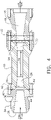
- fragmenter 10 includes body 20 which defines at least a portion of internal flow path 22 through which the entrained flow of blast media flows. Internal flow path 22 includes entrance 22a and exit 22b.
- Body 20 carries fragmenting element 24 which is disposed to be impacted by at least a portion of the flow of entrained blast media. In the embodiment depicted, fragmenting element 24 is disposed in internal flow path 22 such that the entirety of the flow flows through fragmenting element 24 resulting in all blast media larger than the openings (described below) of fragmenting element 24 impacting fragmenting element 24.
- internal flow path 22 includes converging section 26 which provides a reasonably smooth transition from the slower speed of the entrained flow upstream of fragmenter 10 to a notably higher velocity fluid flow, resulting in minimum loss of available compressed fluid energy.
- converging section 26 By converging to a smaller area, there is a corresponding change in fluid static pressure, which, for the subsonic flow, corresponds to the creation of a pressure pulse which is communicated through the fluid upstream and downstream of converging section 26.
- Constant cross-section area section 28 Downstream of converging section 26 is disposed constant cross-section area section 28 having a suitable length, L, to allow the Mach number of the entrained flow to remain sufficiently high enough for the media's kinetic energy to be sufficiently high enough, in view of diameter the cross-sectional area of section 28 and the area of the openings of fragmenting element 24, to ensure the media consistently impact and pass through fragmenting element 24 to avoid clogging. It is within the scope of teachings of this application to achieve the same results by configuring fragmenter 10 without constant cross-section area section 28, with converging section 26 having a convergence angle and length configured to produce equivalent results.
- expansion section 30 having a diverging or increasing cross-sectional area, of a relatively short length and low angle ⁇ which may optionally be included to account for water ice buildup along the wall of internal flow path 22 thereby reducing the potential for water ice clogging of fragmenting element 24.
- internal flow path 22 may include section 32 which presents a slight increase in cross-sectional area immediately downstream of fragmenting element 24, also reducing the potential for water ice clogging. Section 32 may be slightly converging as illustrated.
- body 20 is formed of two pieces, 20a and 20b secured to each other by fasteners with seal 20c therebetween. The two piece construction permits assembly of fragmenting element 24 therebetween in internal flow path 22.
- internal flow path 22 is depicted as circular, as can be seen in FIG. 3 , any suitable cross-sectional shape may be used, having the appropriately suitable cross-sectional areas as described herein.
- adapter 34 defines converging section 36 of internal flow path 22 which reduces the larger cross-section area of the entrained flow at inlet 38 to the cross-section area at entrance 40 of converging section 26, providing an even greater area reduction than depicted in converging section 26.
- Adaptor 34 is configured to mate complementarily with any component disposed immediately upstream thereof, such as control 8 in the embodiment depicted.
- the upstream component may be any suitable component, and by having different adaptor 34 configurations, a single fragmenter 10 configuration may be used with a range of upstream components.
- Adaptor 34 may be secured to body 20 in any suitable manner, such as by fasteners 42, and seal 44 may be included.
- adaptor 46 may, as illustrated, be connected to the exit end of fragmenter 10, configured to mate complementarily with any component disposed immediately downstream thereof.
- adaptor 46 includes diverging section 48.
- downstream components include a supersonic blast applicator or nozzle, a subsonic applicator/nozzle or any other component suitable for the intended use of the entrained particle flow.
- Fragmenting element 24 provides a plurality of passages 50, 52 also referred to herein as openings or cells, which are sized based on the desired final size of the media when the media exits the system.
- the openings of fragmenting element 24 may have any suitable shape, including rectangular, elongated, circular.
- FIG. 5 illustrates fragmenting element 24a configured as a wire mesh screen.
- support 54 may be provided as illustrated in FIG. 6 .
- Fragmenting element 24a may be attached to support 52 in any suitable manner, such as by welding at a plurality of locations about periphery 24b of fragmenting element 24a.
- FIG. 7 illustrates fragmenting element 24c with passages 52 laser cut or die cut. Fragmenting element 24c may therefore have sufficient thickness to need no additional support. Openings 52 may be undercut, have break edge or have a bell mouth shape.
- a plurality of fragmenting elements may be utilized, which may also be configured to have their relative angular orientations externally adjustable so as to provide a variable sized opening to provide variable control to the reduced size of the media.
- Fragmenting element 24 functions to change the blast media, such as the disclosed carbon dioxide particles, also referred to as dry ice particles, from a first size, which may be a generally uniform size for the media, to a second smaller size.
- a first size which may be a generally uniform size for the media
- a second smaller size all or a portion of the entrained media flows through the openings of fragmenting element 24, with each of the media colliding and/or passing through the openings, being reduced from their initial size to a second size, the second size being dependent upon the cell or opening size.
- a range of second sizes may be produced.
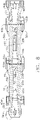
- FIG. 8 is a side cross-sectional view of two fragmenters 10a, 10b connected sequentially. Although two fragmenters are illustrated, more than two fragmenters may be sequentially arranged. Fragmenters 10a and 10b collectively define at least a portion of internal flow path 56 through which the entrained flow of blast media flows. Body 58a carries fragmenting element 60a which is disposed to be impacted by at least a portion of the flow of entrained blast media. In the embodiment depicted, fragmenting element 60a is disposed in internal flow path 56 such that the entirety of the flow flows through fragmenting element 60a resulting in all blast media larger than the openings of fragmenting element 60a impacting fragmenting element 60a.
- Body 58b carries fragmenting element 60b which is disposed to be impacted by at least a portion of the flow of entrained blast media.
- fragmenting element 60b is disposed in internal flow path 56 such that the entirety of the flow, which has previously passed through fragmenting element 60a, flows through fragmenting element 60b resulting in all blast media larger than the openings of fragmenting element 60b impacting fragmenting element 60b.
- internal flow path 56 includes converging section 26a which provides a reasonably smooth transition from the slower speed of the entrained flow upstream of fragmenter 10a to a notably higher velocity fluid flow, resulting in minimum loss of available compressed fluid energy.
- converging section 26a which provides a reasonably smooth transition from the slower speed of the entrained flow upstream of fragmenter 10a to a notably higher velocity fluid flow, resulting in minimum loss of available compressed fluid energy.
- Downstream of converging section 26a is disposed constant cross-section area section 28a having a suitable length, L a , to allow the Mach number of the entrained flow to remain sufficiently high enough for the media's kinetic energy to be sufficiently high enough, in view of diameter the cross-sectional area of section 28a and the area of the openings of fragmenting element 60a, to ensure the media consistently impact and pass through fragmenting element 60a to avoid clogging. It is within the scope of teachings of this application to achieve the same results by configuring fragmenter 10b without constant cross-section area section 28a, with converging section 26a having a convergence angle and length configured to produce equivalent results.
- expansion section 30a having a diverging or increasing cross-sectional area, of a relatively short length and low angle ⁇ a which may optionally be included to account for water ice buildup along the wall of internal flow path 56 thereby reducing the potential for water ice clogging of fragmenting element 60a.
- internal flow path 56 may include section 32a which presents a slight increase in cross-sectional area immediately downstream of fragmenting element 60a, also reducing the potential for water ice clogging. Section 32a may be slightly converging as illustrated.
- internal flow path 56 also includes converging section 26b and downstream converging section 26b having a constant cross-section area section 28b having a suitable length, L b , to allow the Mach number of the entrained flow to remain sufficiently high enough for the media's kinetic energy to be sufficiently high enough, in view of diameter the cross-sectional area of section 28b and the area of the openings of fragmenting element 60b, to ensure the media consistently impact and pass through fragmenting element 60b to avoid clogging. It is within the scope of teachings of this application to achieve the same results by configuring fragmenter 10b without constant cross-section area section 28b, with converging section 26b having a convergence angle and length configured to produce equivalent results.
- expansion section 30b downstream of constant cross-section area section 28b and upstream of fragmenting element 60b there is shown expansion section 30b, having a diverging or increasing cross-sectional area, of a relatively short length and low angle ⁇ b which may optionally be included to account for water ice buildup along the wall of internal flow path 56 thereby reducing the potential for water ice clogging of fragmenting element 60b.
- internal flow path 56 may include section 32b which presents a slight increase in cross-sectional area immediately downstream of fragmenting element 60b, also reducing the potential for water ice clogging. Section 32b may be slightly converging as illustrated.
- adapter 34a defines converging section 36a which reduces the larger cross-section area of the entrained flow at inlet 38a to the cross-section area at entrance 40a of converging section 26a, providing an even greater area reduction than depicted in converging section 26a.
- adaptor 46b may, as illustrated, be connected to the exit end of fragmenter 10b, configured to mate complementarily with any component disposed immediately downstream thereof.
- adaptor 46b includes diverging section 48b.
- downstream components include a supersonic blast applicator or nozzle, a subsonic applicator/nozzle or any other component suitable for the intended use of the entrained particle flow.
- Lengths L a and L b are suitable to together allow the Mach number of the entrained flow through flow path 56 to remain sufficiently high enough for the media's kinetic energy to be sufficiently high enough, in view of diameters D a and D b , the cross-sectional areas of sections 28a and 28b and the areas of the openings of fragmenting elements 60a and 60b, to ensure the media consistently impact and pass through fragmenting elements 60a and 60b to avoid clogging.
- corresponding sections of fragmenter 10a and 10b may have the same dimensions, e.g. , L a may equal L b , D a may equal D b .
- Fragmenting elements 60a and 60b may be the same or may be different.
- fragmenting element 60a may be sized to reduce the particle size to a first size, such as for example 3mm roughly in diameter
- fragmenting element 60b may be sized to reduce the particles to a second size, such as for example 2mm roughly in diameter.
- a first size such as for example 3mm roughly in diameter
- fragmenting element 60b may be sized to reduce the particles to a second size, such as for example 2mm roughly in diameter.
- gas will be released off, thereby compensating to some degree for the pressure drop across first fragmenting element 60a.
Landscapes
- Engineering & Computer Science (AREA)
- Food Science & Technology (AREA)
- Mechanical Engineering (AREA)
- Physical Or Chemical Processes And Apparatus (AREA)
- Cleaning In General (AREA)
- Disintegrating Or Milling (AREA)
- Physical Water Treatments (AREA)
- Drilling And Exploitation, And Mining Machines And Methods (AREA)
- Finish Polishing, Edge Sharpening, And Grinding By Specific Grinding Devices (AREA)
- Production Of Liquid Hydrocarbon Mixture For Refining Petroleum (AREA)
- Two-Way Televisions, Distribution Of Moving Picture Or The Like (AREA)
- Nozzles (AREA)
Claims (14)
- Dispositif de fragmentation (10 ; 10a, 10b) de milieux de projection subsoniques comprenanta. un corps (20 ; 58a, 58b) définissant un trajet d'écoulement interne (22 ; 56) configuré pour maintenir un écoulement de fluide avec des particules de milieux de projection cryogéniques entraînées à une vitesse subsonique sur toute la longueur du trajet d'écoulement interne, ledit trajet d'écoulement interne comprenant :i. une entrée (22a ; 38 ; 38a) ;ii. une section de convergence (26 ; 36) disposée en aval de ladite entrée ; etiii. une sortie (22b) disposée en aval de ladite section de convergence ; etb. au moins un élément de fragmentation (24 ; 60a, 60b) disposé entre ladite section de convergence et ladite sortie.
- Dispositif de fragmentation de milieux de projection subsoniques selon la revendication 1, dans lequel ledit corps est d'une construction unitaire.
- Dispositif de fragmentation de milieux de projection subsoniques selon l'une quelconque des revendications précédentes, dans lequel ladite section de convergence est disposée immédiatement en aval de ladite entrée.
- Dispositif de fragmentation de milieux de projection subsoniques selon l'une quelconque des revendications précédentes, comprenant une section à superficie en coupe transversale constante disposée entre ladite section de convergence et ledit au moins un élément de fragmentation.
- Dispositif de fragmentation de milieux de projection subsoniques selon la revendication 4, comprenant une section d'expansion disposée entre ladite section à superficie en coupe transversale constante et ledit au moins un élément de fragmentation.
- Dispositif de fragmentation de milieux de projection subsoniques selon l'une quelconque des revendications précédentes, dans lequel immédiatement en aval dudit au moins un élément de fragmentation ledit trajet d'écoulement interne a une superficie en coupe transversale plus grande qu'immédiatement en amont dudit au moins un élément de fragmentation.
- Dispositif de fragmentation de milieux de projection subsoniques selon l'une quelconque des revendications précédentes, comprenant une section d'expansion disposée entre ladite section de convergence et ledit au moins un élément de fragmentation.
- Méthode de modification d'une taille de particules de milieux de projection entraînées dans un écoulement de fluide subsonique, chacune desdites particules de milieux de projection ayant une taille initiale respective, la méthode comprenant :a. la convergence dudit écoulement de fluide subsonique (22 ; 56) depuis une première vitesse jusqu'à une seconde vitesse, ladite seconde vitesse étant subsonique et plus grande que ladite première vitesse ;b. la propulsion d'une pluralité desdites particules de milieux de projection à travers une ou plusieurs ouvertures (50 ; 52) définies par un élément de fragmentation (24 ; 60a, 60b) ; etc. la modification d'au moins une de la pluralité de particules de milieux de projection propulsée depuis sa taille initiale respective jusqu'à une seconde taille plus petite par ladite propulsion de ladite au moins une de la pluralité desdites particules de milieux de projection à travers lesdites une ou plusieurs ouvertures.
- Méthode selon la revendication 8, comprenant le maintien dudit écoulement de fluide subsonique à ladite seconde vitesse pour une première longueur avant de propulser ladite pluralité desdites particules de milieux de projection à travers lesdites une ou plusieurs ouvertures.
- Méthode selon l'une quelconque des revendications 8 et 9, comprenant, après que ledit écoulement de fluide subsonique a atteint ladite seconde vitesse, la non-convergence dudit écoulement de fluide subsonique pour une première longueur avant de propulser ladite pluralité desdites particules de milieux de projection à travers une ou plusieurs ouvertures.
- Méthode selon la revendication 10, dans laquelle la non-convergence dudit écoulement de fluide subsonique pour une première longueur comprend l'écoulement dudit écoulement de fluide subsonique à travers un passage interne, ledit passage interne ayant une superficie en coupe transversale constante le long de ladite première longueur.
- Méthode selon l'une quelconque des revendications 8 à 11, comprenant l'expansion de l'écoulement de fluide subsonique immédiatement avant de propulser ladite pluralité desdites particules de milieux de projection à travers une ou plusieurs ouvertures.
- Méthode selon l'une quelconque des revendications 8 à 12, comprenant l'expansion de l'écoulement de fluide subsonique immédiatement après avoir propulsé ladite pluralité desdites particules de milieux de projection à travers une ou plusieurs ouvertures.
- Méthode selon la revendication l'une quelconque des revendications 8 à 13, comprenant la convergence de l'écoulement de fluide subsonique après avoir propulsé ladite pluralité desdites particules de milieux de projection à travers une ou plusieurs ouvertures.
Applications Claiming Priority (2)
| Application Number | Priority Date | Filing Date | Title |
|---|---|---|---|
| US201461928398P | 2014-01-16 | 2014-01-16 | |
| PCT/US2015/011616 WO2015109101A1 (fr) | 2014-01-16 | 2015-01-15 | Dispositif de fragmentation de milieu de projection |
Publications (3)
| Publication Number | Publication Date |
|---|---|
| EP3094449A1 EP3094449A1 (fr) | 2016-11-23 |
| EP3094449A4 EP3094449A4 (fr) | 2017-09-13 |
| EP3094449B1 true EP3094449B1 (fr) | 2022-05-11 |
Family
ID=53520521
Family Applications (1)
| Application Number | Title | Priority Date | Filing Date |
|---|---|---|---|
| EP15737488.5A Active EP3094449B1 (fr) | 2014-01-16 | 2015-01-15 | Dispositif de fragmentation de milieu de projection |
Country Status (11)
| Country | Link |
|---|---|
| US (1) | US9931639B2 (fr) |
| EP (1) | EP3094449B1 (fr) |
| JP (1) | JP6618915B2 (fr) |
| CN (1) | CN105916632B (fr) |
| CA (1) | CA2934302C (fr) |
| DK (1) | DK3094449T3 (fr) |
| ES (1) | ES2921981T3 (fr) |
| MX (1) | MX2016009309A (fr) |
| PL (1) | PL3094449T3 (fr) |
| TW (1) | TWI677376B (fr) |
| WO (1) | WO2015109101A1 (fr) |
Families Citing this family (16)
| Publication number | Priority date | Publication date | Assignee | Title |
|---|---|---|---|---|
| US11383349B2 (en) * | 2014-08-20 | 2022-07-12 | Oceanit Laboratories, Inc. | Reduced noise abrasive blasting systems |
| JP6707555B2 (ja) | 2015-03-06 | 2020-06-10 | コールド・ジェット・エルエルシーCold Jet, LLC | 粒子フィーダー |
| AU2016341877B2 (en) | 2015-10-19 | 2019-12-19 | Cold Jet, Llc | Blast media comminutor |
| US20190321942A1 (en) | 2018-04-24 | 2019-10-24 | Cold Jet, Llc | Particle blast apparatus |
| DE102018120596A1 (de) * | 2018-08-23 | 2020-02-27 | Netzsch Trockenmahltechnik Gmbh | Verfahren und Vorrichtung zur Ausschleusung schwer mahlbarer Partikel aus einer Spiralstrahlmühle |
| CN109333595A (zh) * | 2018-10-31 | 2019-02-15 | 儒众智能科技(苏州)有限公司 | 一种可调节干冰颗粒大小的碎冰器 |
| WO2020123697A1 (fr) * | 2018-12-11 | 2020-06-18 | Oceanit Laboratories, Inc. | Systèmes de traitement au jet abrasif à bruit réduit |
| US20200282517A1 (en) * | 2018-12-11 | 2020-09-10 | Oceanit Laboratories, Inc. | Method and design for productive quiet abrasive blasting nozzles |
| DE102019108289A1 (de) * | 2019-03-29 | 2020-10-01 | acp systems AG | Vorrichtung zum Erzeugen eines CO2-Schnee-Strahls |
| USD993996S1 (en) | 2019-04-24 | 2023-08-01 | Cold Jet, Llc | Particle blast apparatus |
| CA3151023A1 (fr) | 2019-08-21 | 2021-02-25 | Cold Jet, Llc | Appareil de projection de particules |
| CA3159321A1 (fr) * | 2019-12-11 | 2021-06-17 | Christopher Sullivan | Procede et conception pour buses silencieuses productives d'abrasion par projection |
| EP4084930A1 (fr) | 2019-12-31 | 2022-11-09 | Cold Jet LLC | Procédé et appareil pour un flux de soufflage amélioré |
| WO2022236041A1 (fr) | 2021-05-07 | 2022-11-10 | Cold Jet, Llc | Méthode et appareil de formation de dioxyde de carbone solide |
| TW202348359A (zh) | 2022-02-21 | 2023-12-16 | 美商冷卻噴射公司 | 用於最小化噴砂噴嘴內及出口處之積冰的方法和設備 |
| WO2024006405A1 (fr) | 2022-07-01 | 2024-01-04 | Cold Jet, Llc | Procédé et appareil avec ventilation ou extraction de fluide de transport à partir d'un flux de soufflage |
Family Cites Families (77)
| Publication number | Priority date | Publication date | Assignee | Title |
|---|---|---|---|---|
| US1848122A (en) | 1930-02-20 | 1932-03-08 | Alois W Forster | Device for use in introducing alpha fluid into alpha conduit for flowing materials |
| US2282460A (en) | 1941-02-20 | 1942-05-12 | Elizabeth E Cummins | Dry-ice press |
| US3070967A (en) | 1959-09-03 | 1963-01-01 | Tesla L Uren | Dry ice manufacture |
| US3576112A (en) | 1968-11-29 | 1971-04-27 | Chemetron Corp | Filtering gas from pelletized co{hd 2 {l snow |
| US3670516A (en) | 1970-02-11 | 1972-06-20 | Air Reduction | Machine for making dry ice pellets |
| US3952530A (en) | 1974-08-20 | 1976-04-27 | Lewis Tyree Jr | CO2 -snow-making |
| US4038786A (en) | 1974-09-27 | 1977-08-02 | Lockheed Aircraft Corporation | Sandblasting with pellets of material capable of sublimation |
| US4253610A (en) | 1979-09-10 | 1981-03-03 | Larkin Joe M | Abrasive blast nozzle |
| JPS5654217A (en) | 1979-10-08 | 1981-05-14 | Daido Sanso Kk | Preparation of dry ice lump |
| EP0029867B1 (fr) | 1979-11-28 | 1982-12-01 | Iwatani Sangyo Kabushiki Kaisha | Dispositif pour la fabrication d'anhydride carbonique solide à partir d'anhydride carbonique liquide |
| US4655847A (en) | 1983-09-01 | 1987-04-07 | Tsuyoshi Ichinoseki | Cleaning method |
| DK550884A (da) | 1984-11-20 | 1986-05-21 | Knud Erik Westergaard | Fremgangsmaade og apparat til partikelblaesning med partikler af et materiale, der skifter tilstandsform |
| US4727687A (en) | 1984-12-14 | 1988-03-01 | Cryoblast, Inc. | Extrusion arrangement for a cryogenic cleaning apparatus |
| US4744181A (en) | 1986-11-17 | 1988-05-17 | Moore David E | Particle-blast cleaning apparatus and method |
| US4806171A (en) | 1987-04-22 | 1989-02-21 | The Boc Group, Inc. | Apparatus and method for removing minute particles from a substrate |
| US4817342A (en) | 1987-07-15 | 1989-04-04 | Whitemetal Inc. | Water/abrasive propulsion chamber |
| US4843770A (en) | 1987-08-17 | 1989-07-04 | Crane Newell D | Supersonic fan nozzle having a wide exit swath |
| US4843771A (en) | 1988-06-29 | 1989-07-04 | National Gypsum Company | Wall trim member |
| US5109636A (en) | 1988-08-01 | 1992-05-05 | Cold Jet, Inc. | Particle blast cleaning apparatus and method |
| US4947592A (en) | 1988-08-01 | 1990-08-14 | Cold Jet, Inc. | Particle blast cleaning apparatus |
| US5018667A (en) | 1989-02-08 | 1991-05-28 | Cold Jet, Inc. | Phase change injection nozzle |
| US5050805A (en) | 1989-02-08 | 1991-09-24 | Cold Jet, Inc. | Noise attenuating supersonic nozzle |
| CA1324591C (fr) | 1989-09-12 | 1993-11-23 | Somyong Visaisouk | Dispositif pour l'obtention, la classification et le dosage d'un materiau particulaire |
| US5071289A (en) | 1989-12-27 | 1991-12-10 | Alpheus Cleaning Technologies Corp. | Particulate delivery system |
| US5203794A (en) | 1991-06-14 | 1993-04-20 | Alpheus Cleaning Technologies Corp. | Ice blasting apparatus |
| USH1379H (en) | 1991-06-25 | 1994-12-06 | The United States Of America As Represented By The Secretary Of The Air Force | Supersonic fan nozzle for abrasive blasting media |
| US5188151A (en) | 1991-10-22 | 1993-02-23 | Cold Jet, Inc. | Flow diverter valve |
| US5571335A (en) | 1991-12-12 | 1996-11-05 | Cold Jet, Inc. | Method for removal of surface coatings |
| US5249426A (en) | 1992-06-02 | 1993-10-05 | Alpheus Cleaning Technologies Corp. | Apparatus for making and delivering sublimable pellets |
| US5301509A (en) | 1992-07-08 | 1994-04-12 | Cold Jet, Inc. | Method and apparatus for producing carbon dioxide pellets |
| WO1995027591A1 (fr) | 1992-07-08 | 1995-10-19 | Cold Jet, Inc. | Appareil et procede pour fabriquer des granules de neige carbonique |
| US5288028A (en) | 1992-09-10 | 1994-02-22 | Alpheus Cleaning Technologies Corp. | Apparatus for enhancing the feeding of particles from a hopper |
| US5283990A (en) | 1992-11-20 | 1994-02-08 | Church & Dwight Co., Inc. | Blast nozzle with inlet flow straightener |
| US5265383A (en) | 1992-11-20 | 1993-11-30 | Church & Dwight Co., Inc. | Fan nozzle |
| TW218852B (en) | 1992-12-23 | 1994-01-11 | D Fraresso William | Apparatus for real time ice supply to ice blasting system |
| CA2113291A1 (fr) | 1993-01-26 | 1994-07-27 | William D. Fraresso | Appareil d'alimentation en glace en temps reel pour systeme de grenaillage a glace |
| US5545073A (en) | 1993-04-05 | 1996-08-13 | Ford Motor Company | Silicon micromachined CO2 cleaning nozzle and method |
| US5525093A (en) | 1993-04-27 | 1996-06-11 | Westinghouse Electric Corporation | Cleaning method and apparatus |
| JP2772464B2 (ja) | 1993-10-22 | 1998-07-02 | 昭和炭酸株式会社 | 粉粒体の供給装置 |
| US5528907A (en) | 1994-04-11 | 1996-06-25 | Pint; Kenneth R. | Method and apparatus for automatically producing a small block of solid carbon dioxide |
| US5509849A (en) | 1994-04-18 | 1996-04-23 | Church & Dwight Co., Inc. | Blast nozzle for water injection and method of using same for blast cleaning solid surfaces |
| US5520572A (en) | 1994-07-01 | 1996-05-28 | Alpheus Cleaning Technologies Corp. | Apparatus for producing and blasting sublimable granules on demand |
| US5765766A (en) | 1994-12-08 | 1998-06-16 | Minolta Co., Ltd. | Nozzle for jet mill |
| US6173916B1 (en) | 1994-12-15 | 2001-01-16 | Eco-Snow Systems, Inc. | CO2jet spray nozzles with multiple orifices |
| US5660580A (en) | 1995-02-28 | 1997-08-26 | Cold Jet, Inc. | Nozzle for cryogenic particle blast system |
| US5679062A (en) | 1995-05-05 | 1997-10-21 | Ford Motor Company | CO2 cleaning nozzle and method with enhanced mixing zones |
| US5623831A (en) | 1995-05-10 | 1997-04-29 | Mesher; Terry | Fluidized particle production system and process |
| US5616067A (en) | 1996-01-16 | 1997-04-01 | Ford Motor Company | CO2 nozzle and method for cleaning pressure-sensitive surfaces |
| US6042458A (en) | 1996-05-31 | 2000-03-28 | Cold Jet, Inc. | Turn base for entrained particle flow |
| US5795214A (en) | 1997-03-07 | 1998-08-18 | Cold Jet, Inc. | Thrust balanced turn base for the nozzle assembly of an abrasive media blasting system |
| AU747679B2 (en) | 1997-07-11 | 2002-05-16 | Waterjet Technology, Inc. | Method and apparatus for producing a high-velocity particle stream |
| US6346035B1 (en) | 1998-12-24 | 2002-02-12 | Cae Alpheus, Inc. | Generation of an airstream with subliminable solid particles |
| US6739529B2 (en) | 1999-08-06 | 2004-05-25 | Cold Jet, Inc. | Non-metallic particle blasting nozzle with static field dissipation |
| US6318649B1 (en) | 1999-10-06 | 2001-11-20 | Cornerstone Technologies, Llc | Method of creating ultra-fine particles of materials using a high-pressure mill |
| US6431470B2 (en) | 2000-02-25 | 2002-08-13 | The Boeing Company | Low-noise air nozzle |
| US6726549B2 (en) | 2000-09-08 | 2004-04-27 | Cold Jet, Inc. | Particle blast apparatus |
| US7112120B2 (en) | 2002-04-17 | 2006-09-26 | Cold Jet Llc | Feeder assembly for particle blast system |
| GB2372718B (en) | 2001-01-04 | 2004-07-14 | Workinter Ltd | Nozzle intended for the concentrated distribution of a fluid for scouring of surfaces |
| US6579041B2 (en) | 2001-02-20 | 2003-06-17 | George Hobbs | Pre-screening element for pneumatic particle transport systems |
| US20030064665A1 (en) | 2001-09-28 | 2003-04-03 | Opel Alan E. | Apparatus to provide dry ice in different particle sizes to an airstream for cleaning of surfaces |
| US6695685B2 (en) | 2001-10-12 | 2004-02-24 | Cae Alpheus, Inc. | Low flow rate nozzle system for dry ice blasting |
| US6447377B1 (en) | 2001-10-12 | 2002-09-10 | Cae Alpheus, Inc. | Dry ice blasting gun with adjustable handle |
| US6695679B2 (en) | 2001-10-15 | 2004-02-24 | Cae Alpheus, Inc. | Enablement of selection of gas/dry ice ratios within an allowable range, and dynamic maintenance of the ratio in a blasting stream |
| DE10224778A1 (de) | 2002-06-04 | 2003-12-18 | Linde Ag | Trockeneisstrahlanlage |
| ATE322357T1 (de) | 2002-09-20 | 2006-04-15 | Jens-Werner Kipp | Strahlverfahren und -vorrichtung |
| CA2519214A1 (fr) | 2003-03-14 | 2004-09-23 | Workinter Limited | Procede pour le prelevement selectif des materiaux presents dans une ou plusieurs couches sur un objet et dispositif pour mettre en oeuvre ce procede |
| JP4290530B2 (ja) * | 2003-11-11 | 2009-07-08 | 株式会社不二製作所 | 噴射ノズル、及び該噴射ノズルを備えたブラスト加工装置、並びにブラスト加工方法、該ブラスト加工方法による潤滑層の形成方法 |
| TWI281115B (en) | 2005-01-25 | 2007-05-11 | Promos Technologies Inc | Integration system for managing photolithography tools and the method for operating the same |
| DE102005005638B3 (de) | 2005-02-05 | 2006-02-09 | Cryosnow Gmbh | Verfahren und Vorrichtung zum Reinigen, Aktivieren oder Vorbehandeln von Werkstücken mittels Kohlendioxidschnee-Strahlen |
| DE102007014284B4 (de) | 2007-03-19 | 2009-02-26 | Alfred Kärcher Gmbh & Co. Kg | Vorrichtung zum Zerkleinern von Trockeneisgranulat und Trockeneisabgabeanordnung mit einer derartigen Vorrichtung |
| DE102007018338B4 (de) | 2007-04-13 | 2010-09-23 | Technische Universität Berlin | Vorrichtung und Verfahren zum Partikelstrahlen mittels gefrorener Gaspartikel |
| US8257147B2 (en) | 2008-03-10 | 2012-09-04 | Regency Technologies, Llc | Method and apparatus for jet-assisted drilling or cutting |
| JP2010137341A (ja) * | 2008-12-12 | 2010-06-24 | Nikon Corp | 噴射加工装置 |
| US8187057B2 (en) | 2009-01-05 | 2012-05-29 | Cold Jet Llc | Blast nozzle with blast media fragmenter |
| US8454409B2 (en) * | 2009-09-10 | 2013-06-04 | Rave N.P., Inc. | CO2 nozzles |
| CN103261094B (zh) | 2010-10-19 | 2016-08-10 | 冷喷有限责任公司 | 用于将二氧化碳颗粒成型为块体的方法和设备 |
| WO2014066589A1 (fr) | 2012-10-24 | 2014-05-01 | Cold Jet, Llc | Appareil comprenant au moins un impulseur ou déflecteur et destiné à distribuer des particules de dioxyde de carbone et procédé d'utilisation |
-
2015
- 2015-01-14 US US14/596,607 patent/US9931639B2/en active Active
- 2015-01-15 MX MX2016009309A patent/MX2016009309A/es active IP Right Grant
- 2015-01-15 JP JP2016547073A patent/JP6618915B2/ja active Active
- 2015-01-15 PL PL15737488.5T patent/PL3094449T3/pl unknown
- 2015-01-15 CA CA2934302A patent/CA2934302C/fr active Active
- 2015-01-15 ES ES15737488T patent/ES2921981T3/es active Active
- 2015-01-15 CN CN201580004646.XA patent/CN105916632B/zh active Active
- 2015-01-15 EP EP15737488.5A patent/EP3094449B1/fr active Active
- 2015-01-15 WO PCT/US2015/011616 patent/WO2015109101A1/fr active Application Filing
- 2015-01-15 DK DK15737488.5T patent/DK3094449T3/da active
- 2015-01-16 TW TW104101584A patent/TWI677376B/zh active
Also Published As
| Publication number | Publication date |
|---|---|
| CA2934302A1 (fr) | 2015-07-23 |
| EP3094449A1 (fr) | 2016-11-23 |
| DK3094449T3 (da) | 2022-07-04 |
| ES2921981T3 (es) | 2022-09-05 |
| US9931639B2 (en) | 2018-04-03 |
| WO2015109101A1 (fr) | 2015-07-23 |
| CN105916632A (zh) | 2016-08-31 |
| JP6618915B2 (ja) | 2019-12-11 |
| TW201544192A (zh) | 2015-12-01 |
| CN105916632B (zh) | 2018-09-28 |
| PL3094449T3 (pl) | 2022-08-08 |
| CA2934302C (fr) | 2019-10-22 |
| JP2017505710A (ja) | 2017-02-23 |
| MX2016009309A (es) | 2016-10-07 |
| TWI677376B (zh) | 2019-11-21 |
| EP3094449A4 (fr) | 2017-09-13 |
| US20150196921A1 (en) | 2015-07-16 |
Similar Documents
| Publication | Publication Date | Title |
|---|---|---|
| EP3094449B1 (fr) | Dispositif de fragmentation de milieu de projection | |
| JP4989859B2 (ja) | コールドスプレー用ノズルならびにこれを利用したコールドスプレー装置及び方法 | |
| EP2529843B1 (fr) | Buse à flux inverse de génération de jets cavitants ou pulsés | |
| CN106525627B (zh) | 一种超音速喷砂枪 | |
| US8006961B1 (en) | Apparatus and method for treating process fluid | |
| EP2110178A1 (fr) | Buse de pulvérisation dynamique de gaz froid | |
| EP3197605B1 (fr) | Vanne d'éjection de poussières et de gaz | |
| AU2014408517A1 (en) | Pneumatic atomizing nozzle | |
| US20230381924A1 (en) | Method and apparatus for enhanced blast stream | |
| EP2835221B1 (fr) | Dispositif de traitement de mine et procédé de traitement de mine | |
| CN103939127B (zh) | 配备多重喇叭形扩散器的引射式除尘器 | |
| JP2010137341A (ja) | 噴射加工装置 | |
| US20180222016A1 (en) | Wet blasting machines | |
| US5501398A (en) | Device for liquid and solid delivery from crop spraying aircraft | |
| RU2800349C1 (ru) | Способ и устройство для усовершенствования потока для струйной обработки | |
| WO2012166058A1 (fr) | Tuyère d'éjecteur à effet coanda présentant une entrée de fluide secondaire | |
| US20020146967A1 (en) | Method and apparatus for ice blasting | |
| CN115814975A (zh) | 一种冷喷涂枪 | |
| CA2911123C (fr) | Dispositifs et procedes de regulation de jet | |
| TW202348359A (zh) | 用於最小化噴砂噴嘴內及出口處之積冰的方法和設備 | |
| MXPA00000434A (en) | Method and apparatus for producing a high-velocity particle stream |
Legal Events
| Date | Code | Title | Description |
|---|---|---|---|
| PUAI | Public reference made under article 153(3) epc to a published international application that has entered the european phase |
Free format text: ORIGINAL CODE: 0009012 |
|
| 17P | Request for examination filed |
Effective date: 20160726 |
|
| AK | Designated contracting states |
Kind code of ref document: A1 Designated state(s): AL AT BE BG CH CY CZ DE DK EE ES FI FR GB GR HR HU IE IS IT LI LT LU LV MC MK MT NL NO PL PT RO RS SE SI SK SM TR |
|
| AX | Request for extension of the european patent |
Extension state: BA ME |
|
| DAX | Request for extension of the european patent (deleted) | ||
| A4 | Supplementary search report drawn up and despatched |
Effective date: 20170814 |
|
| RIC1 | Information provided on ipc code assigned before grant |
Ipc: B24C 5/02 20060101AFI20170808BHEP Ipc: B24C 5/04 20060101ALI20170808BHEP |
|
| STAA | Information on the status of an ep patent application or granted ep patent |
Free format text: STATUS: EXAMINATION IS IN PROGRESS |
|
| 17Q | First examination report despatched |
Effective date: 20191008 |
|
| STAA | Information on the status of an ep patent application or granted ep patent |
Free format text: STATUS: EXAMINATION IS IN PROGRESS |
|
| GRAP | Despatch of communication of intention to grant a patent |
Free format text: ORIGINAL CODE: EPIDOSNIGR1 |
|
| STAA | Information on the status of an ep patent application or granted ep patent |
Free format text: STATUS: GRANT OF PATENT IS INTENDED |
|
| INTG | Intention to grant announced |
Effective date: 20210922 |
|
| GRAJ | Information related to disapproval of communication of intention to grant by the applicant or resumption of examination proceedings by the epo deleted |
Free format text: ORIGINAL CODE: EPIDOSDIGR1 |
|
| STAA | Information on the status of an ep patent application or granted ep patent |
Free format text: STATUS: EXAMINATION IS IN PROGRESS |
|
| INTC | Intention to grant announced (deleted) | ||
| GRAS | Grant fee paid |
Free format text: ORIGINAL CODE: EPIDOSNIGR3 |
|
| STAA | Information on the status of an ep patent application or granted ep patent |
Free format text: STATUS: GRANT OF PATENT IS INTENDED |
|
| GRAP | Despatch of communication of intention to grant a patent |
Free format text: ORIGINAL CODE: EPIDOSNIGR1 |
|
| GRAA | (expected) grant |
Free format text: ORIGINAL CODE: 0009210 |
|
| STAA | Information on the status of an ep patent application or granted ep patent |
Free format text: STATUS: THE PATENT HAS BEEN GRANTED |
|
| INTG | Intention to grant announced |
Effective date: 20220329 |
|
| AK | Designated contracting states |
Kind code of ref document: B1 Designated state(s): AL AT BE BG CH CY CZ DE DK EE ES FI FR GB GR HR HU IE IS IT LI LT LU LV MC MK MT NL NO PL PT RO RS SE SI SK SM TR |
|
| REG | Reference to a national code |
Ref country code: GB Ref legal event code: FG4D |
|
| REG | Reference to a national code |
Ref country code: CH Ref legal event code: EP |
|
| REG | Reference to a national code |
Ref country code: AT Ref legal event code: REF Ref document number: 1490986 Country of ref document: AT Kind code of ref document: T Effective date: 20220515 |
|
| REG | Reference to a national code |
Ref country code: DE Ref legal event code: R096 Ref document number: 602015078890 Country of ref document: DE |
|
| REG | Reference to a national code |
Ref country code: IE Ref legal event code: FG4D |
|
| REG | Reference to a national code |
Ref country code: DK Ref legal event code: T3 Effective date: 20220627 |
|
| REG | Reference to a national code |
Ref country code: ES Ref legal event code: FG2A Ref document number: 2921981 Country of ref document: ES Kind code of ref document: T3 Effective date: 20220905 |
|
| REG | Reference to a national code |
Ref country code: LT Ref legal event code: MG9D |
|
| REG | Reference to a national code |
Ref country code: NL Ref legal event code: MP Effective date: 20220511 |
|
| REG | Reference to a national code |
Ref country code: SK Ref legal event code: T3 Ref document number: E 40110 Country of ref document: SK |
|
| REG | Reference to a national code |
Ref country code: AT Ref legal event code: MK05 Ref document number: 1490986 Country of ref document: AT Kind code of ref document: T Effective date: 20220511 |
|
| PG25 | Lapsed in a contracting state [announced via postgrant information from national office to epo] |
Ref country code: SE Free format text: LAPSE BECAUSE OF FAILURE TO SUBMIT A TRANSLATION OF THE DESCRIPTION OR TO PAY THE FEE WITHIN THE PRESCRIBED TIME-LIMIT Effective date: 20220511 Ref country code: PT Free format text: LAPSE BECAUSE OF FAILURE TO SUBMIT A TRANSLATION OF THE DESCRIPTION OR TO PAY THE FEE WITHIN THE PRESCRIBED TIME-LIMIT Effective date: 20220912 Ref country code: NO Free format text: LAPSE BECAUSE OF FAILURE TO SUBMIT A TRANSLATION OF THE DESCRIPTION OR TO PAY THE FEE WITHIN THE PRESCRIBED TIME-LIMIT Effective date: 20220811 Ref country code: NL Free format text: LAPSE BECAUSE OF FAILURE TO SUBMIT A TRANSLATION OF THE DESCRIPTION OR TO PAY THE FEE WITHIN THE PRESCRIBED TIME-LIMIT Effective date: 20220511 Ref country code: LT Free format text: LAPSE BECAUSE OF FAILURE TO SUBMIT A TRANSLATION OF THE DESCRIPTION OR TO PAY THE FEE WITHIN THE PRESCRIBED TIME-LIMIT Effective date: 20220511 Ref country code: HR Free format text: LAPSE BECAUSE OF FAILURE TO SUBMIT A TRANSLATION OF THE DESCRIPTION OR TO PAY THE FEE WITHIN THE PRESCRIBED TIME-LIMIT Effective date: 20220511 Ref country code: GR Free format text: LAPSE BECAUSE OF FAILURE TO SUBMIT A TRANSLATION OF THE DESCRIPTION OR TO PAY THE FEE WITHIN THE PRESCRIBED TIME-LIMIT Effective date: 20220812 Ref country code: FI Free format text: LAPSE BECAUSE OF FAILURE TO SUBMIT A TRANSLATION OF THE DESCRIPTION OR TO PAY THE FEE WITHIN THE PRESCRIBED TIME-LIMIT Effective date: 20220511 Ref country code: BG Free format text: LAPSE BECAUSE OF FAILURE TO SUBMIT A TRANSLATION OF THE DESCRIPTION OR TO PAY THE FEE WITHIN THE PRESCRIBED TIME-LIMIT Effective date: 20220811 Ref country code: AT Free format text: LAPSE BECAUSE OF FAILURE TO SUBMIT A TRANSLATION OF THE DESCRIPTION OR TO PAY THE FEE WITHIN THE PRESCRIBED TIME-LIMIT Effective date: 20220511 |
|
| PG25 | Lapsed in a contracting state [announced via postgrant information from national office to epo] |
Ref country code: RS Free format text: LAPSE BECAUSE OF FAILURE TO SUBMIT A TRANSLATION OF THE DESCRIPTION OR TO PAY THE FEE WITHIN THE PRESCRIBED TIME-LIMIT Effective date: 20220511 Ref country code: LV Free format text: LAPSE BECAUSE OF FAILURE TO SUBMIT A TRANSLATION OF THE DESCRIPTION OR TO PAY THE FEE WITHIN THE PRESCRIBED TIME-LIMIT Effective date: 20220511 Ref country code: IS Free format text: LAPSE BECAUSE OF FAILURE TO SUBMIT A TRANSLATION OF THE DESCRIPTION OR TO PAY THE FEE WITHIN THE PRESCRIBED TIME-LIMIT Effective date: 20220911 |
|
| PG25 | Lapsed in a contracting state [announced via postgrant information from national office to epo] |
Ref country code: SM Free format text: LAPSE BECAUSE OF FAILURE TO SUBMIT A TRANSLATION OF THE DESCRIPTION OR TO PAY THE FEE WITHIN THE PRESCRIBED TIME-LIMIT Effective date: 20220511 Ref country code: RO Free format text: LAPSE BECAUSE OF FAILURE TO SUBMIT A TRANSLATION OF THE DESCRIPTION OR TO PAY THE FEE WITHIN THE PRESCRIBED TIME-LIMIT Effective date: 20220511 Ref country code: EE Free format text: LAPSE BECAUSE OF FAILURE TO SUBMIT A TRANSLATION OF THE DESCRIPTION OR TO PAY THE FEE WITHIN THE PRESCRIBED TIME-LIMIT Effective date: 20220511 |
|
| REG | Reference to a national code |
Ref country code: DE Ref legal event code: R097 Ref document number: 602015078890 Country of ref document: DE |
|
| PLBE | No opposition filed within time limit |
Free format text: ORIGINAL CODE: 0009261 |
|
| STAA | Information on the status of an ep patent application or granted ep patent |
Free format text: STATUS: NO OPPOSITION FILED WITHIN TIME LIMIT |
|
| PG25 | Lapsed in a contracting state [announced via postgrant information from national office to epo] |
Ref country code: AL Free format text: LAPSE BECAUSE OF FAILURE TO SUBMIT A TRANSLATION OF THE DESCRIPTION OR TO PAY THE FEE WITHIN THE PRESCRIBED TIME-LIMIT Effective date: 20220511 |
|
| 26N | No opposition filed |
Effective date: 20230214 |
|
| PGFP | Annual fee paid to national office [announced via postgrant information from national office to epo] |
Ref country code: FR Payment date: 20230125 Year of fee payment: 9 Ref country code: DK Payment date: 20230127 Year of fee payment: 9 |
|
| PG25 | Lapsed in a contracting state [announced via postgrant information from national office to epo] |
Ref country code: SI Free format text: LAPSE BECAUSE OF FAILURE TO SUBMIT A TRANSLATION OF THE DESCRIPTION OR TO PAY THE FEE WITHIN THE PRESCRIBED TIME-LIMIT Effective date: 20220511 |
|
| PGFP | Annual fee paid to national office [announced via postgrant information from national office to epo] |
Ref country code: IT Payment date: 20230120 Year of fee payment: 9 Ref country code: BE Payment date: 20230127 Year of fee payment: 9 |
|
| P01 | Opt-out of the competence of the unified patent court (upc) registered |
Effective date: 20230527 |
|
| PG25 | Lapsed in a contracting state [announced via postgrant information from national office to epo] |
Ref country code: LU Free format text: LAPSE BECAUSE OF NON-PAYMENT OF DUE FEES Effective date: 20230115 |
|
| PGFP | Annual fee paid to national office [announced via postgrant information from national office to epo] |
Ref country code: SK Payment date: 20231219 Year of fee payment: 10 |
|
| PG25 | Lapsed in a contracting state [announced via postgrant information from national office to epo] |
Ref country code: IE Free format text: LAPSE BECAUSE OF NON-PAYMENT OF DUE FEES Effective date: 20230115 |
|
| PGFP | Annual fee paid to national office [announced via postgrant information from national office to epo] |
Ref country code: CZ Payment date: 20231221 Year of fee payment: 10 |
|
| PGFP | Annual fee paid to national office [announced via postgrant information from national office to epo] |
Ref country code: PL Payment date: 20231220 Year of fee payment: 10 |
|
| PGFP | Annual fee paid to national office [announced via postgrant information from national office to epo] |
Ref country code: ES Payment date: 20240201 Year of fee payment: 10 |
|
| PGFP | Annual fee paid to national office [announced via postgrant information from national office to epo] |
Ref country code: DE Payment date: 20240129 Year of fee payment: 10 Ref country code: CH Payment date: 20240202 Year of fee payment: 10 Ref country code: GB Payment date: 20240129 Year of fee payment: 10 |