EP3094111A1 - Hearing aid - Google Patents
Hearing aid Download PDFInfo
- Publication number
- EP3094111A1 EP3094111A1 EP16163558.6A EP16163558A EP3094111A1 EP 3094111 A1 EP3094111 A1 EP 3094111A1 EP 16163558 A EP16163558 A EP 16163558A EP 3094111 A1 EP3094111 A1 EP 3094111A1
- Authority
- EP
- European Patent Office
- Prior art keywords
- hearing aid
- housing
- sealing body
- antenna body
- microphone
- Prior art date
- Legal status (The legal status is an assumption and is not a legal conclusion. Google has not performed a legal analysis and makes no representation as to the accuracy of the status listed.)
- Granted
Links
Images
Classifications
-
- H—ELECTRICITY
- H04—ELECTRIC COMMUNICATION TECHNIQUE
- H04R—LOUDSPEAKERS, MICROPHONES, GRAMOPHONE PICK-UPS OR LIKE ACOUSTIC ELECTROMECHANICAL TRANSDUCERS; DEAF-AID SETS; PUBLIC ADDRESS SYSTEMS
- H04R25/00—Deaf-aid sets, i.e. electro-acoustic or electro-mechanical hearing aids; Electric tinnitus maskers providing an auditory perception
- H04R25/60—Mounting or interconnection of hearing aid parts, e.g. inside tips, housings or to ossicles
- H04R25/609—Mounting or interconnection of hearing aid parts, e.g. inside tips, housings or to ossicles of circuitry
-
- H—ELECTRICITY
- H04—ELECTRIC COMMUNICATION TECHNIQUE
- H04R—LOUDSPEAKERS, MICROPHONES, GRAMOPHONE PICK-UPS OR LIKE ACOUSTIC ELECTROMECHANICAL TRANSDUCERS; DEAF-AID SETS; PUBLIC ADDRESS SYSTEMS
- H04R25/00—Deaf-aid sets, i.e. electro-acoustic or electro-mechanical hearing aids; Electric tinnitus maskers providing an auditory perception
- H04R25/60—Mounting or interconnection of hearing aid parts, e.g. inside tips, housings or to ossicles
- H04R25/604—Mounting or interconnection of hearing aid parts, e.g. inside tips, housings or to ossicles of acoustic or vibrational transducers
-
- H—ELECTRICITY
- H04—ELECTRIC COMMUNICATION TECHNIQUE
- H04R—LOUDSPEAKERS, MICROPHONES, GRAMOPHONE PICK-UPS OR LIKE ACOUSTIC ELECTROMECHANICAL TRANSDUCERS; DEAF-AID SETS; PUBLIC ADDRESS SYSTEMS
- H04R25/00—Deaf-aid sets, i.e. electro-acoustic or electro-mechanical hearing aids; Electric tinnitus maskers providing an auditory perception
- H04R25/65—Housing parts, e.g. shells, tips or moulds, or their manufacture
- H04R25/658—Manufacture of housing parts
-
- H—ELECTRICITY
- H04—ELECTRIC COMMUNICATION TECHNIQUE
- H04R—LOUDSPEAKERS, MICROPHONES, GRAMOPHONE PICK-UPS OR LIKE ACOUSTIC ELECTROMECHANICAL TRANSDUCERS; DEAF-AID SETS; PUBLIC ADDRESS SYSTEMS
- H04R2225/00—Details of deaf aids covered by H04R25/00, not provided for in any of its subgroups
- H04R2225/021—Behind the ear [BTE] hearing aids
- H04R2225/0213—Constructional details of earhooks, e.g. shape, material
-
- H—ELECTRICITY
- H04—ELECTRIC COMMUNICATION TECHNIQUE
- H04R—LOUDSPEAKERS, MICROPHONES, GRAMOPHONE PICK-UPS OR LIKE ACOUSTIC ELECTROMECHANICAL TRANSDUCERS; DEAF-AID SETS; PUBLIC ADDRESS SYSTEMS
- H04R2225/00—Details of deaf aids covered by H04R25/00, not provided for in any of its subgroups
- H04R2225/51—Aspects of antennas or their circuitry in or for hearing aids
-
- H—ELECTRICITY
- H04—ELECTRIC COMMUNICATION TECHNIQUE
- H04R—LOUDSPEAKERS, MICROPHONES, GRAMOPHONE PICK-UPS OR LIKE ACOUSTIC ELECTROMECHANICAL TRANSDUCERS; DEAF-AID SETS; PUBLIC ADDRESS SYSTEMS
- H04R25/00—Deaf-aid sets, i.e. electro-acoustic or electro-mechanical hearing aids; Electric tinnitus maskers providing an auditory perception
- H04R25/55—Deaf-aid sets, i.e. electro-acoustic or electro-mechanical hearing aids; Electric tinnitus maskers providing an auditory perception using an external connection, either wireless or wired
- H04R25/554—Deaf-aid sets, i.e. electro-acoustic or electro-mechanical hearing aids; Electric tinnitus maskers providing an auditory perception using an external connection, either wireless or wired using a wireless connection, e.g. between microphone and amplifier or using Tcoils
Definitions
- the invention relates to a hearing aid, in particular to a hearing aid.
- Hearing aids are usually used to output (acoustic) sound signals to an ear or the hearing center of the respective hearing device user.
- hearing aids include a loudspeaker, often referred to as a "handset", which is worn directly in the auditory canal of the respective ear of the hearing device user or is acoustically connected, for example, by means of a sound tube to this auditory canal.
- a hearing aid for transmitting the sound signal may also be associated with a bone conduction implant, a cochlear implant or the like.
- hearing aids are designed in particular as hearing aids to compensate for a reduction in the hearing of the hearing device user and thereby usually additionally comprise at least one microphone for detecting (ambient) noise and a signal processing unit, by means of which the detected sounds optionally filtered and then amplified to the speaker be issued.
- a hearing device may also be a so-called tinnitus masker, by means of which a background or noise signal specific to the hearing device user is generated and output.
- Modern hearing aids partly have means for (wireless) communication with a separate device.
- a separate device is usually a control unit by means of which (wireless) processing settings can be transferred to the respective hearing aid, or - in the case of a binaural hearing aid system for supplying both ears of the hearing device user - to a second hearing aid.
- the control unit may again be, for example to act a smartphone on which a software application for controlling the hearing aid is installed.
- the separate device may also be an audio signal source which transmits audio signals to be played back to the hearing aid, such as a TV set, a smartphone or the like.
- Such audio signals are, for example, pieces of music which are otherwise sound signals output via the loudspeakers of the TV set or, in the case in which the hearing device is a headset, also voice signals of a telephone.
- the invention has for its object to improve a set up for wireless communication hearing aid.
- the hearing aid according to the invention is preferably a hearing aid.
- the hearing aid comprises a housing which has a mounting opening and a housing cover for closing this mounting opening.
- the hearing device further comprises a signal processing unit, which is arranged in the housing, as well as a sealing body for sealing the housing against the entry of impurities, such as liquid, earwax, dust, etc.
- the sealing body is preferably arranged thereto and provided to seal the housing from the inside thereof. This means that the sealing body in the intended mounting state of the hearing aid - that is, when the housing is closed - arranged in the interior of the housing and is preferably not visible from the outside of the hearing aid.
- the hearing device also comprises an antenna body for wireless communication (ie signal transmission) with a (preferably separate from the hearing device), preferably electronic device. This antenna body is embedded in the sealing body (ie integrated in this).
- the separate device is, for example, a control unit which is set up and provided to transmit setting parameters for the signal processing unit wirelessly to the hearing aid.
- the separate device is a second, binaural hearing device or an electronic device that transmits audio signals wirelessly to the hearing aid, such as a smartphone, a TV set or the like.
- the signal processing unit is preferably for processing, d. H. for example, for evaluation, filtering, analog-to-digital conversion and the like, the signals received by means of the antenna body ("radio signals"). Furthermore, the signal processing unit is also used in particular for processing sound signals which are detected by means of a microphone which may be included in the hearing aid.
- the signal processing unit is designed in particular as a non-programmable electronic circuit (eg ASIC). Alternatively, the signal processing unit is formed by a microcontroller in which the functionality for carrying out the signal processing in the form of a software module is implemented.
- the integration of the antenna body in the seal body leads to a reduction in the number of handled during assembly of the hearing aid items. As a result, assembly effort is saved advantageously. Furthermore, advantageously, space can also be saved.
- the antenna body has a flat, foil-like structure.
- "Film-like” means here and below that the wall thickness of the antenna body is small compared to its surface area.
- the surface of the antenna body is preferably chosen so large that even comparatively weak radio signals can be received.
- the area covered by the antenna body occupies about half or three quarters of the area covered by the housing, in particular by the housing cover. Due to the film-like structure, the antenna body is known to have a low dimensional stability (i.e., it may collapse or be easily damaged during handling), so that the stability and manageability of the antenna body is advantageously increased due to integration into the seal body.
- the antenna body is expediently formed from a metal, in particular from copper. This allows a particularly good electrical conductivity and thus also a high reception quality.
- the antenna body is encapsulated with a plastic forming the sealing body, in particular an elastomer. That is, the antenna body forms an insert which is wrapped in an injection molding with the plastic of the seal body.
- the plastic is preferably an injection-moldable liquid silicone (also known as "liquid silicone rubber", in short: LSR).
- the sealing body is in particular of a half-shell-like design so that it covers the signal processing unit, preferably at least one side of a circuit carrier supporting the signal processing unit and possibly a number of printed conductors, completely or at least partially like a hood in the intended mounting state.
- the shape of the sealing body is preferably adapted to the shape of the housing cover.
- the sealing body is thus designed in such a way that, during assembly, it is similar to the housing cover via the signal processing unit (or the circuit carrier arranged there) in the housing. is placed on and then covered with the housing cover.
- the antenna body occupies approximately at least half the area of the sealing body.
- the antenna body has a three-dimensionally curved structure which is advantageous with regard to the reception quality of radio signals, and advantageously has a comparatively large surface area.
- the antenna body has an exposed, ie not overmolded with plastic, contact portion, by means of which the antenna body is preferably contacted by a solder connection to the signal processing unit, in particular indirectly via a conductor track of the circuit carrier.
- a solder connection to the signal processing unit, in particular indirectly via a conductor track of the circuit carrier.
- the use of an LSR as the material for the sealing body is particularly useful because such a liquid silicone regularly has a high temperature resistance compared to conventional injection moldable elastomers and thus is not damaged during the soldering process.
- the antenna body is contacted to the signal processing unit, for example, by means of a clamping connection, a plug connection or a spring contact.
- the antenna body it is conceivable within the scope of the invention for the antenna body to be exposed only on an inner side of the sealing body at a partial area of its surface. In the intended mounting state, this exposed portion is in contact with the corresponding contact spring.
- the antenna body In the case of a spring-loaded contacting the antenna body is also preferably supported via the sealing body against the housing, so that a reliable electrical contact is made possible by means of the spring contact.
- the antenna body is completely integrated in the sealing body and thus exposed at any point. In this case, the antenna body is contacted via a pointed contact pin with the signal processing unit. This contact pin pierces during assembly of the seal body this at least on the inside and thus is in galvanic contact with the antenna body.
- an inductive or capacitive, ie not galvanic, coupling of the antenna with the signal processing unit possible. In this case, in particular, there is no fixed connection between the antenna body and the signal processing unit.
- the hearing device comprises at least one microphone for the detection of acoustic signals, preferably from the surroundings of the hearing device.
- the sealing body preferably has a damping portion for the elastic support of the respective microphone against the housing.
- This damping section is preferably a region of the sealing body with an increased wall thickness, i. H. to a thickening of the seal body. Due to the elastic support of the respective microphone vibrations of the microphone itself are advantageously reduced and a transmission of structure-borne noise, d. H. Vibrations of the housing or other components of the hearing aid, prevented or at least reduced to the respective microphone.
- a microphone opening corresponding to the respective microphone is arranged in a region of the housing closest to the microphone in the intended mounting state, in particular in the housing cover.
- the sealing body also has an opening in the area of the respective damping section, preferably within the respective damping section, which opening (in the intended mounting state) is arranged and designed corresponding to the respective microphone opening.
- the damping section here expediently lies annularly around the respective microphone opening on the housing, in particular on the housing cover.
- a preferably hydrophobic and sound-permeable barrier element to protect the respective microphone from moisture and arranged other impurities.
- the barrier element preferably comprises a "breathable" membrane which is formed, in particular, from a finely porous (mesh or fleece-like) and hydrophobic or hydrophobically coated material.
- the membrane is also waterproof, for example in the form of a plastic film of polyetherester or microporous polytetrafluoroethene (short: PTFE).
- the respective barrier element is arranged interchangeably in particular in the opening, ie the barrier element can be removed for cleaning or repair purposes.
- the respective opening preferably has an undercut, which forms a pocket for the barrier element.
- the respective barrier element is preferably held positively.
- the barrier element is preferably pressed into the undercut via an edge of the opening which delimits the undercut. The respective edge is elastically deformed and then "snaps" back over the barrier element, so that this rests positively in the undercut.
- the sealing body has a particularly high functional integration, so that the assembly effort can be further reduced.
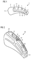
- FIG. 1 is a hearing aid 1, which is designed as a hearing aid device shown.
- the hearing device 1 comprises a housing 2 for enclosing electronic components of the hearing device 1.
- the electronic components are formed in the present embodiment by two microphones 4, a loudspeaker 6 and by a (signal transmission technology) between the two microphones 4 and the speaker 6 signal processing unit 8 , Furthermore, the electronic components comprise a circuit carrier not shown in detail on which a number of conductor tracks 10 for electrically contacting the microphones 4 and the loudspeaker 6 with the signal processing unit 8 are formed.
- the hearing aid 1 For mounting the microphones 4, the speaker 6 and the signal processing unit 8 (and the circuit substrate) in the housing 2, this comprises a base body 12 in which a mounting hole is formed, and a (shell-like) housing cover 14 for closing this mounting hole.
- the hearing aid 1 comprises a sealing body 18 (in FIG. 1 indicated by a dot-dash line). This sealing body 18 is arranged in the interior of the housing 2, the closing edge 16 overlapping.
- the sealing body 18 of the (shell) shape of the housing cover 12 is modeled. Consequently, the sealing body 18 also has a half-shell shape.
- the sealing body 18 is placed in this case during assembly as well as the housing cover 12 via the electronic components of the hearing aid 1.
- the sealing body 18 has two openings (correspondingly referred to as microphone passages 20) which correspond to the microphones 4 and which, in the intended installation state according to FIG FIG. 1 with two (not shown) microphone openings in the housing cover 12 are arranged in alignment.
- the seal body 18 in the present embodiment, openings for a "user interface" such. B. button (not shown) on. These openings are referred to below as interface passages 22.
- the hearing device 1 is also set up for wireless signal transmission with a separate from the hearing aid 1 electronic device.
- the hearing aid 1 comprises an antenna body 24, which is set up and provided for the reception of radio signals.
- This antenna body 24 is embedded in the sealing body 18, specifically cast by injection molding in this.
- the antenna body 24 has two tabs each referred to as contact portion 26, which are arranged in a (contact) window 28 of the seal body 18 and thus not embedded in the seal body 18.
- the contact portion 26 protrude from a lateral edge of the seal body 18.
- the antenna body 24 is in accordance with the intended mounting state FIG. 1 connected by means of these contact portions 26 via a solder connection to the circuit carrier.
- the antenna body 24 has a (similar to the sealing body 18 formed) three-dimensionally curved, sheet-like and sheet-like structure. Specifically, the antenna body 24 of a plurality of sheet-like - d. H. in comparison to the covered surface of thin, strip-shaped sections made of metal (copper). As a result, a large effective antenna area is formed with comparatively low material expenditure.
- the integration of the antenna body 24 into the sealing body 18 also improves the operability of the antenna body 24 during assembly since the sealing body 18 supports (i.e., supports) the sheet-like structure of the antenna body.
- the seal body 18 is injection molded from LSR (liquid silicone rubber). As a result, the sealing body 18 has a high temperature resistance, so that the sealing body 18 is not damaged during soldering of the contact portions 26.
- LSR liquid silicone rubber
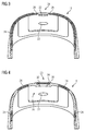
- FIG. 4 a further embodiment of the seal body 18 is shown.
- the sealing body 18 has two damping sections 30, each associated with one of the microphone passages 20.
- the damping sections 30 are local thickenings of the sealing body 18, by means of which the two microphones 4 are elastically resiliently supported against the housing cover 12.
- the hearing aid 1 in each case has a respective barrier element 32 associated with the respective microphone 4.
- This barrier element 32 is formed by a sound-permeable, hydrophobic membrane, which is spanned by an annular frame.
- the respective barrier element 32 is reversibly supported in the seal body 18 within the respective microphone passageway 20.
- the respective microphone passage 20 has an undercut, in which the respective barrier element 32 is used by utilizing the elastic deformation capacity of the housing cover 12 facing edge 34 of the respective microphone passage 20.
- the respective microphone 4 In the intended mounting state of the hearing aid 1 according to FIG. 1 is the respective microphone 4 from an inner side 36 of the seal body 18 to the respective damping portion 30 and presses the opposite edge 34 sealingly against the housing cover 12 at.
Abstract
Ein erfindungsgemäßes Hörgerät (1) umfasst ein Gehäuse (2), das eine Montageöffnung sowie einen Gehäusedeckel (14) zum Verschließen der Montageöffnung aufweist. Des Weiteren umfasst das Hörgerät (1) eine in dem Gehäuse (2) angeordnete Signalverarbeitungseinheit (8) und einen Dichtungskörper (18) zur Abdichtung des Gehäuses (2) gegen den Eintritt von Verunreinigungen. Außerdem umfasst das Hörgerät (1) einen Antennenkörper (24) zur drahtlosen Signalübertragung mit einem separaten Gerät. Dieser Antennenkörper (24) ist in den Dichtungskörper (18) eingebettet.An inventive hearing device (1) comprises a housing (2) which has a mounting opening and a housing cover (14) for closing the mounting opening. Furthermore, the hearing aid (1) comprises a signal processing unit (8) arranged in the housing (2) and a sealing body (18) for sealing the housing (2) against the entry of contaminants. In addition, the hearing aid (1) comprises an antenna body (24) for wireless signal transmission with a separate device. This antenna body (24) is embedded in the sealing body (18).
Description
Die Erfindung bezieht sich auf ein Hörgerät, insbesondere auf ein Hörhilfegerät.The invention relates to a hearing aid, in particular to a hearing aid.
Hörgeräte dienen üblicherweise der Ausgabe von (akustischen) Schallsignalen an ein Ohr oder das Hörzentrum des jeweiligen Hörgerätenutzers. Meist umfassen Hörgeräte dazu einen, häufig als "Hörer" bezeichneten, Lautsprecher, der unmittelbar im Gehörgang des jeweiligen Ohrs des Hörgerätenutzers getragen wird oder beispielsweise mittels eines Schallschlauchs mit diesem Gehörgang akustisch verbunden ist. Alternativ kann einem Hörgerät zur Übertragung des Schallsignals auch ein Knochenleitungsimplantat, ein Cochlea-Implantat oder dergleichen zugeordnet sein. In diesem Fall sind Hörgeräte insbesondere als Hörhilfegeräte zum Ausgleich einer Verminderung des Hörvermögens des Hörgerätenutzers ausgebildet und umfassen dabei meist zusätzlich wenigstens ein Mikrophon zur Erfassung von (Umgebungs-)Geräuschen sowie eine Signalverarbeitungseinheit, mittels derer die erfassten Geräusche gegebenenfalls gefiltert und anschließend verstärkt an den Lautsprecher ausgegeben werden. Alternativ kann es sich bei einem Hörgerät aber auch um einen sogenannten Tinitus-Masker handeln, mittels dessen ein für den Hörgerätenutzer spezifisches Hintergrund- oder Rausch-Signal erzeugt und ausgegeben wird.Hearing aids are usually used to output (acoustic) sound signals to an ear or the hearing center of the respective hearing device user. In most cases, hearing aids include a loudspeaker, often referred to as a "handset", which is worn directly in the auditory canal of the respective ear of the hearing device user or is acoustically connected, for example, by means of a sound tube to this auditory canal. Alternatively, a hearing aid for transmitting the sound signal may also be associated with a bone conduction implant, a cochlear implant or the like. In this case, hearing aids are designed in particular as hearing aids to compensate for a reduction in the hearing of the hearing device user and thereby usually additionally comprise at least one microphone for detecting (ambient) noise and a signal processing unit, by means of which the detected sounds optionally filtered and then amplified to the speaker be issued. Alternatively, a hearing device may also be a so-called tinnitus masker, by means of which a background or noise signal specific to the hearing device user is generated and output.
Moderne Hörgeräte weisen teilweise Mittel zur (drahtlosen) Kommunikation mit einem separaten Gerät auf. Bei einem solchen separaten Gerät handelt es sich meist um eine Steuereinheit, mittels derer (drahtlos) Verarbeitungseinstellungen auf das jeweilige Hörgerät übertragen werden können, oder auch - im Fall eines binauralen Hörgerätesystems zur Versorgung beider Ohren des Hörgerätenutzers - um ein zweites Hörgerät. Bei der Steuereinheit kann es sich wiederum beispielsweise um ein Smartphone handeln, auf dem eine Software-Applikation zur Steuerung des Hörgeräts installiert ist. Desweiteren kann es sich bei dem separaten Gerät auch um eine Audiosignalquelle handeln, die abzuspielende Audiosignale auf das Hörgerät überträgt, wie zum Beispiel ein TV-Gerät, ein Smartphone oder dergleichen. Bei solchen Audiosignalen handelt es sich beispielsweise um Musikstücke, die ansonsten über die Lautsprecher des TV-Geräts ausgegebenen Tonsignale oder - für den Fall, dass das Hörgerät ein Headset darstellt - auch um Sprachsignale eines Telefons.Modern hearing aids partly have means for (wireless) communication with a separate device. In such a separate device is usually a control unit by means of which (wireless) processing settings can be transferred to the respective hearing aid, or - in the case of a binaural hearing aid system for supplying both ears of the hearing device user - to a second hearing aid. The control unit may again be, for example to act a smartphone on which a software application for controlling the hearing aid is installed. Furthermore, the separate device may also be an audio signal source which transmits audio signals to be played back to the hearing aid, such as a TV set, a smartphone or the like. Such audio signals are, for example, pieces of music which are otherwise sound signals output via the loudspeakers of the TV set or, in the case in which the hearing device is a headset, also voice signals of a telephone.
Erkanntermaßen sind zur drahtlosen Kommunikation (Signalübertragung) als Antenne dienende elektrisch leitfähige Bauteile in dem Hörgerät erforderlich. Diese werden üblicherweise durch metallische Strukturen gebildet, insbesondere durch auf einer Leiterplatte angeordnete Leiterbahnen. Dabei können diese Strukturen in einem die Signalverarbeitungseinheit tragenden Schaltungsträger integriert oder galvanisch mit diesem verbunden sein. Vor dem Hintergrund einer fortschreitenden Miniaturisierung von Hörgeräten, ist jedoch oft der Bauraumbedarf sowie die Montage einer separaten Antenne problematisch.It is known that for wireless communication (signal transmission) as an antenna serving electrically conductive components in the hearing aid is required. These are usually formed by metallic structures, in particular arranged on a printed circuit board tracks. In this case, these structures can be integrated in a signal carrier carrying the signal processing unit or galvanically connected thereto. Against the background of a progressive miniaturization of hearing aids, however, often the space requirement and the installation of a separate antenna is problematic.
Der Erfindung liegt die Aufgabe zugrunde, ein zur drahtlosen Kommunikation eingerichtetes Hörgerät zu verbessern.The invention has for its object to improve a set up for wireless communication hearing aid.
Diese Aufgabe wird erfindungsgemäß gelöst durch ein Hörgerät mit den Merkmalen des Anspruchs 1. Vorteilhafte und teils für sich erfinderische Ausführungsformen und Weiterentwicklungen der Erfindung sind in den Unteransprüchen und der nachfolgenden Beschreibung dargelegt.This object is achieved by a hearing aid with the features of claim 1. Advantageous and partly inventive embodiments and further developments of the invention are set forth in the dependent claims and the description below.
Bei dem erfindungsgemäßen Hörgerät handelt es sich vorzugsweise um ein Hörhilfegerät. Das Hörgerät umfasst dabei ein Gehäuse, das eine Montageöffnung sowie einen Gehäusedeckel zum Verschließen dieser Montageöffnung aufweist. Das Hörgerät umfasst des Weiteren eine Signalverarbeitungseinheit, die in dem Gehäuse angeordnet ist, sowie einen Dichtungskörper zur Abdichtung des Gehäuses gegen den Eintritt von Verunreinigungen, wie zum Beispiel Flüssigkeit, Ohrenschmalz, Staub etc. Der Dichtungskörper ist dabei vorzugsweise dazu eingerichtet und vorgesehen, das Gehäuse von dessen Innenseite her abzudichten. Das heißt, dass der Dichtungskörper im bestimmungsgemäßen Montagezustand des Hörgeräts - also bei geschlossenem Gehäuse - im Innenraum des Gehäuses angeordnet und vorzugsweise von der Außenseite des Hörgeräts nicht sichtbar ist. Das Hörgerät umfasst außerdem einen Antennenkörper zur drahtlosen Kommunikation (d. h. Signalübertragung) mit einem (von dem Hörgerät) separaten, vorzugsweise elektronischen Gerät. Dieser Antennenkörper ist dabei in den Dichtungskörper eingebettet (d.h. in diesen integriert).The hearing aid according to the invention is preferably a hearing aid. The hearing aid comprises a housing which has a mounting opening and a housing cover for closing this mounting opening. The hearing device further comprises a signal processing unit, which is arranged in the housing, as well as a sealing body for sealing the housing against the entry of impurities, such as liquid, earwax, dust, etc. The sealing body is preferably arranged thereto and provided to seal the housing from the inside thereof. This means that the sealing body in the intended mounting state of the hearing aid - that is, when the housing is closed - arranged in the interior of the housing and is preferably not visible from the outside of the hearing aid. The hearing device also comprises an antenna body for wireless communication (ie signal transmission) with a (preferably separate from the hearing device), preferably electronic device. This antenna body is embedded in the sealing body (ie integrated in this).
Bei dem separaten Gerät handelt es sich beispielsweise um eine Steuereinheit, die dazu eingerichtet und vorgesehen ist, Einstellungsparameter für die Signalverarbeitungseinheit drahtlos an das Hörgerät zu übertragen. Alternativ handelt es sich bei dem separaten Gerät um ein zweites, binaurales Hörgerät oder um ein elektronisches Gerät, das Audiosignale drahtlos an das Hörgerät überträgt, wie beispielsweise ein Smartphone, ein TV-Gerät oder dergleichen.The separate device is, for example, a control unit which is set up and provided to transmit setting parameters for the signal processing unit wirelessly to the hearing aid. Alternatively, the separate device is a second, binaural hearing device or an electronic device that transmits audio signals wirelessly to the hearing aid, such as a smartphone, a TV set or the like.
Die Signalverarbeitungseinheit dient vorzugsweise zur Verarbeitung, d. h. beispielsweise zur Auswertung, Filterung, Analog-Digital-Wandlung und dergleichen, der mittels des Antennenkörpers empfangenen Signale ("Funksignale"). Des Weiteren dient die Signalverarbeitungseinheit insbesondere auch zur Verarbeitung von Schallsignalen, die mittels eines gegebenenfalls von dem Hörgerät umfassten Mikrophons erfasst werden. Die Signalverarbeitungseinheit ist insbesondere als nicht-programmierbare elektronische Schaltung (z. B. als ASIC) ausgebildet. Alternativ ist die Signalverarbeitungseinheit durch einen Mikrocontroller gebildet, in dem die Funktionalität zur Durchführung der Signalverarbeitung in Form eines Softwaremoduls implementiert ist.The signal processing unit is preferably for processing, d. H. for example, for evaluation, filtering, analog-to-digital conversion and the like, the signals received by means of the antenna body ("radio signals"). Furthermore, the signal processing unit is also used in particular for processing sound signals which are detected by means of a microphone which may be included in the hearing aid. The signal processing unit is designed in particular as a non-programmable electronic circuit (eg ASIC). Alternatively, the signal processing unit is formed by a microcontroller in which the functionality for carrying out the signal processing in the form of a software module is implemented.
Die Integration des Antennenkörpers in den Dichtungskörper führt zu einer Reduktion der Anzahl von bei der Montage des Hörgeräts handzuhabenden Einzelteilen. Dadurch wird vorteilhafterweise Montageaufwand eingespart. Des Weiteren kann vorteilhafterweise auch Bauraum eingespart werden.The integration of the antenna body in the seal body leads to a reduction in the number of handled during assembly of the hearing aid items. As a result, assembly effort is saved advantageously. Furthermore, advantageously, space can also be saved.
In einer zweckmäßigen Ausführung weist der Antennenkörper eine flächige, folienartige Struktur auf. "Folienartig" bedeutet hier und im Folgenden, dass die Wanddicke des Antennenkörpers im Vergleich zu seiner Flächenausdehnung klein ist. Die Fläche des Antennenkörpers ist dabei vorzugsweise derart groß gewählt, dass auch vergleichsweise schwache Funksignale empfangen werden können. Vorzugsweise nimmt die von dem Antennenkörper abgedeckte Fläche etwa die Hälfte oder drei Viertel der von dem Gehäuse, insbesondere von dem Gehäusedeckel abgedeckten Fläche ein. Aufgrund der folienartigen Struktur weist der Antennenkörper erkanntermaßen eine geringe dimensionale Stabilität auf (d. h. dieser kann bei der Handhabung in sich zusammenfallen oder leicht beschädigt werden), so dass aufgrund der Integration in den Dichtungskörper die Stabilität und Handhabbarkeit des Antennenkörpers vorteilhafterweise erhöht wird.In an expedient embodiment, the antenna body has a flat, foil-like structure. "Film-like" means here and below that the wall thickness of the antenna body is small compared to its surface area. The surface of the antenna body is preferably chosen so large that even comparatively weak radio signals can be received. Preferably, the area covered by the antenna body occupies about half or three quarters of the area covered by the housing, in particular by the housing cover. Due to the film-like structure, the antenna body is known to have a low dimensional stability (i.e., it may collapse or be easily damaged during handling), so that the stability and manageability of the antenna body is advantageously increased due to integration into the seal body.
Zweckmäßigerweise ist der Antennenkörper aus einem Metall, insbesondere aus Kupfer gebildet. Dadurch wird eine besonders gute elektrische Leitfähigkeit und damit auch eine hohe Empfangsqualität ermöglicht.The antenna body is expediently formed from a metal, in particular from copper. This allows a particularly good electrical conductivity and thus also a high reception quality.
In einer bevorzugten Ausführung ist der Antennenkörper mit einem den Dichtungskörper bildenden Kunststoff, insbesondere einem Elastomer umspritzt. Das heißt, dass der Antennenkörper ein Einlegeteil bildet, das in einem Spritzgießverfahren mit dem Kunststoff des Dichtungskörpers umhüllt wird. Bei dem Kunststoff handelt es sich vorzugsweise um ein spritzgießfähiges Flüssigsilikon (englisch auch als "liquid silicone rubber" bezeichnet, kurz: LSR).In a preferred embodiment, the antenna body is encapsulated with a plastic forming the sealing body, in particular an elastomer. That is, the antenna body forms an insert which is wrapped in an injection molding with the plastic of the seal body. The plastic is preferably an injection-moldable liquid silicone (also known as "liquid silicone rubber", in short: LSR).
In einer weiteren zweckmäßigen Ausführung ist der Dichtungskörper insbesondere halbschalenartig ausgebildet, so dass dieser im bestimmungsgemäßen Montagezustand die Signalverarbeitungseinheit, vorzugsweise wenigstens eine Seite eines die Signalverarbeitungseinheit und gegebenenfalls eine Anzahl von Leiterbahnen tragenden Schaltungsträgers, ganz oder zumindest teilweise haubenartig überdeckt. Die Form des Dichtungskörpers ist dabei vorzugsweise an die Form des Gehäusedeckels angeglichen. Der Dichtungskörper ist somit derart gestaltet, dass dieser bei der Montage ähnlich wie der Gehäusedeckel über die in dem Gehäuse angeordnete Signalverarbeitungseinheit (bzw. den dort angeordneten Schaltungsträger) aufgesetzt wird und anschließend mit dem Gehäusedeckel abgedeckt wird. Dadurch wird eine besonders einfache Montage des Dichtungskörpers, sowie des Antennenkörpers ermöglicht. Der Antennenkörper nimmt hierbei etwa wenigstens die Hälfte der Fläche des Dichtungskörpers ein. Der Antennenkörper weist dadurch eine hinsichtlich der Empfangsqualität von Funksignalen vorteilhafte, dreidimensional gewölbte Struktur sowie vorteilhafterweise eine vergleichsweise große Oberfläche auf.In a further expedient embodiment, the sealing body is in particular of a half-shell-like design so that it covers the signal processing unit, preferably at least one side of a circuit carrier supporting the signal processing unit and possibly a number of printed conductors, completely or at least partially like a hood in the intended mounting state. The shape of the sealing body is preferably adapted to the shape of the housing cover. The sealing body is thus designed in such a way that, during assembly, it is similar to the housing cover via the signal processing unit (or the circuit carrier arranged there) in the housing. is placed on and then covered with the housing cover. As a result, a particularly simple assembly of the sealing body, as well as the antenna body is made possible. In this case, the antenna body occupies approximately at least half the area of the sealing body. As a result, the antenna body has a three-dimensionally curved structure which is advantageous with regard to the reception quality of radio signals, and advantageously has a comparatively large surface area.
In einer bevorzugten Ausführung weist der Antennenkörper einen freiliegenden, d. h. nicht mit Kunststoff umspritzten, Kontaktabschnitt auf, mittels dessen der Antennenkörper vorzugsweise durch eine Lötverbindung mit der Signalverarbeitungseinheit, insbesondere mittelbar über eine Leiterbahn des Schaltungsträgers, kontaktiert ist. Im Fall einer Lötverbindung ist der Einsatz eines LSR als Material für den Dichtungskörper besonders zweckmäßig, da ein solches Flüssigsilikon regelmäßig eine im Vergleich zu herkömmlichen spritzgießfähigen Elastomeren hohe Temperaturbeständigkeit aufweist und somit während des Lötvorgangs nicht beschädigt wird. Alternativ zu der Lötverbindung ist der Antennenkörper beispielsweise mittels einer Klemmverbindung, einer Steckverbindung oder einem Federkontakt mit der Signalverarbeitungseinheit kontaktiert. In letzterem Fall ist es im Rahmen der Erfindung denkbar, dass der Antennenkörper nur auf einer Innenseite des Dichtungskörpers an einem Teilbereich seiner Fläche freiliegt. Im bestimmungsgemäßen Montagezustand steht dieser freiliegende Teilbereich mit der korrespondierenden Kontaktfeder in Kontakt. Im Fall einer federbelasteten Kontaktierung wird der Antennenkörper außerdem vorzugsweise über den Dichtungskörper gegen das Gehäuse abgestützt, sodass eine zuverlässige elektrische Kontaktierung mittels des Federkontakts ermöglicht ist. Im Rahmen der Erfindung ist es ferner aber auch denkbar, dass der Antennenkörper vollständig in den Dichtungskörper integriert ist und somit an keiner Stelle freiliegt. In diesem Fall ist der Antennenkörper über einen spitzen Kontaktstift mit der Signalverarbeitungseinheit kontaktiert. Dieser Kontaktstift durchsticht bei der Montage des Dichtungskörpers diesen zumindest innenseitig und steht somit mit dem Antennenkörper in galvanischem Kontakt. Ferner ist im Rahmen der Erfindung auch eine induktive oder kapazitive, d. h. nicht galvanische, Kopplung der Antenne mit der Signalverarbeitungseinheit möglich. In diesem Fall ist insbesondere keine feste Verbindung zwischen dem Antennenkörper und der Signalverarbeitungseinheit vorhanden.In a preferred embodiment, the antenna body has an exposed, ie not overmolded with plastic, contact portion, by means of which the antenna body is preferably contacted by a solder connection to the signal processing unit, in particular indirectly via a conductor track of the circuit carrier. In the case of a solder joint, the use of an LSR as the material for the sealing body is particularly useful because such a liquid silicone regularly has a high temperature resistance compared to conventional injection moldable elastomers and thus is not damaged during the soldering process. As an alternative to the solder joint, the antenna body is contacted to the signal processing unit, for example, by means of a clamping connection, a plug connection or a spring contact. In the latter case, it is conceivable within the scope of the invention for the antenna body to be exposed only on an inner side of the sealing body at a partial area of its surface. In the intended mounting state, this exposed portion is in contact with the corresponding contact spring. In the case of a spring-loaded contacting the antenna body is also preferably supported via the sealing body against the housing, so that a reliable electrical contact is made possible by means of the spring contact. In the context of the invention, however, it is also conceivable that the antenna body is completely integrated in the sealing body and thus exposed at any point. In this case, the antenna body is contacted via a pointed contact pin with the signal processing unit. This contact pin pierces during assembly of the seal body this at least on the inside and thus is in galvanic contact with the antenna body. Furthermore, within the scope of the invention, an inductive or capacitive, ie not galvanic, coupling of the antenna with the signal processing unit possible. In this case, in particular, there is no fixed connection between the antenna body and the signal processing unit.
In einer zweckmäßigen Ausführung umfasst das Hörgerät wenigstens ein Mikrophon zur Erfassung von akustischen Signalen vorzugsweise aus der Umgebung des Hörgeräts. In diesem Fall weist der Dichtungskörper vorzugsweise einen Dämpfungsabschnitt zur elastischen Abstützung des jeweiligen Mikrophons gegen das Gehäuse auf. Bei diesem Dämpfungsabschnitt handelt es sich vorzugsweise um einen Bereich des Dichtungskörpers mit einer erhöhten Wandstärke, d. h. um eine Verdickung des Dichtungskörpers. Durch die elastische Abstützung des jeweiligen Mikrophons werden vorteilhafterweise Vibrationen des Mikrophons selbst verringert sowie eine Übertragung von Körperschall, d. h. Schwingungen des Gehäuses oder anderer Komponenten des Hörgeräts, auf das jeweilige Mikrophon unterbunden oder zumindest verringert. Durch die Integration einer Dämpfungsfunktion in den Dichtungskörper kann vorteilhafterweise die Einzelteilanzahl des Hörgeräts weiter reduziert und so Montageaufwand eingespart werden.In an expedient embodiment, the hearing device comprises at least one microphone for the detection of acoustic signals, preferably from the surroundings of the hearing device. In this case, the sealing body preferably has a damping portion for the elastic support of the respective microphone against the housing. This damping section is preferably a region of the sealing body with an increased wall thickness, i. H. to a thickening of the seal body. Due to the elastic support of the respective microphone vibrations of the microphone itself are advantageously reduced and a transmission of structure-borne noise, d. H. Vibrations of the housing or other components of the hearing aid, prevented or at least reduced to the respective microphone. By integrating a damping function in the sealing body advantageously the number of parts of the hearing aid can be further reduced and so assembly effort can be saved.
In einer bevorzugten Weiterbildung ist in einem dem Mikrophon im bestimmungsgemäßen Montagezustand nächstliegenden Bereich des Gehäuses, insbesondere in dem Gehäusedeckel, eine zu dem jeweiligen Mikrophon korrespondierende Mikrophonöffnung angeordnet. Durch diese Mikrophonöffnung kann das aus der Umgebung stammende akustische Signal (Schallsignal) nahezu ungedämpft auf das jeweilige Mikrophon treffen. Zweckmäßigerweise weist hierbei auch der Dichtungskörper im Bereich des jeweiligen Dämpfungsabschnitts, vorzugsweise innerhalb des jeweiligen Dämpfungsabschnitts, einen Durchbruch auf, der (im bestimmungsgemäßen Montagezustand) korrespondierend zu der jeweiligen Mikrophonöffnung angeordnet und ausgebildet ist. Der Dämpfungsabschnitt liegt hierbei zweckmäßigerweise ringförmig um die jeweilige Mikrophonöffnung herum an dem Gehäuse, insbesondere an dem Gehäusedeckel an.In a preferred development, a microphone opening corresponding to the respective microphone is arranged in a region of the housing closest to the microphone in the intended mounting state, in particular in the housing cover. By virtue of this microphone opening, the acoustic signal originating from the environment (sound signal) can strike the respective microphone virtually unattenuated. Expediently, the sealing body also has an opening in the area of the respective damping section, preferably within the respective damping section, which opening (in the intended mounting state) is arranged and designed corresponding to the respective microphone opening. The damping section here expediently lies annularly around the respective microphone opening on the housing, in particular on the housing cover.
In einer zweckmäßigen Weiterbildung ist in dem oder jedem (Mikrophon-)Durchbruch des Dichtungskörpers ein vorzugsweise hydrophobes und schalldurchlässiges Barriereelement zum Schutz des jeweiligen Mikrophons vor Feuchtigkeit und sonstige Verunreinigungen angeordnet. Das Barriereelement umfasst vorzugsweise eine "atmungsaktive" Membran, die insbesondere aus einem feinporösen (netz- oder vliesartigen) und hydrophoben oder hydrophob beschichteten Material gebildet ist. Optional ist die Membran auch wasserdicht, beispielsweise in Form einer Kunststofffolie aus Polyetherester oder mikroporösem Polytetrafluorethen (kurz: PTFE). Das jeweilige Barriereelement ist hierbei insbesondere austauschbar in dem Durchbruch angeordnet, d. h. das Barriereelement kann zu Reinigungs- oder Reparaturzwecken entnommen werden. Dazu weist der jeweilige Durchbruch vorzugsweise einen Hinterschnitt auf, der eine Tasche für das Barriereelement bildet. In diesem Hinterschnitt ist das jeweilige Barriereelement vorzugsweise formschlüssig gehaltert. Zum Einsetzen in den jeweiligen Hinterschnitt wird das Barriereelement dabei vorzugsweise über einen den Hinterschnitt begrenzenden Rand des Durchbruchs in den Hinterschnitt eingedrückt. Der jeweilige Rand wird dabei elastisch deformiert und "schnappt" anschließend über das Barriereelement zurück, so dass dieses formschlüssig in dem Hinterschnitt einliegt. Durch diese Weiterbildung weist der Dichtungskörper eine besonders hohe Funktionsintegration auf, so dass der Montageaufwand weiter reduziert werden kann.In an expedient development is in the or each (microphone) breakthrough of the seal body, a preferably hydrophobic and sound-permeable barrier element to protect the respective microphone from moisture and arranged other impurities. The barrier element preferably comprises a "breathable" membrane which is formed, in particular, from a finely porous (mesh or fleece-like) and hydrophobic or hydrophobically coated material. Optionally, the membrane is also waterproof, for example in the form of a plastic film of polyetherester or microporous polytetrafluoroethene (short: PTFE). In this case, the respective barrier element is arranged interchangeably in particular in the opening, ie the barrier element can be removed for cleaning or repair purposes. For this purpose, the respective opening preferably has an undercut, which forms a pocket for the barrier element. In this undercut, the respective barrier element is preferably held positively. For insertion into the respective undercut, the barrier element is preferably pressed into the undercut via an edge of the opening which delimits the undercut. The respective edge is elastically deformed and then "snaps" back over the barrier element, so that this rests positively in the undercut. As a result of this development, the sealing body has a particularly high functional integration, so that the assembly effort can be further reduced.
Nachfolgend werden Ausführungsbeispiele der Erfindung anhand einer Zeichnung näher erläutert. Darin zeigen:
- FIG 1
- in schematischer Seitenansicht ein Hörgerät,
- FIG 2
- in einer schematischen Perspektivdarstellung einen Dichtungskörper des Hörgeräts gemäß
FIG 1 mit einem darin integrierten Antennenkör-per, - FIG 3
- in einer Schnittdarstellung den Dichtungskörper gemäß
FIG 2 , und - FIG 4
- in Ansicht gemäß
FIG 3 ein weiteres Ausführungsbeispiel des Dich-tungskörpers.
- FIG. 1
- in a schematic side view of a hearing aid,
- FIG. 2
- in a schematic perspective view of a sealing body of the hearing aid according to
FIG. 1 with an antenna body integrated therein, - FIG. 3
- in a sectional view of the seal body according to
FIG. 2 , and - FIG. 4
- in view according to
FIG. 3 a further embodiment of the sealing body.
Einander entsprechende Teile sind in allen Figuren stets mit gleichen Bezugszeichen versehen.Corresponding parts are always provided with the same reference numerals in all figures.
In
Wie in
Das Hörgerät 1 ist außerdem zur drahtlosen Signalübertragung mit einem von dem Hörgerät 1 separaten elektronischen Gerät eingerichtet. Dazu umfasst das Hörgerät 1 einen Antennenkörper 24, der zum Empfang von Funksignalen eingerichtet und vorgesehen ist. Dieser Antennenkörper 24 ist in den Dichtungskörper 18 eingebettet, konkret spritzgießtechnisch in diesen eingegossen. Zur Kontaktierung des Antennenkörpers 24 mit dem Schaltungsträger und damit mit der Signalverarbeitungseinheit 8 weist der Antennenkörper 24 zwei jeweils als Kontaktabschnitt 26 bezeichnete Laschen auf, die in einem (Kontakt-)Fenster 28 des Dichtungskörpers 18 angeordnet und somit nicht in den Dichtungskörper 18 eingebettet sind. In einem alternativen, nicht näher dargestellten Ausführungsbeispiel ragen die Kontaktabschnitt 26 aus einem seitlichen Rand des Dichtungskörpers 18 hervor. Der Antennenkörper 24 ist im bestimmungsgemäßen Montagezustand gemäß
Der Antennenkörper 24 weist eine (ähnlich zu dem Dichtungskörper 18 ausgebildete) dreidimensional gewölbte, flächige und folienartige Struktur auf. Konkret ist der Antennenkörper 24 aus mehreren folienartigen - d. h. im Vergleich zur abgedeckten Fläche dünnen -, streifenförmigen Abschnitten aus Metall (Kupfer) gebildet. Dadurch ist mit vergleichsweise geringem Materialaufwand eine große wirksame Antennenfläche gebildet. Durch die Integration des Antennenkörpers 24 in den Dichtungskörper 18 wird außerdem die Handhabbarkeit des Antennenkörpers 24 bei der Montage verbessert, da der Dichtungskörper 18 die folienartige Struktur des Antennenkörpers trägt (d. h. stützt).The
Der Dichtungskörper 18 ist aus einem LSR (Flüssigsilikonkautschuk) spritzgegossen. Dadurch weist der Dichtungskörper 18 eine hohe Temperaturbeständigkeit auf, sodass der Dichtungskörper 18 beim Löten der Kontaktabschnitte 26 nicht beschädigt wird.The
In
Der Gegenstand der Erfindung ist nicht auf die vorstehend beschriebenen Ausführungsbeispiele beschränkt. Vielmehr können weitere Ausführungsformen der Erfindung von dem Fachmann aus der vorstehenden Beschreibung abgeleitet werden. Insbesondere können die anhand der verschiedenen Ausführungsbeispiele beschriebenen Einzelmerkmale der Erfindung und deren Ausgestaltungsvarianten auch in anderer Weise miteinander kombiniert werden.The object of the invention is not limited to the embodiments described above. Rather, other embodiments of the invention may be derived by those skilled in the art from the foregoing description. In particular, the individual features of the invention described with reference to the various exemplary embodiments and their design variants can also be combined with one another in a different manner.
- 11
- Hörgeräthearing Aid
- 22
- Gehäusecasing
- 44
- Mikrophonmicrophone
- 66
- Lautsprecherspeaker
- 88th
- SignalverarbeitungseinheitSignal processing unit
- 1010
- Leiterbahnconductor path
- 1212
- Grundkörperbody
- 1414
- Gehäusedeckelhousing cover
- 1616
- Schließkanteclosing edge
- 1818
- Dichtungskörperseal body
- 2020
- MikrophondurchgangMicrophone passage
- 2222
- InterfacedurchgangInterface passage
- 2424
- Antennenkörperantenna body
- 2626
- KontaktabschnittContact section
- 2828
- Kontaktfenstercontact window
- 3030
- Dichtungsabschnittsealing section
- 3232
- Barriereelementbarrier member
- 3434
- Randedge
- 3636
- Innenseiteinside
Claims (8)
wobei der Antennenkörper (24) eine flächige, folienartige Struktur aufweist.Hearing aid (1) according to claim 1,
wherein the antenna body (24) has a flat, foil-like structure.
wobei der Antennenkörper (24) mit einem den Dichtungskörper (18) bildenden Kunststoff, insbesondere einem Elastomer umspritzt ist.Hearing aid (1) according to claim 1 or 2,
wherein the antenna body (24) with a sealing body (18) forming plastic, in particular an elastomer is overmolded.
wobei der Dichtungskörper (18) halbschalenartig ausgebildet ist, so dass der Dichtungskörper (18) im bestimmungsgemäßen Montagezustand die Signalverarbeitungseinheit (8) wenigstens teilweise haubenartig überdeckt.Hearing aid (1) according to one of claims 1 to 3,
wherein the sealing body (18) is formed like a half shell, so that the sealing body (18) covers the signal processing unit (8) at least partially like a hood in the intended mounting state.
wobei der Antennenkörper (24) einen freiliegenden Kontaktabschnitt (26) aufweist, mittels dessen der Antennenkörper (24) über eine Lötverbindung mit der Signalverarbeitungseinheit (8) kontaktiert ist.Hearing aid (1) according to one of claims 1 to 4,
wherein the antenna body (24) has an exposed contact portion (26), by means of which the antenna body (24) via a solder connection with the signal processing unit (8) is contacted.
mit wenigstens einem Mikrophon (4) zur Erfassung von akustischen Signalen, wobei der Dichtungskörper (18) wenigstens einen Dämpfungsabschnitt (30) zur elastischen Abstützung des jeweiligen Mikrophons (4) gegen das Gehäuse (2) aufweist.Hearing aid (1) according to one of claims 1 to 5,
with at least one microphone (4) for detecting acoustic signals, wherein the sealing body (18) has at least one damping section (30) for elastic support of the respective microphone (4) against the housing (2).
wobei in dem Gehäuse (2) eine zu dem jeweiligen Mikrophon (4) korrespondierende Mikrophonöffnung angeordnet ist, wobei der Dichtungskörper (18) im Bereich des jeweiligen Dämpfungsabschnitts (30) einen im bestimmungsgemäßen Montagezustand mit der jeweiligen Mikrophonöffnung korrespondierenden Durchbruch (20) aufweist.Hearing aid (1) according to claim 6,
wherein in the housing (2) to the respective microphone (4) corresponding microphone opening is arranged, wherein the sealing body (18) in the region of the respective damping portion (30) in the intended mounting state with the respective microphone opening corresponding aperture (20).
wobei in dem jeweiligen Durchbruch (20) ein Barriereelement (32) zum Schutz des jeweiligen Mikrophons (4) vor Feuchtigkeit reversibel einsetzbar angeordnet ist.Hearing aid (1) according to claim 7,
wherein in the respective opening (20) a barrier element (32) for the protection of the respective microphone (4) is arranged reversibly used against moisture.
Applications Claiming Priority (1)
| Application Number | Priority Date | Filing Date | Title |
|---|---|---|---|
| DE102015208845.6A DE102015208845B3 (en) | 2015-05-13 | 2015-05-13 | hearing Aid |
Publications (2)
| Publication Number | Publication Date |
|---|---|
| EP3094111A1 true EP3094111A1 (en) | 2016-11-16 |
| EP3094111B1 EP3094111B1 (en) | 2018-06-13 |
Family
ID=55646496
Family Applications (1)
| Application Number | Title | Priority Date | Filing Date |
|---|---|---|---|
| EP16163558.6A Active EP3094111B1 (en) | 2015-05-13 | 2016-04-01 | Hearing aid |
Country Status (5)
| Country | Link |
|---|---|
| US (1) | US9877122B2 (en) |
| EP (1) | EP3094111B1 (en) |
| CN (1) | CN106162479B (en) |
| DE (1) | DE102015208845B3 (en) |
| DK (1) | DK3094111T3 (en) |
Cited By (2)
| Publication number | Priority date | Publication date | Assignee | Title |
|---|---|---|---|---|
| EP3393142A1 (en) * | 2017-04-21 | 2018-10-24 | Starkey Laboratories, Inc. | Hearing assistance device incorporating a quarter wave stub as a solderless antenna connection |
| US11122376B2 (en) | 2019-04-01 | 2021-09-14 | Starkey Laboratories, Inc. | Ear-worn electronic device incorporating magnetically coupled feed for an antenna |
Families Citing this family (15)
| Publication number | Priority date | Publication date | Assignee | Title |
|---|---|---|---|---|
| DE102015208845B3 (en) * | 2015-05-13 | 2016-08-11 | Sivantos Pte. Ltd. | hearing Aid |
| US10051388B2 (en) | 2016-09-21 | 2018-08-14 | Starkey Laboratories, Inc. | Radio frequency antenna for an in-the-ear hearing device |
| US10256529B2 (en) | 2016-11-15 | 2019-04-09 | Starkey Laboratories, Inc. | Hearing device incorporating conformal folded antenna |
| CN106878871B (en) * | 2017-04-11 | 2019-09-10 | 英华达(上海)科技有限公司 | Audio electronics device and its operating method |
| US11116984B2 (en) | 2017-09-08 | 2021-09-14 | Advanced Bionics Ag | Extended length antenna assembly for use within a multi-component system |
| EP3471201B1 (en) | 2017-10-16 | 2021-02-17 | Widex A/S | Antenna for a hearing assistance device |
| DK3471198T3 (en) | 2017-10-16 | 2021-01-11 | Widex As | ANTENNA FOR A HEARING SUPPORT DEVICE |
| EP3471199A1 (en) | 2017-10-16 | 2019-04-17 | Widex A/S | Antenna for a hearing assistance device |
| EP3471200B1 (en) | 2017-10-16 | 2020-04-01 | Widex A/S | Antenna for a hearing assistance device |
| WO2019076570A1 (en) | 2017-10-16 | 2019-04-25 | Widex A/S | Antenna for a hearing assistance device |
| DE102017219470A1 (en) * | 2017-11-02 | 2019-05-02 | Sivantos Pte. Ltd. | hearing Aid |
| US20200021905A1 (en) * | 2018-07-10 | 2020-01-16 | New Audio LLC | Wireless earpiece having antenna with wall-embedded radiating element and related technology |
| WO2020140456A1 (en) | 2019-01-05 | 2020-07-09 | 深圳市韶音科技有限公司 | Loudspeaker device |
| CN109769167A (en) * | 2019-01-05 | 2019-05-17 | 深圳市韶音科技有限公司 | Osteoacusis loudspeaker arrangement |
| EP3817401A1 (en) | 2019-10-30 | 2021-05-05 | GN Hearing A/S | Hearing device |
Citations (3)
| Publication number | Priority date | Publication date | Assignee | Title |
|---|---|---|---|---|
| DE102004017832B3 (en) * | 2004-04-13 | 2005-10-20 | Siemens Audiologische Technik | hearing Aid |
| DE102005012149B3 (en) * | 2005-03-16 | 2006-09-21 | Siemens Audiologische Technik Gmbh | Covering device for at least one microphone input of a hearing device and hearing aid with a cover device |
| DE102011009860A1 (en) * | 2011-01-31 | 2012-08-02 | Heraeus Precious Metals Gmbh & Co. Kg | Implantable device with integrated ceramic bushing |
Family Cites Families (45)
| Publication number | Priority date | Publication date | Assignee | Title |
|---|---|---|---|---|
| US6046707A (en) * | 1997-07-02 | 2000-04-04 | Kyocera America, Inc. | Ceramic multilayer helical antenna for portable radio or microwave communication apparatus |
| JP2002537665A (en) * | 1999-06-16 | 2002-11-05 | フォーナック アーゲー | Hearing aid mounted behind the ear and method of assembling the same |
| DE10115896C2 (en) * | 2001-03-30 | 2003-12-24 | Siemens Audiologische Technik | Transmitter and / or receiver unit, which can be releasably connected to a hearing aid, and a programmable hearing aid |
| NL1030649C2 (en) * | 2005-12-12 | 2007-06-13 | Exsilent Res Bv | Hearing aid. |
| US7899200B2 (en) * | 2006-06-02 | 2011-03-01 | Phonak Ag | Universal-fit hearing device |
| DE102006026785A1 (en) * | 2006-06-07 | 2007-12-13 | Siemens Audiologische Technik Gmbh | Cover device for hearing aid housing arrangement |
| EP1915032B1 (en) * | 2006-10-18 | 2012-01-04 | Siemens Audiologische Technik GmbH | Hearing-aid |
| DE102007007800B3 (en) * | 2007-02-16 | 2008-08-28 | Siemens Audiologische Technik Gmbh | Hearing device with receiver compensation coil |
| US8325958B2 (en) * | 2007-08-10 | 2012-12-04 | Siemens Medical Instruments Pte. Ltd. | Hearing apparatus with pressure equalization for converters |
| US8265316B2 (en) * | 2008-03-20 | 2012-09-11 | Siemens Medical Instruments Pte. Ltd. | Hearing aid with enhanced vent |
| EP2279629A1 (en) * | 2008-04-01 | 2011-02-02 | Audiodent Israel Ltd. | Antenna arrangement for a hearing instrument |
| JP4355359B1 (en) * | 2008-05-27 | 2009-10-28 | パナソニック株式会社 | Hearing aid with a microphone installed in the ear canal opening |
| US20150227829A1 (en) * | 2008-08-29 | 2015-08-13 | David Finn | Laminates for security documents |
| US8379897B2 (en) * | 2008-09-17 | 2013-02-19 | Daniel R. Schumaier | Hearing assistance device having reduced mechanical feedback |
| US8437860B1 (en) * | 2008-10-03 | 2013-05-07 | Advanced Bionics, Llc | Hearing assistance system |
| CN101744674B (en) * | 2008-12-16 | 2011-06-15 | 上海冠芯电子科技有限公司 | Wholly sealed structure for artificial cochlea implanting device |
| US8737658B2 (en) * | 2008-12-19 | 2014-05-27 | Starkey Laboratories, Inc. | Three dimensional substrate for hearing assistance devices |
| US8798298B1 (en) * | 2008-12-31 | 2014-08-05 | Starkey Laboratories, Inc. | Constrained layer damping for hearing assistance devices |
| EP2219392B1 (en) * | 2009-02-17 | 2018-05-16 | Sivantos Pte. Ltd. | Microphone module for a hearing device |
| JP5366302B2 (en) * | 2009-04-30 | 2013-12-11 | パナソニック株式会社 | Mobile phone |
| JP2010278750A (en) * | 2009-05-28 | 2010-12-09 | Panasonic Corp | Portable wireless device |
| US8331594B2 (en) * | 2010-01-08 | 2012-12-11 | Sonic Innovations, Inc. | Hearing aid device with interchangeable covers |
| EP2548383B1 (en) * | 2010-03-19 | 2014-04-16 | Advanced Bionics AG | Waterproof acoustic element enclosure and apparatus including the same. |
| WO2011118379A1 (en) * | 2010-03-24 | 2011-09-29 | 株式会社村田製作所 | Rfid system |
| DE102010022323A1 (en) * | 2010-06-01 | 2011-12-01 | Siemens Medical Instruments Pte. Ltd. | Deep-ear-canal hearing instrument |
| US8698682B1 (en) * | 2010-06-01 | 2014-04-15 | Ethertronics, Inc. | Media antenna for communication systems |
| WO2010116005A2 (en) * | 2010-08-02 | 2010-10-14 | Advanced Bionics Ag | Hearing assistance system and method |
| DE102011080609B4 (en) * | 2011-08-08 | 2016-10-27 | Sivantos Pte. Ltd. | Mounting a signal processing component in a housing of a hearing device |
| DE102010040930B4 (en) * | 2010-09-16 | 2014-02-06 | Siemens Medical Instruments Pte. Ltd. | Hearing aid with a battery charger |
| CN103404167B (en) * | 2011-01-18 | 2017-03-01 | 领先仿生公司 | Moistureproof earphone and the implantable cochlear stimulation system including moistureproof earphone |
| JP2012161041A (en) * | 2011-02-02 | 2012-08-23 | Mitsubishi Steel Mfg Co Ltd | Antenna device |
| WO2012149963A1 (en) * | 2011-05-04 | 2012-11-08 | Phonak Ag | Hearing device comprising a locking mechanism for an external connector and method thereof |
| DE102011080123B3 (en) * | 2011-07-29 | 2012-10-11 | Siemens Medical Instruments Pte. Ltd. | Hearing device with special sound channel |
| EP2632179B1 (en) * | 2012-02-22 | 2018-10-24 | Oticon A/S | Hearing aid with cover and programming socket |
| US8903309B2 (en) * | 2012-06-05 | 2014-12-02 | J.A. Wells and Associates, L.L.C. | True stereo wireless headset and method |
| DK2680611T3 (en) * | 2012-06-27 | 2016-10-24 | Sivantos Pte Ltd | Hybrid hearing instrument connector |
| US9363613B2 (en) * | 2012-08-08 | 2016-06-07 | Starkey Laboratories, Inc. | Environmentally sealed hearing assistance device |
| DK2723100T3 (en) * | 2012-10-12 | 2021-10-11 | Oticon As | Miniature speaker and speaker cabinet and hearing aid |
| US20140121743A1 (en) * | 2012-10-30 | 2014-05-01 | Charles Roger Aaron Leigh | Housing constructions with increased impact resistance |
| DK2750413T3 (en) * | 2012-12-28 | 2017-05-22 | Sonion Nederland Bv | Hearing aid |
| US9055366B2 (en) * | 2013-01-22 | 2015-06-09 | Apple Inc. | Multi-driver earbud |
| JP6129657B2 (en) * | 2013-06-20 | 2017-05-17 | ルネサスエレクトロニクス株式会社 | Semiconductor device |
| KR101548344B1 (en) * | 2014-03-13 | 2015-09-01 | 경북대학교 산학협력단 | Vibrant transducer and implantable hearing device |
| CN204231615U (en) * | 2014-11-06 | 2015-03-25 | 合肥讯飞数码科技有限公司 | The double-deck auricular concha of a kind of earphone and earphone |
| DE102015208845B3 (en) * | 2015-05-13 | 2016-08-11 | Sivantos Pte. Ltd. | hearing Aid |
-
2015
- 2015-05-13 DE DE102015208845.6A patent/DE102015208845B3/en not_active Expired - Fee Related
-
2016
- 2016-04-01 EP EP16163558.6A patent/EP3094111B1/en active Active
- 2016-04-01 DK DK16163558.6T patent/DK3094111T3/en active
- 2016-04-29 CN CN201610280503.8A patent/CN106162479B/en active Active
- 2016-05-13 US US15/153,961 patent/US9877122B2/en active Active
Patent Citations (3)
| Publication number | Priority date | Publication date | Assignee | Title |
|---|---|---|---|---|
| DE102004017832B3 (en) * | 2004-04-13 | 2005-10-20 | Siemens Audiologische Technik | hearing Aid |
| DE102005012149B3 (en) * | 2005-03-16 | 2006-09-21 | Siemens Audiologische Technik Gmbh | Covering device for at least one microphone input of a hearing device and hearing aid with a cover device |
| DE102011009860A1 (en) * | 2011-01-31 | 2012-08-02 | Heraeus Precious Metals Gmbh & Co. Kg | Implantable device with integrated ceramic bushing |
Cited By (4)
| Publication number | Priority date | Publication date | Assignee | Title |
|---|---|---|---|---|
| EP3393142A1 (en) * | 2017-04-21 | 2018-10-24 | Starkey Laboratories, Inc. | Hearing assistance device incorporating a quarter wave stub as a solderless antenna connection |
| US11011845B2 (en) | 2017-04-21 | 2021-05-18 | Starkey Laboratories, Inc. | Hearing assistance device incorporating a quarter wave stub as a solderless antenna connection |
| US11122376B2 (en) | 2019-04-01 | 2021-09-14 | Starkey Laboratories, Inc. | Ear-worn electronic device incorporating magnetically coupled feed for an antenna |
| US11671772B2 (en) | 2019-04-01 | 2023-06-06 | Starkey Laboratories, Inc. | Ear-worn electronic device incorporating magnetically coupled feed for an antenna |
Also Published As
| Publication number | Publication date |
|---|---|
| DK3094111T3 (en) | 2018-09-24 |
| US20160337766A1 (en) | 2016-11-17 |
| CN106162479B (en) | 2019-06-11 |
| US9877122B2 (en) | 2018-01-23 |
| EP3094111B1 (en) | 2018-06-13 |
| CN106162479A (en) | 2016-11-23 |
| DE102015208845B3 (en) | 2016-08-11 |
Similar Documents
| Publication | Publication Date | Title |
|---|---|---|
| EP3094111B1 (en) | Hearing aid | |
| EP3101918B1 (en) | Hearing aid | |
| EP1993324B1 (en) | Ear piece with adapter seal | |
| EP2219392B1 (en) | Microphone module for a hearing device | |
| DE112019003955T5 (en) | INTEGRATED SUB-ASSEMBLY FOR A PORTABLE AUDIO DEVICE | |
| WO2017153020A1 (en) | Hearing aid comprising an rf antenna | |
| EP3567672B1 (en) | Hearing aid with integrated antenna and electronics frame | |
| DE102016207844A1 (en) | hearing Aid | |
| DE102013225429A1 (en) | BTE hearing instrument with housing and carrying hook | |
| EP3197180B1 (en) | Hearing aid | |
| US9980063B2 (en) | Method and apparatus for integrating a living-hinge in a hearing instrument | |
| DE102008020926A1 (en) | Push-button for a hearing aid | |
| EP2592849B1 (en) | Hearing aid with a battery compartment | |
| EP2191661B1 (en) | Hearing aid comprising parts made of electrically conductive and simultaneously sound-absorbent material | |
| WO2023052436A1 (en) | Magnetic connector for a galvanic charging connection of an electronic device, in particular a hearing aid | |
| DE102008054087A1 (en) | Portable hearing aid e.g. canal-hearing aid, for use in outer ear or ear channel of hearing impaired person, has capacitive proximity sensor comprising two metallic electrodes, which are arranged in inner side of hearing aid housing | |
| DE102007042590A1 (en) | Hearing aid device, particularly behind ear hearing aid device, has electromagnetic shielding or electromagnetic shielding component, in which component comprises electromagnetic shielding layer materially connected with component | |
| DE202012100913U1 (en) | Earphone assembly with a built-in microphone | |
| DE102006058318B4 (en) | Control method for a hearing device with transponder recognition | |
| EP3396979B1 (en) | Method for manufacturing a supporting frame of a hearing aid, supporting frame and hearing aid | |
| DE102007033876B4 (en) | Hearing device with linear switch | |
| DE102022202761A1 (en) | hearing aid | |
| DE10254644B4 (en) | Telecommunication device with an acoustically decoupled microphone | |
| EP4311271A1 (en) | Hearing aid | |
| DE102017208445A1 (en) | hearing |
Legal Events
| Date | Code | Title | Description |
|---|---|---|---|
| PUAI | Public reference made under article 153(3) epc to a published international application that has entered the european phase |
Free format text: ORIGINAL CODE: 0009012 |
|
| AK | Designated contracting states |
Kind code of ref document: A1 Designated state(s): AL AT BE BG CH CY CZ DE DK EE ES FI FR GB GR HR HU IE IS IT LI LT LU LV MC MK MT NL NO PL PT RO RS SE SI SK SM TR |
|
| AX | Request for extension of the european patent |
Extension state: BA ME |
|
| STAA | Information on the status of an ep patent application or granted ep patent |
Free format text: STATUS: REQUEST FOR EXAMINATION WAS MADE |
|
| 17P | Request for examination filed |
Effective date: 20170504 |
|
| RBV | Designated contracting states (corrected) |
Designated state(s): AL AT BE BG CH CY CZ DE DK EE ES FI FR GB GR HR HU IE IS IT LI LT LU LV MC MK MT NL NO PL PT RO RS SE SI SK SM TR |
|
| GRAP | Despatch of communication of intention to grant a patent |
Free format text: ORIGINAL CODE: EPIDOSNIGR1 |
|
| STAA | Information on the status of an ep patent application or granted ep patent |
Free format text: STATUS: GRANT OF PATENT IS INTENDED |
|
| INTG | Intention to grant announced |
Effective date: 20171212 |
|
| RAP1 | Party data changed (applicant data changed or rights of an application transferred) |
Owner name: SIVANTOS PTE. LTD. |
|
| GRAS | Grant fee paid |
Free format text: ORIGINAL CODE: EPIDOSNIGR3 |
|
| GRAA | (expected) grant |
Free format text: ORIGINAL CODE: 0009210 |
|
| STAA | Information on the status of an ep patent application or granted ep patent |
Free format text: STATUS: THE PATENT HAS BEEN GRANTED |
|
| AK | Designated contracting states |
Kind code of ref document: B1 Designated state(s): AL AT BE BG CH CY CZ DE DK EE ES FI FR GB GR HR HU IE IS IT LI LT LU LV MC MK MT NL NO PL PT RO RS SE SI SK SM TR |
|
| REG | Reference to a national code |
Ref country code: GB Ref legal event code: FG4D Free format text: NOT ENGLISH |
|
| REG | Reference to a national code |
Ref country code: CH Ref legal event code: EP Ref country code: CH Ref legal event code: NV Representative=s name: E. BLUM AND CO. AG PATENT- UND MARKENANWAELTE , CH Ref country code: AT Ref legal event code: REF Ref document number: 1009757 Country of ref document: AT Kind code of ref document: T Effective date: 20180615 |
|
| REG | Reference to a national code |
Ref country code: IE Ref legal event code: FG4D Free format text: LANGUAGE OF EP DOCUMENT: GERMAN |
|
| REG | Reference to a national code |
Ref country code: DE Ref legal event code: R096 Ref document number: 502016001215 Country of ref document: DE |
|
| REG | Reference to a national code |
Ref country code: DK Ref legal event code: T3 Effective date: 20180918 |
|
| REG | Reference to a national code |
Ref country code: NL Ref legal event code: MP Effective date: 20180613 |
|
| REG | Reference to a national code |
Ref country code: LT Ref legal event code: MG4D |
|
| PG25 | Lapsed in a contracting state [announced via postgrant information from national office to epo] |
Ref country code: NO Free format text: LAPSE BECAUSE OF FAILURE TO SUBMIT A TRANSLATION OF THE DESCRIPTION OR TO PAY THE FEE WITHIN THE PRESCRIBED TIME-LIMIT Effective date: 20180913 Ref country code: BG Free format text: LAPSE BECAUSE OF FAILURE TO SUBMIT A TRANSLATION OF THE DESCRIPTION OR TO PAY THE FEE WITHIN THE PRESCRIBED TIME-LIMIT Effective date: 20180913 Ref country code: CY Free format text: LAPSE BECAUSE OF FAILURE TO SUBMIT A TRANSLATION OF THE DESCRIPTION OR TO PAY THE FEE WITHIN THE PRESCRIBED TIME-LIMIT Effective date: 20180613 Ref country code: SE Free format text: LAPSE BECAUSE OF FAILURE TO SUBMIT A TRANSLATION OF THE DESCRIPTION OR TO PAY THE FEE WITHIN THE PRESCRIBED TIME-LIMIT Effective date: 20180613 Ref country code: FI Free format text: LAPSE BECAUSE OF FAILURE TO SUBMIT A TRANSLATION OF THE DESCRIPTION OR TO PAY THE FEE WITHIN THE PRESCRIBED TIME-LIMIT Effective date: 20180613 Ref country code: ES Free format text: LAPSE BECAUSE OF FAILURE TO SUBMIT A TRANSLATION OF THE DESCRIPTION OR TO PAY THE FEE WITHIN THE PRESCRIBED TIME-LIMIT Effective date: 20180613 Ref country code: LT Free format text: LAPSE BECAUSE OF FAILURE TO SUBMIT A TRANSLATION OF THE DESCRIPTION OR TO PAY THE FEE WITHIN THE PRESCRIBED TIME-LIMIT Effective date: 20180613 |
|
| PG25 | Lapsed in a contracting state [announced via postgrant information from national office to epo] |
Ref country code: LV Free format text: LAPSE BECAUSE OF FAILURE TO SUBMIT A TRANSLATION OF THE DESCRIPTION OR TO PAY THE FEE WITHIN THE PRESCRIBED TIME-LIMIT Effective date: 20180613 Ref country code: HR Free format text: LAPSE BECAUSE OF FAILURE TO SUBMIT A TRANSLATION OF THE DESCRIPTION OR TO PAY THE FEE WITHIN THE PRESCRIBED TIME-LIMIT Effective date: 20180613 Ref country code: GR Free format text: LAPSE BECAUSE OF FAILURE TO SUBMIT A TRANSLATION OF THE DESCRIPTION OR TO PAY THE FEE WITHIN THE PRESCRIBED TIME-LIMIT Effective date: 20180914 Ref country code: RS Free format text: LAPSE BECAUSE OF FAILURE TO SUBMIT A TRANSLATION OF THE DESCRIPTION OR TO PAY THE FEE WITHIN THE PRESCRIBED TIME-LIMIT Effective date: 20180613 |
|
| PG25 | Lapsed in a contracting state [announced via postgrant information from national office to epo] |
Ref country code: NL Free format text: LAPSE BECAUSE OF FAILURE TO SUBMIT A TRANSLATION OF THE DESCRIPTION OR TO PAY THE FEE WITHIN THE PRESCRIBED TIME-LIMIT Effective date: 20180613 |
|
| PG25 | Lapsed in a contracting state [announced via postgrant information from national office to epo] |
Ref country code: EE Free format text: LAPSE BECAUSE OF FAILURE TO SUBMIT A TRANSLATION OF THE DESCRIPTION OR TO PAY THE FEE WITHIN THE PRESCRIBED TIME-LIMIT Effective date: 20180613 Ref country code: PL Free format text: LAPSE BECAUSE OF FAILURE TO SUBMIT A TRANSLATION OF THE DESCRIPTION OR TO PAY THE FEE WITHIN THE PRESCRIBED TIME-LIMIT Effective date: 20180613 Ref country code: IS Free format text: LAPSE BECAUSE OF FAILURE TO SUBMIT A TRANSLATION OF THE DESCRIPTION OR TO PAY THE FEE WITHIN THE PRESCRIBED TIME-LIMIT Effective date: 20181013 Ref country code: RO Free format text: LAPSE BECAUSE OF FAILURE TO SUBMIT A TRANSLATION OF THE DESCRIPTION OR TO PAY THE FEE WITHIN THE PRESCRIBED TIME-LIMIT Effective date: 20180613 Ref country code: CZ Free format text: LAPSE BECAUSE OF FAILURE TO SUBMIT A TRANSLATION OF THE DESCRIPTION OR TO PAY THE FEE WITHIN THE PRESCRIBED TIME-LIMIT Effective date: 20180613 Ref country code: SK Free format text: LAPSE BECAUSE OF FAILURE TO SUBMIT A TRANSLATION OF THE DESCRIPTION OR TO PAY THE FEE WITHIN THE PRESCRIBED TIME-LIMIT Effective date: 20180613 |
|
| PG25 | Lapsed in a contracting state [announced via postgrant information from national office to epo] |
Ref country code: SM Free format text: LAPSE BECAUSE OF FAILURE TO SUBMIT A TRANSLATION OF THE DESCRIPTION OR TO PAY THE FEE WITHIN THE PRESCRIBED TIME-LIMIT Effective date: 20180613 Ref country code: IT Free format text: LAPSE BECAUSE OF FAILURE TO SUBMIT A TRANSLATION OF THE DESCRIPTION OR TO PAY THE FEE WITHIN THE PRESCRIBED TIME-LIMIT Effective date: 20180613 |
|
| REG | Reference to a national code |
Ref country code: DE Ref legal event code: R097 Ref document number: 502016001215 Country of ref document: DE |
|
| PLBE | No opposition filed within time limit |
Free format text: ORIGINAL CODE: 0009261 |
|
| STAA | Information on the status of an ep patent application or granted ep patent |
Free format text: STATUS: NO OPPOSITION FILED WITHIN TIME LIMIT |
|
| 26N | No opposition filed |
Effective date: 20190314 |
|
| PG25 | Lapsed in a contracting state [announced via postgrant information from national office to epo] |
Ref country code: SI Free format text: LAPSE BECAUSE OF FAILURE TO SUBMIT A TRANSLATION OF THE DESCRIPTION OR TO PAY THE FEE WITHIN THE PRESCRIBED TIME-LIMIT Effective date: 20180613 |
|
| PG25 | Lapsed in a contracting state [announced via postgrant information from national office to epo] |
Ref country code: AL Free format text: LAPSE BECAUSE OF FAILURE TO SUBMIT A TRANSLATION OF THE DESCRIPTION OR TO PAY THE FEE WITHIN THE PRESCRIBED TIME-LIMIT Effective date: 20180613 |
|
| REG | Reference to a national code |
Ref country code: BE Ref legal event code: MM Effective date: 20190430 |
|
| PG25 | Lapsed in a contracting state [announced via postgrant information from national office to epo] |
Ref country code: MC Free format text: LAPSE BECAUSE OF FAILURE TO SUBMIT A TRANSLATION OF THE DESCRIPTION OR TO PAY THE FEE WITHIN THE PRESCRIBED TIME-LIMIT Effective date: 20180613 Ref country code: LU Free format text: LAPSE BECAUSE OF NON-PAYMENT OF DUE FEES Effective date: 20190401 |
|
| PG25 | Lapsed in a contracting state [announced via postgrant information from national office to epo] |
Ref country code: BE Free format text: LAPSE BECAUSE OF NON-PAYMENT OF DUE FEES Effective date: 20190430 |
|
| PG25 | Lapsed in a contracting state [announced via postgrant information from national office to epo] |
Ref country code: TR Free format text: LAPSE BECAUSE OF FAILURE TO SUBMIT A TRANSLATION OF THE DESCRIPTION OR TO PAY THE FEE WITHIN THE PRESCRIBED TIME-LIMIT Effective date: 20180613 |
|
| PG25 | Lapsed in a contracting state [announced via postgrant information from national office to epo] |
Ref country code: IE Free format text: LAPSE BECAUSE OF NON-PAYMENT OF DUE FEES Effective date: 20190401 |
|
| PG25 | Lapsed in a contracting state [announced via postgrant information from national office to epo] |
Ref country code: PT Free format text: LAPSE BECAUSE OF FAILURE TO SUBMIT A TRANSLATION OF THE DESCRIPTION OR TO PAY THE FEE WITHIN THE PRESCRIBED TIME-LIMIT Effective date: 20181015 |
|
| PG25 | Lapsed in a contracting state [announced via postgrant information from national office to epo] |
Ref country code: MT Free format text: LAPSE BECAUSE OF FAILURE TO SUBMIT A TRANSLATION OF THE DESCRIPTION OR TO PAY THE FEE WITHIN THE PRESCRIBED TIME-LIMIT Effective date: 20180613 Ref country code: HU Free format text: LAPSE BECAUSE OF FAILURE TO SUBMIT A TRANSLATION OF THE DESCRIPTION OR TO PAY THE FEE WITHIN THE PRESCRIBED TIME-LIMIT; INVALID AB INITIO Effective date: 20160401 |
|
| REG | Reference to a national code |
Ref country code: AT Ref legal event code: MM01 Ref document number: 1009757 Country of ref document: AT Kind code of ref document: T Effective date: 20210401 |
|
| PG25 | Lapsed in a contracting state [announced via postgrant information from national office to epo] |
Ref country code: MK Free format text: LAPSE BECAUSE OF FAILURE TO SUBMIT A TRANSLATION OF THE DESCRIPTION OR TO PAY THE FEE WITHIN THE PRESCRIBED TIME-LIMIT Effective date: 20180613 |
|
| PG25 | Lapsed in a contracting state [announced via postgrant information from national office to epo] |
Ref country code: AT Free format text: LAPSE BECAUSE OF NON-PAYMENT OF DUE FEES Effective date: 20210401 |
|
| PGFP | Annual fee paid to national office [announced via postgrant information from national office to epo] |
Ref country code: FR Payment date: 20230417 Year of fee payment: 8 Ref country code: DK Payment date: 20230419 Year of fee payment: 8 Ref country code: DE Payment date: 20230418 Year of fee payment: 8 Ref country code: CH Payment date: 20230502 Year of fee payment: 8 |
|
| PGFP | Annual fee paid to national office [announced via postgrant information from national office to epo] |
Ref country code: GB Payment date: 20230420 Year of fee payment: 8 |