EP3093162A1 - Pneumatic tire - Google Patents
Pneumatic tire Download PDFInfo
- Publication number
- EP3093162A1 EP3093162A1 EP16168447.7A EP16168447A EP3093162A1 EP 3093162 A1 EP3093162 A1 EP 3093162A1 EP 16168447 A EP16168447 A EP 16168447A EP 3093162 A1 EP3093162 A1 EP 3093162A1
- Authority
- EP
- European Patent Office
- Prior art keywords
- outboard
- transverse grooves
- groove
- shoulder
- main groove
- Prior art date
- Legal status (The legal status is an assumption and is not a legal conclusion. Google has not performed a legal analysis and makes no representation as to the accuracy of the status listed.)
- Granted
Links
Images


Classifications
-
- B—PERFORMING OPERATIONS; TRANSPORTING
- B60—VEHICLES IN GENERAL
- B60C—VEHICLE TYRES; TYRE INFLATION; TYRE CHANGING; CONNECTING VALVES TO INFLATABLE ELASTIC BODIES IN GENERAL; DEVICES OR ARRANGEMENTS RELATED TO TYRES
- B60C11/00—Tyre tread bands; Tread patterns; Anti-skid inserts
- B60C11/03—Tread patterns
- B60C11/0304—Asymmetric patterns
-
- B—PERFORMING OPERATIONS; TRANSPORTING
- B60—VEHICLES IN GENERAL
- B60C—VEHICLE TYRES; TYRE INFLATION; TYRE CHANGING; CONNECTING VALVES TO INFLATABLE ELASTIC BODIES IN GENERAL; DEVICES OR ARRANGEMENTS RELATED TO TYRES
- B60C11/00—Tyre tread bands; Tread patterns; Anti-skid inserts
- B60C11/03—Tread patterns
- B60C11/0302—Tread patterns directional pattern, i.e. with main rolling direction
-
- B—PERFORMING OPERATIONS; TRANSPORTING
- B60—VEHICLES IN GENERAL
- B60C—VEHICLE TYRES; TYRE INFLATION; TYRE CHANGING; CONNECTING VALVES TO INFLATABLE ELASTIC BODIES IN GENERAL; DEVICES OR ARRANGEMENTS RELATED TO TYRES
- B60C11/00—Tyre tread bands; Tread patterns; Anti-skid inserts
- B60C11/03—Tread patterns
- B60C11/0306—Patterns comprising block rows or discontinuous ribs
-
- B—PERFORMING OPERATIONS; TRANSPORTING
- B60—VEHICLES IN GENERAL
- B60C—VEHICLE TYRES; TYRE INFLATION; TYRE CHANGING; CONNECTING VALVES TO INFLATABLE ELASTIC BODIES IN GENERAL; DEVICES OR ARRANGEMENTS RELATED TO TYRES
- B60C11/00—Tyre tread bands; Tread patterns; Anti-skid inserts
- B60C11/03—Tread patterns
- B60C11/0327—Tread patterns characterised by special properties of the tread pattern
- B60C11/0332—Tread patterns characterised by special properties of the tread pattern by the footprint-ground contacting area of the tyre tread
-
- B—PERFORMING OPERATIONS; TRANSPORTING
- B60—VEHICLES IN GENERAL
- B60C—VEHICLE TYRES; TYRE INFLATION; TYRE CHANGING; CONNECTING VALVES TO INFLATABLE ELASTIC BODIES IN GENERAL; DEVICES OR ARRANGEMENTS RELATED TO TYRES
- B60C11/00—Tyre tread bands; Tread patterns; Anti-skid inserts
- B60C11/03—Tread patterns
- B60C11/12—Tread patterns characterised by the use of narrow slits or incisions, e.g. sipes
- B60C11/1259—Depth of the sipe
-
- B—PERFORMING OPERATIONS; TRANSPORTING
- B60—VEHICLES IN GENERAL
- B60C—VEHICLE TYRES; TYRE INFLATION; TYRE CHANGING; CONNECTING VALVES TO INFLATABLE ELASTIC BODIES IN GENERAL; DEVICES OR ARRANGEMENTS RELATED TO TYRES
- B60C11/00—Tyre tread bands; Tread patterns; Anti-skid inserts
- B60C11/03—Tread patterns
- B60C11/13—Tread patterns characterised by the groove cross-section, e.g. for buttressing or preventing stone-trapping
- B60C11/1353—Tread patterns characterised by the groove cross-section, e.g. for buttressing or preventing stone-trapping with special features of the groove bottom
-
- B—PERFORMING OPERATIONS; TRANSPORTING
- B60—VEHICLES IN GENERAL
- B60C—VEHICLE TYRES; TYRE INFLATION; TYRE CHANGING; CONNECTING VALVES TO INFLATABLE ELASTIC BODIES IN GENERAL; DEVICES OR ARRANGEMENTS RELATED TO TYRES
- B60C11/00—Tyre tread bands; Tread patterns; Anti-skid inserts
- B60C11/03—Tread patterns
- B60C11/13—Tread patterns characterised by the groove cross-section, e.g. for buttressing or preventing stone-trapping
- B60C11/1376—Three dimensional block surfaces departing from the enveloping tread contour
- B60C11/1392—Three dimensional block surfaces departing from the enveloping tread contour with chamfered block edges
-
- B—PERFORMING OPERATIONS; TRANSPORTING
- B60—VEHICLES IN GENERAL
- B60C—VEHICLE TYRES; TYRE INFLATION; TYRE CHANGING; CONNECTING VALVES TO INFLATABLE ELASTIC BODIES IN GENERAL; DEVICES OR ARRANGEMENTS RELATED TO TYRES
- B60C11/00—Tyre tread bands; Tread patterns; Anti-skid inserts
- B60C11/03—Tread patterns
- B60C11/032—Patterns comprising isolated recesses
-
- B—PERFORMING OPERATIONS; TRANSPORTING
- B60—VEHICLES IN GENERAL
- B60C—VEHICLE TYRES; TYRE INFLATION; TYRE CHANGING; CONNECTING VALVES TO INFLATABLE ELASTIC BODIES IN GENERAL; DEVICES OR ARRANGEMENTS RELATED TO TYRES
- B60C11/00—Tyre tread bands; Tread patterns; Anti-skid inserts
- B60C11/03—Tread patterns
- B60C11/0327—Tread patterns characterised by special properties of the tread pattern
- B60C2011/0334—Stiffness
-
- B—PERFORMING OPERATIONS; TRANSPORTING
- B60—VEHICLES IN GENERAL
- B60C—VEHICLE TYRES; TYRE INFLATION; TYRE CHANGING; CONNECTING VALVES TO INFLATABLE ELASTIC BODIES IN GENERAL; DEVICES OR ARRANGEMENTS RELATED TO TYRES
- B60C11/00—Tyre tread bands; Tread patterns; Anti-skid inserts
- B60C11/03—Tread patterns
- B60C2011/0337—Tread patterns characterised by particular design features of the pattern
- B60C2011/0339—Grooves
- B60C2011/0341—Circumferential grooves
-
- B—PERFORMING OPERATIONS; TRANSPORTING
- B60—VEHICLES IN GENERAL
- B60C—VEHICLE TYRES; TYRE INFLATION; TYRE CHANGING; CONNECTING VALVES TO INFLATABLE ELASTIC BODIES IN GENERAL; DEVICES OR ARRANGEMENTS RELATED TO TYRES
- B60C11/00—Tyre tread bands; Tread patterns; Anti-skid inserts
- B60C11/03—Tread patterns
- B60C2011/0337—Tread patterns characterised by particular design features of the pattern
- B60C2011/0339—Grooves
- B60C2011/0358—Lateral grooves, i.e. having an angle of 45 to 90 degees to the equatorial plane
- B60C2011/0362—Shallow grooves, i.e. having a depth of less than 50% of other grooves
-
- B—PERFORMING OPERATIONS; TRANSPORTING
- B60—VEHICLES IN GENERAL
- B60C—VEHICLE TYRES; TYRE INFLATION; TYRE CHANGING; CONNECTING VALVES TO INFLATABLE ELASTIC BODIES IN GENERAL; DEVICES OR ARRANGEMENTS RELATED TO TYRES
- B60C11/00—Tyre tread bands; Tread patterns; Anti-skid inserts
- B60C11/03—Tread patterns
- B60C2011/0337—Tread patterns characterised by particular design features of the pattern
- B60C2011/0339—Grooves
- B60C2011/0358—Lateral grooves, i.e. having an angle of 45 to 90 degees to the equatorial plane
- B60C2011/0365—Lateral grooves, i.e. having an angle of 45 to 90 degees to the equatorial plane characterised by width
-
- B—PERFORMING OPERATIONS; TRANSPORTING
- B60—VEHICLES IN GENERAL
- B60C—VEHICLE TYRES; TYRE INFLATION; TYRE CHANGING; CONNECTING VALVES TO INFLATABLE ELASTIC BODIES IN GENERAL; DEVICES OR ARRANGEMENTS RELATED TO TYRES
- B60C11/00—Tyre tread bands; Tread patterns; Anti-skid inserts
- B60C11/03—Tread patterns
- B60C2011/0337—Tread patterns characterised by particular design features of the pattern
- B60C2011/0339—Grooves
- B60C2011/0358—Lateral grooves, i.e. having an angle of 45 to 90 degees to the equatorial plane
- B60C2011/0367—Lateral grooves, i.e. having an angle of 45 to 90 degees to the equatorial plane characterised by depth
- B60C2011/0369—Lateral grooves, i.e. having an angle of 45 to 90 degees to the equatorial plane characterised by depth with varying depth of the groove
-
- B—PERFORMING OPERATIONS; TRANSPORTING
- B60—VEHICLES IN GENERAL
- B60C—VEHICLE TYRES; TYRE INFLATION; TYRE CHANGING; CONNECTING VALVES TO INFLATABLE ELASTIC BODIES IN GENERAL; DEVICES OR ARRANGEMENTS RELATED TO TYRES
- B60C11/00—Tyre tread bands; Tread patterns; Anti-skid inserts
- B60C11/03—Tread patterns
- B60C2011/0337—Tread patterns characterised by particular design features of the pattern
- B60C2011/0339—Grooves
- B60C2011/0358—Lateral grooves, i.e. having an angle of 45 to 90 degees to the equatorial plane
- B60C2011/0372—Lateral grooves, i.e. having an angle of 45 to 90 degees to the equatorial plane with particular inclination angles
Definitions
- the present invention relates to a pneumatic tire, more particularly to a tread pattern capable of improving steering stability on dry roads while maintaining wet performance.
- a pneumatic tire wherein the tread portion is provided in an outboard middle land region with transverse grooves having a shallow groove section and a deep groove section. All of the shallow groove sections of the transverse grooves are disposed on the tire equator side, and accordingly, all of the deep groove sections are disposed on the outboard tread edge side. Such arrangement of the shallow groove sections and deep groove sections has a tendency that the rigidity of the outboard middle land region is excessively decreased on the outboard tread edge side. Therefore, the pneumatic tire disclosed in the above-mentioned patent document has a room for improvement in the steering stability on dry roads.
- an object of the present invention to provide a pneumatic tire in which the steering stability on dry roads can be improved without sacrificing the wet performance.
- a pneumatic tire comprises:
- the pneumatic tire according to the present invention is provided with a tread pattern of left-right asymmetry (asymmetry about the tire equator). Accordingly, the mounting position of the tire in relation to a vehicle (which side is inside and which side is outside) is specified.
- the tread portion has an outboard tread edge to be positioned away from the center of the vehicle body and an inboard tread edge to be positioned close to the center of the vehicle body.
- the sidewall portion to be located on outside when installed on the vehicle is provided with an indication such as "outside”
- the sidewall portion to be located on inside is provided with an indication such as "inside”.
- outboard and inboard are used toward the outboard tread edge and inboard tread edge, respectively, to refer relative positions in the tire axial direction.
- axially inner is used toward the tire equator
- axially outer is used toward the adjacent tread edge in order to refer relative positions in the tire axial direction.
- tread edges are the axial outermost edges of the ground contacting patch which occurs under the normally inflated loaded condition when the camber angle of the tire is zero.
- the tread width TW is the width measured under the normally inflated unloaded condition, as the axial distance between the tread edges determined as above.
- the normally inflated unloaded condition is such that the tire is mounted on a standard wheel rim and inflate to a standard pressure but loaded with no tire load.
- the undermentioned normally inflated loaded condition is such that the tire is mounted on the standard wheel rim and inflated to the standard pressure and loaded with the standard tire load.
- the standard wheel rim is a wheel rim officially approved or recommended for the tire by standards organizations, i.e. JATMA (Japan and Asia), T&RA (North America), ETRTO (Europe), TRAA (Australia), STRO (Scandinavia), ALAPA (Latin America), ITTAC (India) and the like which are effective in the area where the tire is manufactured, sold or used.
- the standard pressure and the standard tire load are the maximum air pressure and the maximum tire load for the tire specified by the same organization in the Air-pressure/Maximum-load Table or similar list.
- the standard wheel rim is the "standard rim” specified in JATMA, the "Measuring Rim” in ETRTO, the "Design Rim” in TRA or the like.
- the standard pressure is the “maximum air pressure” in JATMA, the “Inflation Pressure” in ETRTO, the maximum pressure given in the “Tire Load Limits at various Cold Inflation Pressures” table in TRA or the like.
- the standard load is the "maximum load capacity" in JATMA, the “Load Capacity” in ETRTO, the maximum value given in the above-mentioned table in TRA or the like.
- the pneumatic tire according to the present invention may have the following features (1)-(7):
- the present invention can be applied to a pneumatic tire, and suitably applied to a passenger car tire.
- a pneumatic tire 1 as an embodiment of the present invention comprises a tread portion, a pair of axially spaced bead portions, a pair of sidewall portions extending between the tread edges and the bead portions, a carcass extending between the bead portions, a tread reinforcing belt disposed radially outside the carcass in the tread portion as usual.
- the left side is outside and the right side is inside.
- the tread portion 2 is provided with main grooves 3 extending continuously in the tire circumferential direction to axially divide the tread portion 2 into land regions 4.
- the main grooves 3 are straight grooves.
- the main groove 3 may be a zigzag or wavy groove.
- the main grooves 3 include a pair of axially outermost shoulder main grooves 5 which are an outboard shoulder main groove 5A and an inboard shoulder main groove 5B, and at least one crown main groove 6 between the shoulder main grooves 5.
- at least one crown main groove 6 is two crown main grooves 6 which are an outboard crown main groove 6A on the outboard tread edge side of the tire equator C, and an inboard crown main groove 6B on the inboard tread edge side of the tire equator C.
- each main groove 3 is preferably set in a range of about 3.0% to 8.0 % of the tread width TW, and the groove depth of each main groove 3 is preferably set in a range of from 5.0 to 12.0 mm in order to provide good drainage performance.
- the groove width W1 of the outboard shoulder main groove 5A and the groove width W2 of the inboard shoulder main groove 5B are preferably less than the groove width W3 of the crown main groove 6 in order to increase the land ratio in tread edge side portions and thereby to improve the steering stability during cornering.
- the groove width W1 of the outboard shoulder main groove 5A is less than the groove width W2 of the inboard shoulder main groove 5B, therefore, the rubber volume of the tread portion 2 is increased on the outboard tread edge side, and thereby it is possible for the driver to feel a linear steering response even if a sharp turn is made.
- the total of the groove widths of all the main grooves 3 disposed in the tread portion 2 is preferably 24% to 32%, more preferably 26% to 30 % of the tread width TW.
- the tread portion 2 is divided into the land region 4 which are a center land region 7, a pair of middle land region 8 (an outboard middle land region 8A and an inboard middle land region 8B), and a pair of shoulder land region 9 (an outboard shoulder land region 9A and an inboard shoulder land region 9B).
- the outboard middle land region 8A which is defined between the outboard shoulder main groove 5A and the outboard crown main groove 6A, is provided with outboard middle transverse grooves 10 extending from the groove 5A to the groove 6A.
- the outboard middle transverse grooves 10 are inclined at an angle ⁇ 1 of from 20 to 35 degrees with respect to the tire axial direction so as to exert friction in the tire circumferential direction and tire axial direction by their edges.
- the outboard middle transverse groove 10 has a shallow groove section 15 and a deep groove section 16 whose depth is more than that in the shallow groove section. Such outboard middle transverse groove 10 is helpful to improve the wet performance while maintaining the rigidity of the outboard middle land region 8A.
- the outboard middle transverse grooves 10 include first outboard middle transverse grooves 11 and second outboard middle transverse grooves 12 as shown in Fig. 2 .
- the deep groove section 16 is disposed on the outboard shoulder main groove 5A side, and the shallow groove section 15 is disposed on the outboard crown main groove 6A side.
- the deep groove section 16 is disposed on the outboard crown main groove 6A side, and the shallow groove section 15 is disposed on the outboard shoulder main groove 5A side.
- the first outboard middle transverse grooves 11 and the second outboard middle transverse grooves 12 are arranged alternately in the tire circumferential direction.
- the rigidity is relatively increased on the outboard tread edge Te1 side by the second outboard middle transverse grooves 12 to thereby improve the steering stability on the dry roads.
- the outboard middle land region 8A is improved in the drainage on the tire equator side by the first outboard middle transverse grooves 11 to thereby improve the wet performance.
- the shallow groove section 15 and the deep groove section 16 of the first outboard middle transverse groove 11 and those of the second outboard middle transverse groove 12 are described hereunder. The following descriptions of the shallow groove section 15 and the deep groove section 16 are applied to both of the first outboard middle transverse groove 11 and the second outboard middle transverse groove 12.
- the shallow groove section 15 and the deep groove section 16 are connected to each other in a center region in the tire axial direction of the outboard middle land region 8A.
- the central portion region means a region ranging about 15 % of the width of the outboard middle land region 8A, toward both sides (tire equator side and tread edge side) from the center in the width direction of the outboard middle land region 8A.
- the groove width W5 of the deep groove section 16 is set in a range of from 1.3 to 2.0 times the groove width W4 of the shallow groove section 15 so that the deep groove section 16 contributes to good wet performance.
- the ratio d1/d2 of the depth d1 of the shallow groove section 15 to the depth d2 of the deep groove section 16 is preferably not less than 0.15, more preferably not less than 0.20, but preferably not more than 0.35, more preferably not more than 0.30.
- Such shallow groove section 15 and deep groove section 16 can provide good drainage while maintaining the rigidity of the outboard middle land region 8A.
- the shallow groove section 15 has a part having a constant depth. More preferably and in this embodiment, the shallow groove section 15 has a constant depth along the entire length thereof. Such shallow groove section 15 helps to prevent uneven wear of the outboard middle land region 8A while exerting the above-mentioned advantageous effect.
- the maximum depth d2 of the deep groove section 16 is preferably set in a range of from 4.5 to 7.5 mm for example.
- the deep groove section 16 includes a gradually decreasing part 18 whose depth is gradually decreased toward the shallow groove section 15.
- a part where the rigidity is suddenly changed is excluded, and the steering stability on dry roads can be improved.
- the depth of the deep groove section 16 is gradually decreased in its entire region from the main groove to the shallow groove section 15. During wet running, such deep groove section 16 leads the water in the outboard middle transverse groove 10 toward the main groove, and thereby can improve the wet performance.
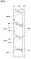
- the inboard middle land region 8B which is defined between the inboard shoulder main groove 5B and the inboard crown main groove 6B, is provided with inboard middle transverse grooves 20, inboard middle sipes 21, and dimples 22 as shown in Fig. 4 .
- the inboard middle transverse grooves 20 extend from the inboard shoulder main groove 5B to the inboard crown main groove 6B, in this example, while inclining with respect to the tire axial direction oppositely to the inclining direction of the outboard middle transverse grooves 10.
- the angle ⁇ 2 of the inboard middle transverse grooves 20 with respect to the tire axial direction is, for example, set in a range of from 30 to 40 degrees.
- Such inboard middle transverse grooves 20 can exert friction in the tire circumferential direction and tire axial direction with a good balance by their edges.
- the inboard middle transverse groove 20 includes an axially inner section 24 and an axially outer section 25.
- the axially inner section 24 is connected to the inboard crown main groove 6B.
- the axially outer section 25 is connected to the inboard shoulder main groove 5B.
- the axially outer section 25 has a groove width more than that of the axially inner section 24.
- the depth d3 of the axially inner section 24 is set in a range of from 1.0 to 2.0 mm for example.
- the axially inner section 24 is provided with a part having a constant depth. More preferably, the axially inner section 24 has a constant depth along its entire length. Such axially inner section 24 helps to prevent wear of the inboard middle land region 8B in its axial inner part.
- the maximum depth d4 of the axially outer section 25 is, for example, set in a range of from 5.5 to 6.5 mm.
- the axially outer section 25 includes a gradually decreasing part 26 whose depth is gradually decreased toward the axially inner section 24. More preferably and in this embodiment, the axially outer section 25 has an axially inner first part 27 having a constant depth, and an axially outer second part 28 having a constant depth more than that of the first part 27, and the gradually decreasing part 26 is formed therebetween.
- such axially outer section 25 leads the water in the inboard middle transverse grooves 20 toward the inboard shoulder main groove 5B.
- each inboard middle sipe 21 is disposed between the circumferentially adjacent inboard middle transverse grooves 20.
- the sipe means a narrow groove or a cut whose major part has a groove width of not more than 1.5 mm.
- the sipe may have a minor part whose width is more than 1.5 mm.
- the inboard middle sipes 21 extend axially outwardly from the inboard crown main groove 6B and terminate within the inboard middle land region 8B. Preferably, the inboard middle sipes 21 terminate axially outside the axially outer ends of the axially inner sections 24 of the inboard middle transverse grooves 20. Such inboard middle sipes 21 can be prevented the uneven wear of the inboard middle land region 8B in cooperation with the inboard middle transverse grooves 20.
- the inboard middle sipes 21 are inclined with respect to the tire axial direction to the same direction as the inboard middle transverse grooves 20.
- the inboard middle sipes 21 in this embodiment extend parallel with the inboard middle transverse grooves 20.
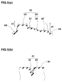
- the inboard middle sipe 21 includes a radially inner main portion 29 having a constant width, and a radially outer opening portion 30 whose width is increased from the main portion 29 to the tread 2s.
- Such inboard middle sipes 21 can improve wet performance in initial stage of the tire life.
- the dimple 22 has an opening of an elliptical shape at the tread 2s.
- the dimples 22 are formed in the vicinity of each acute angled corner 31 between the inboard shoulder main groove 5B and the inboard middle transverse groove 20 in order to improve uneven wear.
- the outboard shoulder land region 9A which is defined on the axially outside of the outboard shoulder main groove 5A, is, as shown in Fig. 6 , provided with an outboard shoulder narrow groove 33, outboard shoulder transverse grooves 34, and outboard shoulder sipes 37.
- the outboard shoulder narrow groove 33 extends continuously in the tire circumferential direction, and it is a straight groove in this embodiment.
- the groove width W6 of the outboard shoulder narrow groove 33 is, for example, set in a range of from 1.0 to 2.0 mm.
- the depth of the outboard shoulder narrow groove 33 is, for example, set in a range of from 1.0 to 4.0 mm.
- the outboard shoulder transverse grooves 34 extend axially inwardly from at least the outboard tread edge Te1. Preferably and in this embodiment, the outboard shoulder transverse grooves 34 extend axially inwardly beyond the outboard shoulder narrow groove 33.
- the angle ⁇ 3 of the outboard shoulder transverse groove 34 with respect to the tire axial direction is gradually increased toward the axially inside. During wet running, such outboard shoulder transverse groove 34 helps to lead the water in the groove toward the outside of the tire.
- the outboard shoulder transverse grooves 34 include first outboard shoulder transverse grooves 35 and second outboard shoulder transverse grooves 36.
- the first outboard shoulder transverse grooves 35 and the second outboard shoulder transverse grooves 36 are arranged alternately in the tire circumferential direction.
- first outboard shoulder transverse grooves 35 are connected to the outboard shoulder main groove 5A.
- the axially inner ends of the second outboard shoulder transverse grooves 36 are positioned axially inside the outboard shoulder narrow groove 33 within the outboard shoulder land region 9A.
- Such first outboard shoulder transverse grooves 35 and the second outboard shoulder transverse grooves 36 can provide good drainage performance while maintaining the rigidity of the outboard shoulder land region 9A.
- first outboard shoulder transverse grooves 35 are aligned with the deep groove sections 16 of the first outboard middle transverse grooves 11 as if they are smoothly continued through the outboard shoulder main groove 5A.
- the second outboard shoulder transverse grooves 36 are aligned with the second outboard middle transverse grooves 12 so that the axially inner ends of the second outboard shoulder transverse grooves 36 are positioned on lines axially outwardly extended from the second outboard middle transverse grooves 12.
- first outboard shoulder transverse grooves 35 and second outboard shoulder transverse grooves 36 lead water toward the outboard tread edge Te1 in cooperation with the outboard middle transverse grooves 10, and the wet performance can be improved.
- each outboard shoulder sipe 37 is disposed between the circumferentially adjacent outboard shoulder transverse grooves 34.
- the outboard shoulder sipes 37 extend axially inwardly from at least the outboard tread edge Te1 and terminate within the outboard shoulder land region 9A.
- the axially inner ends 37i of the outboard shoulder sipes 37 are positioned axially inside the outboard shoulder narrow groove 33.
- Such outboard shoulder sipes 37 can improve the wet performance and wandering performance with a good balance.
- the inboard shoulder land region 9B which is defined on the axially outside of the inboard shoulder main groove 5B, is, as shown in Fig. 7 , provided with an inboard shoulder narrow groove 39, inboard shoulder transverse grooves 40, and inboard shoulder sipes 41.
- the inboard shoulder narrow groove 39 is constructed similarly to the outboard shoulder narrow groove 33 and extends continuously in the tire circumferential direction.
- the inboard shoulder transverse grooves 40 extend axially inwardly from at least the inboard tread edge Te2.
- the tire axially inner ends of the inboard shoulder transverse grooves 40 are connected to the inboard shoulder main groove 5B.
- Each inboard shoulder sipe 41 is disposed between the circumferentially adjacent inboard shoulder transverse grooves 40.
- the inboard shoulder sipes 41 extend along the inboard shoulder transverse grooves 40.
- the inboard shoulder sipes 41 extend axially inwardly from at least the inboard tread edge Te2 and are connected to the inboard shoulder main groove 5B. Such inboard shoulder sipes 41 help to further improve the wet performance.
- the center land region 7 is provided with center grooves 42 each extending from one of the crown main grooves 6A and 6B and terminating within the center land region 7.
- the center grooves 42 include first center grooves 43 and second center grooves 44.
- the first center groove 43 extends axially inwardly from the outboard crown main groove 6A and terminates without reaching the tire equator C.
- the second center groove 44 extends axially inwardly from the inboard crown main groove 6B and terminates without reaching the tire equator C.
- the first center grooves 43 and the second center grooves 44 are arranged alternately in the tire circumferential direction.
- the axial length L2 of the second center grooves 44 is less than the axial length L1 of the first center grooves 43.
- Such first center grooves 43 and second center grooves 44 help to improve the wet performance while maintaining the rigidity of the center land region 7.
- each center groove 43, 44 is gradually decreased toward the tire equator C. During wet running, such center grooves 43, 44 lead water toward the crown main grooves, and the wet performance is improved.
- pneumatic tires of size 205/55R16 (rim size 16X6.5J) having specifications listed in Table 1 were experimentally manufactured and tested for the wet performance and steering stability on dry roads.
- all of the outboard middle transverse grooves were the first outboard middle transverse grooves.
- all of the outboard middle transverse grooves were the second outboard middle transverse grooves.
- test tires inflated to 220 kPa were installed on the four wheels of a test car (2000cc front wheel drive passenger car) and the following tests were carried out.
- test car was run along a 100 meter radius circle on an asphalt road partially provided with a 6 mm depth 6 m long water pool, and the lateral acceleration (lateral G) during running in the water pool was measured at the front wheels, gradually increasing the speed entering into the water pool, to obtain the average for the speed range of from 55 to 80 km/h.
- the results are indicated in Table 1 by an index based on Comparative example tire Ref.1 being 100, wherein the larger is better.
Abstract
Description
- The present invention relates to a pneumatic tire, more particularly to a tread pattern capable of improving steering stability on dry roads while maintaining wet performance.
- In Japanese Patent Application Publication No.
2013-177114 - It is therefore, an object of the present invention to provide a pneumatic tire in which the steering stability on dry roads can be improved without sacrificing the wet performance.
- According to the present invention, a pneumatic tire comprises:
- a tread portion having an outboard tread edge to be positioned away from the center of a vehicle body and an inboard tread edge to be positioned close to the center of the vehicle body, and provided with main grooves extending continuously in the tire circumferential direction,
- the main grooves including an outboard shoulder main groove and an outboard crown main groove between which an outboard middle land region is defined,
- the outboard middle land region provided with outboard middle transverse grooves each comprising a shallow groove section and a deep groove section,
- the outboard middle transverse grooves including first outboard middle transverse grooves wherein their deep groove sections are is disposed on the outboard shoulder main groove side and their shallow groove sections are disposed on the outboard crown main groove side, and
second outboard middle transverse grooves wherein their deep groove sections are disposed on the outboard crown main groove side and their shallow groove sections are disposed on the outboard shoulder main groove side, and - the first outboard middle transverse grooves and the second outboard middle transverse grooves arranged alternately in the tire circumferential direction.
- The pneumatic tire according to the present invention is provided with a tread pattern of left-right asymmetry (asymmetry about the tire equator). Accordingly, the mounting position of the tire in relation to a vehicle (which side is inside and which side is outside) is specified. Thus, the tread portion has an outboard tread edge to be positioned away from the center of the vehicle body and an inboard tread edge to be positioned close to the center of the vehicle body. For example, the sidewall portion to be located on outside when installed on the vehicle is provided with an indication such as "outside", and the sidewall portion to be located on inside is provided with an indication such as "inside".
According thereto, in this application, the terms "outboard" and "inboard" are used toward the outboard tread edge and inboard tread edge, respectively, to refer relative positions in the tire axial direction.
The terms "axially inner", "axially inward" and the like are used toward the tire equator, and
the terms "axially outer", "axially outward" and the like are used toward the adjacent tread edge in order to refer relative positions in the tire axial direction. - The tread edges are the axial outermost edges of the ground contacting patch which occurs under the normally inflated loaded condition when the camber angle of the tire is zero.
- The tread width TW is the width measured under the normally inflated unloaded condition, as the axial distance between the tread edges determined as above.
- The normally inflated unloaded condition is such that the tire is mounted on a standard wheel rim and inflate to a standard pressure but loaded with no tire load.
- The undermentioned normally inflated loaded condition is such that the tire is mounted on the standard wheel rim and inflated to the standard pressure and loaded with the standard tire load.
- The standard wheel rim is a wheel rim officially approved or recommended for the tire by standards organizations, i.e. JATMA (Japan and Asia), T&RA (North America), ETRTO (Europe), TRAA (Australia), STRO (Scandinavia), ALAPA (Latin America), ITTAC (India) and the like which are effective in the area where the tire is manufactured, sold or used. The standard pressure and the standard tire load are the maximum air pressure and the maximum tire load for the tire specified by the same organization in the Air-pressure/Maximum-load Table or similar list. For example, the standard wheel rim is the "standard rim" specified in JATMA, the "Measuring Rim" in ETRTO, the "Design Rim" in TRA or the like. The standard pressure is the "maximum air pressure" in JATMA, the "Inflation Pressure" in ETRTO, the maximum pressure given in the "Tire Load Limits at various Cold Inflation Pressures" table in TRA or the like. The standard load is the "maximum load capacity" in JATMA, the "Load Capacity" in ETRTO, the maximum value given in the above-mentioned table in TRA or the like.
- The pneumatic tire according to the present invention may have the following features (1)-(7):
- (1) each of the outboard middle transverse grooves has one end connected to the outboard shoulder main groove and the other end connected to the outboard crown main groove;
- (2) the deep groove section and the shallow groove section of each of the outboard middle transverse grooves are connected to each other in an axial center part of the outboard middle land region;
- (3) the deep groove section has a groove width more than that of the shallow groove section;
- (4) the shallow groove section has a part having a constant depth, and
the deep groove section has a part whose depth is gradually decreases toward the shallow groove section; - (5) the tread portion has an outboard shoulder land region which is defined on the axially outside of the outboard shoulder main groove and provided with outboard shoulder transverse grooves extending axially inwardly from the outboard tread edge, the outboard shoulder transverse grooves include first outboard shoulder transverse grooves whose axially inner ends are connected to the outboard shoulder main groove,
the first outboard shoulder transverse grooves are aligned with the deep groove sections of the first outboard middle transverse grooves so as to be smoothly continuous therewith through the outboard shoulder main groove; - (6) the outboard shoulder transverse grooves include second outboard shoulder transverse grooves terminating within the outboard shoulder land region, and
each of the second outboard shoulder transverse grooves is arranged between the circumferentially adjacent first outboard shoulder transverse grooves; - (7) the second outboard shoulder transverse grooves are aligned with the second outboard middle transverse groove so that the axially inner ends of the second outboard shoulder transverse grooves are substantially positioned at axially outward extensions of the second outboard middle transverse grooves.
-
-
Fig. 1 is a developed partial view of the tread portion of a pneumatic tire as an embodiment of the present invention. -
Fig. 2 is a partial top view of the outboard middle land region thereof. -
Fig. 3(a) is a cross sectional view taken along line A-A inFig. 2 showing the depth of a first outboard middle transverse groove. -
Fig. 3(b) is a cross sectional view taken along line B-BA inFig. 2 showing the depth of a second outboard middle transverse groove. -
Fig. 4 is a partial top view of the inboard middle land region of the tread portion shown inFig. 1 . -
Fig. 5(a) is a cross sectional view taken along line C-C inFig. 4 showing the depth of an inboard middle transverse groove. -
Fig. 5(b) is a cross sectional view of an inboard middle sipe taken along line D-D inFig. 4 . -
Fig. 6 is a partial top view of an outboard shoulder land region of the tread portion shown inFig. 1 . -
Fig. 7 is a partial top view of an inboard shoulder land region of the tread portion shown inFig. 1 . -
Fig. 8 is a partial top view of a center land region of the tread portion shown inFig. 1 . -
Fig. 9(a) is a cross sectional view of a first center groove taken along line E-E inFig. 8 . -
Fig. 9(b) is a cross sectional view of a second center groove taken along line F-F inFig. 8 . - The present invention can be applied to a pneumatic tire, and suitably applied to a passenger car tire.
- Taking a passenger car tire as an example, an embodiment of the present invention will now be described in detail in conjunction with the accompanying drawings.
- In the drawings, a
pneumatic tire 1 as an embodiment of the present invention comprises a tread portion, a pair of axially spaced bead portions, a pair of sidewall portions extending between the tread edges and the bead portions, a carcass extending between the bead portions, a tread reinforcing belt disposed radially outside the carcass in the tread portion as usual.
InFig. 1 , the left side is outside and the right side is inside. - The
tread portion 2 is provided withmain grooves 3 extending continuously in the tire circumferential direction to axially divide thetread portion 2 intoland regions 4. - In this embodiment, the
main grooves 3 are straight grooves.
However, themain groove 3 may be a zigzag or wavy groove. - The
main grooves 3 include
a pair of axially outermost shouldermain grooves 5 which are an outboard shouldermain groove 5A and an inboard shouldermain groove 5B, and
at least one crownmain groove 6 between the shouldermain grooves 5.
In this example, at least one crownmain groove 6 is two crownmain grooves 6 which are an outboard crownmain groove 6A on the outboard tread edge side of the tire equator C, and an inboard crownmain groove 6B on the inboard tread edge side of the tire equator C. - In this embodiment, the groove width of each
main groove 3 is preferably set in a range of about 3.0% to 8.0 % of the tread width TW, and
the groove depth of eachmain groove 3 is preferably set in a range of from 5.0 to 12.0 mm in order to provide good drainage performance. - The groove width W1 of the outboard shoulder
main groove 5A and the groove width W2 of the inboard shouldermain groove 5B are preferably less than the groove width W3 of the crownmain groove 6 in order to increase the land ratio in tread edge side portions and thereby to improve the steering stability during cornering. - Preferably, the groove width W1 of the outboard shoulder
main groove 5A is less than the groove width W2 of the inboard shouldermain groove 5B, therefore, the rubber volume of thetread portion 2 is increased on the outboard tread edge side, and thereby it is possible for the driver to feel a linear steering response even if a sharp turn is made. - The total of the groove widths of all the
main grooves 3 disposed in thetread portion 2 is preferably 24% to 32%, more preferably 26% to 30 % of the tread width TW. Thereby, the wet performance and the steering stability on dry roads can be improved with a good balance. - By the
main grooves 3, thetread portion 2 is divided into theland region 4 which are acenter land region 7, a pair of middle land region 8 (an outboardmiddle land region 8A and an inboardmiddle land region 8B), and a pair of shoulder land region 9 (an outboardshoulder land region 9A and an inboardshoulder land region 9B). - As shown in
Fig. 2 , the outboardmiddle land region 8A, which is defined between the outboard shouldermain groove 5A and the outboard crownmain groove 6A, is provided with outboard middletransverse grooves 10 extending from thegroove 5A to thegroove 6A. - The outboard middle
transverse grooves 10 are inclined at an angle θ1 of from 20 to 35 degrees with respect to the tire axial direction so as to exert friction in the tire circumferential direction and tire axial direction by their edges. - As shown in
Fig. 3(a) , the outboard middletransverse groove 10 has ashallow groove section 15 and adeep groove section 16 whose depth is more than that in the shallow groove section. Such outboard middletransverse groove 10 is helpful to improve the wet performance while maintaining the rigidity of the outboardmiddle land region 8A. - The outboard middle
transverse grooves 10 include first outboard middletransverse grooves 11 and second outboard middletransverse grooves 12 as shown inFig. 2 . - As shown in
Fig. 3(a) , in the first outboard middletransverse groove 11, thedeep groove section 16 is disposed on the outboard shouldermain groove 5A side, and theshallow groove section 15 is disposed on the outboard crownmain groove 6A side. - As shown in
Fig. 3(b) , in the second outboard middletransverse groove 12, thedeep groove section 16 is disposed on the outboard crownmain groove 6A side, and theshallow groove section 15 is disposed on the outboard shouldermain groove 5A side. - The first outboard middle
transverse grooves 11 and the second outboard middletransverse grooves 12 are arranged alternately in the tire circumferential direction. In the outboardmiddle land region 8A provided with such alternate outboard middletransverse grooves transverse grooves 12 to thereby improve the steering stability on the dry roads. The outboardmiddle land region 8A is improved in the drainage on the tire equator side by the first outboard middletransverse grooves 11 to thereby improve the wet performance. - The
shallow groove section 15 and thedeep groove section 16 of the first outboard middletransverse groove 11 and those of the second outboard middletransverse groove 12 are described hereunder. The following descriptions of theshallow groove section 15 and thedeep groove section 16 are applied to both of the first outboard middletransverse groove 11 and the second outboard middletransverse groove 12. - It is preferable that the
shallow groove section 15 and thedeep groove section 16 are connected to each other in a center region in the tire axial direction of the outboardmiddle land region 8A. Thereby, the wet performance and the steering stability on dry roads can be improved with a good balance. Here, the central portion region means a region ranging about 15 % of the width of the outboardmiddle land region 8A, toward both sides (tire equator side and tread edge side) from the center in the width direction of the outboardmiddle land region 8A. - Preferably, the groove width W5 of the
deep groove section 16 is set in a range of from 1.3 to 2.0 times the groove width W4 of theshallow groove section 15 so that thedeep groove section 16 contributes to good wet performance. - The ratio d1/d2 of the depth d1 of the
shallow groove section 15 to the depth d2 of thedeep groove section 16 is preferably not less than 0.15, more preferably not less than 0.20, but preferably not more than 0.35, more preferably not more than 0.30. Suchshallow groove section 15 anddeep groove section 16 can provide good drainage while maintaining the rigidity of the outboardmiddle land region 8A. - Preferably, the
shallow groove section 15 has a part having a constant depth.
More preferably and in this embodiment, theshallow groove section 15 has a constant depth along the entire length thereof. Suchshallow groove section 15 helps to prevent uneven wear of the outboardmiddle land region 8A while exerting the above-mentioned advantageous effect. - The maximum depth d2 of the
deep groove section 16 is preferably set in a range of from 4.5 to 7.5 mm for example. - More preferably, the
deep groove section 16 includes a gradually decreasingpart 18 whose depth is gradually decreased toward theshallow groove section 15. Thereby, from the outboardmiddle land region 8A, a part where the rigidity is suddenly changed is excluded, and the steering stability on dry roads can be improved. - Most preferably and in this embodiment, the depth of the
deep groove section 16 is gradually decreased in its entire region from the main groove to theshallow groove section 15. During wet running, suchdeep groove section 16 leads the water in the outboard middletransverse groove 10 toward the main groove, and thereby can improve the wet performance. - The inboard
middle land region 8B, which is defined between the inboard shouldermain groove 5B and the inboard crownmain groove 6B, is provided with inboard middletransverse grooves 20, inboardmiddle sipes 21, and dimples 22 as shown inFig. 4 . - The inboard middle
transverse grooves 20 extend from the inboard shouldermain groove 5B to the inboard crownmain groove 6B, in this example, while inclining with respect to the tire axial direction oppositely to the inclining direction of the outboard middletransverse grooves 10.
The angle θ2 of the inboard middletransverse grooves 20 with respect to the tire axial direction is, for example, set in a range of from 30 to 40 degrees.
Such inboard middletransverse grooves 20 can exert friction in the tire circumferential direction and tire axial direction with a good balance by their edges. - As shown in
Fig. 4 , the inboard middletransverse groove 20 includes an axiallyinner section 24 and an axiallyouter section 25. The axiallyinner section 24 is connected to the inboard crownmain groove 6B. The axiallyouter section 25 is connected to the inboard shouldermain groove 5B. The axiallyouter section 25 has a groove width more than that of the axiallyinner section 24.
The inboard middletransverse groove 20 provided with such axiallyinner section 24 and the axiallyouter section 25 helps to improve the wet performance and the steering stability on dry roads with a good balance. - As shown in
Fig. 5(a) , the depth d3 of the axiallyinner section 24 is set in a range of from 1.0 to 2.0 mm for example. Preferably, the axiallyinner section 24 is provided with a part having a constant depth.
More preferably, the axiallyinner section 24 has a constant depth along its entire length.
Such axiallyinner section 24 helps to prevent wear of the inboardmiddle land region 8B in its axial inner part. - The maximum depth d4 of the axially
outer section 25 is, for example, set in a range of from 5.5 to 6.5 mm. Preferably, the axiallyouter section 25 includes a gradually decreasingpart 26 whose depth is gradually decreased toward the axiallyinner section 24.
More preferably and in this embodiment, the axiallyouter section 25 has an axially innerfirst part 27 having a constant depth, and an axially outersecond part 28 having a constant depth more than that of thefirst part 27, and the gradually decreasingpart 26 is formed therebetween.
During wet running, such axiallyouter section 25 leads the water in the inboard middletransverse grooves 20 toward the inboard shouldermain groove 5B. - As shown in
Fig. 4 , eachinboard middle sipe 21 is disposed between the circumferentially adjacent inboard middletransverse grooves 20. - In this specification, the sipe means a narrow groove or a cut whose major part has a groove width of not more than 1.5 mm. Thus, the sipe may have a minor part whose width is more than 1.5 mm.
- The inboard
middle sipes 21 extend axially outwardly from the inboard crownmain groove 6B and terminate within the inboardmiddle land region 8B.
Preferably, the inboardmiddle sipes 21 terminate axially outside the axially outer ends of the axiallyinner sections 24 of the inboard middletransverse grooves 20.
Such inboardmiddle sipes 21 can be prevented the uneven wear of the inboardmiddle land region 8B in cooperation with the inboard middletransverse grooves 20. - In this example, the inboard
middle sipes 21 are inclined with respect to the tire axial direction to the same direction as the inboard middletransverse grooves 20. Preferably, the inboardmiddle sipes 21 in this embodiment extend parallel with the inboard middletransverse grooves 20. - As shown in
Fig. 5(b) , in the depth direction, theinboard middle sipe 21 includes a radially innermain portion 29 having a constant width, and a radiallyouter opening portion 30 whose width is increased from themain portion 29 to thetread 2s. Such inboardmiddle sipes 21 can improve wet performance in initial stage of the tire life. - As shown in
Fig. 4 , thedimple 22 has an opening of an elliptical shape at thetread 2s. - Preferably and in this embodiment, the
dimples 22 are formed in the vicinity of each acute angledcorner 31 between the inboard shouldermain groove 5B and the inboard middletransverse groove 20 in order to improve uneven wear. - The outboard
shoulder land region 9A, which is defined on the axially outside of the outboard shouldermain groove 5A, is, as shown inFig. 6 , provided with an outboard shouldernarrow groove 33, outboard shouldertransverse grooves 34, andoutboard shoulder sipes 37. - The outboard shoulder
narrow groove 33 extends continuously in the tire circumferential direction, and it is a straight groove in this embodiment.
The groove width W6 of the outboard shouldernarrow groove 33 is, for example, set in a range of from 1.0 to 2.0 mm. The depth of the outboard shouldernarrow groove 33 is, for example, set in a range of from 1.0 to 4.0 mm. - The outboard shoulder
transverse grooves 34 extend axially inwardly from at least the outboard tread edge Te1. Preferably and in this embodiment, the outboard shouldertransverse grooves 34 extend axially inwardly beyond the outboard shouldernarrow groove 33. - Preferably, the angle θ3 of the outboard shoulder
transverse groove 34 with respect to the tire axial direction is gradually increased toward the axially inside. During wet running, such outboard shouldertransverse groove 34 helps to lead the water in the groove toward the outside of the tire. - The outboard shoulder
transverse grooves 34 include first outboard shouldertransverse grooves 35 and second outboard shouldertransverse grooves 36.
The first outboard shouldertransverse grooves 35 and the second outboard shouldertransverse grooves 36 are arranged alternately in the tire circumferential direction. - The axially inner ends of the first outboard shoulder
transverse grooves 35 are connected to the outboard shouldermain groove 5A. The axially inner ends of the second outboard shouldertransverse grooves 36 are positioned axially inside the outboard shouldernarrow groove 33 within the outboardshoulder land region 9A. Such first outboard shouldertransverse grooves 35 and the second outboard shouldertransverse grooves 36 can provide good drainage performance while maintaining the rigidity of the outboardshoulder land region 9A. - More preferably, as shown in
Fig. 1 , the first outboard shouldertransverse grooves 35 are aligned with thedeep groove sections 16 of the first outboard middletransverse grooves 11 as if they are smoothly continued through the outboard shouldermain groove 5A.
Similarly, the second outboard shouldertransverse grooves 36 are aligned with the second outboard middletransverse grooves 12 so that the axially inner ends of the second outboard shouldertransverse grooves 36 are positioned on lines axially outwardly extended from the second outboard middletransverse grooves 12.
During wet running, such first outboard shouldertransverse grooves 35 and second outboard shouldertransverse grooves 36 lead water toward the outboard tread edge Te1 in cooperation with the outboard middletransverse grooves 10, and the wet performance can be improved. - As shown in
Fig. 6 , eachoutboard shoulder sipe 37 is disposed between the circumferentially adjacent outboard shouldertransverse grooves 34.
Theoutboard shoulder sipes 37 extend axially inwardly from at least the outboard tread edge Te1 and terminate within the outboardshoulder land region 9A.
Preferably and in this embodiment, the axially inner ends 37i of theoutboard shoulder sipes 37 are positioned axially inside the outboard shouldernarrow groove 33.
Suchoutboard shoulder sipes 37 can improve the wet performance and wandering performance with a good balance. - The inboard
shoulder land region 9B, which is defined on the axially outside of the inboard shouldermain groove 5B, is, as shown inFig. 7 , provided with an inboard shouldernarrow groove 39, inboard shouldertransverse grooves 40, andinboard shoulder sipes 41. - The inboard shoulder
narrow groove 39 is constructed similarly to the outboard shouldernarrow groove 33 and extends continuously in the tire circumferential direction. - The inboard shoulder
transverse grooves 40 extend axially inwardly from at least the inboard tread edge Te2. The tire axially inner ends of the inboard shouldertransverse grooves 40 are connected to the inboard shouldermain groove 5B. - Each
inboard shoulder sipe 41 is disposed between the circumferentially adjacent inboard shouldertransverse grooves 40. Theinboard shoulder sipes 41 extend along the inboard shouldertransverse grooves 40. Theinboard shoulder sipes 41 extend axially inwardly from at least the inboard tread edge Te2 and are connected to the inboard shouldermain groove 5B. Suchinboard shoulder sipes 41 help to further improve the wet performance. - The
center land region 7, which is defined between the outboard crownmain groove 6A and the inboard crownmain groove 6B, is a rib extending continuously in the tire circumferential direction as shown inFig. 8 . - The
center land region 7 is provided withcenter grooves 42 each extending from one of the crownmain grooves center land region 7. - The
center grooves 42 includefirst center grooves 43 andsecond center grooves 44.
Thefirst center groove 43 extends axially inwardly from the outboard crownmain groove 6A and terminates without reaching the tire equator C.
Thesecond center groove 44 extends axially inwardly from the inboard crownmain groove 6B and terminates without reaching the tire equator C. - The
first center grooves 43 and thesecond center grooves 44 are arranged alternately in the tire circumferential direction.
Preferably, the axial length L2 of thesecond center grooves 44 is less than the axial length L1 of thefirst center grooves 43. Suchfirst center grooves 43 andsecond center grooves 44 help to improve the wet performance while maintaining the rigidity of thecenter land region 7. - It is preferable that, as shown in
Fig. 9(a) and 9(b) , the depth of eachcenter groove
During wet running,such center grooves - While detailed description has been made of an especially preferable embodiment of the present invention, the present invention can be embodied in various forms without being limited to the illustrated embodiment
- Based on the tread pattern shown in
Fig. 1 , pneumatic tires of size 205/55R16 (rim size 16X6.5J) having specifications listed in Table 1 were experimentally manufactured and tested for the wet performance and steering stability on dry roads. In Comparative example tire Ref.1, all of the outboard middle transverse grooves were the first outboard middle transverse grooves. In Comparative example tire Ref.2, all of the outboard middle transverse grooves were the second outboard middle transverse grooves. - The test tires inflated to 220 kPa were installed on the four wheels of a test car (2000cc front wheel drive passenger car) and the following tests were carried out.
- The test car was run along a 100 meter radius circle on an asphalt road partially provided with a 6 mm depth 6 m long water pool, and the lateral acceleration (lateral G) during running in the water pool was measured at the front wheels, gradually increasing the speed entering into the water pool, to obtain the average for the speed range of from 55 to 80 km/h. The results are indicated in Table 1 by an index based on Comparative example tire Ref.1 being 100, wherein the larger is better.
- The test car was run on a dry asphalt road in a test circuit course, and the test driver evaluated the steering stability. The results are indicated by an index based on Comparative example tire Ref.1 being 100, wherein the larger the index number, the better the steering stability.
Table 1 Tire Ref.1 Ref.2 Ex.1 Ex.2 Ex.3 Ex.4 Ex.5 Ex.6 Ex.7 Ex.8 Ex.9 Ex.10 Ex.11 Ex.12 Ex.13 Ex.14 Ex.15 Ex.16 first outboard middle transverse grooves *1 PR. AB. PR. PR. PR. PR. PR. PR. PR. PR. PR. PR. PR. PR. PR. PR. PR. PR. second outboard middle transverse groove *1 AB. PR. PR. PR. PR. PR. PR. PR. PR. PR. PR. PR. PR. PR. PR. PR. PR. PR. shallow groove section's depth d1 (mm) 1.5 1.5 1.5 1.0 1.3 1.7 2.0 1.5 1.5 1.5 1.5 1.5 1.5 1.5 1.5 1.5 1.0 2.0 deep groove section's depth d2(mm) 6.1 6.1 6.1 6.1 6.1 6.1 6.1 5.0 5.5 6.5 7.0 6.1 6.1 6.1 6.1 6.1 5.0 7.0 deep groove section's width W5 / shallow groove section's width W1 1.6 1.6 1.6 1.6 1.6 1.6 1.6 1.6 1.6 1.6 1.6 1.0 1.3 2.0 2.2 1.6 1.6 1.6 gradually decreasing part *1 PR. PR. PR. PR. PR. PR. PR. PR. PR. PR. PR. PR. PR. PR. PR. AB. AB. AB. wet performance 100 100 100 99 100 102 103 98 99 100 102 99 100 101 102 100 99 103 steering stability 100 100 112 112 112 110 108 113 112 111 108 112 112 111 110 109 110 108 *1) PR.: presence, AB.: absence - From the test results, it was confirmed that the pneumatic tires according to the present invention can be improved in the steering stability on dry roads while maintaining the wet performance.
-
- 2
- tread portion
- 5A
- outboard shoulder main groove
- 5B
- inboard shoulder main groove
- 6A
- outboard crown main groove
- 6B
- inboard crown main groove
- 8A
- outboard middle land region
- 8B
- inboard middle land region
- 10
- outboard middle transverse groove
- 11
- first outboard middle transverse groove
- 12
- second outboard middle transverse groove
- 15
- shallow groove section
- 16
- deep groove section
- 20
- inboard middle transverse groove
- Te1
- outboard tread edge
- Te2
- inboard tread edge
Claims (8)
- A pneumatic tire comprising
a tread portion having an outboard tread edge to be positioned away from the center of a vehicle body and an inboard tread edge to be positioned close to the center of the vehicle body, and provided with main grooves extending continuously in the tire circumferential direction,
the main grooves including an outboard shoulder main groove and an outboard crown main groove between which an outboard middle land region is defined,
the outboard middle land region provided with outboard middle transverse grooves each comprising a shallow groove section and a deep groove section,
the outboard middle transverse grooves including first outboard middle transverse grooves wherein their deep groove sections are is disposed on the outboard shoulder main groove side and their shallow groove sections are disposed on the outboard crown main groove side, and
second outboard middle transverse grooves wherein their deep groove sections are disposed on the outboard crown main groove side and their shallow groove sections are disposed on the outboard shoulder main groove side, and
the first outboard middle transverse grooves and the second outboard middle transverse grooves arranged alternately in the tire circumferential direction. - The pneumatic tire according to claim 1, wherein
each of the outboard middle transverse grooves has one end connected to the outboard shoulder main groove and the other end connected to the outboard crown main groove. - The pneumatic tire according to claim 1 or 2, wherein
the deep groove section and the shallow groove section of each of the outboard middle transverse grooves are connected to each other in an axial center part of the outboard middle land region. - The pneumatic tire according to any one of claims 1-3, wherein the deep groove section has a groove width more than that of the shallow groove section.
- The pneumatic tire according to any one of claims 1-4, wherein the shallow groove section has a part having a constant depth, and
the deep groove section has a part whose depth is gradually decreases toward the shallow groove section. - The pneumatic tire according to any one of claims 1-5, wherein the tread portion has an outboard shoulder land region which is defined on the axially outside of the outboard shoulder main groove and provided with outboard shoulder transverse grooves extending axially inwardly from the outboard tread edge, the outboard shoulder transverse grooves include first outboard shoulder transverse grooves whose axially inner ends are connected to the outboard shoulder main groove,
the first outboard shoulder transverse grooves are aligned with the deep groove sections of the first outboard middle transverse grooves so as to be smoothly continuous therewith through the outboard shoulder main groove. - The pneumatic tire according to claim 6, wherein the outboard shoulder transverse grooves include second outboard shoulder transverse grooves terminating within the outboard shoulder land region, and
each of the second outboard shoulder transverse grooves is arranged between the circumferentially adjacent first outboard shoulder transverse grooves. - The pneumatic tire according to claim 7, wherein the second outboard shoulder transverse grooves are aligned with the second outboard middle transverse groove so that the axially inner ends of the second outboard shoulder transverse grooves are substantially positioned at axially outward extensions of the second outboard middle transverse grooves.
Applications Claiming Priority (1)
| Application Number | Priority Date | Filing Date | Title |
|---|---|---|---|
| JP2015097455A JP6434857B2 (en) | 2015-05-12 | 2015-05-12 | Pneumatic tire |
Publications (2)
| Publication Number | Publication Date |
|---|---|
| EP3093162A1 true EP3093162A1 (en) | 2016-11-16 |
| EP3093162B1 EP3093162B1 (en) | 2019-08-28 |
Family
ID=55913538
Family Applications (1)
| Application Number | Title | Priority Date | Filing Date |
|---|---|---|---|
| EP16168447.7A Active EP3093162B1 (en) | 2015-05-12 | 2016-05-04 | Pneumatic tire |
Country Status (4)
| Country | Link |
|---|---|
| US (1) | US10471776B2 (en) |
| EP (1) | EP3093162B1 (en) |
| JP (1) | JP6434857B2 (en) |
| CN (1) | CN106142997B (en) |
Cited By (6)
| Publication number | Priority date | Publication date | Assignee | Title |
|---|---|---|---|---|
| EP3248810A1 (en) * | 2016-05-25 | 2017-11-29 | Sumitomo Rubber Industries, Ltd. | Tire |
| CN108382134A (en) * | 2017-01-18 | 2018-08-10 | 住友橡胶工业株式会社 | Tire |
| CN108688410A (en) * | 2017-04-11 | 2018-10-23 | 住友橡胶工业株式会社 | Tire |
| EP3825150A1 (en) * | 2019-11-25 | 2021-05-26 | Sumitomo Rubber Industries, Ltd. | Tire |
| US11724548B2 (en) | 2019-11-25 | 2023-08-15 | Sumitomo Rubber Industries, Ltd. | Tire |
| US11878554B2 (en) | 2019-12-27 | 2024-01-23 | Sumitomo Rubber Industries, Ltd. | Tyre |
Families Citing this family (13)
| Publication number | Priority date | Publication date | Assignee | Title |
|---|---|---|---|---|
| JP2018099925A (en) * | 2016-12-19 | 2018-06-28 | 横浜ゴム株式会社 | Pneumatic tire |
| JP6828512B2 (en) * | 2017-02-28 | 2021-02-10 | 住友ゴム工業株式会社 | tire |
| JP6848641B2 (en) * | 2017-04-17 | 2021-03-24 | 住友ゴム工業株式会社 | Pneumatic tires |
| JP6885176B2 (en) * | 2017-04-18 | 2021-06-09 | 住友ゴム工業株式会社 | tire |
| JP6930241B2 (en) * | 2017-06-19 | 2021-09-01 | 横浜ゴム株式会社 | Pneumatic tires |
| CN108501622A (en) * | 2018-06-13 | 2018-09-07 | 安徽佳通乘用子午线轮胎有限公司 | A kind of UHP tires promoting wetland performance |
| JP7183848B2 (en) * | 2019-02-13 | 2022-12-06 | 住友ゴム工業株式会社 | tire |
| JP7225882B2 (en) * | 2019-02-13 | 2023-02-21 | 住友ゴム工業株式会社 | tire |
| JP7183850B2 (en) * | 2019-02-13 | 2022-12-06 | 住友ゴム工業株式会社 | tire |
| JP7183849B2 (en) * | 2019-02-13 | 2022-12-06 | 住友ゴム工業株式会社 | tire |
| JP7211218B2 (en) * | 2019-04-03 | 2023-01-24 | 住友ゴム工業株式会社 | tire |
| JP7243456B2 (en) * | 2019-05-31 | 2023-03-22 | 住友ゴム工業株式会社 | tire |
| JP7279523B2 (en) * | 2019-05-31 | 2023-05-23 | 住友ゴム工業株式会社 | tire |
Citations (4)
| Publication number | Priority date | Publication date | Assignee | Title |
|---|---|---|---|---|
| US20050183807A1 (en) * | 2004-02-23 | 2005-08-25 | Volker Hildebrand | Radial tire with improved tread pattern |
| JP2013177114A (en) | 2012-02-02 | 2013-09-09 | Yokohama Rubber Co Ltd:The | Pneumatic tire |
| WO2015037464A1 (en) * | 2013-09-11 | 2015-03-19 | 住友ゴム工業株式会社 | Pneumatic tire |
| EP2907677A2 (en) * | 2014-02-14 | 2015-08-19 | Sumitomo Rubber Industries, Ltd. | Pneumatic tire |
Family Cites Families (13)
| Publication number | Priority date | Publication date | Assignee | Title |
|---|---|---|---|---|
| FI944892A (en) * | 1993-11-18 | 1995-08-18 | Bridgestone Corp | Pneumatic tire |
| JP3583483B2 (en) * | 1993-11-18 | 2004-11-04 | 株式会社ブリヂストン | Pneumatic tire |
| JP4469399B2 (en) * | 2008-03-12 | 2010-05-26 | 住友ゴム工業株式会社 | studless tire |
| JP4685919B2 (en) * | 2008-12-08 | 2011-05-18 | 住友ゴム工業株式会社 | Pneumatic tire |
| JP5321093B2 (en) * | 2009-01-26 | 2013-10-23 | 横浜ゴム株式会社 | Pneumatic tire |
| US9481210B2 (en) * | 2010-02-26 | 2016-11-01 | Bridgestone Corporation | Pneumatic tire |
| JP5266307B2 (en) * | 2010-12-27 | 2013-08-21 | 住友ゴム工業株式会社 | Pneumatic tire |
| JP5452561B2 (en) * | 2011-09-16 | 2014-03-26 | 住友ゴム工業株式会社 | Pneumatic tire |
| EP2799254B1 (en) * | 2011-12-27 | 2017-10-11 | Bridgestone Corporation | Pneumatic tire |
| JP5385968B2 (en) * | 2011-12-28 | 2014-01-08 | 住友ゴム工業株式会社 | Pneumatic tire |
| US9346323B2 (en) | 2012-02-02 | 2016-05-24 | The Yokohama Rubber Co., Ltd. | Pneumatic tire |
| WO2015011964A1 (en) * | 2013-07-23 | 2015-01-29 | 横浜ゴム株式会社 | Pneumatic tire |
| WO2016121858A1 (en) * | 2015-01-30 | 2016-08-04 | 株式会社ブリヂストン | Pneumatic tire |
-
2015
- 2015-05-12 JP JP2015097455A patent/JP6434857B2/en active Active
-
2016
- 2016-04-14 CN CN201610230713.6A patent/CN106142997B/en active Active
- 2016-05-04 EP EP16168447.7A patent/EP3093162B1/en active Active
- 2016-05-11 US US15/151,871 patent/US10471776B2/en active Active
Patent Citations (5)
| Publication number | Priority date | Publication date | Assignee | Title |
|---|---|---|---|---|
| US20050183807A1 (en) * | 2004-02-23 | 2005-08-25 | Volker Hildebrand | Radial tire with improved tread pattern |
| JP2013177114A (en) | 2012-02-02 | 2013-09-09 | Yokohama Rubber Co Ltd:The | Pneumatic tire |
| WO2015037464A1 (en) * | 2013-09-11 | 2015-03-19 | 住友ゴム工業株式会社 | Pneumatic tire |
| EP3037282A1 (en) * | 2013-09-11 | 2016-06-29 | Sumitomo Rubber Industries, Ltd. | Pneumatic tire |
| EP2907677A2 (en) * | 2014-02-14 | 2015-08-19 | Sumitomo Rubber Industries, Ltd. | Pneumatic tire |
Cited By (8)
| Publication number | Priority date | Publication date | Assignee | Title |
|---|---|---|---|---|
| EP3248810A1 (en) * | 2016-05-25 | 2017-11-29 | Sumitomo Rubber Industries, Ltd. | Tire |
| US10668775B2 (en) | 2016-05-25 | 2020-06-02 | Sumitomo Rubber Industries, Ltd. | Tire |
| CN108382134A (en) * | 2017-01-18 | 2018-08-10 | 住友橡胶工业株式会社 | Tire |
| CN108688410A (en) * | 2017-04-11 | 2018-10-23 | 住友橡胶工业株式会社 | Tire |
| CN108688410B (en) * | 2017-04-11 | 2022-05-24 | 住友橡胶工业株式会社 | Tyre for vehicle wheels |
| EP3825150A1 (en) * | 2019-11-25 | 2021-05-26 | Sumitomo Rubber Industries, Ltd. | Tire |
| US11724548B2 (en) | 2019-11-25 | 2023-08-15 | Sumitomo Rubber Industries, Ltd. | Tire |
| US11878554B2 (en) | 2019-12-27 | 2024-01-23 | Sumitomo Rubber Industries, Ltd. | Tyre |
Also Published As
| Publication number | Publication date |
|---|---|
| CN106142997A (en) | 2016-11-23 |
| US20160332489A1 (en) | 2016-11-17 |
| JP6434857B2 (en) | 2018-12-05 |
| CN106142997B (en) | 2020-04-17 |
| EP3093162B1 (en) | 2019-08-28 |
| US10471776B2 (en) | 2019-11-12 |
| JP2016210342A (en) | 2016-12-15 |
Similar Documents
| Publication | Publication Date | Title |
|---|---|---|
| EP3093162B1 (en) | Pneumatic tire | |
| EP3296127B1 (en) | Pneumatic tire | |
| EP3147139B1 (en) | Pneumatic tire | |
| EP3213931B1 (en) | Pneumatic tire | |
| EP3095622B1 (en) | Pneumatic tire | |
| EP2789481B1 (en) | Tread band of a pneumatic tire | |
| EP3000621B1 (en) | Pneumatic tire | |
| EP3025879B1 (en) | Pneumatic tire | |
| EP2660078B1 (en) | Pneumatic tire | |
| EP2281698B1 (en) | Pneumatic tire | |
| EP3178668A1 (en) | Pneumatic tire | |
| US10486472B2 (en) | Pneumatic tire | |
| EP2923859A2 (en) | Pneumatic tire | |
| EP3456552B1 (en) | Tire | |
| EP3466726B1 (en) | Tire | |
| EP3263366A1 (en) | Tire | |
| EP3744537B1 (en) | Tire | |
| EP3456551A1 (en) | Tire | |
| EP3822093B1 (en) | Tire | |
| EP3321103B1 (en) | Heavy duty tire | |
| EP3925796A1 (en) | Tire |
Legal Events
| Date | Code | Title | Description |
|---|---|---|---|
| PUAI | Public reference made under article 153(3) epc to a published international application that has entered the european phase |
Free format text: ORIGINAL CODE: 0009012 |
|
| AK | Designated contracting states |
Kind code of ref document: A1 Designated state(s): AL AT BE BG CH CY CZ DE DK EE ES FI FR GB GR HR HU IE IS IT LI LT LU LV MC MK MT NL NO PL PT RO RS SE SI SK SM TR |
|
| AX | Request for extension of the european patent |
Extension state: BA ME |
|
| STAA | Information on the status of an ep patent application or granted ep patent |
Free format text: STATUS: REQUEST FOR EXAMINATION WAS MADE |
|
| 17P | Request for examination filed |
Effective date: 20170120 |
|
| RBV | Designated contracting states (corrected) |
Designated state(s): AL AT BE BG CH CY CZ DE DK EE ES FI FR GB GR HR HU IE IS IT LI LT LU LV MC MK MT NL NO PL PT RO RS SE SI SK SM TR |
|
| GRAP | Despatch of communication of intention to grant a patent |
Free format text: ORIGINAL CODE: EPIDOSNIGR1 |
|
| STAA | Information on the status of an ep patent application or granted ep patent |
Free format text: STATUS: GRANT OF PATENT IS INTENDED |
|
| RIC1 | Information provided on ipc code assigned before grant |
Ipc: B60C 11/03 20060101AFI20190404BHEP |
|
| INTG | Intention to grant announced |
Effective date: 20190506 |
|
| GRAS | Grant fee paid |
Free format text: ORIGINAL CODE: EPIDOSNIGR3 |
|
| GRAA | (expected) grant |
Free format text: ORIGINAL CODE: 0009210 |
|
| STAA | Information on the status of an ep patent application or granted ep patent |
Free format text: STATUS: THE PATENT HAS BEEN GRANTED |
|
| AK | Designated contracting states |
Kind code of ref document: B1 Designated state(s): AL AT BE BG CH CY CZ DE DK EE ES FI FR GB GR HR HU IE IS IT LI LT LU LV MC MK MT NL NO PL PT RO RS SE SI SK SM TR |
|
| REG | Reference to a national code |
Ref country code: GB Ref legal event code: FG4D |
|
| REG | Reference to a national code |
Ref country code: CH Ref legal event code: EP |
|
| REG | Reference to a national code |
Ref country code: AT Ref legal event code: REF Ref document number: 1171956 Country of ref document: AT Kind code of ref document: T Effective date: 20190915 |
|
| REG | Reference to a national code |
Ref country code: IE Ref legal event code: FG4D |
|
| REG | Reference to a national code |
Ref country code: DE Ref legal event code: R096 Ref document number: 602016019262 Country of ref document: DE |
|
| REG | Reference to a national code |
Ref country code: NL Ref legal event code: MP Effective date: 20190828 |
|
| REG | Reference to a national code |
Ref country code: LT Ref legal event code: MG4D |
|
| PG25 | Lapsed in a contracting state [announced via postgrant information from national office to epo] |
Ref country code: LT Free format text: LAPSE BECAUSE OF FAILURE TO SUBMIT A TRANSLATION OF THE DESCRIPTION OR TO PAY THE FEE WITHIN THE PRESCRIBED TIME-LIMIT Effective date: 20190828 Ref country code: SE Free format text: LAPSE BECAUSE OF FAILURE TO SUBMIT A TRANSLATION OF THE DESCRIPTION OR TO PAY THE FEE WITHIN THE PRESCRIBED TIME-LIMIT Effective date: 20190828 Ref country code: BG Free format text: LAPSE BECAUSE OF FAILURE TO SUBMIT A TRANSLATION OF THE DESCRIPTION OR TO PAY THE FEE WITHIN THE PRESCRIBED TIME-LIMIT Effective date: 20191128 Ref country code: NO Free format text: LAPSE BECAUSE OF FAILURE TO SUBMIT A TRANSLATION OF THE DESCRIPTION OR TO PAY THE FEE WITHIN THE PRESCRIBED TIME-LIMIT Effective date: 20191128 Ref country code: NL Free format text: LAPSE BECAUSE OF FAILURE TO SUBMIT A TRANSLATION OF THE DESCRIPTION OR TO PAY THE FEE WITHIN THE PRESCRIBED TIME-LIMIT Effective date: 20190828 Ref country code: HR Free format text: LAPSE BECAUSE OF FAILURE TO SUBMIT A TRANSLATION OF THE DESCRIPTION OR TO PAY THE FEE WITHIN THE PRESCRIBED TIME-LIMIT Effective date: 20190828 Ref country code: PT Free format text: LAPSE BECAUSE OF FAILURE TO SUBMIT A TRANSLATION OF THE DESCRIPTION OR TO PAY THE FEE WITHIN THE PRESCRIBED TIME-LIMIT Effective date: 20191230 Ref country code: FI Free format text: LAPSE BECAUSE OF FAILURE TO SUBMIT A TRANSLATION OF THE DESCRIPTION OR TO PAY THE FEE WITHIN THE PRESCRIBED TIME-LIMIT Effective date: 20190828 |
|
| PG25 | Lapsed in a contracting state [announced via postgrant information from national office to epo] |
Ref country code: LV Free format text: LAPSE BECAUSE OF FAILURE TO SUBMIT A TRANSLATION OF THE DESCRIPTION OR TO PAY THE FEE WITHIN THE PRESCRIBED TIME-LIMIT Effective date: 20190828 Ref country code: GR Free format text: LAPSE BECAUSE OF FAILURE TO SUBMIT A TRANSLATION OF THE DESCRIPTION OR TO PAY THE FEE WITHIN THE PRESCRIBED TIME-LIMIT Effective date: 20191129 Ref country code: ES Free format text: LAPSE BECAUSE OF FAILURE TO SUBMIT A TRANSLATION OF THE DESCRIPTION OR TO PAY THE FEE WITHIN THE PRESCRIBED TIME-LIMIT Effective date: 20190828 Ref country code: IS Free format text: LAPSE BECAUSE OF FAILURE TO SUBMIT A TRANSLATION OF THE DESCRIPTION OR TO PAY THE FEE WITHIN THE PRESCRIBED TIME-LIMIT Effective date: 20191228 Ref country code: RS Free format text: LAPSE BECAUSE OF FAILURE TO SUBMIT A TRANSLATION OF THE DESCRIPTION OR TO PAY THE FEE WITHIN THE PRESCRIBED TIME-LIMIT Effective date: 20190828 Ref country code: AL Free format text: LAPSE BECAUSE OF FAILURE TO SUBMIT A TRANSLATION OF THE DESCRIPTION OR TO PAY THE FEE WITHIN THE PRESCRIBED TIME-LIMIT Effective date: 20190828 |
|
| REG | Reference to a national code |
Ref country code: AT Ref legal event code: MK05 Ref document number: 1171956 Country of ref document: AT Kind code of ref document: T Effective date: 20190828 |
|
| PG25 | Lapsed in a contracting state [announced via postgrant information from national office to epo] |
Ref country code: TR Free format text: LAPSE BECAUSE OF FAILURE TO SUBMIT A TRANSLATION OF THE DESCRIPTION OR TO PAY THE FEE WITHIN THE PRESCRIBED TIME-LIMIT Effective date: 20190828 |
|
| PG25 | Lapsed in a contracting state [announced via postgrant information from national office to epo] |
Ref country code: RO Free format text: LAPSE BECAUSE OF FAILURE TO SUBMIT A TRANSLATION OF THE DESCRIPTION OR TO PAY THE FEE WITHIN THE PRESCRIBED TIME-LIMIT Effective date: 20190828 Ref country code: DK Free format text: LAPSE BECAUSE OF FAILURE TO SUBMIT A TRANSLATION OF THE DESCRIPTION OR TO PAY THE FEE WITHIN THE PRESCRIBED TIME-LIMIT Effective date: 20190828 Ref country code: IT Free format text: LAPSE BECAUSE OF FAILURE TO SUBMIT A TRANSLATION OF THE DESCRIPTION OR TO PAY THE FEE WITHIN THE PRESCRIBED TIME-LIMIT Effective date: 20190828 Ref country code: AT Free format text: LAPSE BECAUSE OF FAILURE TO SUBMIT A TRANSLATION OF THE DESCRIPTION OR TO PAY THE FEE WITHIN THE PRESCRIBED TIME-LIMIT Effective date: 20190828 Ref country code: EE Free format text: LAPSE BECAUSE OF FAILURE TO SUBMIT A TRANSLATION OF THE DESCRIPTION OR TO PAY THE FEE WITHIN THE PRESCRIBED TIME-LIMIT Effective date: 20190828 Ref country code: PL Free format text: LAPSE BECAUSE OF FAILURE TO SUBMIT A TRANSLATION OF THE DESCRIPTION OR TO PAY THE FEE WITHIN THE PRESCRIBED TIME-LIMIT Effective date: 20190828 |
|
| PG25 | Lapsed in a contracting state [announced via postgrant information from national office to epo] |
Ref country code: SK Free format text: LAPSE BECAUSE OF FAILURE TO SUBMIT A TRANSLATION OF THE DESCRIPTION OR TO PAY THE FEE WITHIN THE PRESCRIBED TIME-LIMIT Effective date: 20190828 Ref country code: IS Free format text: LAPSE BECAUSE OF FAILURE TO SUBMIT A TRANSLATION OF THE DESCRIPTION OR TO PAY THE FEE WITHIN THE PRESCRIBED TIME-LIMIT Effective date: 20200224 Ref country code: SM Free format text: LAPSE BECAUSE OF FAILURE TO SUBMIT A TRANSLATION OF THE DESCRIPTION OR TO PAY THE FEE WITHIN THE PRESCRIBED TIME-LIMIT Effective date: 20190828 Ref country code: CZ Free format text: LAPSE BECAUSE OF FAILURE TO SUBMIT A TRANSLATION OF THE DESCRIPTION OR TO PAY THE FEE WITHIN THE PRESCRIBED TIME-LIMIT Effective date: 20190828 |
|
| REG | Reference to a national code |
Ref country code: DE Ref legal event code: R097 Ref document number: 602016019262 Country of ref document: DE |
|
| PLBE | No opposition filed within time limit |
Free format text: ORIGINAL CODE: 0009261 |
|
| STAA | Information on the status of an ep patent application or granted ep patent |
Free format text: STATUS: NO OPPOSITION FILED WITHIN TIME LIMIT |
|
| PG2D | Information on lapse in contracting state deleted |
Ref country code: IS |
|
| 26N | No opposition filed |
Effective date: 20200603 |
|
| PG25 | Lapsed in a contracting state [announced via postgrant information from national office to epo] |
Ref country code: SI Free format text: LAPSE BECAUSE OF FAILURE TO SUBMIT A TRANSLATION OF THE DESCRIPTION OR TO PAY THE FEE WITHIN THE PRESCRIBED TIME-LIMIT Effective date: 20190828 |
|
| PG25 | Lapsed in a contracting state [announced via postgrant information from national office to epo] |
Ref country code: MC Free format text: LAPSE BECAUSE OF FAILURE TO SUBMIT A TRANSLATION OF THE DESCRIPTION OR TO PAY THE FEE WITHIN THE PRESCRIBED TIME-LIMIT Effective date: 20190828 Ref country code: CH Free format text: LAPSE BECAUSE OF NON-PAYMENT OF DUE FEES Effective date: 20200531 Ref country code: LI Free format text: LAPSE BECAUSE OF NON-PAYMENT OF DUE FEES Effective date: 20200531 |
|
| REG | Reference to a national code |
Ref country code: BE Ref legal event code: MM Effective date: 20200531 |
|
| GBPC | Gb: european patent ceased through non-payment of renewal fee |
Effective date: 20200504 |
|
| PG25 | Lapsed in a contracting state [announced via postgrant information from national office to epo] |
Ref country code: LU Free format text: LAPSE BECAUSE OF NON-PAYMENT OF DUE FEES Effective date: 20200504 |
|
| PG25 | Lapsed in a contracting state [announced via postgrant information from national office to epo] |
Ref country code: IE Free format text: LAPSE BECAUSE OF NON-PAYMENT OF DUE FEES Effective date: 20200504 Ref country code: GB Free format text: LAPSE BECAUSE OF NON-PAYMENT OF DUE FEES Effective date: 20200504 |
|
| PG25 | Lapsed in a contracting state [announced via postgrant information from national office to epo] |
Ref country code: BE Free format text: LAPSE BECAUSE OF NON-PAYMENT OF DUE FEES Effective date: 20200531 |
|
| PG25 | Lapsed in a contracting state [announced via postgrant information from national office to epo] |
Ref country code: MT Free format text: LAPSE BECAUSE OF FAILURE TO SUBMIT A TRANSLATION OF THE DESCRIPTION OR TO PAY THE FEE WITHIN THE PRESCRIBED TIME-LIMIT Effective date: 20190828 Ref country code: CY Free format text: LAPSE BECAUSE OF FAILURE TO SUBMIT A TRANSLATION OF THE DESCRIPTION OR TO PAY THE FEE WITHIN THE PRESCRIBED TIME-LIMIT Effective date: 20190828 |
|
| PG25 | Lapsed in a contracting state [announced via postgrant information from national office to epo] |
Ref country code: MK Free format text: LAPSE BECAUSE OF FAILURE TO SUBMIT A TRANSLATION OF THE DESCRIPTION OR TO PAY THE FEE WITHIN THE PRESCRIBED TIME-LIMIT Effective date: 20190828 |
|
| REG | Reference to a national code |
Ref country code: FR Ref legal event code: PLFP Year of fee payment: 8 |
|
| PGFP | Annual fee paid to national office [announced via postgrant information from national office to epo] |
Ref country code: FR Payment date: 20230411 Year of fee payment: 8 Ref country code: DE Payment date: 20230331 Year of fee payment: 8 |