EP3092892B1 - Emitter und tropfbewässerungsschlauch - Google Patents
Emitter und tropfbewässerungsschlauch Download PDFInfo
- Publication number
- EP3092892B1 EP3092892B1 EP15735077.8A EP15735077A EP3092892B1 EP 3092892 B1 EP3092892 B1 EP 3092892B1 EP 15735077 A EP15735077 A EP 15735077A EP 3092892 B1 EP3092892 B1 EP 3092892B1
- Authority
- EP
- European Patent Office
- Prior art keywords
- emitter
- tube
- irrigation liquid
- recess
- channel
- Prior art date
- Legal status (The legal status is an assumption and is not a legal conclusion. Google has not performed a legal analysis and makes no representation as to the accuracy of the status listed.)
- Active
Links
- 230000002262 irrigation Effects 0.000 title claims description 256
- 238000003973 irrigation Methods 0.000 title claims description 256
- 239000007788 liquid Substances 0.000 claims description 221
- 230000009467 reduction Effects 0.000 claims description 49
- 239000000463 material Substances 0.000 claims description 34
- 230000033228 biological regulation Effects 0.000 claims description 23
- 238000007599 discharging Methods 0.000 claims description 21
- 238000004891 communication Methods 0.000 claims description 2
- 230000001276 controlling effect Effects 0.000 description 25
- 230000002349 favourable effect Effects 0.000 description 19
- 229920005989 resin Polymers 0.000 description 19
- 239000011347 resin Substances 0.000 description 19
- 230000000694 effects Effects 0.000 description 11
- 238000001746 injection moulding Methods 0.000 description 10
- 238000004519 manufacturing process Methods 0.000 description 9
- -1 polyethylene Polymers 0.000 description 7
- 230000004048 modification Effects 0.000 description 6
- 238000012986 modification Methods 0.000 description 6
- 239000002689 soil Substances 0.000 description 6
- 230000002093 peripheral effect Effects 0.000 description 5
- 239000004698 Polyethylene Substances 0.000 description 4
- 230000007423 decrease Effects 0.000 description 4
- 238000000034 method Methods 0.000 description 4
- 229920000573 polyethylene Polymers 0.000 description 4
- 239000004743 Polypropylene Substances 0.000 description 3
- 239000000853 adhesive Substances 0.000 description 3
- 229920001155 polypropylene Polymers 0.000 description 3
- XLYOFNOQVPJJNP-UHFFFAOYSA-N water Substances O XLYOFNOQVPJJNP-UHFFFAOYSA-N 0.000 description 3
- 238000003466 welding Methods 0.000 description 3
- 230000008859 change Effects 0.000 description 2
- 229920001971 elastomer Polymers 0.000 description 2
- 238000003780 insertion Methods 0.000 description 2
- 230000037431 insertion Effects 0.000 description 2
- 238000005304 joining Methods 0.000 description 2
- 229920001296 polysiloxane Polymers 0.000 description 2
- 230000001105 regulatory effect Effects 0.000 description 2
- 230000000717 retained effect Effects 0.000 description 2
- 229920002379 silicone rubber Polymers 0.000 description 2
- 239000004945 silicone rubber Substances 0.000 description 2
- 230000008901 benefit Effects 0.000 description 1
- 238000004140 cleaning Methods 0.000 description 1
- 238000005094 computer simulation Methods 0.000 description 1
- 238000012258 culturing Methods 0.000 description 1
- 238000005520 cutting process Methods 0.000 description 1
- 230000000994 depressogenic effect Effects 0.000 description 1
- 238000011161 development Methods 0.000 description 1
- 239000013013 elastic material Substances 0.000 description 1
- 230000008020 evaporation Effects 0.000 description 1
- 238000001704 evaporation Methods 0.000 description 1
- 238000002474 experimental method Methods 0.000 description 1
- 239000003337 fertilizer Substances 0.000 description 1
- 239000012530 fluid Substances 0.000 description 1
- 230000006872 improvement Effects 0.000 description 1
- 230000007774 longterm Effects 0.000 description 1
- 239000012528 membrane Substances 0.000 description 1
- 239000000203 mixture Substances 0.000 description 1
- 230000037361 pathway Effects 0.000 description 1
- 230000000149 penetrating effect Effects 0.000 description 1
- 239000000243 solution Substances 0.000 description 1
- 238000012360 testing method Methods 0.000 description 1
- 238000011144 upstream manufacturing Methods 0.000 description 1
Images


Classifications
-
- A—HUMAN NECESSITIES
- A01—AGRICULTURE; FORESTRY; ANIMAL HUSBANDRY; HUNTING; TRAPPING; FISHING
- A01G—HORTICULTURE; CULTIVATION OF VEGETABLES, FLOWERS, RICE, FRUIT, VINES, HOPS OR SEAWEED; FORESTRY; WATERING
- A01G25/00—Watering gardens, fields, sports grounds or the like
- A01G25/02—Watering arrangements located above the soil which make use of perforated pipe-lines or pipe-lines with dispensing fittings, e.g. for drip irrigation
- A01G25/023—Dispensing fittings for drip irrigation, e.g. drippers
-
- A—HUMAN NECESSITIES
- A01—AGRICULTURE; FORESTRY; ANIMAL HUSBANDRY; HUNTING; TRAPPING; FISHING
- A01G—HORTICULTURE; CULTIVATION OF VEGETABLES, FLOWERS, RICE, FRUIT, VINES, HOPS OR SEAWEED; FORESTRY; WATERING
- A01G25/00—Watering gardens, fields, sports grounds or the like
- A01G25/16—Control of watering
-
- Y—GENERAL TAGGING OF NEW TECHNOLOGICAL DEVELOPMENTS; GENERAL TAGGING OF CROSS-SECTIONAL TECHNOLOGIES SPANNING OVER SEVERAL SECTIONS OF THE IPC; TECHNICAL SUBJECTS COVERED BY FORMER USPC CROSS-REFERENCE ART COLLECTIONS [XRACs] AND DIGESTS
- Y02—TECHNOLOGIES OR APPLICATIONS FOR MITIGATION OR ADAPTATION AGAINST CLIMATE CHANGE
- Y02A—TECHNOLOGIES FOR ADAPTATION TO CLIMATE CHANGE
- Y02A40/00—Adaptation technologies in agriculture, forestry, livestock or agroalimentary production
- Y02A40/10—Adaptation technologies in agriculture, forestry, livestock or agroalimentary production in agriculture
- Y02A40/22—Improving land use; Improving water use or availability; Controlling erosion
Definitions
- the present invention relates to an emitter and a trickle irrigation tube including the emitter.
- a trickle irrigation method is known as a method for culturing plants.
- a trickle irrigation tube is disposed on the soil in which plants are planted, and irrigation liquid such as water and liquid fertilizer is slowly supplied from the trickle irrigation tube to the soil.
- the trickle irrigation method can minimize the consumption amount of the irrigation liquid, and has been increasingly attracting attention in recent years.
- the trickle irrigation tube typically has a tube and an emitter (also called “dripper").
- the emitter typically supplies the soil with the irrigation liquid in the tube at a predetermined rate at which the irrigation liquid is dropped to the soil. Emitters which are pierced into the tube from the outside, and emitters joined to the inner wall surface of the tube are known.
- the latter emitter has a channel including a pressure reduction channel for allowing the irrigation liquid having entered the emitter from the internal space of the tube toward the through hole of the tube while reducing the pressure of the liquid, and a diaphragm part configured to change the volume of a portion of the channel where the irrigation liquid having reduced pressure flows in accordance with the pressure of the liquid in the tube.
- the emitter is composed of a member which is joined to the inner wall surface of the tube, a member which is disposed on the member joined to the inner wall surface, and a diaphragm part which is disposed between the two members.
- the diaphragm part is composed of an elastic film such as a silicone rubber film (see, for example, PTL 1).
- the emitter can suppress variation of the discharge rate of the irrigation liquid regardless of change of the pressure of the irrigation liquid in the tube. Therefore, the emitter is advantageous from the viewpoint of uniformly growing multiple plants.
- US 6,213,408 B1 relates to a flow regulator having an inlet, a number of flow regulating cells and an outlet.
- Each of the flow regulating cells includes a leaf-spring portion.
- the leaf-spring portion is elastically deflectable under pressure applied on its front surface by fluid flowing along a flow path from an initial unstressed state towards flexed state.
- US 4,687,143 A relates to a drip irrigation insert configured to be disposed in a sleeve.
- the drip irrigation insert has an inlet, a flow reducing pathway, a volume control region and a pair of water outlet regions.
- the volume control region includes a recess and a flexible membrane which is sealingly seated in the recess.
- US 5,246,170 A relates to a self-cleaning emitter having a body, a cap and an elastomeric diaphragm.
- the elastomeric diaphragm is provided with two intersecting slits. Each of the slits includes two faces which lie contiguous with one another and inhibit evaporation under non-use conditions. When sufficient pressure is applied to cause emission of water in an irrigation system, the elastomeric diaphragm distorts outwardly.
- the emitter is formed by assembling three components.
- the emitter may cause assembling error.
- the assembling error of the diaphragm part may cause variation of the operation of the diaphragm part, and variation of the discharge rate of the irrigation liquid.
- the emitter is typically a molded article of an inexpensive resin such as polyethylene and polypropylene, and the diaphragm part is composed of a more expensive elastic material such as a silicone rubber film.
- an inexpensive resin such as polyethylene and polypropylene
- the diaphragm part is composed of a more expensive elastic material such as a silicone rubber film.
- an emitter which can be manufactured with a single inexpensive material and fewer number of components is desired.
- An object of the present invention is to provide an emitter which can stabilize the discharge rate of the irrigation liquid and can further reduce the manufacturing cost.
- another object of the present invention is to provide a trickle irrigation tube having the emitter.
- the present invention provides an emitter as claimed in Claim 1 to be disposed on a tube for allowing irrigation liquid to flow therethrough, the emitter being configured for quantitatively discharging the irrigation liquid in the tube to outside of the tube, the emitter including: an intake part for receiving the irrigation liquid in the tube; a pressure reduction channel for allowing the irrigation liquid received from the intake part to flow therethrough while reducing a pressure of the irrigation liquid; a flow rate controlling part for controlling a flow rate of the irrigation liquid supplied from the pressure reduction channel in accordance with a pressure of the irrigation liquid supplied from the pressure reduction channel; a discharging part configured to be supplied with the irrigation liquid which is to be discharged to the outside of the tube and has a flow rate controlled by the flow rate controlling part.
- the flow rate controlling part includes a gap opening in a linear shape at a channel on a downstream side of the pressure reduction channel and communicated with the discharging part, a movable part having flexibility and including a free end facing the gap and a fixed end, the fixed end having a straight line shape and connecting both ends of the gap, and a protrusion protruding along the free end from the movable part toward the channel on the downstream side; and, when the pressure of the irrigation liquid in the channel is equal to or higher than a predetermined value, the movable part bends and the protrusion reduces a channel area of a channel of the irrigation liquid constituted by the gap.
- the protrusion has a shape like a triangular pyramid cut out from a polygonal pyramid along adjacent two sides of the polygonal pyramid which connect a tip end point and a bottom surface of the polygonal pyramid.
- One of bottom sides of the triangular pyramid which is common to a bottom side of the polygonal pyramid is the fixed end, and each of remaining two sides is the free end.
- the protrusion further includes a hollow part which opens to the discharging part side or to a side of the channel on the downstream side.
- the present invention provides a trickle irrigation tube of an embodiment of the present invention which includes: a tube; and at least one emitter disposed on the tube, the emitter being the above-mentioned emitter
- the emitter according to the present invention controls the discharge rate of the irrigation liquid in accordance with the pressure of the irrigation liquid in the trickle irrigation tube, and thus can stabilize the discharge rate of the irrigation liquid.
- the emitter according to the present invention can be formed with one or two components by injection molding of a resin material, the manufacturing cost can be further reduced in comparison with conventional emitters composed of three parts.
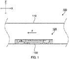
- FIG. 1 is a schematic sectional view of a trickle irrigation tube according to Embodiment 1 of the present invention.
- Trickle irrigation tube 100 is composed of tube 110 and emitter 120.
- Tube 110 is made of polyethylene, for example.
- Emitter 120 is disposed at a predetermined interval (for example, 200 to 500 mm) in the axial direction of tube 110. Each emitter 120 is joined on the inner wall surface of tube 110.
- Emitter 120 is disposed at a position where emitter 120 covers discharge port 130 of tube 110.
- Discharge port 130 is a hole which extends through the tube wall of tube 110. The hole diameter of discharge port 130 is, for example, 1.5 mm. It is to be noted that arrow F indicates the direction of flow of the irrigation liquid in tube 110.
- FIG. 2A illustrates a top surface, a front surface and a side surface of emitter 120
- FIG. 2B illustrates a bottom surface, a front surface and a side surface of emitter 120
- FIG. 3A is a plan view of emitter 120
- FIG. 3B is a rear view of emitter 120
- FIG. 3C is a side view of emitter 120
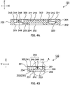
- FIG. 4A is a sectional view of emitter 120 taken along line A-A of FIG. 3A
- FIG. 4B is a sectional view of emitter 120 taken along line B-B of FIG. 3A
- FIG. 5A is a bottom view of emitter 120
- FIG. 5A is a bottom view of emitter 120
- 5B is a sectional view of emitter 120 taken along line A-A of FIG. 5A .
- the X direction is the axial direction of tube 110 or the longitudinal direction of emitter 120
- the Y direction is the short (width) direction of emitter 120
- the Z direction is the height direction of emitter 120.
- the direction of arrow F is parallel to the X direction.
- emitter 120 has a cuboid-like external shape.
- the length of emitter 120 is 30 mm in the X direction, 10 mm in the Y direction, and 3 mm in the Z direction.
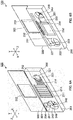
- Emitter 120 includes emitter main body 200 to be joined to the inner wall surface of tube 110, and film 300 which is formed integrally with emitter main body 200.
- FIG. 6A illustrates a top surface, a front surface and a side surface of emitter 120 in the state before film 300 is joined to emitter main body 200
- FIG. 6B illustrates a bottom surface, a front surface and a side surface of emitter 120
- FIG. 7A is a plan view of emitter 120 in the state before film 300 is joined to emitter main body 200
- FIG. 7B is a rear view of the emitter 120
- FIG. 7C is a side view of the emitter 120.
- FIG. 8A is a sectional view of emitter 120 taken along line A-A of FIG. 7A in the state before film 300 is joined to emitter main body 200
- FIG. 8A is a sectional view of emitter 120 taken along line A-A of FIG. 7A in the state before film 300 is joined to emitter main body 200
- FIG. 8A is a sectional view of emitter 120 taken along line A-A of FIG. 7A in the state before film 300 is joined to emitter main body 200
- FIG. 8B is a sectional view of the emitter 120 taken along line B-B of FIG. 7A .
- FIG. 9A is a bottom view of emitter 120 in the state before film 300 is joined to emitter main body 200
- FIG. 9B is a sectional view of the emitter 120 taken along line A-A of FIG. 9A .
- emitter main body 200 includes first surface 201 and second surface 202.
- First surface 201 is one surface which is joined to film 300 in the Z direction of emitter main body 200.
- Second surface 202 is the other surface which is joined to the inner wall surface of tube 110 in the Z direction of emitter main body 200.
- emitter main body 200 includes recesses 211 and 212 formed on first surface 201, linear protrusions 213 and 214 disposed in recesses 211 and 212, intake channel 221 extending through emitter main body 200 in the Z direction, and flow rate regulation valve 223 disposed in intake channel 221.
- recess 211 is a recess located at a center portion of first surface 201.
- the shape (hereinafter also referred to as "shape in plan view") of recess 211 as viewed from the Z direction is a rectangular shape.
- Recess 212 is a recess located at first surface 201 and configured to connect recess 211 and intake channel 221. As illustrated in FIG. 7B , the length of recess 212 in the Y direction is equal to the diameter of an opening part of intake channel 221 described later.
- linear protrusions 213 are a plurality of linear protrusions disposed in recess 211 side by side in the X direction, and the longitudinal direction of protrusions 213 is aligned in the Y direction.
- linear protrusion 213 has a rectangular shape.
- a gap is provided between linear protrusions 213 in the X direction, and between linear protrusion 213 and the wall surface of recess 211 in the Y direction.
- Linear protrusions 214 are a plurality of linear protrusions disposed side by side in the Y direction in recess 212, and the longitudinal direction of linear protrusions 214 is aligned with the X direction.
- linear protrusion 214 has a shape which is obtained by cutting out one end of a rectangular in an arc shape.
- a gap is provided between linear protrusions 214 in the Y direction, and between an end of linear protrusion 214 and linear protrusion 213 adjacent to linear protrusion 214 in the X direction.
- the distance from the bottom surface of recesses 211 and 212 to the tip end surface of linear protrusions 213 and 214 is, for example, 0.5 mm.
- the shape of the opening of intake channel 221 at first surface 201 is a circular shape as illustrated in FIG. 7A .
- Intake channel 221 has an opening diameter of, for example, 5 mm.
- the shape of the opening of intake channel 221 at second surface 202 is a shape (bell shape) which is formed with a semicircle of the above-mentioned circle and a rectangular which has a width of the diameter of the opening and extends in the Y direction from the diameter of the semicircle.
- flow rate regulation valve 223 is composed of four flexible opening-closing parts which close intake channel 221.
- the opening-closing parts have a form in which a substantially hemisphere thin dome protruding from first surface 201 side toward second surface 202 side is divided with slits in a cross shape.
- the opening-closing part has a thickness of, for example, 0.5 mm, and, normally, the slit has a width of, for example, 0 mm.
- emitter main body 200 further includes, on second surface 202, three grooves 231, 232 and 233 and hole 234 communicating between groove 233 and the first surface 201 side.
- groove 231 is connected with intake channel 221.
- Groove 231 is a linear groove formed on second surface 202 and extending along the X direction.
- groove 232 is connected with groove 231.
- Groove 232 is a groove formed on second surface 202 and extending along the X direction.
- groove 232 has a zigzag shape.
- protrusions having a substantially triangular shape protruding from the side surface of groove 232 are alternately disposed along the extending direction (the X direction) of groove 232.
- the protrusions are disposed such that the tip of each protrusion does not exceed the central line of groove 232 in plan view.
- Groove 232 has a depth of, for example, 0.5 mm, and groove 232 has a width (W in FIG. 5 ) of, for example, 0.5 mm.
- groove 233 is connected with groove 232.
- Groove 233 is a linear groove formed on second surface 202 and extending along the X direction.
- hole 234 opens at an end portion of groove 233.
- the opening shape of hole 234 is a rectangular shape.
- hole 234 opens at first surface 201.
- Grooves 231 and 233 and hole 234 have a width (the length in the Y direction) of, for example, 1 mm.
- emitter main body 200 further includes groove 241 formed on first surface 201, recess 242 formed on first surface 201, and flow rate control valve 244 disposed on the bottom of recess 242.
- groove 241 is a linear groove formed on first surface 201 and extending along the Y direction and in plan view, groove 241 has a rectangular shape. Hole 234 opens at one end of groove 241 and recess 242 is connected with the other end of groove 241.
- recess 242 is a bottomed recess formed on first surface 201.
- recess 242 has a circular shape.
- the opening diameter of recess 242 is, for example, 6 mm, and the depth of recess 242 is, for example, 2 mm.
- Recess 251 described later is located on a side opposite to recess 242 in the Z direction.
- the bottom of recess 242 has a thickness of, for example, 0.2 mm.
- flow rate control valve 244 has a configuration in which a square pyramid is divided along the sides of the square pyramid with slits in a cross shape into four right angle triangular pyramids. That is, flow rate control valve 244 includes four opening-closing parts 248 and gap 249 formed between each opening-closing parts 248.
- opening-closing part 248 has a right angle triangular pyramid-like shape whose bottom surface has a rectangular equilateral triangular shape.
- Opening-closing part 248 is composed of the bottom surface, a side surface having a right triangular-like shape, and a tilted surface having an isosceles triangular (regular triangular) shape.
- the side surface has a shape with the short side of the bottom surface having a rectangular equilateral triangular-like shape, a side orthogonal to the bottom surface, and an oblique side connecting the other two sides.
- the distance between bottom sides of opposite two opening-closing parts 248 (the distance between fixed ends of opposite two opening-closing parts 248, that is, the length of one side of the square pyramid) is, for example, 3.1 mm.
- the height of opening-closing part 248 from the bottom of recess 242 is, for example, 1.3 mm.
- the distance from the apex of opening-closing part 248 to the opening part of recess 242 in the Z direction is 0.2 mm.
- the angle of the tilted surface of opening-closing part 248 with respect to the bottom surface of recess 242 is, for example, 45°.
- gap 249 is formed in a cross shape with two linear slits orthogonal to each other. Gap 249 also opens at recess 251 described later. That is, gap 249 communicates between recess 242 and recess 251.
- the width of gap 249 in the XY plane is large at a center portion of the cross shape, and gradually decreases toward end portions thereof from the center portion.
- the length of the linear slit is, for example, 4.9 mm
- the width of the center portion of the slit (the maximum width of gap 249) is, for example, 0.3 mm.
- the angle ( ⁇ in FIG. 7A ) defined by both end edges from one end to the center portion of the slit is, for example, 5.0 to 15.0°.
- emitter main body 200 further includes linear protrusion 254 and recesses 251, 252 and 253 formed on second surface 202.
- each of recesses 251, 252 and 253 is a recess formed on second surface 202.
- recess 251 has a circular shape, and gap 249 opens at the bottom of recess 251.
- recess 252 has a rectangular shape, and linear protrusion 254 is disposed on the bottom of recess 252.
- Recess 253 is a recess which connects recess 251 and recess 252, and is shallower than the recesses. In the Y direction, recess 253 has a length smaller than the length of recess 252.
- linear protrusion 254 is a slender linear protrusion extending along the Y direction.
- linear protrusion 254 has a rectangular shape, and the length of linear protrusion 254 in the Y direction is smaller than the length of recess 252 in the Y direction and is substantially equal to the length of recess 253 in the Y direction.
- linear protrusion 254 is disposed at a position near recess 253 but is separated from recess 253.
- linear protrusion 254 is disposed at a position where linear protrusion 254 overlaps recess 253.
- film 300 is disposed integrally with emitter main body 200 through hinge part 301.
- Hinge part 301 is disposed at an edge of first surface 201 of emitter main body 200 in the Y direction.
- hinge part 301 is a portion having a thickness equal to that of film 300 and a width of 0.5 mm, and is formed integrally with emitter main body 200 and film 300.
- film 300 further includes rectangular opening part 302 at a position corresponding to first recess 211 in the state where film 300 covers first surface 201.
- the thickness of film 300 may be determined by a computer simulation or an experiment using a trial product or the like on the basis of the deformation amount under a pressure described later, and may be, for example, 0.15 mm.
- Each of emitter main body 200 and film 300 is molded with one material having flexibility such as polypropylene, for example.
- the material include resin and rubber, and examples of the resin include polyethylene and silicone.
- the flexibility of emitter main body 200 and film 300 can be adjusted with use of elastic resin materials, and for example, can be adjusted by the type of an elastic resin, the mixing ratio of an elastic resin material to a hard resin material, and the like.
- Emitter 120 can be manufactured as an integrally molded member by injection molding, for example.
- Film 300 turns about hinge part 301, and is closely joined on first surface 201 of emitter main body 200.
- the joining is performed by welding of a resin material of emitter main body 200 or film 300, by bonding using an adhesive agent, by pressure bonding of film 300 to emitter main body 200 or the like.
- intake channel 221 and recess 212 are sealed with film 300, and the gap between linear protrusions 214 opens at recess 211 and constitutes a plurality of channels connected with intake channel 221.
- intake channel 221 and the gap constitute an intake part for receiving the irrigation liquid in tube 110.
- opening-closing part 248 and gap 249 constitute a flow rate controlling part for controlling the flow rate of the irrigation liquid supplied from a pressure reduction channel described later in accordance with the flow rate of the irrigation liquid supplied from the pressure reduction channel.
- gap 249 opens in a form of two lines intersecting each other, and is connected with a discharging part described later.
- Opening-closing parts 248 are disposed with gap 249 therebetween, and are composed of right angle triangular pyramid-like parts uprightly provided in the Z direction in recess 242. That is, opening-closing part 248 includes free ends facing gap 249 and a linear fixed end connecting the both ends of gap 249, and, includes a movable part having flexibility and a protrusion protruding from the movable part along the free end toward the channel (recess 242) on the downstream side.
- Second surface 202 is joined to the inner wall surface of tube 110. This joining is performed by welding of the resin material of emitter main body 200 or tube 110, by bonding using adhesive agent, by pressure bonding of emitter main body 200 to tube 110, or the like.
- grooves 231 to 233 are sealed with tube 110.
- grooves 231 to 233 and hole 234 constitute a channel through which the irrigation liquid received from the intake part flows.
- groove 232 constitutes as a pressure reduction channel for allowing the irrigation liquid to flow therethrough while reducing the pressure of the irrigation liquid.
- recesses 251, 252 and 253 are sealed with tube 110.
- Discharge port 130 is disposed at a position where tube 110 seals recess 252.
- recess 252 constitutes as a discharge part to which the irrigation liquid having a flow rate controlled by the flow rate controlling part is supplied and which is configured to face discharge port 130.
- emitter 120 is joined to the inner periphery wall of tube 110 before discharge port 130 is formed, and thereafter, discharge port 130 is formed at a position corresponding to a discharge part (recess 252) of tube 110.
- emitter 120 may be joined to the inner wall surface of tube 110 such that emitter 120 is located at the position of preliminarily provided discharge port 130.
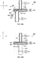
- FIG. 10A illustrates part A of FIG. 4B in an enlarged manner in the case where the pressure of the irrigation liquid in tube 110 is equal to or higher than a first pressure value and lower than a second pressure value
- FIG. 10B illustrates part A of FIG. 4B in an enlarged manner in the case where the pressure of the irrigation liquid in tube 110 is equal to or higher than the second pressure value and lower than the third pressure value
- FIG. 10C illustrates part A of FIG. 4B in an enlarged manner in the case where the pressure of the irrigation liquid in tube 110 is equal to or higher than the third pressure value.
- Supply of irrigation liquid to trickle irrigation tube 100 is performed in a range where the pressure of the irrigation liquid do not exceed 0.1 MPa in view of preventing damaging of tube 110 and emitter 120, for example.
- the irrigation liquid reaches recess 212 covered with film 300 through the gap between recess 211 and linear protrusion 213, and reaches intake channel 221 through the gap between recess 212 and linear protrusion 214.
- Recess 211 and linear protrusion 213, and recess 212 and linear protrusion 214 constitute a channel for the irrigation liquid and prevent intrusion of floating materials in the irrigation liquid larger than the gap between the linear protrusions.
- recesses 211 and 212 and linear protrusions 213 and 214 function as a filter.
- flow rate regulation valve 223 When the pressure of the irrigation liquid in tube 110 is equal to or higher than the first pressure value (for example, 0.005 MPa), flow rate regulation valve 223 is pushed to second surface 202 side, and the slit of flow rate regulation valve 223 is expanded. In this manner, the irrigation liquid reaching intake channel 221 is received into emitter main body 200 from intake channel 221. Flow rate regulation valve 223 suppresses inflow of the irrigation liquid to emitter main body 200 when the pressure value of the irrigation liquid is lower than the first pressure. Thus, high-pressure supply of the irrigation liquid to tube 110 can be achieved, and therefore the configuration in which emitter 120 has flow rate regulation valve 223 is favorable for forming trickle irrigation tube 100 having a greater length, for example.
- the first pressure value for example, 0.005 MPa
- the irrigation liquid received from intake channel 221 is supplied to groove 232 (pressure reduction channel) through groove 231.
- the pressure of the irrigation liquid flowing through groove 232 is reduced as a result of pressure loss caused by the shape (zigzag shape) in plan view of groove 232.
- floating materials in the irrigation liquid are entangled in the turbulent flow generated between the protrusions of groove 232 and are retained in groove 232. In this manner, the floating materials are further removed from the irrigation liquid by pressure reduction channel 230.
- groove 232 is favorable for allowing irrigation liquid to flow with a greater flow rate.
- the irrigation liquid having passed through groove 232 in which the pressure is reduced and the floating materials are removed is supplied to recess 242 through groove 233, hole 234, and groove 241. As illustrated in FIG. 10A , the gap between film 300 and recess 242 is filled with the irrigation liquid, and the irrigation liquid reaches recess 251 through gap 249 between opening-closing parts 248.
- the irrigation liquid having reached recess 251 reaches recess 252 through recess 253 and is then discharged out of tube 110 through discharge port 130 which faces recess 252 and opens at recess 252.
- the pressure of the irrigation liquid in tube 110 is equal to or higher than the second pressure value (for example 0.02 MPa)
- the pressure of the irrigation liquid in recess 242 increases, and opening-closing part 248 is pushed by the irrigation liquid in recess 242 as illustrated in FIG. 10B .
- the bottom side part of the tilted surface of opening-closing part 248 bends (with the bottom side part as a fixed end) and opening-closing parts 248 are brought closer to each other, thus reducing gap 249.
- the maximum width of gap 249 is changed to 0.15 mm. Consequently, the area of the channel of gap 249 for irrigation liquid and the amount of the irrigation liquid passing through gap 249 are reduced, and thus increase of the discharge rate of the irrigation liquid from discharge port 130 is suppressed.
- a third pressure value for example 0.05 MPa
- the pressure of the irrigation liquid in recess 242 further increases, and, as illustrated in FIG. 10C , opening-closing part 248 is further pushed by the irrigation liquid in recess 242, and tip end portions of opening-closing part 248 make close contact with each other while gap 249 still remain on the fixed end side between opening-closing parts 248.
- gap 249 is reduced to a minimum size.
- the irrigation liquid in recess 242 is supplied to recess 251 through gap 249 having the minimum size.
- the amount of the irrigation liquid which passes through the flow rate controlling part is restricted to a flow rate which can pass through gap 249 having the minimum size, and the discharge rate of the irrigation liquid from discharge port 130 becomes substantially constant.
- emitter 120 quantitatively discharges the irrigation liquid from tube 110 supplied with the irrigation liquid.
- opening-closing part 248 When the pressure of the irrigation liquid in tube 110 is returned to the second pressure value, opening-closing part 248 is returned to the state illustrated in FIG. 10B , and when the pressure of the irrigation liquid in tube 110 is returned to the first pressure value, opening-closing part 248 is returned to the state illustrated in FIG. 10A .
- the amount of the irrigation liquid passing through gap 249 is controlled in accordance with the pressure of the irrigation liquid of recess 242.
- the pressure of the irrigation liquid in recess 242 varies in accordance with the pressure of the irrigation liquid in tube 110.
- the discharge rate of the irrigation liquid is controlled in accordance with the pressure of the irrigation liquid in tube 110.
- emitter 120 is an emitter to be disposed on a tube 110 for allowing irrigation liquid to flow therethrough, emitter 120 being configured for quantitatively discharging the irrigation liquid in tube 110 to outside of tube 110, emitter 120 comprising: the intake part for receiving the irrigation liquid in tube 110; the pressure reduction channel for allowing the irrigation liquid received from the intake part to flow therethrough while reducing a pressure of the irrigation liquid; the flow rate controlling part for controlling a flow rate of the irrigation liquid supplied from the pressure reduction channel in accordance with a pressure of the irrigation liquid supplied from the pressure reduction channel; and, the discharging part configured to be supplied with the irrigation liquid which is to be discharged to the outside of tube 110 and has a flow rate controlled by the flow rate controlling part.
- the flow rate controlling part includes gap 249 opening in a linear shape at recess 242 which is a channel on a downstream side of the pressure reduction channel and communicated with the discharging part, a movable part having flexibility and including a free end facing gap 249 and a fixed end, the fixed end having a straight line shape and connecting both ends of gap 249, and a protrusion protruding along the free end from the movable part toward recess 242; and, when the pressure of the irrigation liquid in the channel is equal to or higher than a predetermined value, the movable part bends and the protrusion reduces a channel area of a channel of the irrigation liquid constituted by gap 249.
- emitter 120 controls the discharge rate of the irrigation liquid in accordance with the pressure of the irrigation liquid in the channel on the downstream side which varies depending on the pressure of the irrigation liquid in tube 110, and thus can stabilize the discharge rate of the irrigation liquid. Further, emitter 120 can be constituted with two injection-molded articles at most, or with one injection-molded article at least. Therefore, emitter 120 can further reduce manufacturing cost in comparison with conventional emitters composed of three parts.
- emitter 120 is an emitter for quantitatively discharging the irrigation liquid in tube 110 from discharge port 130, emitter 120 being configured to be joined to an inner wall surface of tube 110 at a position corresponding to the discharge port 130 configured to communicate between inside and outside of tube 110;
- the flow rate controlling part includes: recess 242 for constituting a part of a channel of the irrigation liquid on a downstream side of the pressure reduction channel in emitter 120, recess 242 opening at a surface of emitter 120 at a position (first surface 201) where the surface of emitter 120 is not joined to the inner wall surface; and lid part (film 300) configured to seal the opening part and block communication between the channel on the downstream side of the pressure reduction channel and the inside of tube 110;
- recess 242 has a bottom having flexibility; and gap 249 opens at the bottom of recess 242.
- This configuration is further effective from the viewpoint of constituting an emitter which can achieve the above-mentioned effects and which is to be disposed inside tube 110.
- the protrusion has a shape like a triangular pyramid cut out from a polygonal pyramid along adjacent two sides of the polygonal pyramid which connect a tip end point and a bottom surface of the polygonal pyramid, and one of bottom sides of the triangular pyramid which is common to a bottom side of the polygonal pyramid is the fixed end, and each of remaining two sides is the free end.
- This configuration makes it possible to constitute the flow rate controlling part which operates in the above-mentioned manner by injection molding with one component, and therefore the configuration is further effective from the standpoint of reducing the manufacturing cost.
- the intake part further includes flow rate regulation valve 223 for expanding the channel for the irrigation liquid when the pressure of the irrigation liquid in tube 110 is equal to or higher than a predetermined value
- the irrigation liquid can be supplied to tube 110 with a higher pressure, and therefore the configuration is favorable from the standpoint of forming trickle irrigation tube 100 having a greater length.
- emitter 120 can be produced as one component by injection molding, and therefore the configuration is further effective from the standpoint of reducing manufacturing cost.
- opening-closing part 248 is formed in a right angle triangular pyramid-like shape, the boundary between opening-closing part 248 and the bottom of recess 242 is a base end edge of opening part 248 in the tilted surface, and has a straight line shape. Consequently, since the configuration in which the boundary between opening-closing part 248 and the bottom surface of recess 242 is a straight line is favorable for performing the opening and closing of the protrusion (opening-closing part 248) with a smaller force, the configuration is further effective from the viewpoint of precisely setting a predetermined discharge rate of the irrigation liquid in emitter 120.
- trickle irrigation tube 100 including tube 110 and emitter 120 disposed to tube 110 is provided.
- Trickle irrigation tube 100 can discharge irrigation liquid at a desired discharge rate. Accordingly, trickle irrigation tube 100 is favorably used for growing plants.
- trickle irrigation tube 100 the above-described configurations may be partially changed, or other configurations may be additionally provided as long as the above-described effect is achieved.
- tube 110 may be a seamless tube, or a tube composed of slender sheet(s) joined together along the longitudinal direction.
- discharge port 130 may be a gap formed at the above-mentioned joining part of the sheets so as to communicate between the inside and the outside of tube 110, or a pipe sandwiched by the sheets at the joining part.
- the shape of the discharge port in an axial direction thereof may not be a straight line shape.
- the tube having the discharge port include a tube in which a depression having a desired shape and serving as a channel is formed on the surface of the above-mentioned sheet, and a discharge port composed of the channel is formed at the joining part when the sheets are joined together.
- intake channel 221 of emitter 120 is located at a position on the upstream side in the flow direction of the irrigation liquid in tube 110, intake channel 221 may be located at a position on the downstream side.
- orientations of a plurality of emitters 120 in one tube 110 may be identical to one another or different from one another.
- the resin material of emitter main body 200 and the resin material of film 300 may be identical to each other or different from each other.
- emitter main body 200 is integrally molded by injection molding of resin
- emitter main body 200 may be composed of two components of a first surface 201 side component and a second surface 202 side component.
- the components on the first surface 201 side are molded integrally with film 300.
- the pressure reduction channel can be disposed inside emitter main body 200, for example.
- the two components may be integrally molded through a hinge part.
- the channel connecting intake channel 221 and recess 242 which include the pressure reduction channel may be composed of a groove on first surface 201 covered with film 300 in emitter main body 200.
- second surface 202 may be a curved surface extending along the inner wall of tube 110 (for example, a surface defined by the arc whose arc radius is the internal diameter of tube 110 in the YZ plane).
- emitter 120 may not be provided with flow rate regulation valve 223.
- emitter 120 may not be provided with the pressure reduction channel.
- the pressure reduction channel may not have the above-described shape (for example, may be a simple linear channel) as long as the channel from the intake part to the flow rate regulation part is a channel which generates the above-mentioned pressure for achieving a desired operation of opening-closing part 248.
- flow rate control valve 244 may have polygonal shapes other than a square in plan view.
- flow rate control valve 244 may have a triangular shape, or a hexagonal shape in plan view.
- Flow rate control valve 244 having a plan shape with a small number of angles is favorable for facilitating the contact between opening-closing parts 248 which operate with a high pressure, and flow rate control valve 244 having a plan shape with a large number of angles is favorable for increasing the difference of the flow rate of the irrigation liquid by the operation of opening-closing part 248.
- opening-closing part 248 may not be a triangular pyramid-like member as long as opening-closing part 248 operates with the pressure of the irrigation liquid in recess 242 in the above-mentioned manner.
- opening-closing part 248 may include hollow part 255 which opens at the bottom surface of the triangular pyramid-like member (to recess 251 side), or, as illustrated in FIG. 21B , may include a hollow part 245 which opens at the tilted surface of the triangular pyramid-like member (to recess 242 side).
- opening-closing part 248 is provided with the above-mentioned hollow part is favorable for constituting opening-closing part 248 with a molded article having a constant thickness, and therefore the configuration is further effective from the viewpoint of increasing the productivity of emitter 120 by injection molding.
- one or a plurality of opening-closing parts 248 may be provided.
- opening and closing of opening-closing part 248 can be further readily designed with the configuration in which the number of movable opening-closing parts 248 is small, and the configuration in which the number of movable opening-closing part 248 is large is favorable for increasing the difference of the flow rate of the irrigation liquid by the operation of opening-closing part 248.
- the opening shape of gap 249 may be a V-shape composed of two linear slits intersecting each other.
- gap 249 may not be linear.
- the opening shape of gap 249 may be a folded shape or a curved shape which sections opening-closing part 248.
- FIG. 11 is a schematic sectional view of trickle irrigation tube 500 according to Embodiment 2 of the present invention.
- Trickle irrigation tube 500 is composed of tube 110 and emitter 320.
- the configuration of tube 110 is identical to that of the above-described Embodiment 1.
- the configuration of tube 110 is identical to that of the above-described Embodiment 1.
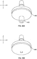
- FIG. 12A is a perspective view of emitter 320 in FIG. 1 as viewed from tube 110 side
- FIG. 12B is a perspective view of emitter 320 in FIG. 1 as viewed from a side opposite to tube 110.
- FIG. 13A is a plan view of emitter 320
- FIG. 13B is a front view of emitter 320
- FIG. 13C is a bottom view of emitter 320
- FIG. 13D is a side view of emitter 320.
- FIG. 14A is a sectional view of emitter 320 taken along line A-A of FIG. 13A
- FIG. 14B is a sectional view of emitter 320 taken along line B-B of FIG. 13A .
- Emitter 320 includes first cylindrical part 410, flange part 420 connected with first cylindrical part 410, and second cylindrical part 430 connected with flange part 420 on a side opposite to first cylindrical part 410 side.
- Flange part 420 is composed of a combination of first plate part 450 and second plate part 460.
- the Z direction is a direction along the axis of first cylindrical part 410, and includes the direction along which emitter 320 is inserted to tube 110.
- the X direction is one direction orthogonal to the Z direction
- the Y direction is a direction orthogonal to both of the Z direction and the X direction.
- first cylindrical part 410 is a cylindrical member uprightly provided on the surface of first plate part 450. As illustrated in FIG. 13A and FIG. 13B , first cylindrical part 410 is disposed at a center portion of flange part 420 in plan view.
- barb 411 is formed at a tip end portion of first cylindrical part 410.
- Barb 411 is composed of large diameter part 412 which expands from the outer peripheral surface of first cylindrical part 410 along XY plane, and tapered surface 413 whose outer diameter gradually decreases from large diameter part 412 toward the tip end of first cylindrical part 410.
- first cylindrical part 410 has an internal diameter of 2 mm
- large diameter part 412 has an outer diameter of 3.2 mm
- an end of tapered surface 413 has an outer diameter of 2.6 mm
- first cylindrical part 410 has a height from the surface of flange part 420 of 5 mm.
- flange part 420 As viewed along the Z direction (as the shape in plan view), flange part 420 has a circular shape. For example, flange part 420 has a thickness of 3 mm, and flange part 420 has an outer diameter of 16 mm.
- second cylindrical part 430 is a cylindrical member uprightly provided on the second surface of second plate part 460. As illustrated in FIG. 13B and FIG. 13C , second cylindrical part 430 is disposed at a position shifted from the center of flange part 420 in the X direction in plan view on a side opposite to first cylindrical part 410. As illustrated in FIG. 14A , second cylindrical part 430 includes an opening of recess 463 described later on the second surface. That is, second cylindrical part 430 is communicated with recess 463. The internal diameter of second cylindrical part 430 is equal to the diameter of recess 463.
- barb 431 is formed at an end portion of second cylindrical part 430 as with first cylindrical part 410.
- Barb 431 is composed of large diameter part 432 which expands from the outer peripheral surface of second cylindrical part 430 along the XY plane, and tapered surface 433 whose outer diameter gradually decreases from large diameter part 432 toward an end of second cylindrical part 430.
- second cylindrical part 430 has an internal diameter of 3 mm
- large diameter part 432 has an outer diameter of 5 mm
- the end of tapered surface 433 has an outer diameter of 4 mm
- second cylindrical part 430 has a height from the second surface of second plate part 460 of 12 mm.
- FIG. 15A is a plan view of an integrally molded article (hereinafter also referred to as "first member") of first cylindrical part 410 and first plate part 450
- FIG. 15B is a front view of the first member
- FIG. 15C is a bottom view of the first member.
- FIG. 16A is a sectional view of the first component taken along line A-A of FIG. 15A
- FIG. 16B is a sectional view of the first component taken along line B-B of FIG. 15A .
- first plate part 450 includes hole 451 opening at the surface, and recesses 453 and 454, grooves 455 and 456 and linear protrusion 457 formed on the bottom surface.
- First plate part 450 further includes flow rate regulation valve 458 which covers hole 451 at the boundary part between hole 451 and recess 453.
- hole 451 opens at a center portion of the surface of first plate part 450, and opens at recess 453 described later.
- the opening of hole 451 on the surface of first plate part 450 is included in first cylindrical part 410. That is, hole 451 communicates between first cylindrical part 410 and recess 453.
- hole 451 has a circular shape as illustrated in FIG. 13A . The diameter of hole 451 is equal to the internal diameter of first cylindrical part 410.
- recess 453 is a recess formed at a center portion of the bottom surface of first plate part 450.
- recess 453 has a circular shape as illustrated in FIG. 15C .
- the diameter of recess 453 is slightly greater than the internal diameter of first cylindrical part 410.
- Recess 453 has a depth from the bottom surface of first plate part 450 of, for example, 0.5 mm.
- groove 455 is a groove formed on the bottom surface of first plate part 450 and connected with recess 453. As illustrated in FIG. 15C , groove 455 extends along the radial direction on the bottom surface of first plate part 450 from recess 453 to a peripheral portion of the bottom surface of first plate part 450. In plan view, groove 455 has a zigzag shape similar to that of the groove 232, and groove 455 has a width (in FIG. 15C W) of, for example, 0.45 mm.
- recess 454 is a recess formed independently from recess 453 on the bottom surface of first plate part 450 at a position adjacent to recess 453 in the X direction.
- recess 454 has a rectangular shape.
- Recess 454 has a depth from the bottom surface of first plate part 450 of, for example, 0.2 mm.
- groove 456 is a groove formed on the bottom surface of first plate part 450, and connects groove 455 and recess 454.
- groove 456 has an L shape, and groove 456 is connected with groove 455 at an end of the short side of the L-shape and with recess 454 at an end portion of the long side of the L-shape.
- linear protrusion 457 is disposed at a peripheral portion of the bottom surface of first plate part 450, and as illustrated in FIG. 16 , linear protrusion 457 protrudes from the bottom surface of first plate part 450.
- linear protrusion 457 has a ring shape as illustrated in FIG. 15C .
- Linear protrusion 457 has a height from the bottom surface of first plate part 450 of, for example, 1 mm.
- flow rate regulation valve 458 is composed of four opening-closing parts.
- the opening-closing part has a form similar to the form in which a substantially hemisphere thin dome covering the opening of recess 453 side of hole 451 and protruding toward recess 453 is divided with slits in a cross shape.
- the slit has a width of, for example, 0 mm
- the opening-closing part has a thickness of, for example, 0.2 mm.
- FIG. 17A is a plan view of an integrally formed member (hereinafter also referred to as "second member") of second cylindrical part 430 and second plate part 460
- FIG. 17B is a front view of the second member
- FIG. 17C is a bottom view of the second member
- FIG. 17D is a side view of the second member.
- FIG. 18 is a sectional view of the second member taken along line A-A of FIG. 17A .
- second plate part 460 includes recess 461 and linear recess 462 formed on one surface of (first surface) and recess 463 formed on the other surface (second surface).
- Recess 461 includes flow rate control valve 464 disposed on the bottom thereof.
- recess 461 is a bottomed recess which opens at the first surface of second plate part 460.
- recess 461 has a circular shape.
- Recess 463 described later is disposed on a side opposite to recess 461 with second plate part 460 therebetween as illustrated in FIG. 18 and FIG. 17A .
- the bottom of recess 461 has a thickness of, for example, 0.2 mm.
- flow rate control valve 464 has a configuration in which a square pyramid is divided along the sides of the square pyramid with slits in a cross shape into four right angle triangular pyramids. That is, flow rate control valve 464 includes four opening-closing parts 468 and gap 469 formed between each opening-closing parts 248.
- opening-closing part 468 has a right angle triangular pyramid-like shape whose bottom surface has a rectangular equilateral triangular shape.
- opening-closing part 468 in opening-closing part 468, the oblique side of the rectangular equilateral triangle of the bottom is a fixed end, and the remaining two sides thereof orthogonal to each other are free ends.
- Opening-closing part 468 is composed of the bottom surface, a side surface having a right triangular-like shape, and a tilted surface having an isosceles triangular (regular triangular) shape.
- the side surface has a shape with the short side of the bottom surface having a rectangular equilateral triangular-like shape, a side orthogonal to the bottom surface, and an oblique side connecting the other two sides.
- the distance between bottom sides of opposite two opening-closing parts 468 (the distance between fixed ends of opposite two opening-closing parts 468, that is, the length of one side of the square pyramid) is, for example, 2.0 mm.
- the height of opening-closing part 468 from the bottom of recess 461 is, for example, 0.8 mm.
- the distance from the apex of opening-closing part 468 to the opening part of recess 461 in the Z direction is 0.2 mm.
- the angle of the tilted surface of opening-closing part 468 with respect to the bottom surface of recess 461 is, for example, 45°.
- gap 469 is formed in a cross shape with two linear slits orthogonal to each other. Gap 469 also opens at recess 463 described later. That is, gap 469 communicates between recess 463 and recess 251.
- the width of gap 469 in the XY plane is large at a center portion of the cross shape, and gradually decreases toward end portions thereof from the center portion.
- the width of the center portion of the slit (the maximum width of gap 469) is, for example, 0.3 mm.
- the angle ( ⁇ in FIG. 17C ) defined by both end edges from one end to the center portion of the slit is, for example, 5.0 to 15.0°.
- linear recess 462 is disposed at the peripheral portion of the first surface, and is depressed from the second surface as illustrated in FIG. 17B and FIG. 17D .
- linear recess 462 has a ring shape as illustrated in FIG. 17A .
- Linear recess 462 has a depth from the second surface of, for example, 1 mm.
- recess 463 is disposed at a position where recess 463 overlaps recess 461 in the Z direction in the second surface. As is obvious from FIG. 17C and FIG. 18 , recess 463 has a circular shape in plan view. Gap 469 opens at the bottom surface of recess 463.
- each of the first component and the second component is integrally molded by injection molding using one resin material having flexibility (for example, polypropylene).
- resin material having flexibility for example, polypropylene
- examples of the material of the first component and the second component include resin and rubber, and examples of the resin include polyethylene and silicone.
- the flexibility of the material is properly adjusted by the type of the resin material, mixture of two or more resin materials or the like in accordance with the flexibility required for flow rate control valve 464 (opening-closing part 468).
- first member and the second member are combined with each other by fitting linear protrusion 457 of first plate part 450 with linear recess 462 of second plate part 460, and thus emitter 320 is constituted as illustrated in FIG. 12A and FIG. 12B .
- the bottom surface of first plate part 450 and the first surface of the second plate part may be further bonded by welding of a resin material, by bonding using an adhesive agent, by pressure bonding of one of them to the other or the like.
- grooves 455 and 456 illustrated in FIG. 15C are sealed with the surface of second plate part 460, and thus the channel for irrigation liquid is constituted.
- the intake part for receiving the irrigation liquid in tube 110 is composed with first cylindrical part 410, hole 451 and recess 453.
- Groove 455 constitutes as the pressure reduction channel for allowing the irrigation liquid received from the intake part to flow therethrough while reducing the pressure of the irrigation liquid.
- recess 454 illustrated in FIG. 15C and recess 461 illustrated in FIG. 17A constitute a part of a channel on the downstream side relative to the pressure reduction channel of the irrigation liquid when the first member and the second member are combined with each other.
- opening-closing part 468 and gap 469 constitute a flow rate controlling part for controlling the flow rate of the irrigation liquid supplied from the pressure reduction channel in accordance with the pressure of the irrigation liquid supplied from the pressure reduction channel.
- the bottom of recess 461 has flexibility of the material of the second member.
- gap 469 opens in a form of two lines intersecting each other, and is connected with a discharging part described later.
- Opening-closing parts 468 are disposed with gap 469 therebetween, and are composed of right angle triangular pyramid-like parts uprightly provided in the Z direction in recess 461.
- opening-closing part 468 includes free ends facing gap 469 and a linear fixed end connecting the both ends of gap 469, and, includes a movable part having flexibility and a protrusion protruding from the movable part along the free end toward the channel (recess 461) on the downstream side.
- second cylindrical part 430 is communicated with recess 461 and constitutes as the discharge part which is supplied with irrigation liquid which is to be discharged out of tube 110 and has a flow rate controlled by the flow rate controlling part.
- emitter 320 is attached to tube 110 by inserting first cylindrical part 410 to the pipe wall of tube 110. Attaching of emitter 320 may be performed by penetrating the pipe wall of tube 110 with first cylindrical part 410, or by inserting first cylindrical part 410 to an opening part for insertion which is preliminarily formed on the pipe wall of tube 110.
- the former is favorable for arbitrarily disposing emitter 320 on tube 110, and the latter is favorable for preventing leakage of irrigation liquid from tube 110. Since first cylindrical part 410 includes a barb at an end portion thereof, dropping of emitter 320 from tube 110 is prevented.
- second cylindrical part 430 of emitter 320 includes barb 431 as illustrated in FIG. 14A and FIG. 14B . Accordingly, barb 431 can be inserted to a mulching film covering the soil, or barb 431 can be inserted to a fibrous cultivation bed. Insertion of barb 431 to the cultivation bed is favorable for specifying the position of dropping of irrigation liquid to the cultivation bed, and for fixing trickle irrigation tube 500 on the cultivation bed.
- FIG. 19A illustrates part A of FIG. 14A in an enlarged manner in the case where the pressure of the irrigation liquid in tube 110 is equal to or higher than a first pressure value and lower than a second pressure value.
- FIG. 19B illustrates part A of FIG. 14A in an enlarged manner in the case where the pressure of the irrigation liquid in tube 110 is equal to or higher than the second pressure value and lower than the third pressure value.
- FIG. 19C illustrates part A of FIG. 14A in an enlarged manner in the case where the pressure of the irrigation liquid in tube 110 is equal to or higher than the third pressure value.
- Supply of irrigation liquid to trickle irrigation tube 500 is performed in a range where the pressure of the irrigation liquid does not exceed 0.1 MPa for example in view of preventing the damaging of tube 110 and emitter 320.
- the irrigation liquid reaches flow rate regulation valve 458 through first cylindrical part 410.
- a first pressure value for example 0.005 MPa
- flow rate regulation valve 458 is pushed toward second plate part 460, and the slit of flow rate regulation valve 458 expands. In this manner, the irrigation liquid flows into flange part 420.
- Flow rate regulation valve 458 suppresses inflow of irrigation liquid into flange part 420 in the case where the pressure of the irrigation liquid is lower tm the first pressure value. The pressure of the irrigation liquid is lower tm the first pressure value.
- irrigation liquid can be supplied to the tube 110 with high pressure, and therefore the configuration in which emitter 320 includes flow rate regulation valve 458 is favorable for forming trickle irrigation tube 500 having a greater length, for example.
- the irrigation liquid having passed through flow rate regulation valve 458 is supplied to groove 455 (pressure reduction channel).
- the pressure of the irrigation liquid flowing through groove 455 is reduced as a result of pressure loss caused by the shape (zigzag shape) in plan view of groove 455.
- floating materials in the irrigation liquid are entangled in the turbulent flow generated between the protrusions of groove 455 and are retained in groove 455. In this manner, the floating materials are further removed from the irrigation liquid by groove 455.
- groove 455 is favorable for allowing irrigation liquid to flow with a greater flow rate.
- the irrigation liquid having passed through groove 455 in which the pressure is reduced and the floating materials are removed is supplied into recess 461 through groove 456.
- Recesses 454 and 461 are filled with the irrigation liquid, and the irrigation liquid passes through gap 469 ( FIG. 19A ).
- the irrigation liquid having passed through gap 469 reaches second cylindrical part 430 through recess 463, and is discharged out of tube 110 through second cylindrical part 430.
- the pressure of the irrigation liquid in tube 110 is equal to or higher than the second pressure value (for example 0.02 MPa)
- the second pressure value for example 0.02 MPa
- the pressure of the irrigation liquid in recess 461 increases, and opening-closing part 468 is pushed by the irrigation liquid in recess 461 as illustrated in FIG. 19B .
- the bottom side part of the tilted surface of opening-closing part 468 bends (with the bottom side part as a fixed end) and opening-closing parts 468 are brought closer to each other, thus reducing gap 469.
- the maximum width of gap 469 is changed to 0.15 mm. Consequently, the area of the channel of gap 469 for irrigation liquid and the amount of the irrigation liquid passing through gap 469 are reduced, and thus increase of the discharge rate of the irrigation liquid from second cylindrical part 430 is suppressed.
- a third pressure value for example 0.05 MPa
- the pressure of the irrigation liquid in recess 461 further increases, and, as illustrated in FIG. 19C , opening-closing part 468 is further pushed by the irrigation liquid in recess 461, and tip end portions of opening-closing part 468 make close contact with each other while gap 469 on the fixed ends of opening-closing parts 468 still remain.
- gap 469 is reduced to a minimum size.
- the irrigation liquid in recess 461 is supplied to recess 463 through gap 469 having the minimum size.
- emitter 320 quantitatively discharges the irrigation liquid from tube 110 supplied with the irrigation liquid.
- opening-closing part 468 When the pressure of the irrigation liquid in tube 110 is returned to the second pressure value, opening-closing part 468 is returned to the state illustrated in FIG. 19B , and when the pressure of the irrigation liquid in tube 110 is returned to the first pressure value, opening-closing part 468 is returned to the state illustrated in FIG. 19A .
- the amount of the irrigation liquid passing through gap 469 is controlled in accordance with the pressure of the irrigation liquid of recess 461.
- the pressure of the irrigation liquid in recess 461 varies in accordance with the pressure of the irrigation liquid in tube 110.
- the discharge rate of the irrigation liquid is controlled in accordance with the pressure of the irrigation liquid in tube 110.
- emitter 320 is an emitter to be disposed on a tube 110 for allowing irrigation liquid to flow therethrough, emitter 320 being configured for quantitatively discharging the irrigation liquid in tube 110 to outside of tube 110, emitter 320 comprising: the intake part for receiving the irrigation liquid in tube 110; the pressure reduction channel for allowing the irrigation liquid received from the intake part to flow therethrough while reducing a pressure of the irrigation liquid; the flow rate controlling part for controlling a flow rate of the irrigation liquid supplied from the pressure reduction channel in accordance with a pressure of the irrigation liquid supplied from the pressure reduction channel; the discharging part configured to be supplied with the irrigation liquid which is to be discharged to the outside of tube 110 and has a flow rate controlled by the flow rate controlling part.
- the flow rate controlling part includes gap 469 opening in a linear shape at recess 461 which is a channel on a downstream side of the pressure reduction channel and connected with the discharging part, a movable part having flexibility and including a free end facing gap 469 and a fixed end, the fixed end having a straight line shape and connecting both ends of gap 469, and a protrusion protruding along the free end from the movable part toward recess 461; and, when the pressure of the irrigation liquid in the channel is equal to or higher than a predetermined value, the movable part bends and the protrusion reduces a channel area of a channel of the irrigation liquid constituted by gap 469.
- emitter 320 controls the discharge rate of the irrigation liquid in accordance with the pressure of the irrigation liquid in the channel on the downstream side which varies depending on the pressure of the irrigation liquid in tube 110, and thus can stabilize the discharge rate of the irrigation liquid. Further, emitter 320 can be constituted with two injection-molded articles. Therefore, emitter 320 can further reduce manufacturing cost in comparison with conventional emitters composed of three parts.
- emitter 320 includes: first cylindrical part 410 for constituting the intake part; flange part 420 for forming the pressure reduction channel and the flow rate controlling part, flange part 420 being connected with one end of first cylindrical part 410 and extending outward from the one end of first cylindrical part 410; and second cylindrical part 430 for constituting the discharge part, second cylindrical part 430 being connected on a side opposite to first cylindrical part 410 of flange part 420; emitter 320 is disposed on tube 110 by inserting first cylindrical part 410 into tube 110 from outside of tube 110; flange part 420 is composed of a combination of first plate part 450 connected with first cylindrical part 410 and second plate part 460 connected with second cylindrical part 430; first plate part 450 includes the pressure reduction channel; second plate part 460 includes recess 461 opening at a channel on a downstream side of the pressure reduction channel; recess 461 has a bottom having flexibility; and gap 469 opens at the bottom of recess 461.
- This configuration is further effective from the viewpoint of constituting emit
- the protrusion has a shape like a triangular pyramid cut out from a polygonal pyramid along adjacent two sides of the polygonal pyramid which connect a tip end point and a bottom surface of the polygonal pyramid, and one of bottom sides of the triangular pyramid which is common to a bottom side of the polygonal pyramid is the fixed end, and each of remaining two sides is the free end.
- This configuration makes it possible to constitute the flow rate controlling part which operates in the above-mentioned manner by injection molding with one component, and is further effective from the viewpoint of reducing manufacturing cost.
- the intake part further includes flow rate regulation valve 458 for expanding the channel for the irrigation liquid when the pressure of the irrigation liquid in tube 110 is equal to or higher than a predetermined value
- the irrigation liquid can be supplied to tube 110 with a higher pressure, and therefore the configuration is favorable from the standpoint of forming trickle irrigation tube 500 having a greater length.
- emitter 320 can be produced as one component by injection molding, and therefore the configuration is further effective from the standpoint of reducing manufacturing cost.
- opening-closing part 468 is formed in a right angle triangular pyramid-like shape, the boundary between opening-closing part 468 and the bottom of recess 461 is a base end edge of opening part 468 in the tilted surface, and has a straight line shape. Consequently, since the configuration in which the boundary between opening-closing part 468 and the bottom surface of recess 461 is a straight line is favorable for performing the opening and closing of the protrusion (opening-closing part 468) with a smaller force, the configuration is further effective from the viewpoint of precisely setting a predetermined discharge rate of the irrigation liquid in emitter 320.
- trickle irrigation tube 500 including tube 110 and emitter 320 disposed to tube 110 is provided.
- Trickle irrigation tube 500 can discharge irrigation liquid at a desired discharge rate. Accordingly, trickle irrigation tube 500 is favorably used for growing plants.
- trickle irrigation tube 500 the above-described configurations may be partially changed, or other configurations may be additionally provided as long as the above-described effect is achieved.
- second cylindrical part 430 may not have barb 431 as illustrated in FIG. 20A , and may be an opening part which opens at the second surface of second plate part 460 as illustrated in FIG. 20B .
- tube 110 may be a seamless tube, a tube composed of slender sheet(s) joined together along the longitudinal direction, or a tube having a gap formed at the above-mentioned joining part of the sheets so as to communicate between the inside and the outside of tube 110, or a pipe sandwiched by the sheets at the joining part.
- first component and the second component may be integrally formed so as to be turnable about a hinge part integrally formed with the first component and the second component.
- the number of components of emitter 320 can be further reduced, that is, emitter 320 can be produced with one component.
- emitter 320 may not be provided with the pressure reduction channel.
- the pressure reduction channel may not have the above-described shape (for example, may be a simple linear channel) as long as the channel from the intake part to the flow rate regulation part is a channel which generates the above-mentioned pressure for achieving a desired operation of opening-closing part 468.
- flow rate control valve 464 may have polygonal shapes other than a square in plan view.
- flow rate control valve 464 may have a triangular shape, or a hexagonal shape in plan view.
- Flow rate control valve 464 having a plan shape with a small number of angles is favorable for facilitating the contact between opening-closing parts 468 which operate with a high pressure, and flow rate control valve 464 having a plan shape with a large number of angles is favorable for increasing the difference of the flow rate of the irrigation liquid by the operation of opening-closing part 468.
- opening-closing part 468 may include a hollow part illustrated in FIG. 21A and FIG. 21B .
- the configuration in which opening-closing part 468 is provided with the above-mentioned hollow part is favorable for constituting opening-closing part 468 with a molded article having a constant thickness, and therefore the configuration is further effective from the viewpoint of increasing the productivity of emitter 320 by injection molding.
- one or a plurality of opening-closing parts 468 may be provided.
- opening and closing of opening-closing part 468 can be further readily designed with the configuration in which the number of movable opening-closing parts 468 is small, and the configuration in which the number of movable opening-closing part 468 is large is favorable for increasing the difference of the flow rate of the irrigation liquid by the operation of opening-closing part 468.
- the opening shape of gap 469 may be a V-shape composed of two linear slits intersecting each other.
- gap 469 may not be linear.
- the opening shape of gap 469 may be a folded shape or a curved shape which sections opening-closing part 468.
- an emitter which can discharge liquid with an appropriate speed by the pressure of the liquid to be discharged can be easily provided. Accordingly, popularization of the above-mentioned emitter in technical fields of trickle irrigations, endurance tests and the like where long-term discharging is required, and further development of the technical fields can be expected.
Landscapes
- Life Sciences & Earth Sciences (AREA)
- Engineering & Computer Science (AREA)
- Water Supply & Treatment (AREA)
- Environmental Sciences (AREA)
- Soil Sciences (AREA)
- Nozzles (AREA)
- Infusion, Injection, And Reservoir Apparatuses (AREA)
Claims (6)
- Emitter (120, 320) zum Anordnen auf einem Schlauch (110), um zu ermöglichen, dass eine Bewässerungsflüssigkeit dort hindurch fließt, wobei der Emitter (120, 320) dazu eingerichtet ist, die Bewässerungsflüssigkeit in dem Schlauch (110) mengenmäßig an eine Außenseite des Schlauchs (110) abzugeben, wobei der Emitter (120, 320) umfasst:ein Einlaufteil zum Aufnehmen der Bewässerungsflüssigkeit in dem Schlauch (110);einen Druckverminderungskanal, um zu ermöglichen, dass die vom Einlaufteil aufgenommene Bewässerungsflüssigkeit durch ihn hindurchfließt, während er einen Druck der Bewässerungsflüssigkeit vermindert;ein Durchflussmengensteuerteil zum Steuern einer Durchflussmenge der vom Druckverminderungskanal zugeführten Bewässerungsflüssigkeit in Übereinstimmung mit einem Druck der Bewässerungsflüssigkeit, die von dem Druckverminderungskanal zugeführt wird;ein Auslassteil, das dazu eingerichtet ist, mit der Bewässerungsflüssigkeit gespeist zu werden, die an die Außenseite des Schlauchs (110) abgegeben werden soll und eine Durchflussmenge aufweist, die von dem Durchflussmengensteuerteil gesteuert wird, wobei:das Durchflussmengensteuerteil umfasst:einen Spalt (249, 469), der sich linienförmig bei einem Kanal auf einer stromabwärts gelegenen Seite des Druckverminderungskanals öffnet und mit dem Auslassteil verbunden ist,einen beweglichen Teil, der Flexibilität aufweist und ein dem Spalt (249, 469) gegenüberliegendes freies Ende und ein festes Ende umfasst, wobei das feste Ende eine geradlinige Form hat und beide Enden des Spalts (249, 469) verbindet, undeinen Vorsprung (248, 468), der entlang dem freien Ende von dem beweglichen Teil zu dem Kanal auf der stromabwärts gelegenen Seite des Druckverminderungskanals vorsteht;der Vorsprung (248, 468) eine Form wie eine dreieckige Pyramide aufweist, die aus einer vieleckigen Pyramide entlang zwei angrenzenden Seiten der vieleckigen Pyramide ausgeschnitten ist, die einen Spitzenendpunkt und eine Grundfläche der vieleckigen Pyramide verbinden; undeine von Grundseiten der dreieckigen Pyramide, die einer Grundseite der vieleckigen Pyramide gemeinsam ist, das feste Ende ist und jede der übrigen zwei Seiten das freie Ende ist; undwenn der Druck der Bewässerungsflüssigkeit in dem Kanal gleich oder höher als ein vorgegebener Wert ist, sich der bewegliche Teil biegt und der Vorsprung (248, 468) eine Kanalfläche eines Kanals der Bewässerungsflüssigkeit verringert, der von dem Spalt (249, 469) gebildet wird,dadurch gekennzeichnet, dassder Vorsprung (248, 468) ferner einen hohlen Teil (245, 255) umfasst, der sich zur Auslassteilseite oder zu einer Seite des Kanal auf der stromabwärts gelegenen Seite hin öffnet.
- Emitter (120, 320) nach Anspruch 1, wobei das Einlaufteil ferner ein Durchflussmengenregelventil (223, 458) umfasst, das dazu eingerichtet ist, den Kanal der Bewässerungsflüssigkeit aufzuweiten, wenn der Druck der Bewässerungsflüssigkeit in dem Schlauch (110) gleich oder höher als ein vorgegebener Wert ist.
- Emitter (120) nach Anspruch 1 oder 2, wobei:der Emitter (120) ein Emitter für die mengenmäßige Abgabe der Bewässerungsflüssigkeit in dem Schlauch (110) aus einer Auslassöffnung (130) ist, wobei der Emitter (120) dazu eingerichtet ist, mit einer Innenwandfläche des Schlauchs (110) in einer Position verbunden zu sein, die der Auslassöffnung (130) entspricht, die dazu eingerichtet ist, zwischen der Innenseite und der Außenseite des Schlauchs (110) eine Verbindung herzustellen;das Durchflussmengensteuerteil umfasst:eine Vertiefung (242) zum Bilden eines Teils eines Kanals der Bewässerungsflüssigkeit auf einer stromabwärts gelegenen Seite des Druckverminderungskanals in dem Emitter (120), wobei die Vertiefung (242) an einer Oberfläche des Emitters (120) in einer Position offen ist, in der die Oberfläche des Emitters (120) nicht mit der Innenwandfläche verbunden ist, undeinen Deckelteil (300), der dazu eingerichtet ist, das Öffnungsteil zu verschließen und die Verbindung zwischen dem Kanal auf der stromabwärts gelegenen Seite des Druckverminderungskanals und der Innenseite des Schlauchs (110) zu unterbrechen;die Vertiefung (242) einen Boden hat, der Flexibilität aufweist; undsich der Spalt (249) am Boden der Vertiefung (242) öffnet.
- Emitter (320) nach Anspruch 1 oder 2, wobei:der Emitter (320) umfasst:einen ersten zylindrischen Teil (410) zum Bilden des Einlaufteils;einen Flanschteil (420) zum Ausbilden des Druckverminderungskanals und des Durchflussmengensteuerteils, wobei der Flanschteil (420) mit einem Ende des ersten zylindrischen Teils (410) verbunden ist und sich nach außen von dem einen Ende des ersten zylindrischen Teils (410) erstreckt; undeinen zweiten zylindrischen Teil (430) zum Bilden des Auslassteils, wobei der zweite zylindrische Teil (430) auf einer dem ersten zylindrischen Teil (410) entgegengesetzten Seite des Flanschteils (420) angeschlossen ist;der Emitter (320) dazu eingerichtet ist, auf dem Schlauch (110) durch Einsetzen des ersten zylindrischen Teils (410) in den Schlauch (110) von außerhalb des Schlauchs (110) angeordnet zu werden;der Flanschteil (420) aus einer Kombination aus einem ersten Plattenteil (450), der mit dem ersten zylindrischen Teil (410) verbunden ist, und einem zweiten Plattenteil (460) zusammengesetzt ist, der mit dem zweiten zylindrischen Teil (430) verbunden ist;der erste Plattenteil (450) den Druckverminderungskanal umfasst;der zweite Plattenteil (460) eine Vertiefung (461) umfasst, die an einem Kanal auf einer stromabwärts gelegenen Seite des Druckverminderungskanals offen ist;die Vertiefung (461) einen Boden hat, der Flexibilität aufweist; undsich der Spalt (469) am Boden der Vertiefung (461) öffnet.
- Emitter (120, 320) nach einem der Ansprüche 3 bis 4, wobei der Emitter (120, 320) mit einem Material geformt ist, das Flexibilität aufweist.
- Tröpfchenbewässerungsschlauch (100, 500), umfassend:einen Schlauch (110); undmindestens einen Emitter, wobei der Emitter der auf dem Schlauch (110) angeordnete Emitter (120, 320) nach einem der Ansprüche 1 bis 5 ist.
Applications Claiming Priority (2)
| Application Number | Priority Date | Filing Date | Title |
|---|---|---|---|
| JP2014003264 | 2014-01-10 | ||
| PCT/JP2015/050082 WO2015105082A1 (ja) | 2014-01-10 | 2015-01-06 | エミッタおよび点滴灌漑用チューブ |
Publications (3)
| Publication Number | Publication Date |
|---|---|
| EP3092892A1 EP3092892A1 (de) | 2016-11-16 |
| EP3092892A4 EP3092892A4 (de) | 2017-08-30 |
| EP3092892B1 true EP3092892B1 (de) | 2020-06-17 |
Family
ID=53523907
Family Applications (1)
| Application Number | Title | Priority Date | Filing Date |
|---|---|---|---|
| EP15735077.8A Active EP3092892B1 (de) | 2014-01-10 | 2015-01-06 | Emitter und tropfbewässerungsschlauch |
Country Status (7)
| Country | Link |
|---|---|
| US (1) | US10383290B2 (de) |
| EP (1) | EP3092892B1 (de) |
| JP (1) | JP6577367B2 (de) |
| CN (1) | CN105916370B (de) |
| ES (1) | ES2804709T3 (de) |
| IL (1) | IL246662A0 (de) |
| WO (1) | WO2015105082A1 (de) |
Families Citing this family (28)
| Publication number | Priority date | Publication date | Assignee | Title |
|---|---|---|---|---|
| US7648085B2 (en) | 2006-02-22 | 2010-01-19 | Rain Bird Corporation | Drip emitter |
| US9485923B2 (en) | 2012-03-26 | 2016-11-08 | Rain Bird Corporation | Elastomeric emitter and methods relating to same |
| US9877440B2 (en) | 2012-03-26 | 2018-01-30 | Rain Bird Corporation | Elastomeric emitter and methods relating to same |
| US10440903B2 (en) | 2012-03-26 | 2019-10-15 | Rain Bird Corporation | Drip line emitter and methods relating to same |
| US20130248622A1 (en) | 2012-03-26 | 2013-09-26 | Jae Yung Kim | Drip line and emitter and methods relating to same |
| US9872444B2 (en) | 2013-03-15 | 2018-01-23 | Rain Bird Corporation | Drip emitter |
| US10285342B2 (en) | 2013-08-12 | 2019-05-14 | Rain Bird Corporation | Elastomeric emitter and methods relating to same |
| USD811179S1 (en) | 2013-08-12 | 2018-02-27 | Rain Bird Corporation | Emitter part |
| US10631473B2 (en) | 2013-08-12 | 2020-04-28 | Rain Bird Corporation | Elastomeric emitter and methods relating to same |
| US9883640B2 (en) | 2013-10-22 | 2018-02-06 | Rain Bird Corporation | Methods and apparatus for transporting elastomeric emitters and/or manufacturing drip lines |
| EP3075235B1 (de) * | 2013-11-27 | 2019-07-31 | Enplas Corporation | Emitter und tropfbewässerungsschlauch |
| CN105792637B (zh) * | 2013-11-27 | 2019-12-27 | 恩普乐股份有限公司 | 发射器和滴灌用输送管 |
| WO2015080127A1 (ja) * | 2013-11-27 | 2015-06-04 | 株式会社エンプラス | エミッタおよび点滴灌漑用チューブ |
| WO2015098412A1 (ja) * | 2013-12-27 | 2015-07-02 | 株式会社エンプラス | エミッタおよび点滴灌漑用チューブ |
| US10330559B2 (en) | 2014-09-11 | 2019-06-25 | Rain Bird Corporation | Methods and apparatus for checking emitter bonds in an irrigation drip line |
| JP6689634B2 (ja) * | 2016-03-17 | 2020-04-28 | 株式会社エンプラス | エミッタおよび点滴灌漑用チューブ |
| US10375904B2 (en) | 2016-07-18 | 2019-08-13 | Rain Bird Corporation | Emitter locating system and related methods |
| JP6710602B2 (ja) * | 2016-08-01 | 2020-06-17 | 株式会社エンプラス | エミッタおよび点滴灌漑用チューブ |
| WO2018140772A1 (en) | 2017-01-27 | 2018-08-02 | Rain Bird Corporation | Pressure compensation members, emitters, drip line and methods relating to same |
| JP6837377B2 (ja) * | 2017-04-12 | 2021-03-03 | 株式会社エンプラス | エミッタおよび点滴灌漑用チューブ |
| JP6831741B2 (ja) * | 2017-04-12 | 2021-02-17 | 株式会社エンプラス | エミッタおよび点滴灌漑用チューブ |
| US10626998B2 (en) * | 2017-05-15 | 2020-04-21 | Rain Bird Corporation | Drip emitter with check valve |
| JP2018201426A (ja) * | 2017-06-06 | 2018-12-27 | 株式会社エンプラス | エミッタおよびそれを有する点滴灌漑用チューブ |
| JP2019058099A (ja) * | 2017-09-26 | 2019-04-18 | 株式会社エンプラス | エミッタおよび点滴灌漑用チューブ |
| USD883048S1 (en) | 2017-12-12 | 2020-05-05 | Rain Bird Corporation | Emitter part |
| WO2019146528A1 (ja) * | 2018-01-23 | 2019-08-01 | 株式会社エンプラス | エミッタおよび点滴灌漑用チューブ |
| JP7101045B2 (ja) * | 2018-05-28 | 2022-07-14 | 株式会社エンプラス | エミッタおよび点滴灌漑用チューブ |
| US11985924B2 (en) | 2018-06-11 | 2024-05-21 | Rain Bird Corporation | Emitter outlet, emitter, drip line and methods relating to same |
Family Cites Families (18)
| Publication number | Priority date | Publication date | Assignee | Title |
|---|---|---|---|---|
| US4161291A (en) | 1978-11-01 | 1979-07-17 | Clarence Bentley | Emitter |
| IL76553A (en) * | 1985-10-03 | 1993-01-31 | Naan Mech Works | Drip irrigation apparatus |
| IL93255A (en) * | 1990-02-02 | 1997-03-18 | Plastro Gvat | Drip irrigation lines |
| US5246170A (en) | 1991-03-08 | 1993-09-21 | Woidt Rienhold W | Self cleaning emitter |
| IL100749A (en) | 1992-01-24 | 1996-01-31 | Plastro Gvat | Regulated drip irrigation emitter with improved membrane |
| IL121967A (en) | 1997-10-14 | 2001-06-14 | Hydro Plan Eng Ltd | Irrigation output unit |
| IL122777A (en) * | 1997-12-28 | 2003-12-10 | Amir Cohen | Valve controlled drip irrigation lines |
| US6213408B1 (en) | 1999-11-18 | 2001-04-10 | Eureka Technologies Ltd | Flow regulator and corresponding method with pressure responsive flow regulation |
| AU2002303144A1 (en) * | 2001-03-16 | 2002-10-03 | The Toro Company | Drip irrigation emitter |
| US7175113B2 (en) * | 2001-11-26 | 2007-02-13 | Amir Cohen | Drip irrigation hose and method for making same |
| CN101557701A (zh) * | 2005-08-17 | 2009-10-14 | 内塔芬有限公司 | 灌溉发射器内的泡沫硅树脂部件 |
| US20070138323A1 (en) * | 2005-12-16 | 2007-06-21 | Seo Won Co., Ltd. | Drip irrigation hose |
| US7648085B2 (en) | 2006-02-22 | 2010-01-19 | Rain Bird Corporation | Drip emitter |
| AU2011261178B2 (en) | 2010-06-03 | 2014-10-02 | Toro Australia Pty Limited | Pressure compensating nozzle improvements |
| CN201875234U (zh) * | 2010-12-11 | 2011-06-22 | 河北农业大学 | 流量调节器 |
| US20130248622A1 (en) * | 2012-03-26 | 2013-09-26 | Jae Yung Kim | Drip line and emitter and methods relating to same |
| ES2632270T3 (es) * | 2012-05-24 | 2017-09-12 | Enplas Corporation | Gotero de riego por goteo y dispositivo de riego por goteo equipado con el mismo |
| JP6208672B2 (ja) | 2012-09-28 | 2017-10-04 | 株式会社エンプラス | 点滴灌漑用ドリッパおよび点滴灌漑装置 |
-
2015
- 2015-01-06 EP EP15735077.8A patent/EP3092892B1/de active Active
- 2015-01-06 CN CN201580004174.8A patent/CN105916370B/zh not_active Expired - Fee Related
- 2015-01-06 US US15/110,518 patent/US10383290B2/en not_active Expired - Fee Related
- 2015-01-06 JP JP2015556798A patent/JP6577367B2/ja not_active Expired - Fee Related
- 2015-01-06 ES ES15735077T patent/ES2804709T3/es active Active
- 2015-01-06 WO PCT/JP2015/050082 patent/WO2015105082A1/ja active Application Filing
-
2016
- 2016-07-07 IL IL246662A patent/IL246662A0/en unknown
Non-Patent Citations (1)
| Title |
|---|
| None * |
Also Published As
| Publication number | Publication date |
|---|---|
| JP6577367B2 (ja) | 2019-09-18 |
| CN105916370A (zh) | 2016-08-31 |
| WO2015105082A1 (ja) | 2015-07-16 |
| JPWO2015105082A1 (ja) | 2017-03-23 |
| EP3092892A1 (de) | 2016-11-16 |
| US10383290B2 (en) | 2019-08-20 |
| EP3092892A4 (de) | 2017-08-30 |
| ES2804709T3 (es) | 2021-02-09 |
| US20160330917A1 (en) | 2016-11-17 |
| CN105916370B (zh) | 2020-07-14 |
| IL246662A0 (en) | 2016-08-31 |
Similar Documents
| Publication | Publication Date | Title |
|---|---|---|
| EP3092892B1 (de) | Emitter und tropfbewässerungsschlauch | |
| EP3087829B1 (de) | Emitter und tropfbewässerungsschlauch | |
| US11071260B2 (en) | Emitter and drip irrigation tube | |
| EP3075236B1 (de) | Emitter und rohr zur tropfenbewässerung | |
| EP3085225B1 (de) | Emitter und tropfbewässerungsschlauch | |
| EP3075233B1 (de) | Emitter und tropfbewässerungsschlauch | |
| EP3075237B1 (de) | Emitter und tropfbewässerungsschlauch | |
| EP2932824B1 (de) | Tropfer für tropfbewässerung und tropfbewässerungsvorrichtung damit | |
| WO2019230519A1 (ja) | エミッタおよび点滴灌漑用チューブ |
Legal Events
| Date | Code | Title | Description |
|---|---|---|---|
| PUAI | Public reference made under article 153(3) epc to a published international application that has entered the european phase |
Free format text: ORIGINAL CODE: 0009012 |
|
| 17P | Request for examination filed |
Effective date: 20160708 |
|
| AK | Designated contracting states |
Kind code of ref document: A1 Designated state(s): AL AT BE BG CH CY CZ DE DK EE ES FI FR GB GR HR HU IE IS IT LI LT LU LV MC MK MT NL NO PL PT RO RS SE SI SK SM TR |
|
| AX | Request for extension of the european patent |
Extension state: BA ME |
|
| DAX | Request for extension of the european patent (deleted) | ||
| A4 | Supplementary search report drawn up and despatched |
Effective date: 20170728 |
|
| RIC1 | Information provided on ipc code assigned before grant |
Ipc: B05B 1/20 20060101ALI20170724BHEP Ipc: B05B 1/30 20060101ALI20170724BHEP Ipc: A01G 25/02 20060101AFI20170724BHEP |
|
| GRAP | Despatch of communication of intention to grant a patent |
Free format text: ORIGINAL CODE: EPIDOSNIGR1 |
|
| STAA | Information on the status of an ep patent application or granted ep patent |
Free format text: STATUS: GRANT OF PATENT IS INTENDED |
|
| INTG | Intention to grant announced |
Effective date: 20200107 |
|
| GRAS | Grant fee paid |
Free format text: ORIGINAL CODE: EPIDOSNIGR3 |
|
| GRAA | (expected) grant |
Free format text: ORIGINAL CODE: 0009210 |
|
| STAA | Information on the status of an ep patent application or granted ep patent |
Free format text: STATUS: THE PATENT HAS BEEN GRANTED |
|
| AK | Designated contracting states |
Kind code of ref document: B1 Designated state(s): AL AT BE BG CH CY CZ DE DK EE ES FI FR GB GR HR HU IE IS IT LI LT LU LV MC MK MT NL NO PL PT RO RS SE SI SK SM TR |
|
| REG | Reference to a national code |
Ref country code: GB Ref legal event code: FG4D |
|
| REG | Reference to a national code |
Ref country code: CH Ref legal event code: EP |
|
| REG | Reference to a national code |
Ref country code: DE Ref legal event code: R096 Ref document number: 602015054351 Country of ref document: DE |
|
| REG | Reference to a national code |
Ref country code: IE Ref legal event code: FG4D |
|
| REG | Reference to a national code |
Ref country code: AT Ref legal event code: REF Ref document number: 1280241 Country of ref document: AT Kind code of ref document: T Effective date: 20200715 |
|
| PG25 | Lapsed in a contracting state [announced via postgrant information from national office to epo] |
Ref country code: LT Free format text: LAPSE BECAUSE OF FAILURE TO SUBMIT A TRANSLATION OF THE DESCRIPTION OR TO PAY THE FEE WITHIN THE PRESCRIBED TIME-LIMIT Effective date: 20200617 Ref country code: NO Free format text: LAPSE BECAUSE OF FAILURE TO SUBMIT A TRANSLATION OF THE DESCRIPTION OR TO PAY THE FEE WITHIN THE PRESCRIBED TIME-LIMIT Effective date: 20200917 Ref country code: FI Free format text: LAPSE BECAUSE OF FAILURE TO SUBMIT A TRANSLATION OF THE DESCRIPTION OR TO PAY THE FEE WITHIN THE PRESCRIBED TIME-LIMIT Effective date: 20200617 Ref country code: GR Free format text: LAPSE BECAUSE OF FAILURE TO SUBMIT A TRANSLATION OF THE DESCRIPTION OR TO PAY THE FEE WITHIN THE PRESCRIBED TIME-LIMIT Effective date: 20200918 Ref country code: SE Free format text: LAPSE BECAUSE OF FAILURE TO SUBMIT A TRANSLATION OF THE DESCRIPTION OR TO PAY THE FEE WITHIN THE PRESCRIBED TIME-LIMIT Effective date: 20200617 |
|
| REG | Reference to a national code |
Ref country code: LT Ref legal event code: MG4D |
|
| REG | Reference to a national code |
Ref country code: NL Ref legal event code: MP Effective date: 20200617 |
|
| PG25 | Lapsed in a contracting state [announced via postgrant information from national office to epo] |
Ref country code: LV Free format text: LAPSE BECAUSE OF FAILURE TO SUBMIT A TRANSLATION OF THE DESCRIPTION OR TO PAY THE FEE WITHIN THE PRESCRIBED TIME-LIMIT Effective date: 20200617 Ref country code: HR Free format text: LAPSE BECAUSE OF FAILURE TO SUBMIT A TRANSLATION OF THE DESCRIPTION OR TO PAY THE FEE WITHIN THE PRESCRIBED TIME-LIMIT Effective date: 20200617 Ref country code: RS Free format text: LAPSE BECAUSE OF FAILURE TO SUBMIT A TRANSLATION OF THE DESCRIPTION OR TO PAY THE FEE WITHIN THE PRESCRIBED TIME-LIMIT Effective date: 20200617 Ref country code: BG Free format text: LAPSE BECAUSE OF FAILURE TO SUBMIT A TRANSLATION OF THE DESCRIPTION OR TO PAY THE FEE WITHIN THE PRESCRIBED TIME-LIMIT Effective date: 20200917 |
|
| REG | Reference to a national code |
Ref country code: AT Ref legal event code: MK05 Ref document number: 1280241 Country of ref document: AT Kind code of ref document: T Effective date: 20200617 |
|
| PG25 | Lapsed in a contracting state [announced via postgrant information from national office to epo] |
Ref country code: NL Free format text: LAPSE BECAUSE OF FAILURE TO SUBMIT A TRANSLATION OF THE DESCRIPTION OR TO PAY THE FEE WITHIN THE PRESCRIBED TIME-LIMIT Effective date: 20200617 Ref country code: AL Free format text: LAPSE BECAUSE OF FAILURE TO SUBMIT A TRANSLATION OF THE DESCRIPTION OR TO PAY THE FEE WITHIN THE PRESCRIBED TIME-LIMIT Effective date: 20200617 |
|
| PG25 | Lapsed in a contracting state [announced via postgrant information from national office to epo] |
Ref country code: PT Free format text: LAPSE BECAUSE OF FAILURE TO SUBMIT A TRANSLATION OF THE DESCRIPTION OR TO PAY THE FEE WITHIN THE PRESCRIBED TIME-LIMIT Effective date: 20201019 Ref country code: CZ Free format text: LAPSE BECAUSE OF FAILURE TO SUBMIT A TRANSLATION OF THE DESCRIPTION OR TO PAY THE FEE WITHIN THE PRESCRIBED TIME-LIMIT Effective date: 20200617 Ref country code: IT Free format text: LAPSE BECAUSE OF FAILURE TO SUBMIT A TRANSLATION OF THE DESCRIPTION OR TO PAY THE FEE WITHIN THE PRESCRIBED TIME-LIMIT Effective date: 20200617 Ref country code: SM Free format text: LAPSE BECAUSE OF FAILURE TO SUBMIT A TRANSLATION OF THE DESCRIPTION OR TO PAY THE FEE WITHIN THE PRESCRIBED TIME-LIMIT Effective date: 20200617 Ref country code: EE Free format text: LAPSE BECAUSE OF FAILURE TO SUBMIT A TRANSLATION OF THE DESCRIPTION OR TO PAY THE FEE WITHIN THE PRESCRIBED TIME-LIMIT Effective date: 20200617 Ref country code: RO Free format text: LAPSE BECAUSE OF FAILURE TO SUBMIT A TRANSLATION OF THE DESCRIPTION OR TO PAY THE FEE WITHIN THE PRESCRIBED TIME-LIMIT Effective date: 20200617 Ref country code: AT Free format text: LAPSE BECAUSE OF FAILURE TO SUBMIT A TRANSLATION OF THE DESCRIPTION OR TO PAY THE FEE WITHIN THE PRESCRIBED TIME-LIMIT Effective date: 20200617 |
|
| REG | Reference to a national code |
Ref country code: ES Ref legal event code: FG2A Ref document number: 2804709 Country of ref document: ES Kind code of ref document: T3 Effective date: 20210209 |
|
| PG25 | Lapsed in a contracting state [announced via postgrant information from national office to epo] |
Ref country code: IS Free format text: LAPSE BECAUSE OF FAILURE TO SUBMIT A TRANSLATION OF THE DESCRIPTION OR TO PAY THE FEE WITHIN THE PRESCRIBED TIME-LIMIT Effective date: 20201017 Ref country code: SK Free format text: LAPSE BECAUSE OF FAILURE TO SUBMIT A TRANSLATION OF THE DESCRIPTION OR TO PAY THE FEE WITHIN THE PRESCRIBED TIME-LIMIT Effective date: 20200617 Ref country code: PL Free format text: LAPSE BECAUSE OF FAILURE TO SUBMIT A TRANSLATION OF THE DESCRIPTION OR TO PAY THE FEE WITHIN THE PRESCRIBED TIME-LIMIT Effective date: 20200617 |
|
| REG | Reference to a national code |
Ref country code: DE Ref legal event code: R097 Ref document number: 602015054351 Country of ref document: DE |
|
| PLBE | No opposition filed within time limit |
Free format text: ORIGINAL CODE: 0009261 |
|
| STAA | Information on the status of an ep patent application or granted ep patent |
Free format text: STATUS: NO OPPOSITION FILED WITHIN TIME LIMIT |
|
| PG25 | Lapsed in a contracting state [announced via postgrant information from national office to epo] |
Ref country code: DK Free format text: LAPSE BECAUSE OF FAILURE TO SUBMIT A TRANSLATION OF THE DESCRIPTION OR TO PAY THE FEE WITHIN THE PRESCRIBED TIME-LIMIT Effective date: 20200617 |
|
| 26N | No opposition filed |
Effective date: 20210318 |
|
| PG25 | Lapsed in a contracting state [announced via postgrant information from national office to epo] |
Ref country code: SI Free format text: LAPSE BECAUSE OF FAILURE TO SUBMIT A TRANSLATION OF THE DESCRIPTION OR TO PAY THE FEE WITHIN THE PRESCRIBED TIME-LIMIT Effective date: 20200617 |
|
| PGFP | Annual fee paid to national office [announced via postgrant information from national office to epo] |
Ref country code: ES Payment date: 20210326 Year of fee payment: 7 |
|
| REG | Reference to a national code |
Ref country code: DE Ref legal event code: R119 Ref document number: 602015054351 Country of ref document: DE |
|
| PG25 | Lapsed in a contracting state [announced via postgrant information from national office to epo] |
Ref country code: MC Free format text: LAPSE BECAUSE OF FAILURE TO SUBMIT A TRANSLATION OF THE DESCRIPTION OR TO PAY THE FEE WITHIN THE PRESCRIBED TIME-LIMIT Effective date: 20200617 |
|
| REG | Reference to a national code |
Ref country code: CH Ref legal event code: PL |
|
| GBPC | Gb: european patent ceased through non-payment of renewal fee |
Effective date: 20210106 |
|
| PG25 | Lapsed in a contracting state [announced via postgrant information from national office to epo] |
Ref country code: LU Free format text: LAPSE BECAUSE OF NON-PAYMENT OF DUE FEES Effective date: 20210106 |
|
| REG | Reference to a national code |
Ref country code: BE Ref legal event code: MM Effective date: 20210131 |
|
| PG25 | Lapsed in a contracting state [announced via postgrant information from national office to epo] |
Ref country code: FR Free format text: LAPSE BECAUSE OF NON-PAYMENT OF DUE FEES Effective date: 20210131 |
|
| PG25 | Lapsed in a contracting state [announced via postgrant information from national office to epo] |
Ref country code: LI Free format text: LAPSE BECAUSE OF NON-PAYMENT OF DUE FEES Effective date: 20210131 Ref country code: GB Free format text: LAPSE BECAUSE OF NON-PAYMENT OF DUE FEES Effective date: 20210106 Ref country code: DE Free format text: LAPSE BECAUSE OF NON-PAYMENT OF DUE FEES Effective date: 20210803 Ref country code: CH Free format text: LAPSE BECAUSE OF NON-PAYMENT OF DUE FEES Effective date: 20210131 |
|
| PG25 | Lapsed in a contracting state [announced via postgrant information from national office to epo] |
Ref country code: IE Free format text: LAPSE BECAUSE OF NON-PAYMENT OF DUE FEES Effective date: 20210106 |
|
| PG25 | Lapsed in a contracting state [announced via postgrant information from national office to epo] |
Ref country code: IS Free format text: LAPSE BECAUSE OF FAILURE TO SUBMIT A TRANSLATION OF THE DESCRIPTION OR TO PAY THE FEE WITHIN THE PRESCRIBED TIME-LIMIT Effective date: 20201017 |
|
| PG25 | Lapsed in a contracting state [announced via postgrant information from national office to epo] |
Ref country code: BE Free format text: LAPSE BECAUSE OF NON-PAYMENT OF DUE FEES Effective date: 20210131 |
|
| REG | Reference to a national code |
Ref country code: ES Ref legal event code: FD2A Effective date: 20230306 |
|
| PG25 | Lapsed in a contracting state [announced via postgrant information from national office to epo] |
Ref country code: ES Free format text: LAPSE BECAUSE OF NON-PAYMENT OF DUE FEES Effective date: 20220107 |
|
| PG25 | Lapsed in a contracting state [announced via postgrant information from national office to epo] |
Ref country code: HU Free format text: LAPSE BECAUSE OF FAILURE TO SUBMIT A TRANSLATION OF THE DESCRIPTION OR TO PAY THE FEE WITHIN THE PRESCRIBED TIME-LIMIT; INVALID AB INITIO Effective date: 20150106 |
|
| PG25 | Lapsed in a contracting state [announced via postgrant information from national office to epo] |
Ref country code: CY Free format text: LAPSE BECAUSE OF FAILURE TO SUBMIT A TRANSLATION OF THE DESCRIPTION OR TO PAY THE FEE WITHIN THE PRESCRIBED TIME-LIMIT Effective date: 20200617 |
|
| PG25 | Lapsed in a contracting state [announced via postgrant information from national office to epo] |
Ref country code: MK Free format text: LAPSE BECAUSE OF FAILURE TO SUBMIT A TRANSLATION OF THE DESCRIPTION OR TO PAY THE FEE WITHIN THE PRESCRIBED TIME-LIMIT Effective date: 20200617 |