EP3092140B1 - Dispositif de drainage - Google Patents
Dispositif de drainage Download PDFInfo
- Publication number
- EP3092140B1 EP3092140B1 EP14825189.5A EP14825189A EP3092140B1 EP 3092140 B1 EP3092140 B1 EP 3092140B1 EP 14825189 A EP14825189 A EP 14825189A EP 3092140 B1 EP3092140 B1 EP 3092140B1
- Authority
- EP
- European Patent Office
- Prior art keywords
- insertion end
- fuel vapor
- fuel
- sealing member
- draining device
- Prior art date
- Legal status (The legal status is an assumption and is not a legal conclusion. Google has not performed a legal analysis and makes no representation as to the accuracy of the status listed.)
- Active
Links
- 239000000446 fuel Substances 0.000 claims description 143
- 238000007789 sealing Methods 0.000 claims description 93
- 238000003780 insertion Methods 0.000 claims description 75
- 230000037431 insertion Effects 0.000 claims description 75
- 239000007788 liquid Substances 0.000 claims description 49
- 239000012530 fluid Substances 0.000 claims description 32
- 239000002828 fuel tank Substances 0.000 claims description 23
- 238000004891 communication Methods 0.000 claims description 13
- 230000008878 coupling Effects 0.000 claims description 5
- 238000010168 coupling process Methods 0.000 claims description 5
- 238000005859 coupling reaction Methods 0.000 claims description 5
- 238000006073 displacement reaction Methods 0.000 claims description 5
- 239000000463 material Substances 0.000 description 5
- 238000005381 potential energy Methods 0.000 description 2
- 239000003566 sealing material Substances 0.000 description 2
- 238000009825 accumulation Methods 0.000 description 1
- 238000005452 bending Methods 0.000 description 1
- 230000000694 effects Effects 0.000 description 1
- 239000000945 filler Substances 0.000 description 1
- 230000005484 gravity Effects 0.000 description 1
- 230000007257 malfunction Effects 0.000 description 1
- 238000012986 modification Methods 0.000 description 1
- 230000004048 modification Effects 0.000 description 1
- 229920001296 polysiloxane Polymers 0.000 description 1
- 230000000717 retained effect Effects 0.000 description 1
- 230000008961 swelling Effects 0.000 description 1
Images

Classifications
-
- B—PERFORMING OPERATIONS; TRANSPORTING
- B60—VEHICLES IN GENERAL
- B60K—ARRANGEMENT OR MOUNTING OF PROPULSION UNITS OR OF TRANSMISSIONS IN VEHICLES; ARRANGEMENT OR MOUNTING OF PLURAL DIVERSE PRIME-MOVERS IN VEHICLES; AUXILIARY DRIVES FOR VEHICLES; INSTRUMENTATION OR DASHBOARDS FOR VEHICLES; ARRANGEMENTS IN CONNECTION WITH COOLING, AIR INTAKE, GAS EXHAUST OR FUEL SUPPLY OF PROPULSION UNITS IN VEHICLES
- B60K15/00—Arrangement in connection with fuel supply of combustion engines or other fuel consuming energy converters, e.g. fuel cells; Mounting or construction of fuel tanks
- B60K15/03—Fuel tanks
- B60K15/035—Fuel tanks characterised by venting means
- B60K15/03504—Fuel tanks characterised by venting means adapted to avoid loss of fuel or fuel vapour, e.g. with vapour recovery systems
-
- B—PERFORMING OPERATIONS; TRANSPORTING
- B60—VEHICLES IN GENERAL
- B60K—ARRANGEMENT OR MOUNTING OF PROPULSION UNITS OR OF TRANSMISSIONS IN VEHICLES; ARRANGEMENT OR MOUNTING OF PLURAL DIVERSE PRIME-MOVERS IN VEHICLES; AUXILIARY DRIVES FOR VEHICLES; INSTRUMENTATION OR DASHBOARDS FOR VEHICLES; ARRANGEMENTS IN CONNECTION WITH COOLING, AIR INTAKE, GAS EXHAUST OR FUEL SUPPLY OF PROPULSION UNITS IN VEHICLES
- B60K15/00—Arrangement in connection with fuel supply of combustion engines or other fuel consuming energy converters, e.g. fuel cells; Mounting or construction of fuel tanks
- B60K15/03—Fuel tanks
- B60K15/035—Fuel tanks characterised by venting means
- B60K15/03519—Valve arrangements in the vent line
-
- F—MECHANICAL ENGINEERING; LIGHTING; HEATING; WEAPONS; BLASTING
- F16—ENGINEERING ELEMENTS AND UNITS; GENERAL MEASURES FOR PRODUCING AND MAINTAINING EFFECTIVE FUNCTIONING OF MACHINES OR INSTALLATIONS; THERMAL INSULATION IN GENERAL
- F16K—VALVES; TAPS; COCKS; ACTUATING-FLOATS; DEVICES FOR VENTING OR AERATING
- F16K15/00—Check valves
- F16K15/02—Check valves with guided rigid valve members
- F16K15/021—Check valves with guided rigid valve members the valve member being a movable body around which the medium flows when the valve is open
- F16K15/023—Check valves with guided rigid valve members the valve member being a movable body around which the medium flows when the valve is open the valve member consisting only of a predominantly disc-shaped flat element
-
- B—PERFORMING OPERATIONS; TRANSPORTING
- B60—VEHICLES IN GENERAL
- B60K—ARRANGEMENT OR MOUNTING OF PROPULSION UNITS OR OF TRANSMISSIONS IN VEHICLES; ARRANGEMENT OR MOUNTING OF PLURAL DIVERSE PRIME-MOVERS IN VEHICLES; AUXILIARY DRIVES FOR VEHICLES; INSTRUMENTATION OR DASHBOARDS FOR VEHICLES; ARRANGEMENTS IN CONNECTION WITH COOLING, AIR INTAKE, GAS EXHAUST OR FUEL SUPPLY OF PROPULSION UNITS IN VEHICLES
- B60K15/00—Arrangement in connection with fuel supply of combustion engines or other fuel consuming energy converters, e.g. fuel cells; Mounting or construction of fuel tanks
- B60K15/03—Fuel tanks
- B60K15/03006—Gas tanks
-
- B—PERFORMING OPERATIONS; TRANSPORTING
- B60—VEHICLES IN GENERAL
- B60K—ARRANGEMENT OR MOUNTING OF PROPULSION UNITS OR OF TRANSMISSIONS IN VEHICLES; ARRANGEMENT OR MOUNTING OF PLURAL DIVERSE PRIME-MOVERS IN VEHICLES; AUXILIARY DRIVES FOR VEHICLES; INSTRUMENTATION OR DASHBOARDS FOR VEHICLES; ARRANGEMENTS IN CONNECTION WITH COOLING, AIR INTAKE, GAS EXHAUST OR FUEL SUPPLY OF PROPULSION UNITS IN VEHICLES
- B60K15/00—Arrangement in connection with fuel supply of combustion engines or other fuel consuming energy converters, e.g. fuel cells; Mounting or construction of fuel tanks
- B60K15/03—Fuel tanks
- B60K2015/03328—Arrangements or special measures related to fuel tanks or fuel handling
- B60K2015/03453—Arrangements or special measures related to fuel tanks or fuel handling for fixing or mounting parts of the fuel tank together
- B60K2015/03467—Arrangements or special measures related to fuel tanks or fuel handling for fixing or mounting parts of the fuel tank together by clip or snap fit fittings
-
- B—PERFORMING OPERATIONS; TRANSPORTING
- B60—VEHICLES IN GENERAL
- B60K—ARRANGEMENT OR MOUNTING OF PROPULSION UNITS OR OF TRANSMISSIONS IN VEHICLES; ARRANGEMENT OR MOUNTING OF PLURAL DIVERSE PRIME-MOVERS IN VEHICLES; AUXILIARY DRIVES FOR VEHICLES; INSTRUMENTATION OR DASHBOARDS FOR VEHICLES; ARRANGEMENTS IN CONNECTION WITH COOLING, AIR INTAKE, GAS EXHAUST OR FUEL SUPPLY OF PROPULSION UNITS IN VEHICLES
- B60K15/00—Arrangement in connection with fuel supply of combustion engines or other fuel consuming energy converters, e.g. fuel cells; Mounting or construction of fuel tanks
- B60K15/03—Fuel tanks
- B60K15/035—Fuel tanks characterised by venting means
- B60K15/03504—Fuel tanks characterised by venting means adapted to avoid loss of fuel or fuel vapour, e.g. with vapour recovery systems
- B60K2015/03509—Fuel tanks characterised by venting means adapted to avoid loss of fuel or fuel vapour, e.g. with vapour recovery systems with a droplet separator in the vent line
-
- B—PERFORMING OPERATIONS; TRANSPORTING
- B60—VEHICLES IN GENERAL
- B60K—ARRANGEMENT OR MOUNTING OF PROPULSION UNITS OR OF TRANSMISSIONS IN VEHICLES; ARRANGEMENT OR MOUNTING OF PLURAL DIVERSE PRIME-MOVERS IN VEHICLES; AUXILIARY DRIVES FOR VEHICLES; INSTRUMENTATION OR DASHBOARDS FOR VEHICLES; ARRANGEMENTS IN CONNECTION WITH COOLING, AIR INTAKE, GAS EXHAUST OR FUEL SUPPLY OF PROPULSION UNITS IN VEHICLES
- B60K15/00—Arrangement in connection with fuel supply of combustion engines or other fuel consuming energy converters, e.g. fuel cells; Mounting or construction of fuel tanks
- B60K15/03—Fuel tanks
- B60K15/035—Fuel tanks characterised by venting means
- B60K15/03504—Fuel tanks characterised by venting means adapted to avoid loss of fuel or fuel vapour, e.g. with vapour recovery systems
- B60K2015/03514—Fuel tanks characterised by venting means adapted to avoid loss of fuel or fuel vapour, e.g. with vapour recovery systems with vapor recovery means
-
- F—MECHANICAL ENGINEERING; LIGHTING; HEATING; WEAPONS; BLASTING
- F16—ENGINEERING ELEMENTS AND UNITS; GENERAL MEASURES FOR PRODUCING AND MAINTAINING EFFECTIVE FUNCTIONING OF MACHINES OR INSTALLATIONS; THERMAL INSULATION IN GENERAL
- F16K—VALVES; TAPS; COCKS; ACTUATING-FLOATS; DEVICES FOR VENTING OR AERATING
- F16K24/00—Devices, e.g. valves, for venting or aerating enclosures
- F16K24/02—Devices, e.g. valves, for venting or aerating enclosures the enclosure being itself a valve, tap, or cock
-
- Y—GENERAL TAGGING OF NEW TECHNOLOGICAL DEVELOPMENTS; GENERAL TAGGING OF CROSS-SECTIONAL TECHNOLOGIES SPANNING OVER SEVERAL SECTIONS OF THE IPC; TECHNICAL SUBJECTS COVERED BY FORMER USPC CROSS-REFERENCE ART COLLECTIONS [XRACs] AND DIGESTS
- Y10—TECHNICAL SUBJECTS COVERED BY FORMER USPC
- Y10T—TECHNICAL SUBJECTS COVERED BY FORMER US CLASSIFICATION
- Y10T137/00—Fluid handling
- Y10T137/7722—Line condition change responsive valves
- Y10T137/7837—Direct response valves [i.e., check valve type]
- Y10T137/7904—Reciprocating valves
- Y10T137/7908—Weight biased
Definitions
- the presently disclosed subject matter relates to a draining device for draining fuel from a fuel vapor system into a fuel tank, and to a fuel vapor system having a draining arrangement.
- Fuel vapor systems are installed in fuel tank and are configured to treat fuel vapor emitted from fuel tanks.
- the fuel vapor systems typically include a fuel treating device such as a canister configured to treat the vapor.
- the fuel vapor systems can further include a fuel trap configured to separate fuel droplets from the fuel vapor and to drain the droplet back to the fuel tank.
- the fuel vapor systems include parts, such as fuel vapor accessories or tube segments which tend to accumulate fuel therein. Accumulation of fuel inside these parts, however, may cause a malfunction of the fuel vapor system, as the fuel path towards the fuel treating device is blocked and thus fuel vapor does not reach the fuel treating device.
- Draining devices and fuel vapor systems having a draining arrangement are known from EP 1 325 829 A2 and WO 2013/144960 A2 .
- a draining device as defined in claim 1.
- the draining device can include a seal holding body having a port connectable to a fuel vapor accessory, and a cover being configured with one or more apertures being in fluid communication with the inside of a fuel tank.
- the seal holding body can include a bottom portion having a diameter larger than the diameter of the port, and being configured to engage portions of the sealing member.
- the sealing member can be a sealing disk, made from a sealing material and can have a diameter larger than that of the port.
- the sealing member can define an inlet face for engaging the port and an outlet face directed towards ambient of the valve, for example the volume of a fuel tank. Portions of the periphery of the inlet face of the sealing member can be configured to engage the bottom portion of the seal holding member.
- the cover can be configured to retain the sealing member in place when the draining valve is in the open position thereof.
- the cover can be a cage coupled to the bottom portion of the seal holding body.
- the apertures in the cover can be formed about the periphery thereof such that when the sealing member is urged onto the inner surface of the cover, the apertures remain uncovered thereby allowing fuel to pass therethrough.
- the seal holding body can have a side wall defined about the circumference thereof and being larger than the thickness of the sealing member, and having apertures defined thereon, such that when the sealing member engages the inner surface of the cover, fuel can pass through the apertures.
- the draining device can be configured such that when the pressure inside the fuel tank is higher than the pressure outside the tank the sealing member maintains its engagement with the port.
- the draining device can be configured such that when the sealing member disengages the port when there are no sufficient forces to overcome the gravitational forces of the liquids inside the fuel vapor accessory.
- the draining device can be mounted on the fuel vapor accessory upwards or diagonally upwards such that gravitational forces of the sealing member facilitate in maintaining the engagement thereof with the port.
- the draining device can be configured for symphonic drainage of liquids inside the fuel vapor accessory.
- the draining device can be disposed at a high point inside the tank, such that only when the fuel level in the tank is near the maximum capacity thereof, the draining device will not open.
- the height of the draining device in the tank can be determined in accordance with the desirable maximum refueling level of the tank.
- the fuel vapor accessory can be a tubing extending between a fuel vapor valve and a canister.
- the fuel vapor accessory can be a liquid trap configured for separating fuel liquid from fuel vapor inside the fuel vapor system.
- the draining device can be upwardly disposed with respect to the tank such that drainage therethrough can be carried out as a siphon.
- the area of the port can be smaller than the area of a face of the sealing member on which pressure from the tank can be applied.
- the sealing member can be configured such that pressure required to hold the sealing member in the closed position thereof can be smaller than the pressure required to pressure required to displace the sealing member to the open position thereof.
- a fuel tank comprising a draining device as described above.
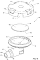
- Figs. 1A through ID show a draining valve 10 in accordance with an example of the presently disclosed subject matter.
- the draining valve 10 includes an inlet nozzle 12 configured to be coupled to a fuel vapor accessory, such as a liquid trap or a tube extending towards a vapor treating device (not shown).
- the inlet nozzle 12 is terminated at one end thereof in a port 15 coupled to a seal holding body 14.
- the seal holding body 14 includes a sealing member 16 held therein and configured to seal the port 15 when in the closed position, and to allow fluid flow through the port when in the open position.
- the seal holding body 14 includes a bottom portion 18 having a diameter larger than the diameter of the port 15, and a cover 20 having a plurality of apertures 23 here illustrated as defined on a side wall 14a of the cover 20.
- the bottom portion 18 and the cover 20 can be configured for snap coupling to one another.
- the sealing member 16, is a sealing disk, made from a sealing material such as rubber, silicone and the like, having a diameter larger than that of the port 15.
- the sealing member 16 defines an inlet face 16a for engaging the port 15 and an outlet face 16b directed towards ambient of the valve, for example the volume of a fuel tank.
- the sealing member 16 In the closed position, the sealing member 16 is disposed over the port 15 thereby precluding fluids from the tank to enter the port 15 and the inlet nozzle 12. In the open position however, the sealing member 16 is configured to move away from the port 15 thereby allowing fluid from the nozzle 12 to exit the draining device 10 through the port and the apertures 23.
- the sealing member 16 is retained inside the body 14 by the cover 20, while the fuel from the inlet nozzle 12 is drained through the apertures 23 in the cover.
- the apertures 23 in the cover 20 can be formed such that they are not covered by the sealing member 16 when the latter is disengaged from the port 15.
- the body 14 may have a side wall 14a defined about the circumference thereof and being larger than the thickness of the sealing member 16.
- the apertures according to this example are defined on the side wall 14a, such that when the sealing member 16 is displaced to the open position thereof whereby the sealing member 16 engages the inner surface of the cover 20, fuel from the nozzle 12 can exit the body 14 through the apertures one the side wall.
- the bottom portion 18 of the seal holding member 14 includes a side wall includes a flange 18a configured to allow snap coupling of the cover 20.
- the flange 18a can be formed with apertures 19 facilitating fluid flow from the seal holding member. It is appreciated that the apertures 19 can be defined on one side of the flange facilitating fluid flow only from that side towards the tank. This way, the draining valve 10 can be disposed inside the tank such that the apertures are downwardly directed allowing thereby the fuel to gravitate towards to the tank.
- the cover 20 can have a diameter larger than that of the sealing member 16 and the apertures 23 can be formed about the periphery of the cover, such that even when the sealing member is urged onto the inner surface of the cover, the apertures remain uncovered allowing fuel from the nozzle to pass through the body 14 and exit therefrom through the apertures 23.
- the sealing member 16 includes a diameter larger than the diameter of the port 15. This way, as explained in detail hereinafter the pressure required to prevent the displacement of the sealing member 16 to its open position is minimal.
- the inlet nozzle 12 includes an insertion end 22 configured to be introduced into an aperture formed in the fuel vapor accessory.
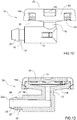
- Fig. 2A is a perspective view of a draining arrangement 50 including the draining valve 10 of Figs. 1A -1D and a pipe segment 52 having an aperture 54 defined by circumferential wall portion 56.
- the pipe segment can be a portion of a fuel vapor accessory or can be coupled to a fuel vapor accessory.
- the aperture 54 which according to the illustrated example is a circular aperture, includes a diameter, which is slightly smaller than that of the insertion end 22.
- the pipe segment 52 is made of a flexible material, which allows for sealing engagement therewith.
- the insertion end 22 can be made of material, which provides sealing engagement with the circumferential wall portion 56 of the aperture 54, when it is inserted therein.
- the insertion end 22 is further configured to engage the circumferential wall portion such that the circumferential wall portion 56 is slightly bent inwardly, thereby forming a ring-shaped fold 58 (shown in Fig. 2B ) providing thereby further sealing engagement between the aperture 54 and the insertion end 22. It is noted that the insertion end 22, when disposed inside the aperture 54, protrudes inside the pipe segment 52, such that the ring-shaped fold 58 bears against the insertion end 22, providing thereby sealing engagements therewith.
- the width of the ring-shaped fold 58 formed by the wall portion 56 of the aperture 54 is determined by the difference between the diameter of the aperture 54 and that of the insertion end 22. That is to say, when the insertion end 22 is disposed inside the aperture 54 the latter is forced thereby to expand by inwardly bending the wall portion 56 to form a ring-shaped fold 58.
- the ring-shaped fold 58 can thus have a width which is configured for providing the required sealing between the pipe segment 52 and the insertion end 22.
- the insertion end 22, according to some examples can be configured to extend inside the pipe segments 52 and to protrude from the inner wall thereof such that the entire width of the ring-shaped fold 58 bears on the insertion end 22. That is to say that the insertion end 22 is configured with a length in accordance with the width of the ring-shaped fold 58.
- the ratio between the diameter of the aperture 54 and that of the insertion end 22, can be determined in accordance with the sealing requirements.
- the ratio can be determined such that the expansion of the insertion end 22 and the expansion of the aperture 54 do not result in a leak.
- the material of the pipe segment 52 has similar characteristics as that of insertion end 22, such that the effect of the fuel thereon is substantially similar.
- the insertion end 22 further includes a bore 24 providing fluid communication between the pipe segment 52 and the inlet nozzle 12, and a cutaway 25 configured to allow fluid gravitating on the wall portion of the pipe segment to enter the bore 24.
- a cutaway 25 configured to allow fluid gravitating on the wall portion of the pipe segment to enter the bore 24.
- the cutaway 25 is configured such that fluid communication is allowed between the bore 24 and the surrounding of the insertion end 22, even when the liquid level in the pipe segment is lower than the height of the protrusion of the insertion end 22 inside the pipe segment 52.
- the cutaway 25 allows draining of liquid from the pipe segment 52 even when the pressure level therein is not higher than the pressure level inside the inlet nozzle 12. That it to say, fluid inside the pipe segment 52 is not urged to drain into the inlet nozzle 12 by the mere pressure inside the pipe segment 52, rather the fluid therein gravitates to the lowest point thereof. Accordingly, the pipe segment 52 can be disposed above the draining valve 10 and the inlet nozzle 12, allowing thereby the fluid therein to gravitate into the inlet nozzle 12.
- the cutaway 25 formed in the insertion end 22 provides a path for the fluid into the bore 24 of the inlet nozzle 12.
- the insertion end 22 further includes a tapered portion 27 defined at the remote end 22a thereof, and configured with a varying outer diameter increasingly changing towards the inlet nozzle 12.
- the diameter at the remote end 22a is smaller or the same as the diameter of the aperture 54 facilitating thereby the insertion of the insertion end 22 through the aperture 54, while the diameter increases towards the inlet nozzle 12. Accordingly, as the insertion end 22 is further pushed through the aperture 54, the increasing diameter of the tapered portion 27 urges the circumferential wall portion 56 of the aperture 54 inwardly forming thereby the ring-shaped fold 58.
- the insertion end 22 further includes a shoulder portion 29 configured with a diameter larger than that of the insertion end 22, such that once the insertion end 22 is disposed inside the aperture 54 and the ring-shaped fold 58 engages the insertion end 22, the shoulder portion 29 abuts the edge of the ring-shaped fold 58.
- the shoulder portion 29 thus, serves as a stop member preventing displacement of the insertion end 22 out of the aperture 54.
- the shoulder portion 29 is defined by the proximal end of the tapered portion 27 which includes a diameter larger than that of the insertion end 22.
- the insertion end 22 includes a tapered portion 27 having a remote end 22a configured with a diameter smaller or substantially the same as that of the aperture 54. The diameter increasingly changed towards the shoulder portion 29 where it is larger than the diameter of the aperture 54 and substantially the same as or larger than the diameter of the ring-shaped fold 58.
- the insertion end 22 further defines an engagement portion 31 defined between the shoulder portion 29 and tapered portion 27, and configured to provides sealing engagement with the ring-shaped fold 58.
- the cutaway 25 according to the present example is formed as a slit formed along the length of the tapered portion 27, extending between the remote end 22a and the shoulder portion 29.
- the length of the engagement portion 31 (denoted in Fig. ID as d) is configured in accordance with the width of the ring-shaped fold 58, such that the ring-shaped fold 58 on one hand sealingly engages the engagement portion 31 and on the other hand abuts against the shoulder portion 29.
- the shoulder portion 29 can be configured to provide further sealing engagement with the ring-shaped fold 58.
- the draining valve 10 can be mounted on a fuel vapor tubing 60 of a fuel vapor system (not shown), for example a tubing which extends between fuel vapor valves and a canister.
- a fuel vapor tubing 60 is mounted inside a fuel tank (not shown), such that the draining valve 10 allows drainage of the fuel inside the tubing into the tank, and precludes the fuel from reaching the canister.
- the draining valve 10 is upwardly disposed such that drainage therethrough is carried out as a siphon, as explained hereinafter.
- the inlet nozzle 12 of the draining valve 10 is filled with fuel and gravitational forces of the fuel are applied over the inside face 16a of the sealing member 16.
- the valve 10 is in the closed position thereof, and fuel vapor from the tank does not enter the fuel vapor system through the draining valve 10. In this position, fuel vapor from the tank can only enter the fuel vapor system through a designated fuel accessory, for example through a liquid trap.
- ⁇ P which designates the difference between the pressure on the inlet face 16a and the pressure at the outlet face 16b, defines the amount of pressure gradient force which is required for overcoming the gravity forces exerted by the liquids inside the port.
- the draining device 10 is mounted to the tubing 30 such that the sealing member 16 is disposed upwards or diagonally upwards. This way, gravitational forces of the sealing member 16 facilitate in maintaining it engaged with the port 15. When the pressure in the tank is reduced however, symphonic drainage is facilitated and the liquid from the tubing exert forces to lift the sealing member 16 thereby allowing the liquids to be discharged through the port 15 and down into the fuel tank.
- the sealing member 16 when the liquid level in the tank is higher than the liquid level inside the tubing 30, the sealing member 16 is maintained in engagement with the port 15 even when the pressure in the tank is substantially equal to the atmospheric pressure. This is due to the fact that the fuel in the tank exert forces on the outside face 16b of the sealing member 16 equal or higher than the forces exerted on the inside face 16a thereof by fuel in the tubing 30.
- the draining device 10 in order to allow drainage of fuel form the tubing 60, the draining device 10 can be disposed at a high point inside the tank, such that only when the fuel level in the tank is near the maximum capacity thereof, the draining device will not open.
- the height of the draining device in the tank can be determined in accordance with the desirable maximum refueling level of the tank.
- the vapor tubing 60 can be a segment of a fuel accessory tube delivering fuel vapor towards a fuel vapor treating device, such as a canister. Any accumulating fuel liquid can be drained through the draining arrangement towards the fuel tank. Accordingly, since the pressure level in the fuel tank is likely to be higher than that in the fuel vapor system, i.e. the pipe segment, the pressure exerts forces on the insertion end 22 urging it further into the aperture (not shown). Thus, when insertion end 22 is further urged inside the aperture, the length of the engagement portion residing inside the pipe segment increases providing thereby more sealing engagement area for engaging the ring-shaped fold (not shown). When the pressure level inside the tank is equal to or lower than that in the vapor tubing 60, draining of the fuel from the pipe segment is allowed.
- the vapor tubing 60 can be made of material providing the required durability capable to maintain its characteristics in fuel conditions. At least the circumferential wall portion, is configured with flexibility allowing forming thereby the ring-shaped fold, and having sealing properties as required given the fuel tank conditions.
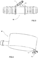
- Fig. 4 shows a draining device 10 mounted on a liquid trap 70, configured for separating fuel liquid from fuel vapor inside the tank.
- the fuel vapor enters the liquid trap 40 through the inlet 42, fuel liquids are accumulated inside the trap, and then can be drained back into the tank (not shown) through the draining device 10.
- the liquid trap 40 can be drained by the draining device 10 when the pressure in the tank is substantially equal to the atmospheric pressure, and when the liquid level in the tank is below the liquid level in the liquid trap.
- the liquid trap in order to facilitate refueling of the tank, can be mounted at a top portion of the fuel tank so that when attempting to refuel the tank, the fuel level therein is lower than the fuel level inside the liquid trap.
- the fuel urges the sealing member to engage the port, thus preventing fuel from entering the fuel vapor system through the draining device.
- the sealing member is urged by the fuel to the closed position thereof.
- the draining device allows disposing thereof at the highest point in the tank hence, allowing the draining device to operate until the fuel level in the tank is nearly at its maximum level. This is due to the fact that draining device can operate as siphon and thus can be disposed upwardly, and that the draining device requires minimal space.
- draining device is configured for passive drainage of fuel from the fuel vapor system.
Landscapes
- Engineering & Computer Science (AREA)
- Mechanical Engineering (AREA)
- Life Sciences & Earth Sciences (AREA)
- Sustainable Development (AREA)
- Sustainable Energy (AREA)
- Chemical & Material Sciences (AREA)
- Combustion & Propulsion (AREA)
- Transportation (AREA)
- General Engineering & Computer Science (AREA)
- Cooling, Air Intake And Gas Exhaust, And Fuel Tank Arrangements In Propulsion Units (AREA)
Claims (15)
- Dispositif de drainage (10) pour drainer du carburant d'un système de vapeur de carburant dans un réservoir de carburant, ledit dispositif de drainage (10) comprenant un orifice (15) configuré pour être couplé à un accessoire de vapeur de carburant et un élément d'étanchéité (16) déplaçable entre une position fermée dans laquelle ledit orifice (15) est fermé par ledit élément d'étanchéité (16) et une position ouverte dans laquelle le carburant dudit accessoire de vapeur de carburant peut être drainé dans le réservoir, dans lequel ledit élément d'étanchéité (16) est déplacé dans ladite position ouverte lorsque la pression dans le réservoir est sensiblement égale à la pression dans l'accessoire de vapeur de carburant et que le niveau de carburant dans le réservoir est au-dessous du niveau de carburant dans ledit accessoire de vapeur de carburant de sorte que ledit élément d'étanchéité (16) est déplacé dans ladite position ouverte par des forces de fluide exercées par ledit carburant dudit accessoire de vapeur de carburant sur ledit élément d'étanchéité,
caractérisé en ce que :
lors du fonctionnement du dispositif de drainage (10), les forces gravitationnelles de l'élément d'étanchéité (16) facilitent le maintien de l'élément d'étanchéité (16) mis en prise avec ledit orifice (15) dans la position fermée. - Dispositif de drainage (10) selon la revendication 1, comprenant en outre une buse d'entrée configurée pour être couplée à l'accessoire de vapeur de carburant et étant en communication de fluide avec ledit orifice.
- Dispositif de drainage (10) selon l'une quelconque des revendications précédentes, dans lequel ledit orifice (15) est défini dans un corps de support de joint d'étanchéité (14) configuré pour supporter ledit élément d'étanchéité (16).
- Dispositif de drainage (10) selon la revendication 3, dans lequel ledit corps de support de joint d'étanchéité (14) comprend une partie inférieure ayant un diamètre supérieur au diamètre de l'orifice (15).
- Dispositif de drainage (10) selon la revendication 4, dans lequel ledit corps de support de joint d'étanchéité (14) comprend un couvercle (20) ayant une pluralité d'ouvertures (23) et configuré pour retenir ledit élément d'étanchéité (16) à l'intérieur du corps de support de joint d'étanchéité (14).
- Dispositif de drainage (10) selon la revendication 5, dans lequel lesdites ouvertures sont définies sur une paroi latérale dudit couvercle (20) ; et/ou
dans lequel lesdites ouvertures (23) sont définies sur une paroi latérale dudit couvercle (20) et dans lequel lesdites ouvertures (23) sont définies sur une circonférence dudit couvercle (20) et ladite paroi latérale est supérieure à l'épaisseur de l'élément d'étanchéité (16) ; et/ou
dans lequel ledit couvercle (20) comprend un diamètre supérieur à celui dudit élément d'étanchéité (16) et dans lequel lesdites ouvertures (23) sont formées autour de la périphérie dudit couvercle (20), de sorte que même lorsque l'élément d'étanchéité (16) est poussé sur la surface interne du couvercle (20), les ouvertures restent, dans lequel ladite partie inférieure comprend une paroi latérale ayant une bride configurée pour permettre le couplage par encliquetage dudit couvercle (20), et dans lequel ladite bride est formée avec des ouvertures pour faciliter l'écoulement de fluide de l'élément de support de joint d'étanchéité. - Dispositif de drainage (10) selon la revendication 5, dans lequel ladite partie inférieure et ledit couvercle (20) sont configurés pour se coupler par encliquetage entre eux.
- Dispositif de drainage (10) selon l'une quelconque des revendications précédentes, dans lequel ledit élément d'étanchéité (16) est un disque d'étanchéité ayant un diamètre supérieur au diamètre de l'orifice (15) et définissant une face d'entrée pour mettre en prise l'orifice (15) et une face de sortie dirigée vers l'environnement du dispositif de drainage (10).
- Dispositif de drainage (10) selon la revendication 5, dans lequel ladite partie inférieure comprend une paroi latérale ayant une bride configurée pour permettre le couplage par encliquetage dudit couvercle (20).
- Dispositif de drainage (10) selon l'une quelconque des revendications 2 à 9, dans lequel ladite buse d'entrée (12) comprend une extrémité d'insertion (22) configurée pour être introduite dans une ouverture formée dans l'accessoire de vapeur de carburant.
- Dispositif de drainage (10) selon la revendication 10, dans lequel :ladite ouverture comprend un diamètre inférieur à celui de ladite extrémité d'insertion (22) ; et/ouladite extrémité d'insertion (22) est configurée pour mettre en prise une partie de paroi circonférentielle de ladite ouverture de sorte que la partie de paroi circonférentielle est légèrement pliée vers l'intérieur, formant ainsi un pli de forme annulaire, et ledit pli de forme annulaire est formé de sorte qu'il s'appuie contre ladite extrémité d'insertion (22) fournissant ainsi des mises en prise d'étanchéité avec cette dernière ; et/ouladite extrémité d'insertion (22) est configurée pour s'étendre à l'intérieur dudit accessoire de vapeur de carburant et pour faire saillie de sa paroi interne ; et/ouladite extrémité d'insertion (22) comprend un alésage (24) fournissant la communication de fluide entre l'accessoire de vapeur de carburant et ladite buse d'entrée (12), et ladite extrémité d'insertion (22) comprend une découpe (25) configurée pour permettre au fluide gravitant sur une partie de paroi dudit accessoire de vapeur de carburant autour de ladite extrémité d'insertion (22) d'entrer dans ledit alésage ; et/ouladite extrémité d'insertion (22) comprend un alésage (24) fournissant la communication de fluide entre l'accessoire de vapeur de carburant et ladite buse d'entrée (12), et ladite extrémité d'insertion (22) comprend une découpe (25) configurée pour permettre au fluide gravitant sur une partie de paroi dudit accessoire de vapeur de carburant autour de ladite extrémité d'insertion (22) d'entrer dans ledit alésage (24), et ladite découpe (25) est configurée de sorte que la communication de fluide est autorisée entre ledit alésage (24) et l'environnement de l'extrémité d'insertion (22), même lorsque le niveau de liquide dans ledit accessoire de vapeur de carburant est inférieur à la hauteur de la saillie de l'extrémité d'insertion (22) à l'intérieur de ce dernier ; et/ouladite extrémité d'insertion (22) comprend un alésage (24) fournissant la communication de fluide entre l'accessoire de vapeur de carburant et ladite buse d'entrée (12), et ladite extrémité d'insertion (22) comprend une découpe (25) configurée pour permettre au fluide gravitant sur une partie de paroi dudit accessoire de vapeur de carburant autour de ladite extrémité d'insertion (22) d'entrer dans ledit alésage (24), et ladite découpe (25) est configurée de sorte que la communication de fluide est autorisée entre ledit alésage (24) et l'environnement de l'extrémité d'insertion (22), même lorsque le niveau de liquide dans ledit accessoire de vapeur de carburant est inférieur à la hauteur de la saillie de l'extrémité d'insertion (22) à l'intérieur de ce dernier, et(a) ladite découpe (24) est configurée pour permettre le drainage du liquide dudit accessoire de vapeur de carburant même lorsque le niveau de pression à l'intérieur de ce dernier n'est pas plus haut que le niveau de pression à l'intérieur de ladite buse d'entrée ou bien (b) ladite découpe (24) fournit une trajectoire pour le fluide dans ledit alésage ; et/ouladite extrémité d'insertion (22) comprend en outre une partie progressivement rétrécie définie au niveau de sa partie à distance (22a), ladite partie progressivement rétrécie (27) étant configurée avec un diamètre externe variable changeant progressivement vers ladite buse d'entrée (12), et/ouladite extrémité d'insertion (22) comprend en outre une partie progressivement rétrécie (27) définie au niveau de son extrémité à distance, ladite partie progressivement rétrécie (27) étant configurée avec un diamètre externe variable changeant progressivement vers ladite buse d'entrée (12), et ladite extrémité à distance (22a) comprend un diamètre inférieur à celui de ladite ouverture (54) facilitant ainsi l'insertion de ladite extrémité d'insertion (22) à travers ladite ouverture ; et/ouladite extrémité d'insertion (22) comprend une partie d'épaulement (29) configurée avec un diamètre supérieur à celui de l'extrémité d'insertion (22) ; et/ouladite extrémité d'insertion (22) comprend une partie d'épaulement (29) configurée avec un diamètre supérieur à celui de l'extrémité d'insertion (22), et ladite partie d'épaulement (29) sert d'élément de butée empêchant le déplacement de ladite extrémité d'insertion (22) hors de ladite ouverture (54), et ladite extrémité d'insertion (22) comprend en outre une partie de mise en prise configurée pour fournir la mise en prise d'étanchéité avec une partie de paroi circonférentielle de ladite ouverture (54).
- Dispositif de drainage (10) selon la revendication 10, dans lequel ladite extrémité d'insertion (22) comprend un alésage (24) fournissant la communication de fluide entre l'accessoire de vapeur de carburant et ladite buse d'entrée (12), et ladite extrémité d'insertion (22) comprend une découpe (25) configurée pour permettre au fluide gravitant sur une partie de paroi dudit accessoire de vapeur de carburant autour de ladite extrémité d'insertion (22) d'entrer dans ledit alésage (24) ; dans lequel ladite découpe (25) est configurée de sorte que la communication de fluide est autorisée entre ledit alésage (24) et l'environnement de l'extrémité d'insertion (22), même lorsque le niveau de liquide dans ledit accessoire de vapeur de carburant est inférieur à la hauteur de la saillie de l'extrémité d'insertion (22) dans ce dernier et dans lequel ladite découpe (25) se présente sous la forme d'une fente formée le long de la longueur de ladite insertion.
- Système de vapeur de carburant ayant un agencement de drainage comprenant :un segment de tuyau (52) ayant une ouverture définie par la partie de paroi circonférentielle ;un dispositif de drainage (10) pour drainer le carburant d'un accessoire de vapeur de carburant dans un réservoir de carburant comprenant :une buse d'entrée (12) ayant une extrémité d'insertion (22) configurée pour être introduite dans ladite ouverture et pour mettre en prise ladite partie de paroi circonférentielle de sorte que ladite partie de paroi circonférentielle est légèrement pliée vers l'intérieur, mettant ainsi en prise de manière étanche ladite extrémité d'insertion (22), ladite extrémité d'insertion (22) comprend un alésage fournissant la communication de fluide entre ledit segment de tuyau (15) et ladite buse d'entrée (12), et une découpe configurée pour permettre au fluide du segment de tuyau (52) d'entrer dans ledit alésage ; etun orifice (15) étant en communication de fluide avec ledit alésage et un élément d'étanchéité (16) déplaçable entre une position fermée dans laquelle ledit orifice (15) est fermé par ledit élément d'étanchéité (16) et une position ouverte dans laquelle le carburant dudit accessoire de vapeur de carburant peut être drainé dans le réservoir ;caractérisé en ce que :ledit élément d'étanchéité (16) est déplacé dans ladite position ouverte lorsque la pression dans le réservoir est sensiblement égale à la pression dans l'accessoire de vapeur de carburant et le niveau de carburant dans le réservoir est au-dessous du niveau de carburant dans ladite accessoire de vapeur de carburant de sorte que ledit élément d'étanchéité est déplacé dans ladite position ouverte par des forces de fluide exercées par ledit carburant dudit accessoire de vapeur de carburant sur ledit élément d'étanchéité (16), eten ce que :
lors du fonctionnement du dispositif de drainage (10), les forces gravitationnelles de l'élément d'étanchéité (16) facilitent le maintien de l'élément d'étanchéité (16) mis en prise avec ledit orifice dans la position fermée. - Système de vapeur de carburant selon la revendication 13, dans lequel :ledit accessoire de vapeur de carburant est un tubage s'étendant entre une valve de vapeur de carburant et un réservoir à charbon actif ; et/ouledit accessoire de vapeur de carburant est un piège à liquide configuré pour séparer le liquide de carburant de la vapeur de carburant à l'intérieur dudit système de vapeur de carburant ; et/ouledit dispositif de drainage (10) est disposé vers le haut par rapport audit réservoir de sorte que le drainage à travers ce dernier est réalisé comme un siphon ; et/oula surface dudit orifice est inférieure à la surface d'une face dudit élément d'étanchéité (16) sur laquelle la pression dudit réservoir est appliquée ; et facultativement ledit élément d'étanchéité (16) est configuré de sorte que la pression requise pour supporter ledit élément d'étanchéité (16) dans sa position fermée est inférieure à la pression requise à la pression requise pour déplacer ledit élément d'étanchéité (16) dans sa position ouverte.
- Réservoir de carburant comprenant un dispositif de drainage (10) selon l'une quelconque des revendications 1 à 12.
Applications Claiming Priority (3)
| Application Number | Priority Date | Filing Date | Title |
|---|---|---|---|
| US201361913456P | 2013-12-09 | 2013-12-09 | |
| US201462056682P | 2014-09-29 | 2014-09-29 | |
| PCT/IL2014/051070 WO2015087320A1 (fr) | 2013-12-09 | 2014-12-08 | Dispositif de vidange |
Publications (2)
| Publication Number | Publication Date |
|---|---|
| EP3092140A1 EP3092140A1 (fr) | 2016-11-16 |
| EP3092140B1 true EP3092140B1 (fr) | 2020-02-05 |
Family
ID=53370702
Family Applications (1)
| Application Number | Title | Priority Date | Filing Date |
|---|---|---|---|
| EP14825189.5A Active EP3092140B1 (fr) | 2013-12-09 | 2014-12-08 | Dispositif de drainage |
Country Status (8)
| Country | Link |
|---|---|
| US (1) | US10183574B2 (fr) |
| EP (1) | EP3092140B1 (fr) |
| JP (1) | JP6591418B2 (fr) |
| KR (1) | KR102194139B1 (fr) |
| CN (1) | CN105793090B (fr) |
| BR (1) | BR112016013024B1 (fr) |
| RU (1) | RU2670363C1 (fr) |
| WO (1) | WO2015087320A1 (fr) |
Cited By (1)
| Publication number | Priority date | Publication date | Assignee | Title |
|---|---|---|---|---|
| US11964553B2 (en) | 2021-05-07 | 2024-04-23 | Hutchinson S.A. | Self-sealing coating for fuel tanks |
Families Citing this family (5)
| Publication number | Priority date | Publication date | Assignee | Title |
|---|---|---|---|---|
| KR102194139B1 (ko) | 2013-12-09 | 2020-12-23 | 라발 에이.씨.에스. 엘티디 | 배출 장치 |
| WO2016051401A1 (fr) | 2014-09-29 | 2016-04-07 | Raval A.C.S. Ltd. | Dispositif de drainage |
| US11255465B2 (en) * | 2016-11-30 | 2022-02-22 | Agilent Technologies, Inc. | Microfluidic check valve and related devices and systems |
| CN112805495B (zh) * | 2018-11-22 | 2023-03-24 | 皮尔伯格泵技术有限责任公司 | 止回阀装置和机动车辆真空泵 |
| CN114294233A (zh) * | 2021-12-31 | 2022-04-08 | 湖南汤普悦斯压缩机科技有限公司 | 一种板凳结构排气阀及其压缩机 |
Family Cites Families (30)
| Publication number | Priority date | Publication date | Assignee | Title |
|---|---|---|---|---|
| US2274276A (en) * | 1938-06-25 | 1942-02-24 | Trico Products Corp | Valve |
| GB851504A (en) * | 1958-01-22 | 1960-10-19 | British Oxygen Gases Ltd | Non-return valve disc retaining cages |
| JPS58192246U (ja) * | 1982-06-15 | 1983-12-21 | 株式会社東陽社製作所 | オイルキヤツプ |
| SE439036B (sv) | 1984-06-21 | 1985-05-28 | Runo Nord | Anordning vid demonterbara vetskebehallare, i synnerhet oljefilter |
| US4852761A (en) | 1988-07-25 | 1989-08-01 | General Motors Corporation | In tank vapor storage canister |
| US4907616A (en) * | 1988-08-15 | 1990-03-13 | G.T. Products, Inc. | Check valve assembly |
| US5704383A (en) | 1994-07-14 | 1998-01-06 | K-Line Industries, Inc. | Tool and method for removing fluid from container |
| IL131051A0 (en) * | 1999-07-23 | 2001-01-28 | Raviv Prec Injection Molding | Valve and method for fitting it to a tank |
| IL134535A0 (en) * | 2000-02-14 | 2001-04-30 | Raviv Prec Injection Molding | Improved filling valve |
| US6681796B2 (en) * | 2000-02-18 | 2004-01-27 | Lloyd Herbert King, Jr. | Drainage valve pipe tap assembly |
| US6557581B2 (en) * | 2001-03-01 | 2003-05-06 | Raviv Precision Injection Molding | Liquid fuel trap |
| US6520200B1 (en) * | 2001-08-16 | 2003-02-18 | Delphi Technologies, Inc. | Liquid/vapor separator assembly for fuel tank |
| US6655403B2 (en) * | 2002-01-08 | 2003-12-02 | Eaton Corporation | Controlling fuel vapor venting in a fuel tank |
| IL165845A0 (en) * | 2004-12-16 | 2006-01-15 | Raval Acs Ltd | Vapor recovery control valve |
| JP4063851B2 (ja) * | 2006-04-13 | 2008-03-19 | 前澤化成工業株式会社 | 吸気弁 |
| JP5366805B2 (ja) * | 2006-07-12 | 2013-12-11 | ラバル エー.シー.エス. リミテッド | 燃料タンクのベントチューブシステム |
| DE102007047170A1 (de) * | 2006-11-24 | 2008-05-29 | Schaeffler Kg | Plattenventil für Zugmittelspannsysteme |
| US7694665B2 (en) * | 2007-02-05 | 2010-04-13 | Raval A.C.S. Ltd. | Liquid vapor separator |
| DE102008014820A1 (de) * | 2007-06-27 | 2009-01-08 | Alfmeier Präzision AG Baugruppen und Systemlösungen | Kraftstofftank für Kraftfahrzeuge |
| CN201192691Y (zh) * | 2008-04-30 | 2009-02-11 | 陈奕 | 一种抽排气装置 |
| US8136548B2 (en) * | 2008-08-08 | 2012-03-20 | Watertite Products, Inc. | Air admittance valve |
| US9403432B2 (en) * | 2010-09-02 | 2016-08-02 | Raval A.C.S. Ltd. | Roll over valve |
| WO2012104850A1 (fr) | 2011-01-31 | 2012-08-09 | Raval A.C.S. Ltd. | Vanne de combustible |
| CN202012648U (zh) * | 2011-04-02 | 2011-10-19 | 西安长庆科技工程有限责任公司 | 低压控制泄放阀 |
| US8689816B2 (en) * | 2011-12-22 | 2014-04-08 | Eaton Corporation | Fuel tank vent valve assembly and method of assembly |
| EP2607135B1 (fr) * | 2011-12-22 | 2014-07-02 | Volvo Car Corporation | Soupape de système de ventilation de carburant |
| JP5901308B2 (ja) * | 2012-01-23 | 2016-04-06 | 株式会社ニフコ | 弁装置 |
| CN104487273B (zh) * | 2012-03-26 | 2018-04-03 | 拉瓦尔A.C.S.公司 | 燃料蒸气阀系统及用于燃料蒸气阀系统的部件 |
| US20150118076A1 (en) * | 2013-10-31 | 2015-04-30 | Emerson Climate Technologies, Inc. | Compressor with improved valve assembly |
| KR102194139B1 (ko) | 2013-12-09 | 2020-12-23 | 라발 에이.씨.에스. 엘티디 | 배출 장치 |
-
2014
- 2014-12-08 KR KR1020167017962A patent/KR102194139B1/ko active IP Right Grant
- 2014-12-08 US US15/035,971 patent/US10183574B2/en active Active
- 2014-12-08 BR BR112016013024-3A patent/BR112016013024B1/pt active IP Right Grant
- 2014-12-08 EP EP14825189.5A patent/EP3092140B1/fr active Active
- 2014-12-08 JP JP2016536899A patent/JP6591418B2/ja active Active
- 2014-12-08 WO PCT/IL2014/051070 patent/WO2015087320A1/fr active Application Filing
- 2014-12-08 CN CN201480066615.2A patent/CN105793090B/zh active Active
- 2014-12-08 RU RU2016125286A patent/RU2670363C1/ru active
Non-Patent Citations (1)
| Title |
|---|
| None * |
Cited By (1)
| Publication number | Priority date | Publication date | Assignee | Title |
|---|---|---|---|---|
| US11964553B2 (en) | 2021-05-07 | 2024-04-23 | Hutchinson S.A. | Self-sealing coating for fuel tanks |
Also Published As
| Publication number | Publication date |
|---|---|
| US20160297296A1 (en) | 2016-10-13 |
| KR102194139B1 (ko) | 2020-12-23 |
| US10183574B2 (en) | 2019-01-22 |
| RU2670363C1 (ru) | 2018-10-22 |
| CN105793090A (zh) | 2016-07-20 |
| KR20160096135A (ko) | 2016-08-12 |
| BR112016013024B1 (pt) | 2023-04-18 |
| EP3092140A1 (fr) | 2016-11-16 |
| WO2015087320A1 (fr) | 2015-06-18 |
| JP2017501331A (ja) | 2017-01-12 |
| BR112016013024A2 (pt) | 2017-08-08 |
| JP6591418B2 (ja) | 2019-10-16 |
| CN105793090B (zh) | 2020-11-06 |
Similar Documents
| Publication | Publication Date | Title |
|---|---|---|
| EP3092140B1 (fr) | Dispositif de drainage | |
| US7726363B2 (en) | Filler tube assembly for a fuel vapor recirculation system | |
| US10226996B2 (en) | Filler neck closure assembly | |
| KR101266653B1 (ko) | 결합된 증기 벤트 또는 팁핑 및 차단 밸브 조립체, 및 엔진 연료 탱크로부터의 증기 배출을 제어하는 방법 | |
| US10065496B2 (en) | Filler neck closure with drainage system | |
| KR20090040432A (ko) | 연료탱크용 벤팅배관 시스템 | |
| JP2017501331A5 (fr) | ||
| US10155654B2 (en) | Vessel overfill protection system | |
| JP6208740B2 (ja) | 燃料蒸気弁システムおよびその構成要素 | |
| EP2499407B1 (fr) | Soupape de gaz | |
| AU2003241639A1 (en) | Filler tube mounted fuel tank refueling valve | |
| US7047997B2 (en) | Fuel tank vent valve | |
| EP3201028B1 (fr) | Arrangement de drainage | |
| EP1171324B1 (fr) | Ensemble de vannes de controle de la limite de remplissage comportant un piege a carburant liquide | |
| WO2009060162A2 (fr) | Dispositif de commande d'écoulement |
Legal Events
| Date | Code | Title | Description |
|---|---|---|---|
| PUAI | Public reference made under article 153(3) epc to a published international application that has entered the european phase |
Free format text: ORIGINAL CODE: 0009012 |
|
| 17P | Request for examination filed |
Effective date: 20160523 |
|
| AK | Designated contracting states |
Kind code of ref document: A1 Designated state(s): AL AT BE BG CH CY CZ DE DK EE ES FI FR GB GR HR HU IE IS IT LI LT LU LV MC MK MT NL NO PL PT RO RS SE SI SK SM TR |
|
| AX | Request for extension of the european patent |
Extension state: BA ME |
|
| DAX | Request for extension of the european patent (deleted) | ||
| GRAP | Despatch of communication of intention to grant a patent |
Free format text: ORIGINAL CODE: EPIDOSNIGR1 |
|
| STAA | Information on the status of an ep patent application or granted ep patent |
Free format text: STATUS: GRANT OF PATENT IS INTENDED |
|
| RIC1 | Information provided on ipc code assigned before grant |
Ipc: B60K 15/035 20060101AFI20190731BHEP Ipc: F16K 24/02 20060101ALI20190731BHEP Ipc: F16K 15/02 20060101ALI20190731BHEP |
|
| INTG | Intention to grant announced |
Effective date: 20190823 |
|
| GRAS | Grant fee paid |
Free format text: ORIGINAL CODE: EPIDOSNIGR3 |
|
| GRAA | (expected) grant |
Free format text: ORIGINAL CODE: 0009210 |
|
| STAA | Information on the status of an ep patent application or granted ep patent |
Free format text: STATUS: THE PATENT HAS BEEN GRANTED |
|
| AK | Designated contracting states |
Kind code of ref document: B1 Designated state(s): AL AT BE BG CH CY CZ DE DK EE ES FI FR GB GR HR HU IE IS IT LI LT LU LV MC MK MT NL NO PL PT RO RS SE SI SK SM TR |
|
| REG | Reference to a national code |
Ref country code: GB Ref legal event code: FG4D |
|
| REG | Reference to a national code |
Ref country code: AT Ref legal event code: REF Ref document number: 1229657 Country of ref document: AT Kind code of ref document: T Effective date: 20200215 |
|
| REG | Reference to a national code |
Ref country code: DE Ref legal event code: R096 Ref document number: 602014060673 Country of ref document: DE |
|
| REG | Reference to a national code |
Ref country code: IE Ref legal event code: FG4D |
|
| REG | Reference to a national code |
Ref country code: CH Ref legal event code: EP |
|
| REG | Reference to a national code |
Ref country code: NL Ref legal event code: MP Effective date: 20200205 |
|
| PG25 | Lapsed in a contracting state [announced via postgrant information from national office to epo] |
Ref country code: NO Free format text: LAPSE BECAUSE OF FAILURE TO SUBMIT A TRANSLATION OF THE DESCRIPTION OR TO PAY THE FEE WITHIN THE PRESCRIBED TIME-LIMIT Effective date: 20200505 Ref country code: FI Free format text: LAPSE BECAUSE OF FAILURE TO SUBMIT A TRANSLATION OF THE DESCRIPTION OR TO PAY THE FEE WITHIN THE PRESCRIBED TIME-LIMIT Effective date: 20200205 Ref country code: PT Free format text: LAPSE BECAUSE OF FAILURE TO SUBMIT A TRANSLATION OF THE DESCRIPTION OR TO PAY THE FEE WITHIN THE PRESCRIBED TIME-LIMIT Effective date: 20200628 Ref country code: RS Free format text: LAPSE BECAUSE OF FAILURE TO SUBMIT A TRANSLATION OF THE DESCRIPTION OR TO PAY THE FEE WITHIN THE PRESCRIBED TIME-LIMIT Effective date: 20200205 |
|
| REG | Reference to a national code |
Ref country code: LT Ref legal event code: MG4D |
|
| PG25 | Lapsed in a contracting state [announced via postgrant information from national office to epo] |
Ref country code: BG Free format text: LAPSE BECAUSE OF FAILURE TO SUBMIT A TRANSLATION OF THE DESCRIPTION OR TO PAY THE FEE WITHIN THE PRESCRIBED TIME-LIMIT Effective date: 20200505 Ref country code: GR Free format text: LAPSE BECAUSE OF FAILURE TO SUBMIT A TRANSLATION OF THE DESCRIPTION OR TO PAY THE FEE WITHIN THE PRESCRIBED TIME-LIMIT Effective date: 20200506 Ref country code: IS Free format text: LAPSE BECAUSE OF FAILURE TO SUBMIT A TRANSLATION OF THE DESCRIPTION OR TO PAY THE FEE WITHIN THE PRESCRIBED TIME-LIMIT Effective date: 20200605 Ref country code: LV Free format text: LAPSE BECAUSE OF FAILURE TO SUBMIT A TRANSLATION OF THE DESCRIPTION OR TO PAY THE FEE WITHIN THE PRESCRIBED TIME-LIMIT Effective date: 20200205 Ref country code: HR Free format text: LAPSE BECAUSE OF FAILURE TO SUBMIT A TRANSLATION OF THE DESCRIPTION OR TO PAY THE FEE WITHIN THE PRESCRIBED TIME-LIMIT Effective date: 20200205 Ref country code: SE Free format text: LAPSE BECAUSE OF FAILURE TO SUBMIT A TRANSLATION OF THE DESCRIPTION OR TO PAY THE FEE WITHIN THE PRESCRIBED TIME-LIMIT Effective date: 20200205 |
|
| PG25 | Lapsed in a contracting state [announced via postgrant information from national office to epo] |
Ref country code: NL Free format text: LAPSE BECAUSE OF FAILURE TO SUBMIT A TRANSLATION OF THE DESCRIPTION OR TO PAY THE FEE WITHIN THE PRESCRIBED TIME-LIMIT Effective date: 20200205 |
|
| PG25 | Lapsed in a contracting state [announced via postgrant information from national office to epo] |
Ref country code: SK Free format text: LAPSE BECAUSE OF FAILURE TO SUBMIT A TRANSLATION OF THE DESCRIPTION OR TO PAY THE FEE WITHIN THE PRESCRIBED TIME-LIMIT Effective date: 20200205 Ref country code: DK Free format text: LAPSE BECAUSE OF FAILURE TO SUBMIT A TRANSLATION OF THE DESCRIPTION OR TO PAY THE FEE WITHIN THE PRESCRIBED TIME-LIMIT Effective date: 20200205 Ref country code: ES Free format text: LAPSE BECAUSE OF FAILURE TO SUBMIT A TRANSLATION OF THE DESCRIPTION OR TO PAY THE FEE WITHIN THE PRESCRIBED TIME-LIMIT Effective date: 20200205 Ref country code: CZ Free format text: LAPSE BECAUSE OF FAILURE TO SUBMIT A TRANSLATION OF THE DESCRIPTION OR TO PAY THE FEE WITHIN THE PRESCRIBED TIME-LIMIT Effective date: 20200205 Ref country code: EE Free format text: LAPSE BECAUSE OF FAILURE TO SUBMIT A TRANSLATION OF THE DESCRIPTION OR TO PAY THE FEE WITHIN THE PRESCRIBED TIME-LIMIT Effective date: 20200205 Ref country code: LT Free format text: LAPSE BECAUSE OF FAILURE TO SUBMIT A TRANSLATION OF THE DESCRIPTION OR TO PAY THE FEE WITHIN THE PRESCRIBED TIME-LIMIT Effective date: 20200205 Ref country code: SM Free format text: LAPSE BECAUSE OF FAILURE TO SUBMIT A TRANSLATION OF THE DESCRIPTION OR TO PAY THE FEE WITHIN THE PRESCRIBED TIME-LIMIT Effective date: 20200205 Ref country code: RO Free format text: LAPSE BECAUSE OF FAILURE TO SUBMIT A TRANSLATION OF THE DESCRIPTION OR TO PAY THE FEE WITHIN THE PRESCRIBED TIME-LIMIT Effective date: 20200205 |
|
| REG | Reference to a national code |
Ref country code: DE Ref legal event code: R097 Ref document number: 602014060673 Country of ref document: DE |
|
| REG | Reference to a national code |
Ref country code: AT Ref legal event code: MK05 Ref document number: 1229657 Country of ref document: AT Kind code of ref document: T Effective date: 20200205 |
|
| PLBE | No opposition filed within time limit |
Free format text: ORIGINAL CODE: 0009261 |
|
| STAA | Information on the status of an ep patent application or granted ep patent |
Free format text: STATUS: NO OPPOSITION FILED WITHIN TIME LIMIT |
|
| 26N | No opposition filed |
Effective date: 20201106 |
|
| PG25 | Lapsed in a contracting state [announced via postgrant information from national office to epo] |
Ref country code: IT Free format text: LAPSE BECAUSE OF FAILURE TO SUBMIT A TRANSLATION OF THE DESCRIPTION OR TO PAY THE FEE WITHIN THE PRESCRIBED TIME-LIMIT Effective date: 20200205 Ref country code: AT Free format text: LAPSE BECAUSE OF FAILURE TO SUBMIT A TRANSLATION OF THE DESCRIPTION OR TO PAY THE FEE WITHIN THE PRESCRIBED TIME-LIMIT Effective date: 20200205 |
|
| PG25 | Lapsed in a contracting state [announced via postgrant information from national office to epo] |
Ref country code: SI Free format text: LAPSE BECAUSE OF FAILURE TO SUBMIT A TRANSLATION OF THE DESCRIPTION OR TO PAY THE FEE WITHIN THE PRESCRIBED TIME-LIMIT Effective date: 20200205 Ref country code: PL Free format text: LAPSE BECAUSE OF FAILURE TO SUBMIT A TRANSLATION OF THE DESCRIPTION OR TO PAY THE FEE WITHIN THE PRESCRIBED TIME-LIMIT Effective date: 20200205 |
|
| REG | Reference to a national code |
Ref country code: CH Ref legal event code: PL |
|
| PG25 | Lapsed in a contracting state [announced via postgrant information from national office to epo] |
Ref country code: MC Free format text: LAPSE BECAUSE OF FAILURE TO SUBMIT A TRANSLATION OF THE DESCRIPTION OR TO PAY THE FEE WITHIN THE PRESCRIBED TIME-LIMIT Effective date: 20200205 |
|
| REG | Reference to a national code |
Ref country code: BE Ref legal event code: MM Effective date: 20201231 |
|
| PG25 | Lapsed in a contracting state [announced via postgrant information from national office to epo] |
Ref country code: LU Free format text: LAPSE BECAUSE OF NON-PAYMENT OF DUE FEES Effective date: 20201208 Ref country code: IE Free format text: LAPSE BECAUSE OF NON-PAYMENT OF DUE FEES Effective date: 20201208 |
|
| PG25 | Lapsed in a contracting state [announced via postgrant information from national office to epo] |
Ref country code: CH Free format text: LAPSE BECAUSE OF NON-PAYMENT OF DUE FEES Effective date: 20201231 Ref country code: LI Free format text: LAPSE BECAUSE OF NON-PAYMENT OF DUE FEES Effective date: 20201231 |
|
| PG25 | Lapsed in a contracting state [announced via postgrant information from national office to epo] |
Ref country code: TR Free format text: LAPSE BECAUSE OF FAILURE TO SUBMIT A TRANSLATION OF THE DESCRIPTION OR TO PAY THE FEE WITHIN THE PRESCRIBED TIME-LIMIT Effective date: 20200205 Ref country code: MT Free format text: LAPSE BECAUSE OF FAILURE TO SUBMIT A TRANSLATION OF THE DESCRIPTION OR TO PAY THE FEE WITHIN THE PRESCRIBED TIME-LIMIT Effective date: 20200205 Ref country code: CY Free format text: LAPSE BECAUSE OF FAILURE TO SUBMIT A TRANSLATION OF THE DESCRIPTION OR TO PAY THE FEE WITHIN THE PRESCRIBED TIME-LIMIT Effective date: 20200205 |
|
| PG25 | Lapsed in a contracting state [announced via postgrant information from national office to epo] |
Ref country code: MK Free format text: LAPSE BECAUSE OF FAILURE TO SUBMIT A TRANSLATION OF THE DESCRIPTION OR TO PAY THE FEE WITHIN THE PRESCRIBED TIME-LIMIT Effective date: 20200205 Ref country code: AL Free format text: LAPSE BECAUSE OF FAILURE TO SUBMIT A TRANSLATION OF THE DESCRIPTION OR TO PAY THE FEE WITHIN THE PRESCRIBED TIME-LIMIT Effective date: 20200205 |
|
| PG25 | Lapsed in a contracting state [announced via postgrant information from national office to epo] |
Ref country code: BE Free format text: LAPSE BECAUSE OF NON-PAYMENT OF DUE FEES Effective date: 20201231 |
|
| PGFP | Annual fee paid to national office [announced via postgrant information from national office to epo] |
Ref country code: GB Payment date: 20231130 Year of fee payment: 10 |
|
| PGFP | Annual fee paid to national office [announced via postgrant information from national office to epo] |
Ref country code: FR Payment date: 20231212 Year of fee payment: 10 Ref country code: DE Payment date: 20231128 Year of fee payment: 10 |