EP1171324B1 - Ensemble de vannes de controle de la limite de remplissage comportant un piege a carburant liquide - Google Patents
Ensemble de vannes de controle de la limite de remplissage comportant un piege a carburant liquide Download PDFInfo
- Publication number
- EP1171324B1 EP1171324B1 EP20000916723 EP00916723A EP1171324B1 EP 1171324 B1 EP1171324 B1 EP 1171324B1 EP 20000916723 EP20000916723 EP 20000916723 EP 00916723 A EP00916723 A EP 00916723A EP 1171324 B1 EP1171324 B1 EP 1171324B1
- Authority
- EP
- European Patent Office
- Prior art keywords
- float
- assembly
- set forth
- vent opening
- stem
- Prior art date
- Legal status (The legal status is an assumption and is not a legal conclusion. Google has not performed a legal analysis and makes no representation as to the accuracy of the status listed.)
- Expired - Lifetime
Links
Images

Classifications
-
- B—PERFORMING OPERATIONS; TRANSPORTING
- B60—VEHICLES IN GENERAL
- B60K—ARRANGEMENT OR MOUNTING OF PROPULSION UNITS OR OF TRANSMISSIONS IN VEHICLES; ARRANGEMENT OR MOUNTING OF PLURAL DIVERSE PRIME-MOVERS IN VEHICLES; AUXILIARY DRIVES FOR VEHICLES; INSTRUMENTATION OR DASHBOARDS FOR VEHICLES; ARRANGEMENTS IN CONNECTION WITH COOLING, AIR INTAKE, GAS EXHAUST OR FUEL SUPPLY OF PROPULSION UNITS IN VEHICLES
- B60K15/00—Arrangement in connection with fuel supply of combustion engines or other fuel consuming energy converters, e.g. fuel cells; Mounting or construction of fuel tanks
- B60K15/03—Fuel tanks
- B60K15/035—Fuel tanks characterised by venting means
- B60K15/03519—Valve arrangements in the vent line
-
- B—PERFORMING OPERATIONS; TRANSPORTING
- B60—VEHICLES IN GENERAL
- B60K—ARRANGEMENT OR MOUNTING OF PROPULSION UNITS OR OF TRANSMISSIONS IN VEHICLES; ARRANGEMENT OR MOUNTING OF PLURAL DIVERSE PRIME-MOVERS IN VEHICLES; AUXILIARY DRIVES FOR VEHICLES; INSTRUMENTATION OR DASHBOARDS FOR VEHICLES; ARRANGEMENTS IN CONNECTION WITH COOLING, AIR INTAKE, GAS EXHAUST OR FUEL SUPPLY OF PROPULSION UNITS IN VEHICLES
- B60K15/00—Arrangement in connection with fuel supply of combustion engines or other fuel consuming energy converters, e.g. fuel cells; Mounting or construction of fuel tanks
- B60K15/03—Fuel tanks
- B60K2015/03328—Arrangements or special measures related to fuel tanks or fuel handling
- B60K2015/0344—Arrangements or special measures related to fuel tanks or fuel handling comprising baffles
-
- B—PERFORMING OPERATIONS; TRANSPORTING
- B60—VEHICLES IN GENERAL
- B60K—ARRANGEMENT OR MOUNTING OF PROPULSION UNITS OR OF TRANSMISSIONS IN VEHICLES; ARRANGEMENT OR MOUNTING OF PLURAL DIVERSE PRIME-MOVERS IN VEHICLES; AUXILIARY DRIVES FOR VEHICLES; INSTRUMENTATION OR DASHBOARDS FOR VEHICLES; ARRANGEMENTS IN CONNECTION WITH COOLING, AIR INTAKE, GAS EXHAUST OR FUEL SUPPLY OF PROPULSION UNITS IN VEHICLES
- B60K15/00—Arrangement in connection with fuel supply of combustion engines or other fuel consuming energy converters, e.g. fuel cells; Mounting or construction of fuel tanks
- B60K15/03—Fuel tanks
- B60K15/035—Fuel tanks characterised by venting means
- B60K15/03504—Fuel tanks characterised by venting means adapted to avoid loss of fuel or fuel vapour, e.g. with vapour recovery systems
- B60K2015/03509—Fuel tanks characterised by venting means adapted to avoid loss of fuel or fuel vapour, e.g. with vapour recovery systems with a droplet separator in the vent line
Definitions
- the present invention relates to a valve which controls the fuel level, the venting and traps fuel vapors from an automotive vehicle fuel tank to a fuel canister, or the like, and which prevents escape of liquid fuel from the fuel tank in the event of rollover of the vehicle.
- a fill limit control valve which is normally disposed in a vehicle fuel tank, frequently comprises a housing having a valve portion for sealing engagement about a hole in a fuel tank and a float portion extending into the fuel tank.
- the type of valve to which the subject invention pertains responds to the level of liquid fuel in the fuel tank, staying open to vent vapor as long as the fuel level is below a predetermined level. These are sometimes referred to as “fill control” or “shutoff” valves, since closing thereof creates a sudden pressure increase in the tank thereby preventing further refueling.
- the valve portion defines a vent opening for venting vapors from the fuel tank and a vapor outlet for conveying fuel vapors to a vapor canister.
- a float is movably supported by the float portion for seating against and closing the vent opening in response to the float rising to a predetermined fuel level. Examples of such prior art assemblies are shown in U. S. Patent Nos. 5,590,697 to Benjey et al. and 5,860,458 to Benjey et al.
- valves are supplemented with a gravity-responsiverollover device supported at the bottom of the float portion for engaging and moving the float upwardly to seal the vent opening in response to a predetermined amount of deviation from vertical, e.g., a rollover.
- a gravity-responsiverollover device supported at the bottom of the float portion for engaging and moving the float upwardly to seal the vent opening in response to a predetermined amount of deviation from vertical, e.g., a rollover.
- a fill limit control valve assembly including the features of the preamble of claim 1 is known from US-A-5 413 137.
- the disadvantages of the prior art may be overcome by providing a fill limit control valve assembly disposed in a vehicle fuel tank.
- the fill limit control valve assembly has a housing having a valve portion for connection to a fuel tank and a float portion for extending into the fuel tank.
- the valve portion defines a vent opening for venting vapors from the fuel tank.
- a float is movably supported by the float portion for movement between an open position spaced from the vent opening and a closed position seating against and sealing the vent opening in response to the float rising to a predetermined fuel level.
- a liquid fuel trap is disposed above the vent opening to limit liquid fuel flow through the vapor outlet.
- the fill limit control valve assembly further includes the features of the characterizing part of claim 1.
- the subject invention provides a fill limit control valve that minimizes and virtually eliminates the undesirable flow of liquid fuel into a vapor canister. Hence, only fuel vapors pass through the valve and into the canister.
- a fill limit control valve assembly having a float which traps vapor during normal fuel filling to enable the float to become buoyant and responsively move to a closed position and which collects liquid fuel when in an inverted rollover condition to prevent buoyancy and responsively move to the closed position.
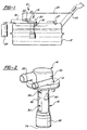
- a fill limit control valve assembly is generally shown at 10 disposed within a vehicle fuel tank 12 in Figure 1.
- the valve assembly 10 includes a housing, generally indicated at 14, having a float portion, generally indicated at 18, adapted for extending into the fuel tank 12.
- the housing 14 includes a mounting cap 20 defining a vapor outlet connector 22 for conveying vapors to a vapor canister 24 via line 26.
- a recirculation pipe 21 is also provided on the cap 20 for recirculating vapors into a filler neck 23 via a second line 25.
- a rollover valve 27 may be mounted to the fuel tank 12 and connected to the vapor canister 24 as is known in the art.
- the mounting cap 20 has a mounting face which abuts the fuel tank 12 to secure the valve assembly 10 to the fuel tank 12 in any suitable manner.
- the vapor canister 24, which is typically a carbon canister, rollover valve 27, and fuel tank 12 are of any suitable design as is known in the art.
- the lines 25, 26 are shown schematically.
- the float portion 18 is a cylindrical column and includes a float 30 movably supported therein.
- the float portion 18 defines a number of openings 82, 83 for providing fluid communication between the fuel tank 12 and the float 30.
- the openings 82 have a rectangular configuration and opening 83 has a triangular configuration.
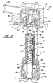
- valve assembly 10 also includes a valve portion 16, adapted for connection to the fuel tank 12.
- the mounting cap 20 encompasses at least a portion of the valve portion 16.
- the valve portion 16 defines a vent opening 28 for venting vapors from the fuel tank 12 to the vapor canister 24 via outlet connector 22 and line 26.
- the valve assembly 10 is characterized by a liquid fuel trap disposed above the vent opening 28 to limit liquid fuel flow through the outlet connector 22.
- the fuel trap includes a baffle barrier 32 surrounding the vent opening 28.
- a return cup 34 having a base 36 overlies the baffle barrier 32 with a depending rim 38 surrounding the baffle barrier 32 for forcing the flow of vapor from the vent opening 28 through a U-turn.
- the return cup 34 includes legs 48 extending downwardly from the rim 38 to support the fuel trap in the valve portion 16.
- the return cup 34 also includes a bullet 46 extending from the base 36 thereof and into the baffle barrier 32 to define an annular passage for dividing the flow of vapors from the vent opening 28.
- the bullet 46 extends above the base 36 of the return cup 34 and an annular flange 50 extends radially of the bullet 46.
- the flange 50 has passages 52 therethrough for the passage of vapors through the flange 50.
- the return cup 34, base 36, bullet 46, legs 48, and flange 50 preferably define an integral discriminator member.
- the discriminator member preferably is formed of a homogeneous organic polymeric material. As appreciated, the discriminator member may include multiple separate parts and may be formed of any suitable material.
- the valve portion 16 includes a bottom 40 supporting the baffle barrier 32 and defining the vent opening 28.
- the bottom 40 of the integral casing defines an annular valve seat 64 extending or projecting downwardly.
- An outer wall 42 extends from the bottom 40 and is spaced from and surrounds the rim 38 for defining a collection reservoir for liquid fuel.
- the baffle barrier 32 includes drain holes 44 for draining liquid from the reservoir back through the vent opening 28.
- the baffle barrier 32, bottom 40 and outer wall 42 are all defined by an integral casing, preferably formed of an organic polymeric material.
- the integral casing may include multiple separate parts and may be formed of any suitable material.
- the legs 48 of the return cup 34 extending downwardly to the bottom 40 for supporting the return cup 34, as well as the entire discriminator member, on the bottom 40.
- the annular flange 50 engages the outer wall 42 to further support the discriminator member to the wall 42 of the valve portion 16.
- the mounting cap 20 surrounds the outer wall 42 of the casing and defines the vapor outlet connector 22 for conveying vapors from the passages 52 in the annular flange 50 of the discriminator member.
- the integral casing and the cap 20 include a first tongue and groove connection 76 interconnecting the integral casing and the cap 20.
- the float portion 18 defines a float cavity in which the float 30 is vertically movable between an open position spaced from the vent opening 28 and a closed position seating against and sealing the vent opening 28.
- the float cavity is defined by an extension of the integral casing which extends downwardly from the bottom 40.
- the float 30 includes a buoyant cylindrical section 31 having a closed top end connected to the top of a stem or shaft 54.
- the cylindrical section 31 is hollow with an open lower end and includes diametrically opposed openings 86 for allowing liquid to pass into a hollow interior of the cylindrical section 31. Openings 86 are spaced from the closed upper end of cylindrical section 31 so that a vapor chamber is defined having a sufficient volume to enable the float 30 to float in response to the filling liquid fuel.
- a valve seal 56 is secured to the upper closed end of the cylindrical section 31 for sealing engagement with the vent opening 28 to close the float 30 when in the closed position.
- the seal 56 is flexible and snapped into engagement with a button integral with the top end of the cylindrical section 31.
- the seal 56 engages the valve seat 64, which extends into the float cavity.
- the stem 54 extends from the top end of the cylindrical section 31 of the float 30 downwardly to a lower end 58.
- a guide disk 60 extends about the lower end of the float cavity and has an opening receiving the stem 54 for guiding and stabilizing movement of the float 30 in the float cavity.
- the guide disk 60 includes openings 84 for allowing liquid to pass therethrough between the funnel-shaped element 68 and the float cavity.
- a spring 62 acts between the guide disk 60 and the top of the stem 54 for biasing the stem 54, as well as the entire float 30, toward the closed position.
- a skirt 66 depends from the float portion 18 of the integral casing.
- a gravity responsive device 67 is supported in the skirt 66 of the float portion 18.
- the gravity responsive device 67 is supported below the guide disk 60 for engaging the distal end 58 of the stem 54 and for moving the float 30 upwardly to seal with the seat 64 and close the vent opening 28 in response to a predetermined amount of deviation from vertical.
- the gravity responsive device 67 includes a funnel shaped element 68 extending from a large diameter adjacent the guide disk 60 to a small diameter at the bottom thereof.
- a ball-seat opening 70 is defined in the small diameter and a ball 72, preferably made of steel, is normally disposed over the ball-seat opening 70.
- a support wheel 74 extends radially from the small diameter to engage the skirt 66 to support the funnel-shaped element 68 in the skirt 66.
- the guide disk 60 is also supported in the skirt 66.
- a second tongue and groove connection 78 interconnects the disk 60 and the skirt 66.
- the wheel 74 and the funnel-shaped element 68 are integral and consist of an organic polymeric material and include a third tongue and groove connection 80 interconnecting the wheel 74 and the skirt 66.
- the invention provides a fill limit control valve assembly with an integrated liquid/vapor discriminator member.
- the fuel level in the tank 12 rises and vapor is displaced. This causes a constant vapor flow to the canister 24.
- the vapors pass through the openings 82 and upwardly through the float cavity.
- the vapors then pass through the vent opening 28 and are then diverted by the bullet 46.
- the vapors pass over the baffle barrier 32 between the barrier 32 and base 36.
- the vapors are forced to complete a U-turn by the depending rim 38.
- the vapors then continue upward through the passages 52 in the flange 50 and out through the connector 22 and into the vapor canister 24.
- the vapors are purified by the canister 24 and exhausted to the atmosphere.
- the baffle barrier 32 in conjunction with the return cup 34, condenses fuel and fuel mist that travels with the vapor flow and retains any liquid in the reservoir established between the wall 42 and the baffle barrier 32. As appreciated, a small amount of fuel mist and/or liquid may become trapped in the reservoir. This retained mist and/or liquid drains back into the tank 12 through the drain holes or slits 44 in the baffle barrier 32 once the vent opening 28 is reopened.
- liquid fuel also passes through the openings 82 and into the float cavity.
- the liquid fuel also passes through openings 84 in the guide disk 60 such that liquid fuel is accumulating below and within the float 30.
- liquid fuel is disposed between the stem 54 and the cylindrical section 31.
- the displaced vapor within the float 30 passes out of opening 86 within the cylindrical section 31. This process continues until the level of liquid fuel within the fuel tank 12 reaches the level above the opening 86 in the cylindrical section 31.
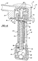
- the float 30 will move from the open position, as shown in Figure 3, to the closed position, as shown in Figure 4.
- the upward movement of the float 30 occurs because of the buoyancy of the float 30, created by the trapped vapor, in relation to the rising liquid and the upward pushing force from the spring 62.
- the float 30 completely rises and, with the assistance of the spring 62, seals the seat 64 with the seal 56.
- the float 30 is therefore movably supported by the float portion 18 for moving to the closed position seating against and sealing the vent opening 28 in response to the float 30 rising to a predetermined fuel level, i.e., full.
- the fuel tank 12 Upon closure of the vent opening 28, the fuel tank 12 no longer has an exhaust avenue for the vapor such that pressure builds up in the tank 12 and corresponding filler neck 23. This pressure build-up triggers the filling nozzle to shut off and stops the refilling of the fuel tank 12.
- the level of liquid fuel will lower which subsequently lowers the float 30 within the float cavity.
- the liquid fuel will flow out of the float cavity through the openings 82.
- the vent opening 28 is reopened such that any trapped mist and liquid can flow back into the float cavity through the drain holes 44.
- the surface tension of the fuel in the float 30 would cause the fuel to remain in the cylindrical float 30 except that the stem 54 helps to purge the fuel by breaking this surface tension.
- the steel ball 72 will disengage from the ball-seat opening 70.
- the steel ball 72 starts to roll out of the normal position when the vehicle is tilted more than 70°.
- the ball 72 engages the distal end 58 of the stem 54 to push the stem 54 into the closed position sealing the fuel tank 12.
- the ball 72 may be of any suitable design, material and weight so long as the stem 54 is adequately pushed upward against the valve seat 64.
- the cylindrical section 31 of float 3 0 will be in an inverted condition and will therefore fill with liquid fuel such that the float 30 is no longer buoyant.
- the float 30 is responsively forced to the closed position, against the valve seat 64 by the spring 62 preventing fuel from passing through opening 28.
Claims (23)
- Ensemble de soupape de contrôle de limite de remplissage (10) conçu pour être disposé dans un réservoir de carburant de véhicule (12), ledit ensemble de soupape (10) comprenant :un boítier (14) ayant une partie soupape (16) avec un raccord de sortie (22) conçu pour être raccordé à un réservoir de carburant (12), et une partie flotteur (18) conçue pour s'étendre dans le réservoir de carburant (12),ladite partie soupape (16) définissant un orifice d'évent (28) pour évacuer les vapeurs du réservoir de carburant (12) par ledit raccord de sortie (22),un flotteur (30) supporté en mouvement par ladite partie flotteur (18), conçue pour se déplacer entre une position ouverte espacée dudit orifice d'évent (28) et une position fermée s'appuyant contre ledit orifice d'évent (28) et fermant alors celui-ci, etun séparateur de carburant liquide disposé au-dessus dudit orifice d'évent (28) pour limiter l'écoulement de carburant liquide à travers celui-ci vers ledit raccord de sortie (22), caractérisé en ce queledit séparateur de carburant liquide comprend un déflecteur (32) entourant ledit orifice d'évent (28), et une coupelle de retour (34) ayant une base (36) recouvrant ledit déflecteur (32) avec un rebord dépendant (38) entourant ledit déflecteur (32) pour forcer l'écoulement desdites vapeurs dudit orifice d'évent (28) à travers un coude en U, et des jambes (48) s'étendant vers le bas à partir dudit rebord (38) pour supporter ledit séparateur de carburant liquide dans ladite partie soupape (16).
- Ensemble selon la revendication 1, dans lequel ladite partie soupape (16) inclut une partie inférieure (40) supportant ledit déflecteur (32) et définissant ledit orifice d'évent (28), et une paroi extérieure (42) s'étendant à partir de ladite partie inférieure (40) en étant espacée dudit rebord (38) et entourant celui-ci pour définir un réservoir de récupération sous ledit rebord (38).
- Ensemble selon la revendication 2, dans lequel ledit déflecteur (32) inclut des trous d'évacuation (44) pour évacuer le liquide à partir dudit réservoir à travers ledit orifice d'évent (28).
- Ensemble selon la revendication 3, dans lequel ladite coupelle de retour (34) inclut une partie arrondie (46) s'étendant à partir de ladite base (36) de celle-ci et à l'intérieur dudit déflecteur (32) afin de définir un passage annulaire pour séparer ledit écoulement de vapeurs dudit orifice d'évent (28).
- Ensemble selon la revendication 4, incluant en outre des jambes (48) s'étendant vers le bas à partir dudit rebord (38) vers ladite partie inférieure (40) pour supporter ladite coupelle de retour (34) sur ladite partie inférieure (40).
- Ensemble selon la revendication 5, dans lequel ladite partie arrondie (46) s'étend au-dessus de ladite base (36) de ladite coupelle de retour (34), et inclut une bride annulaire (50) s'étendant radialement par rapport à ladite partie arrondie (46) pour s'engager avec ladite paroi extérieure (42), ladite bride (50) définissant des passages (52) au travers de celle-ci pour le passage desdites vapeurs à travers ladite bride (50).
- Ensemble selon la revendication 6, dans lequel ladite partie flotteur (18) définit une cavité de flotteur dans laquelle ledit flotteur (30) peut être déplacé verticalement entre lesdites positions ouverte et fermée, ledit flotteur (30) incluant une section cylindrique (31) qui sépare la vapeur pendant le remplissage normal du carburant pour permettre au flotteur (30) de se déplacer en réponse à cette condition vers la position fermée, et qui récupère le carburant liquide lorsqu'il se trouve dans un état de retournement inversé pour se déplacer en réponse à cette condition vers la position fermée.
- Ensemble selon la revendication 7, dans lequel ledit flotteur (30) inclut en outre un joint de soupape (56) à une extrémité supérieure pour assurer un engagement d'étanchéité avec ledit orifice d'évent (28) afin de fermer celui-ci lorsqu'il se trouve dans ladite position fermée, et une tige (54) s'étendant à partir de ladite extrémité supérieure dudit flotteur (30) vers le bas jusqu'à une extrémité distale (58).
- Ensemble selon la revendication 8, incluant en outre un disque de guidage (60) s'étendant sur la largeur de la cavité de flotteur et étant en engagement de coulissement avec ladite tige (54) pour guider et stabiliser ledit déplacement dudit flotteur (30) dans ladite cavité de flotteur entre lesdites positions.
- Ensemble selon la revendication 9, dans lequel ledit joint de soupape (56) est supporté par ladite partie supérieure de ladite section cylindrique flottante (31).
- Ensemble selon la revendication 10, incluant en outre un dispositif apte à répondre à la gravité (67), supporté par ladite partie flotteur (18) sous ledit disque de guidage (60) pour s'engager avec ladite extrémité distale (58) de ladite tige (54), et pour déplacer ledit flotteur (30) vers le haut afin d'étanchéifier ledit orifice d'évent (28) en réponse à une quantité prédéterminée de déviation par rapport à la verticale.
- Ensemble selon la revendication 11, incluant en outre un ressort (62) réagissant entre ledit disque de guidage (60) et ladite partie supérieure de ladite tige (54) pour solliciter ladite tige (54) vers ladite position fermée.
- Ensemble selon la revendication 12, dans lequel ledit déflecteur (32), ladite partie inférieure (40) et ladite paroi extérieure (42) définissent un boítier intégral.
- Ensemble selon la revendication 13, dans lequel ladite coupelle de retour (34), ladite base (36), ladite partie arrondie (46), et ladite bride (50) définissent un élément discriminateur intégral.
- Ensemble selon la revendication 14, dans lequel ledit boítier (14) inclut un chapeau de fixation (20) entourant ladite paroi extérieure (42) dudit boítier, et définissant ledit raccord de sortie (22) pour acheminer lesdites vapeurs à partir de ladite bride annulaire (50) dudit élément discriminateur.
- Ensemble selon la revendication 15, dans lequel ladite partie inférieure (40) dudit boítier intégral définit un siège de soupape annulaire (64) s'étendant vers le bas à l'intérieur de ladite cavité de flotteur.
- Ensemble selon la revendication 16, dans lequel ledit boítier intégral s'étend vers le bas à partir de ladite partie inférieure (40) pour définir en outre ladite cavité de flotteur avec une jupe (66) dépendant de celle-ci.
- Ensemble selon la revendication 17, dans lequel ledit dispositif apte à répondre à la gravité (67) est supporté par ladite jupe (66).
- Ensemble selon la revendication 18, dans lequel ledit dispositif apte à répondre à la gravité (67) inclut un élément en forme d'entonnoir (68) s'étendant depuis un grand diamètre adjacent audit disque de guidage (60) jusqu'à un petit diamètre, ainsi qu'un orifice à siège de bille (70) dans ledit petit diamètre, et une bille (72) disposée normalement sur ledit orifice à siège de bille (70).
- Ensemble selon la revendication 19, dans lequel ledit disque de guidage (60) est supporté par ladite jupe (66).
- Ensemble selon la revendication 20, incluant une roue de support (74) s'étendant radialement à partir dudit petit diamètre pour s'engager avec ladite jupe (66) afin de supporter ledit élément en forme d'entonnoir (68) dans ladite jupe (66).
- Ensemble selon la revendication 21, dans lequel ladite partie flotteur (18) inclut des orifices (82) pour permettre au liquide de passer au travers depuis le réservoir de carburant (12) dans ladite cavité de flotteur, ledit disque de guidage (60) incluant des orifices (84) pour permettre au liquide de passer à travers ledit élément en forme d'entonnoir (68) vers ladite cavité de flotteur, et ladite section cylindrique flottante (31) étant creuse avec une extrémité distale ouverte et incluant des orifices (86) pour permettre au liquide de passer dans une partie intérieure creuse de ladite section cylindrique flottante (31).
- Ensemble selon la revendication 22, dans lequel ledit boítier intégral et ledit chapeau (20) consistent en une matière polymère organique et incluent un premier assemblage à rainure et languette (76) accouplant ledit boítier intégral et ledit chapeau (20), ledit disque (60) consistant en une matière polymère organique et incluant un deuxième assemblage à rainure et languette (78) accouplant ledit disque (60) et ladite jupe (66), ladite roue (74) et ledit élément en forme d'entonnoir (68) étant d'une pièce et consistant en une matière polymère organique et incluant un troisième assemblage à rainure et languette (80) accouplant ladite roue (74) et ladite jupe (66).
Applications Claiming Priority (3)
| Application Number | Priority Date | Filing Date | Title |
|---|---|---|---|
| US12956099P | 1999-04-16 | 1999-04-16 | |
| US129560P | 1999-04-16 | ||
| PCT/CA2000/000381 WO2000063042A1 (fr) | 1999-04-16 | 2000-04-11 | Ensemble de vannes de controle de la limite de remplissage comportant un piege a carburant liquide |
Publications (2)
| Publication Number | Publication Date |
|---|---|
| EP1171324A1 EP1171324A1 (fr) | 2002-01-16 |
| EP1171324B1 true EP1171324B1 (fr) | 2004-10-27 |
Family
ID=22440585
Family Applications (1)
| Application Number | Title | Priority Date | Filing Date |
|---|---|---|---|
| EP20000916723 Expired - Lifetime EP1171324B1 (fr) | 1999-04-16 | 2000-04-11 | Ensemble de vannes de controle de la limite de remplissage comportant un piege a carburant liquide |
Country Status (6)
| Country | Link |
|---|---|
| EP (1) | EP1171324B1 (fr) |
| AT (1) | ATE280688T1 (fr) |
| AU (1) | AU3799100A (fr) |
| CA (1) | CA2366923A1 (fr) |
| DE (1) | DE60015317T2 (fr) |
| WO (1) | WO2000063042A1 (fr) |
Families Citing this family (3)
| Publication number | Priority date | Publication date | Assignee | Title |
|---|---|---|---|---|
| DE10063389A1 (de) | 2000-12-19 | 2002-06-20 | Daimler Chrysler Ag | Lüftungs- und/oder Druckausgleichssystem für einen Kraftstoffbehälter |
| DE10063414A1 (de) * | 2000-12-19 | 2002-06-27 | Kautex Textron Gmbh & Co Kg | Kraftstoffbehälter |
| DE10318353B4 (de) * | 2003-04-23 | 2016-02-04 | GM Global Technology Operations LLC (n. d. Ges. d. Staates Delaware) | Kraftstoffabscheideeinrichtung für Kraftstoffbehälter in Kraftfahrzeugen |
Family Cites Families (5)
| Publication number | Priority date | Publication date | Assignee | Title |
|---|---|---|---|---|
| GB2238041A (en) * | 1989-11-17 | 1991-05-22 | Ford Motor Co | Fuel tank venting |
| US5413137A (en) * | 1994-02-14 | 1995-05-09 | Borg-Warner Automotive, Inc. | Fuel vapor vent assembly with liquid trap |
| US5590697A (en) | 1994-08-24 | 1997-01-07 | G. T. Products, Inc. | Onboard vapor recovery system with two-stage shutoff valve |
| US5687756A (en) * | 1995-11-08 | 1997-11-18 | Borg-Warner Automotive, Inc. | Vehicle refueling valve |
| US5809976A (en) | 1995-11-29 | 1998-09-22 | Siemens Canada Limited | Vent control valving for fuel vapor recovery system |
-
2000
- 2000-04-11 AT AT00916723T patent/ATE280688T1/de not_active IP Right Cessation
- 2000-04-11 WO PCT/CA2000/000381 patent/WO2000063042A1/fr active IP Right Grant
- 2000-04-11 EP EP20000916723 patent/EP1171324B1/fr not_active Expired - Lifetime
- 2000-04-11 CA CA002366923A patent/CA2366923A1/fr not_active Abandoned
- 2000-04-11 DE DE60015317T patent/DE60015317T2/de not_active Expired - Fee Related
- 2000-04-11 AU AU37991/00A patent/AU3799100A/en not_active Abandoned
Also Published As
| Publication number | Publication date |
|---|---|
| EP1171324A1 (fr) | 2002-01-16 |
| DE60015317T2 (de) | 2005-11-10 |
| DE60015317D1 (de) | 2004-12-02 |
| WO2000063042A1 (fr) | 2000-10-26 |
| AU3799100A (en) | 2000-11-02 |
| ATE280688T1 (de) | 2004-11-15 |
| CA2366923A1 (fr) | 2000-10-26 |
Similar Documents
| Publication | Publication Date | Title |
|---|---|---|
| US6708713B1 (en) | Fill limit control valve assembly having a liquid fuel trap | |
| US4991615A (en) | Tank pressure control apparatus | |
| US5669361A (en) | Vehicle refueling valve | |
| US6918405B2 (en) | Fill limit vent valve | |
| EP0667253B1 (fr) | Ensemble de ventilation des vapeurs de carburant avec piège de liquide | |
| US4724861A (en) | Fuel tank venting | |
| US6508263B1 (en) | Float operated fuel tank vapor vent valve | |
| US6941966B2 (en) | Outflow-limiting device of fuel tank | |
| US4630749A (en) | Fuel fill tube with vapor vent and overfill protection | |
| US5065782A (en) | Tank venting control assembly | |
| US5694968A (en) | Tank venting control system | |
| US6035884A (en) | Liquid fuel baffle for vent apparatus | |
| US5044397A (en) | Tank pressure control apparatus | |
| EP0648637A1 (fr) | Dispositif de recyclage de vapeurs | |
| US6848463B2 (en) | Vapor vent valve | |
| US6532983B2 (en) | System for venting a liquid tank | |
| EP1642760A2 (fr) | Entlüftung eines Kraftstofftanks mit höhenverstellbarem Einfüllstopp-Anschluss | |
| US20070000542A1 (en) | Fuel tank valve | |
| US20100282335A1 (en) | Fuel vapor vent valve with dynamic pressure relief | |
| WO1995031369A1 (fr) | Ensemble vanne a limite de remplissage | |
| KR19990044928A (ko) | 연료 증기 회수를 위한 제어 밸브 및 시스템 | |
| US6612324B2 (en) | Fill limit vapor valve with variable vapor venting capability | |
| KR20060107382A (ko) | 증기 벤트/팁핑 및 차단 밸브 조립체 및 증기 배출 제어방법 | |
| EP1493605A2 (fr) | Contrôle de la recirculation de vapeur pendant le remplissage d'un réservoir avec un buse de distribution à travers un tube de remplissage | |
| EP1171324B1 (fr) | Ensemble de vannes de controle de la limite de remplissage comportant un piege a carburant liquide |
Legal Events
| Date | Code | Title | Description |
|---|---|---|---|
| PUAI | Public reference made under article 153(3) epc to a published international application that has entered the european phase |
Free format text: ORIGINAL CODE: 0009012 |
|
| 17P | Request for examination filed |
Effective date: 20011017 |
|
| AK | Designated contracting states |
Kind code of ref document: A1 Designated state(s): AT BE CH CY DE DK ES FI FR GB GR IE IT LI LU MC NL PT SE |
|
| AX | Request for extension of the european patent |
Free format text: AL;LT;LV;MK;RO;SI |
|
| GRAP | Despatch of communication of intention to grant a patent |
Free format text: ORIGINAL CODE: EPIDOSNIGR1 |
|
| RBV | Designated contracting states (corrected) |
Designated state(s): AT DE GB |
|
| GRAS | Grant fee paid |
Free format text: ORIGINAL CODE: EPIDOSNIGR3 |
|
| GRAA | (expected) grant |
Free format text: ORIGINAL CODE: 0009210 |
|
| AK | Designated contracting states |
Kind code of ref document: B1 Designated state(s): AT DE GB |
|
| PG25 | Lapsed in a contracting state [announced via postgrant information from national office to epo] |
Ref country code: AT Free format text: LAPSE BECAUSE OF FAILURE TO SUBMIT A TRANSLATION OF THE DESCRIPTION OR TO PAY THE FEE WITHIN THE PRESCRIBED TIME-LIMIT Effective date: 20041027 |
|
| REG | Reference to a national code |
Ref country code: GB Ref legal event code: FG4D |
|
| REG | Reference to a national code |
Ref country code: IE Ref legal event code: FG4D |
|
| REF | Corresponds to: |
Ref document number: 60015317 Country of ref document: DE Date of ref document: 20041202 Kind code of ref document: P |
|
| PGFP | Annual fee paid to national office [announced via postgrant information from national office to epo] |
Ref country code: GB Payment date: 20050404 Year of fee payment: 6 |
|
| PGFP | Annual fee paid to national office [announced via postgrant information from national office to epo] |
Ref country code: DE Payment date: 20050418 Year of fee payment: 6 |
|
| LTIE | Lt: invalidation of european patent or patent extension |
Effective date: 20041027 |
|
| PLBE | No opposition filed within time limit |
Free format text: ORIGINAL CODE: 0009261 |
|
| STAA | Information on the status of an ep patent application or granted ep patent |
Free format text: STATUS: NO OPPOSITION FILED WITHIN TIME LIMIT |
|
| 26N | No opposition filed |
Effective date: 20050728 |
|
| PG25 | Lapsed in a contracting state [announced via postgrant information from national office to epo] |
Ref country code: GB Free format text: LAPSE BECAUSE OF NON-PAYMENT OF DUE FEES Effective date: 20060411 |
|
| PG25 | Lapsed in a contracting state [announced via postgrant information from national office to epo] |
Ref country code: DE Free format text: LAPSE BECAUSE OF NON-PAYMENT OF DUE FEES Effective date: 20061101 |
|
| GBPC | Gb: european patent ceased through non-payment of renewal fee |
Effective date: 20060411 |