EP3091663A2 - Capteur de proximite electromagnetique et procede de detection d'un objet cible - Google Patents
Capteur de proximite electromagnetique et procede de detection d'un objet cible Download PDFInfo
- Publication number
- EP3091663A2 EP3091663A2 EP16164732.6A EP16164732A EP3091663A2 EP 3091663 A2 EP3091663 A2 EP 3091663A2 EP 16164732 A EP16164732 A EP 16164732A EP 3091663 A2 EP3091663 A2 EP 3091663A2
- Authority
- EP
- European Patent Office
- Prior art keywords
- state
- sensor signal
- target object
- sensor
- level
- Prior art date
- Legal status (The legal status is an assumption and is not a legal conclusion. Google has not performed a legal analysis and makes no representation as to the accuracy of the status listed.)
- Granted
Links
Images

Classifications
-
- H—ELECTRICITY
- H03—ELECTRONIC CIRCUITRY
- H03K—PULSE TECHNIQUE
- H03K17/00—Electronic switching or gating, i.e. not by contact-making and –breaking
- H03K17/94—Electronic switching or gating, i.e. not by contact-making and –breaking characterised by the way in which the control signals are generated
- H03K17/945—Proximity switches
- H03K17/95—Proximity switches using a magnetic detector
- H03K17/952—Proximity switches using a magnetic detector using inductive coils
-
- G—PHYSICS
- G01—MEASURING; TESTING
- G01D—MEASURING NOT SPECIALLY ADAPTED FOR A SPECIFIC VARIABLE; ARRANGEMENTS FOR MEASURING TWO OR MORE VARIABLES NOT COVERED IN A SINGLE OTHER SUBCLASS; TARIFF METERING APPARATUS; MEASURING OR TESTING NOT OTHERWISE PROVIDED FOR
- G01D5/00—Mechanical means for transferring the output of a sensing member; Means for converting the output of a sensing member to another variable where the form or nature of the sensing member does not constrain the means for converting; Transducers not specially adapted for a specific variable
- G01D5/12—Mechanical means for transferring the output of a sensing member; Means for converting the output of a sensing member to another variable where the form or nature of the sensing member does not constrain the means for converting; Transducers not specially adapted for a specific variable using electric or magnetic means
- G01D5/14—Mechanical means for transferring the output of a sensing member; Means for converting the output of a sensing member to another variable where the form or nature of the sensing member does not constrain the means for converting; Transducers not specially adapted for a specific variable using electric or magnetic means influencing the magnitude of a current or voltage
- G01D5/20—Mechanical means for transferring the output of a sensing member; Means for converting the output of a sensing member to another variable where the form or nature of the sensing member does not constrain the means for converting; Transducers not specially adapted for a specific variable using electric or magnetic means influencing the magnitude of a current or voltage by varying inductance, e.g. by a movable armature
-
- H—ELECTRICITY
- H03—ELECTRONIC CIRCUITRY
- H03K—PULSE TECHNIQUE
- H03K2217/00—Indexing scheme related to electronic switching or gating, i.e. not by contact-making or -breaking covered by H03K17/00
- H03K2217/94—Indexing scheme related to electronic switching or gating, i.e. not by contact-making or -breaking covered by H03K17/00 characterised by the way in which the control signal is generated
- H03K2217/9401—Calibration techniques
- H03K2217/94026—Automatic threshold calibration; e.g. threshold automatically adapts to ambient conditions or follows variation of input
Definitions
- the invention relates to an electromagnetic proximity sensor and to a method for detecting a target object according to the preamble of claims 1 and 10, respectively.
- Proximity sensors detect the presence or approach of objects at a sensing distance.
- the object is often referred to as a target or target in this context.
- goals with certain characteristics are recognized.
- an inductive proximity sensor recognizes conductive, in practice primarily metallic targets, while a capacitive proximity sensor responds to dielectric properties.
- Proximity sensors are very often used as non-contact switches, with a switching state in the presence and the other switching state in the absence of a target in the switching distance.
- the proximity sensors are often exposed to a harsh environment with high temperature fluctuations, pollution and wear especially of the object to be detected by mechanical stress, which also amplifies aging phenomena of the sensor. Such effects are referred to collectively as drifts.
- Another problem is the so-called installation conditions.
- An inductive sensor reacts to all metallic objects in its vicinity, not just to the object to be detected.
- a capacitive sensor is also affected by the dielectric properties of the environment. Similar effects also exist with magnetic sensors or microwave sensors. Therefore, the switching distance changes under certain circumstances in a new environment or due to drift very strong, the sensor used as a switch is therefore no longer in practice or does not turn on anymore.
- the problem increases with large switching distances, because then the sensitivity of the sensors increases.
- optical sensors is out of the DE 10 2011 050 119 A1 It is known to determine from a time series of the received signal at least the first two moments of the distribution, to classify therefrom a state and to derive therefrom a switching signal.
- solutions of optical sensors can not be easily transferred to the proximity sensors considered here.
- the light signal of the optical sensor has no comparable distance dependence, and such sensors therefore have no switching distance. This does not mean that an optical sensor could not measure distances and switch at certain distances, but an optical distance measurement is done in a completely different way, for example, by triangulation or light transit time determination and is not related to the intensity of the sensor signal.
- An electromagnetic proximity sensor generates with a sensor element a sensor signal dependent on the distance of a target object and evaluates this with a switching threshold in order to determine the presence of the target object at a switching distance.
- the invention is based on the basic idea of adapting the switching threshold to a level of the sensor signal which changes as a result of drifting. For this purpose, a presence level is measured while the target object is detected as present, or an absence level when no target object influences the sensor signal. Changes in presence or absence levels are then not due to the distance of the target object, but the drifts, and accordingly, the drifts can be compensated by adjusting the switching threshold.
- the invention has the advantage that an unintentional shifting of the switching distance and in particular a functional failure is prevented.
- the sensor remains reliably operational even in harsh environments. It is possible to compensate for drifts such as wear and aging phenomena on the sensor or its holder, contamination or temperature fluctuations, and adaptation to deviations from normal installation or changes in the installation environment, in particular during runtime.
- the sensor element comprises a transmitting coil with an excitation circuit and a receiving coil, wherein the sensor signal is derived from the voltage across the receiving coil, or the sensor element comprises a resonant circuit with a coil, wherein the sensor signal is derived from the voltage across the resonant circuit.
- the evaluation unit is preferably designed to adapt the switching threshold in accordance with the changes in the absence level.
- the switching threshold is thus tracked according to a drift of the absence level. As a result, the switching distance remains constant despite drifting. This procedure is also called autocorrection. Influences of the drifts on the switching distance of the sensor are eliminated, and thus the availability and robustness of the detection increases enormously.
- the evaluation unit is designed to redetermine the switching threshold in an adaptation with high S / N ratio to absence level and presence level, in particular to their Average. This is not about keeping the switching distance constant, but the sensor sets its switching threshold and thus its switching distance so tightly that a particularly robust switching behavior is ensured, which allows maximum immunity to interference. This procedure is also called autodetection.
- Such a sensor has no fixed switching distance more, and thus the switching distance must not be adjusted. The sensor only has a maximum possible detection range. This significantly reduces the variance of the sensor models, with corresponding cost advantages for the manufacturer and the customer.
- the evaluation unit is preferably designed to compare a time profile of the sensor signal with a reference curve during an expected movement of the target object and thus to determine times for detecting the absence level and / or the presence level.
- the approaching motion of the target object is repeated cyclically. Even otherwise, typical approach scenarios can be known and learned.
- the sensor recognizes by comparison with such a reference curve, which changes of the sensor signal are due to the movement of the target object. Therefore, the sensor is able to determine times at which the target is present or absent to determine the appropriate levels for threshold adjustment.
- the evaluation unit is preferably designed to determine times for detecting the absence level and / or the presence level on the basis of an examination of the derivative of the sensor signal.
- Drifts have a significantly different effect on the derivative of the sensor signal than the movement of the target. In general, drifts are slower and always rectified as in wear, aging or contamination, or they are one-off effects as in a conversion. Therefore, consideration of the derivative allows determination of times to determine the absence or absence level and, in particular, prevents these levels from being determined during movement of the target object and thus mistakenly adjusting the threshold according to a largely random position of the target instead of drifting.
- the evaluation unit is preferably designed to examine the sensor signal for an expected time sequence of the sign of the derivative.
- An example of a sequence is an initially negative derivative, which then goes directly or with a plateau at zero derivative into a positive derivative and drops back to zero. This then corresponds to a target cycle of an approaching and departing target object.
- the value zero together with a certain tolerance environment, should also be understood as a sign of the derivative. Whether the derivative is positive or negative also depends on the sensor principle. It is always assumed that a sensor in which the sensor signal is weakened as with an inductive sensor with increasing proximity of the target. For other higher-level sensors on nearby targets, the signs should be reversed accordingly.
- the evaluation unit is preferably designed to derive conditions for a state transition in a state machine from the sign of the derivative of the sensor signal, the absence level and / or the presence level being determined in a further state in a first state.
- a target cycle of approaching and subsequently removing a target object is hereby modeled as a state machine or classifier, the sign of the derivation determining the condition for a state transition or class change.
- Such a state machine is very easy to implement and enables a robust determination of states or times in which the absence or presence levels required for the adaptation of the threshold are determined.
- the presence level can be measured in the third state.
- FIG. 1a shows an inductive proximity sensor 10 in a very simplified schematic representation.
- the proximity sensor 10 comprises a sensor element 12 which generates a sensor signal which is evaluated by an evaluation unit 14 with a switching threshold.
- This switching threshold corresponds to a specific switching distance 16, which in FIG. 1a indicated by an arrow and a dashed line.
- a switching output 18 generates an on or off signal depending on whether the sensor signal is above or below the threshold. It can be realized with two different thresholds for switching on and off a hysteresis.
- an inductive proximity sensor 10 The working principle of an inductive proximity sensor 10 is known per se and will therefore not be explained in detail.
- a common principle is to accommodate a transmitting coil and a receiving coil in the sensor element 12.
- An excitation circuit connected to the transmitting coil builds up an alternating field in the transmitting coil, which in turn induces a voltage in the receiving coil.
- the evaluation unit 14 uses the voltage amplitude as sensor signal.
- an inductive sensor with a different number and arrangement of coils.
- another proven principle is the provision of only one resonant circuit with a coil, in which case the voltage across this resonant circuit forms the sensor signal.
- FIGS. 1a to 1d show a typical so-called target cycle in which a target object 20 moves towards and away from the proximity sensor 10.
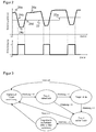
- FIG. 2 shows in the upper part an exemplary time profile of the sensor signal during several target cycles and in the lower part an associated time profile of the switching signal.
- the switching signal is produced by evaluating the sensor signal with the threshold 22, which ultimately results in a 1-bit-valued digitization or binarization means.
- the sensor signal remains as in FIG. 2 to be recognized at an upper constant value, which is referred to as absence level 24a in the context of this description.
- absence level 24a in the context of this description.
- the target object 20 is only at a distance from the proximity sensor 10, which corresponds at most to the switching distance 16. While the target object 20 remains at this distance, the sensor signal forms the FIG. 2 another constant range, which is referred to as presence level 24c in the context of this description. If the target object 20 subsequently as in Figure 1d removed again, the sensor signal returns FIG. 2 via a rising edge 24d back to the absence level 24a, and it closes after a certain pause the next target cycle.
- the movement of the target object 20 can, of course, also take place differently than shown, also transversely or with a transverse component.
- the description based on an inductive proximity sensor 10 is to be understood only as an example to which the invention is not limited.
- a corresponding behavior of the sensor signal also occurs with other electromagnetic proximity sensors, such as capacitive, magnetic or microwave sensors. However, it may then be the case that the sensor signal behaves exactly in the opposite direction, ie rises when the target object 20 approaches.
- the evaluation and the drift compensation according to the invention explained below can take this into account by means of a corresponding change of sign.
- the threshold 22 is adjusted.
- the evaluation unit 14 may analyze the temporal change of the sensor signal to determine when the target 20 is absent and has no influence on the sensor signal and when it is present.
- a possible goal of this evaluation is the situations of FIGS. 1a or 1c to determine the absence level 24a and / or the presence level 24c. For this analysis, it is necessary to consider the sensor signal changing with the distance of the target object 20, and not just the switching signal. In addition, the fact can be exploited that the drift effects affect the sensor signal almost identically regardless of the position of the target object 20.
- An absence or absence of the target object 20 can preferably be detected by an analysis of the derivative of the sensor signal.
- a target cycle that is, passing through the target object 20 through a detection range of the proximity sensor 10, as in FIG Figure 1a-d illustrates, generates a characteristic derivative pattern. Drift effects do not show this derivation pattern, but cause, for example, only a very small derivative (temperature), always have the same sign (wear, aging) or appear only as a single event (installation change).
- the initially constant derivative becomes negative for a target cycle, followed by a plateau with derivative zero and a positive derivative, which drops back to zero.
- the pattern of this sequence of signs of the derivative can be clearly detected and distinguished from changes caused by noise or drift.
- the evaluation unit 14 can assume that the target object 20 is absent at this moment and, accordingly, the absence level 24a is present.
- a rapid drift is superimposed on the rapid changes of the sensor signal due to the movement of the target object 20, for example due to temperature change.
- the derivative also deviates from zero by the drift, but this is certainly distinguished by the described recognition of the sequence of the signs.
- FIG. 3 illustrates a way to model the analysis of the derivative in a state machine and thereby allow easy evaluation.
- the states and conditions for state transitions are in FIG. 1 and 2 comprehensibly.
- the first state “waiting for target approach” is like in FIG. 1a no target 20 near the proximity sensor 10, and the sensor signal corresponds to the absence level 24a.
- the transition to a second state “Target is approaching” according to Figure 1 b takes place when the derivative becomes negative in the falling edge 24b of the sensor signal.
- the state machine enters a third state "Target is there" according to Figure 1c above. In this state, the presence level can be measured.
- the transition to a fourth state "target moves away” then takes place in accordance with Figure 1d .
- the second state there is no measurable phase in which the target object 20 is present, but it goes away immediately, omitting the third state, and so the second state goes directly to the fourth state for positive derivation.
- the presence level 24c can then be estimated as the minimum of the sensor signal.
- absence levels 24a and / or presence levels 24c may be stored.
- the return to the first state may also be due to cancellation due to time lapse (time out), this being done in FIG. 3 by way of example for the third and fourth states.
- the evaluation via a state machine or classifier is simple and robust. But there are also alternative evaluations conceivable, for example by neural networks.
- absence level 24a and / or presence level 24c allows the threshold 22 to be adapted to drift effects, as shown in FIG. 2 is exemplified at an adaptation point 22a.
- two preferred embodiments are presented in more detail below.
- the proximity sensor 10 should always switch in the same switching distance 16, despite the drifts.
- the proximity sensor 10 is mounted, for example, at room temperature under certain installation conditions and has at this moment a user-acceptable switching interval 16.
- the evaluation unit 14 determines now initially and repeatedly, for example cyclically at fixed intervals or after each fully recognized target run, the absence level 24a. If this value has changed from the previously stored value, the threshold 22 is modified by the difference between the old value and the new value. At least the last value used for a threshold adjustment or the initial value is stored for later threshold adjustments.
- the threshold 22 may, but does not have to be, changed directly by the difference in the absence levels 24a, but may also take into account a scaling factor or nonlinearities.
- the proximity sensor 10 does not have a fixed switching distance 16, but always adapts the switching distance 16 so that the presence of a target object 20 with the greatest possible immunity to interference is detected.
- the threshold 22 is not only tracked, but redefined on the basis of the absence level 24a and the presence level 24c.
- An exemplary Robust threshold is achieved by placing the threshold 22 at the middle between the absence level 24a and the presence level 24c.
- the proximity sensor 10 has the goal of robust detection as possible and waives a fixed switching distance 16.
- the proximity sensor 10 determines itself a switching distance 16, so to speak itself. This has the advantage that installation influences are automatically eliminated immediately after commissioning and also the material of the target object 20 for a secure detection does not matter.
- Such proximity sensors 10 also need to be designed only for a maximum possible and not a fixed switching distance 16. All switching distances smaller than the maximum possible are covered by one and the same device. As a result, the variance, logistics and procurement costs are considerably reduced both by the manufacturer and by the user of the proximity sensor 10.
Landscapes
- Physics & Mathematics (AREA)
- General Physics & Mathematics (AREA)
- Electronic Switches (AREA)
- Geophysics And Detection Of Objects (AREA)
Applications Claiming Priority (1)
| Application Number | Priority Date | Filing Date | Title |
|---|---|---|---|
| DE102015107221.1A DE102015107221B4 (de) | 2015-05-08 | 2015-05-08 | Elektromagnetischer Näherungssensor und Verfahren zur Erfassung eines Zielobjekts |
Publications (3)
| Publication Number | Publication Date |
|---|---|
| EP3091663A2 true EP3091663A2 (fr) | 2016-11-09 |
| EP3091663A3 EP3091663A3 (fr) | 2017-01-04 |
| EP3091663B1 EP3091663B1 (fr) | 2017-09-20 |
Family
ID=55752186
Family Applications (1)
| Application Number | Title | Priority Date | Filing Date |
|---|---|---|---|
| EP16164732.6A Active EP3091663B1 (fr) | 2015-05-08 | 2016-04-11 | Capteur de proximite electromagnetique et procede de detection d'un objet cible |
Country Status (3)
| Country | Link |
|---|---|
| US (1) | US20160329892A1 (fr) |
| EP (1) | EP3091663B1 (fr) |
| DE (1) | DE102015107221B4 (fr) |
Families Citing this family (5)
| Publication number | Priority date | Publication date | Assignee | Title |
|---|---|---|---|---|
| TWM552413U (zh) * | 2016-02-25 | 2017-12-01 | 米沃奇電子工具公司 | 包括輸出位置感測器之動力工具 |
| DE102017118083B4 (de) | 2017-08-09 | 2022-11-24 | Sick Ag | Sensor zur Erfassung eines Objekts und Verfahren zum Einstellen eines Schaltpunktes |
| JP6911672B2 (ja) * | 2017-09-25 | 2021-07-28 | オムロン株式会社 | 近接センサの製造方法および近接センサの製造システム |
| DE102019121802B3 (de) * | 2019-08-13 | 2020-09-17 | Ifm Electronic Gmbh | Anordnung und Verfahren zur Einstellung eines binären magnetischen Positionssensors |
| DE102021114974A1 (de) | 2021-06-10 | 2022-12-15 | Infineon Technologies Ag | Vorrichtungen und Verfahren zur Positionsdetektion durch einen3D-Magnetfeldsensor |
Citations (1)
| Publication number | Priority date | Publication date | Assignee | Title |
|---|---|---|---|---|
| DE102011050119A1 (de) | 2011-05-05 | 2012-11-08 | Sick Ag | Optoelektronischer Sensor und Verfahren zur Objektfeststellung |
Family Cites Families (9)
| Publication number | Priority date | Publication date | Assignee | Title |
|---|---|---|---|---|
| DE19844663C2 (de) * | 1998-09-29 | 2000-09-21 | Siemens Ag | Schaltungsanordnung und Verfahren zum Einstellen von Schaltpunkten eines Entscheiders |
| US7132766B2 (en) * | 2003-03-25 | 2006-11-07 | Rockwell Automation Technologies, Inc. | Method and apparatus for providing a switching signal in the presence of noise |
| TW200949632A (en) * | 2008-05-22 | 2009-12-01 | Prospect Technology Corp | A trigger-threshold adaptable and auto-adjustable capacitive induction-type keying device |
| JP5584442B2 (ja) * | 2009-08-26 | 2014-09-03 | パナソニック株式会社 | 物体検知装置およびそれを備えた照明システム |
| US8918209B2 (en) * | 2010-05-20 | 2014-12-23 | Irobot Corporation | Mobile human interface robot |
| FR2985034A1 (fr) * | 2011-12-23 | 2013-06-28 | Continental Automotive France | Procede d'adaptation d'un seuil de detection d'un capteur d'arbre a cames pour un vehicule automobile |
| WO2014191379A1 (fr) * | 2013-05-28 | 2014-12-04 | Inventio Ag | Porte d'ascenseur pourvue d'un contacteur |
| BR112015032365A2 (pt) * | 2013-08-19 | 2017-07-25 | Touchsensor Tech Llc | método de filtração de sensor capacitivo |
| WO2015031009A2 (fr) * | 2013-08-30 | 2015-03-05 | Allegro Microsystems, Llc | Circuits et procédés de production d'un signal de seuil utilisé dans un détecteur de mouvement en fonction d'au moins un multiple commun d'un ensemble de quantités possibles de caractéristiques sur une cible |
-
2015
- 2015-05-08 DE DE102015107221.1A patent/DE102015107221B4/de not_active Expired - Fee Related
-
2016
- 2016-04-11 EP EP16164732.6A patent/EP3091663B1/fr active Active
- 2016-04-29 US US15/141,944 patent/US20160329892A1/en not_active Abandoned
Patent Citations (1)
| Publication number | Priority date | Publication date | Assignee | Title |
|---|---|---|---|---|
| DE102011050119A1 (de) | 2011-05-05 | 2012-11-08 | Sick Ag | Optoelektronischer Sensor und Verfahren zur Objektfeststellung |
Also Published As
| Publication number | Publication date |
|---|---|
| US20160329892A1 (en) | 2016-11-10 |
| DE102015107221A1 (de) | 2016-11-10 |
| DE102015107221B4 (de) | 2018-04-12 |
| EP3091663A3 (fr) | 2017-01-04 |
| EP3091663B1 (fr) | 2017-09-20 |
Similar Documents
| Publication | Publication Date | Title |
|---|---|---|
| EP3091663B1 (fr) | Capteur de proximite electromagnetique et procede de detection d'un objet cible | |
| EP3303955B1 (fr) | Appareil électroménager équipé d'un capteur de pression différentielle | |
| AT407983B (de) | Vorrichtung zum erfassen der positionen von schwenkbaren teilen einer weiche | |
| EP2169700B1 (fr) | Procédé et dispositif de surveillance d'un processus de commutation et composant de relais | |
| WO2012016868A1 (fr) | Procédé et dispositif pour la surveillance de l'environnement pour un véhicule | |
| WO2012140265A2 (fr) | Dispositif et procédé de détection d'objets électriquement conducteurs | |
| EP0783699B1 (fr) | Capteur actif de mouvements | |
| EP0116850A1 (fr) | Système d'impression avec induit plongeur commandé par microprocesseur et contenant un détecteur opto-électronique | |
| EP3346177B1 (fr) | Dispositif de sécurité | |
| EP1754021B1 (fr) | Procede pour corriger les erreurs d'un signal de detection de trajectoire | |
| EP2884233B1 (fr) | Mesure de paramètres dans un entraînement électromagnétique d'un appareil de commutation | |
| DE102006005463A1 (de) | Optoelektronische Vorrichtung | |
| EP2112530A2 (fr) | Procédé de détection d'objets à l'aide d'un capteur | |
| DE102012012865A1 (de) | Kapazitiver Sensor für eine Kollisionsschutzvorrichtung | |
| EP3073463B1 (fr) | Dispositif de detection de vehicule | |
| EP4030199A1 (fr) | Unité inductive de détection de proximité et procédé de détermination d'une propriété d'objet d'un corps métallique de détection | |
| DE4438507C2 (de) | Verfahren zur Überwachung eines elektronischen Schaltgerätes | |
| WO2017118717A1 (fr) | Procédé d'analyse électronique d'un signal variant dans le temps | |
| DE102016208649A1 (de) | Vorrichtung und Verfahren zum Erfassen einer Lageänderung eines Signalgeberrads | |
| DE102020135158B4 (de) | Verfahren zum Betreiben eines induktiven Sicherheitsschalters und Vorrichtung | |
| EP1885065B1 (fr) | Commutateur de proximité inductif et procédé pour son fonctionnement | |
| DE19948892A1 (de) | Impulsdetektor und Verfahren zur Detektion von sinusförmigen Impulsen | |
| DE102021000157A1 (de) | lnduktive Annäherungssensoreinheit und Verfahren zur Störungsüberprüfung bei einer induktiven Annäherungssensoreinheit | |
| DE102008005064A1 (de) | Optoelektronisches Detektionsverfahren und optoelektronischer Detektor | |
| EP3513274B1 (fr) | Procédé pour reconnaître un effleurement d'un élément sensible capacitif |
Legal Events
| Date | Code | Title | Description |
|---|---|---|---|
| PUAI | Public reference made under article 153(3) epc to a published international application that has entered the european phase |
Free format text: ORIGINAL CODE: 0009012 |
|
| AK | Designated contracting states |
Kind code of ref document: A2 Designated state(s): AL AT BE BG CH CY CZ DE DK EE ES FI FR GB GR HR HU IE IS IT LI LT LU LV MC MK MT NL NO PL PT RO RS SE SI SK SM TR |
|
| AX | Request for extension of the european patent |
Extension state: BA ME |
|
| PUAL | Search report despatched |
Free format text: ORIGINAL CODE: 0009013 |
|
| AK | Designated contracting states |
Kind code of ref document: A3 Designated state(s): AL AT BE BG CH CY CZ DE DK EE ES FI FR GB GR HR HU IE IS IT LI LT LU LV MC MK MT NL NO PL PT RO RS SE SI SK SM TR |
|
| AX | Request for extension of the european patent |
Extension state: BA ME |
|
| RIC1 | Information provided on ipc code assigned before grant |
Ipc: H03K 17/95 20060101AFI20161130BHEP |
|
| 17P | Request for examination filed |
Effective date: 20170127 |
|
| RBV | Designated contracting states (corrected) |
Designated state(s): AL AT BE BG CH CY CZ DE DK EE ES FI FR GB GR HR HU IE IS IT LI LT LU LV MC MK MT NL NO PL PT RO RS SE SI SK SM TR |
|
| GRAP | Despatch of communication of intention to grant a patent |
Free format text: ORIGINAL CODE: EPIDOSNIGR1 |
|
| INTG | Intention to grant announced |
Effective date: 20170517 |
|
| GRAS | Grant fee paid |
Free format text: ORIGINAL CODE: EPIDOSNIGR3 |
|
| GRAA | (expected) grant |
Free format text: ORIGINAL CODE: 0009210 |
|
| AK | Designated contracting states |
Kind code of ref document: B1 Designated state(s): AL AT BE BG CH CY CZ DE DK EE ES FI FR GB GR HR HU IE IS IT LI LT LU LV MC MK MT NL NO PL PT RO RS SE SI SK SM TR |
|
| REG | Reference to a national code |
Ref country code: GB Ref legal event code: FG4D Free format text: NOT ENGLISH |
|
| REG | Reference to a national code |
Ref country code: CH Ref legal event code: EP |
|
| REG | Reference to a national code |
Ref country code: AT Ref legal event code: REF Ref document number: 930857 Country of ref document: AT Kind code of ref document: T Effective date: 20171015 |
|
| REG | Reference to a national code |
Ref country code: IE Ref legal event code: FG4D Free format text: LANGUAGE OF EP DOCUMENT: GERMAN |
|
| REG | Reference to a national code |
Ref country code: DE Ref legal event code: R096 Ref document number: 502016000148 Country of ref document: DE |
|
| REG | Reference to a national code |
Ref country code: NL Ref legal event code: MP Effective date: 20170920 |
|
| PG25 | Lapsed in a contracting state [announced via postgrant information from national office to epo] |
Ref country code: FI Free format text: LAPSE BECAUSE OF FAILURE TO SUBMIT A TRANSLATION OF THE DESCRIPTION OR TO PAY THE FEE WITHIN THE PRESCRIBED TIME-LIMIT Effective date: 20170920 Ref country code: LT Free format text: LAPSE BECAUSE OF FAILURE TO SUBMIT A TRANSLATION OF THE DESCRIPTION OR TO PAY THE FEE WITHIN THE PRESCRIBED TIME-LIMIT Effective date: 20170920 Ref country code: NO Free format text: LAPSE BECAUSE OF FAILURE TO SUBMIT A TRANSLATION OF THE DESCRIPTION OR TO PAY THE FEE WITHIN THE PRESCRIBED TIME-LIMIT Effective date: 20171220 Ref country code: SE Free format text: LAPSE BECAUSE OF FAILURE TO SUBMIT A TRANSLATION OF THE DESCRIPTION OR TO PAY THE FEE WITHIN THE PRESCRIBED TIME-LIMIT Effective date: 20170920 Ref country code: HR Free format text: LAPSE BECAUSE OF FAILURE TO SUBMIT A TRANSLATION OF THE DESCRIPTION OR TO PAY THE FEE WITHIN THE PRESCRIBED TIME-LIMIT Effective date: 20170920 |
|
| REG | Reference to a national code |
Ref country code: LT Ref legal event code: MG4D |
|
| PG25 | Lapsed in a contracting state [announced via postgrant information from national office to epo] |
Ref country code: GR Free format text: LAPSE BECAUSE OF FAILURE TO SUBMIT A TRANSLATION OF THE DESCRIPTION OR TO PAY THE FEE WITHIN THE PRESCRIBED TIME-LIMIT Effective date: 20171221 Ref country code: BG Free format text: LAPSE BECAUSE OF FAILURE TO SUBMIT A TRANSLATION OF THE DESCRIPTION OR TO PAY THE FEE WITHIN THE PRESCRIBED TIME-LIMIT Effective date: 20171220 Ref country code: LV Free format text: LAPSE BECAUSE OF FAILURE TO SUBMIT A TRANSLATION OF THE DESCRIPTION OR TO PAY THE FEE WITHIN THE PRESCRIBED TIME-LIMIT Effective date: 20170920 Ref country code: RS Free format text: LAPSE BECAUSE OF FAILURE TO SUBMIT A TRANSLATION OF THE DESCRIPTION OR TO PAY THE FEE WITHIN THE PRESCRIBED TIME-LIMIT Effective date: 20170920 |
|
| PG25 | Lapsed in a contracting state [announced via postgrant information from national office to epo] |
Ref country code: NL Free format text: LAPSE BECAUSE OF FAILURE TO SUBMIT A TRANSLATION OF THE DESCRIPTION OR TO PAY THE FEE WITHIN THE PRESCRIBED TIME-LIMIT Effective date: 20170920 |
|
| PG25 | Lapsed in a contracting state [announced via postgrant information from national office to epo] |
Ref country code: PL Free format text: LAPSE BECAUSE OF FAILURE TO SUBMIT A TRANSLATION OF THE DESCRIPTION OR TO PAY THE FEE WITHIN THE PRESCRIBED TIME-LIMIT Effective date: 20170920 Ref country code: CZ Free format text: LAPSE BECAUSE OF FAILURE TO SUBMIT A TRANSLATION OF THE DESCRIPTION OR TO PAY THE FEE WITHIN THE PRESCRIBED TIME-LIMIT Effective date: 20170920 Ref country code: ES Free format text: LAPSE BECAUSE OF FAILURE TO SUBMIT A TRANSLATION OF THE DESCRIPTION OR TO PAY THE FEE WITHIN THE PRESCRIBED TIME-LIMIT Effective date: 20170920 |
|
| PG25 | Lapsed in a contracting state [announced via postgrant information from national office to epo] |
Ref country code: SK Free format text: LAPSE BECAUSE OF FAILURE TO SUBMIT A TRANSLATION OF THE DESCRIPTION OR TO PAY THE FEE WITHIN THE PRESCRIBED TIME-LIMIT Effective date: 20170920 Ref country code: IS Free format text: LAPSE BECAUSE OF FAILURE TO SUBMIT A TRANSLATION OF THE DESCRIPTION OR TO PAY THE FEE WITHIN THE PRESCRIBED TIME-LIMIT Effective date: 20180120 Ref country code: SM Free format text: LAPSE BECAUSE OF FAILURE TO SUBMIT A TRANSLATION OF THE DESCRIPTION OR TO PAY THE FEE WITHIN THE PRESCRIBED TIME-LIMIT Effective date: 20170920 Ref country code: EE Free format text: LAPSE BECAUSE OF FAILURE TO SUBMIT A TRANSLATION OF THE DESCRIPTION OR TO PAY THE FEE WITHIN THE PRESCRIBED TIME-LIMIT Effective date: 20170920 |
|
| REG | Reference to a national code |
Ref country code: DE Ref legal event code: R097 Ref document number: 502016000148 Country of ref document: DE |
|
| PLBE | No opposition filed within time limit |
Free format text: ORIGINAL CODE: 0009261 |
|
| STAA | Information on the status of an ep patent application or granted ep patent |
Free format text: STATUS: NO OPPOSITION FILED WITHIN TIME LIMIT |
|
| PG25 | Lapsed in a contracting state [announced via postgrant information from national office to epo] |
Ref country code: DK Free format text: LAPSE BECAUSE OF FAILURE TO SUBMIT A TRANSLATION OF THE DESCRIPTION OR TO PAY THE FEE WITHIN THE PRESCRIBED TIME-LIMIT Effective date: 20170920 |
|
| 26N | No opposition filed |
Effective date: 20180621 |
|
| PG25 | Lapsed in a contracting state [announced via postgrant information from national office to epo] |
Ref country code: MT Free format text: LAPSE BECAUSE OF FAILURE TO SUBMIT A TRANSLATION OF THE DESCRIPTION OR TO PAY THE FEE WITHIN THE PRESCRIBED TIME-LIMIT Effective date: 20170920 |
|
| PG25 | Lapsed in a contracting state [announced via postgrant information from national office to epo] |
Ref country code: MC Free format text: LAPSE BECAUSE OF FAILURE TO SUBMIT A TRANSLATION OF THE DESCRIPTION OR TO PAY THE FEE WITHIN THE PRESCRIBED TIME-LIMIT Effective date: 20170920 Ref country code: SI Free format text: LAPSE BECAUSE OF FAILURE TO SUBMIT A TRANSLATION OF THE DESCRIPTION OR TO PAY THE FEE WITHIN THE PRESCRIBED TIME-LIMIT Effective date: 20170920 |
|
| REG | Reference to a national code |
Ref country code: BE Ref legal event code: MM Effective date: 20180430 |
|
| REG | Reference to a national code |
Ref country code: IE Ref legal event code: MM4A |
|
| PG25 | Lapsed in a contracting state [announced via postgrant information from national office to epo] |
Ref country code: LU Free format text: LAPSE BECAUSE OF NON-PAYMENT OF DUE FEES Effective date: 20180411 |
|
| PG25 | Lapsed in a contracting state [announced via postgrant information from national office to epo] |
Ref country code: BE Free format text: LAPSE BECAUSE OF NON-PAYMENT OF DUE FEES Effective date: 20180430 |
|
| PG25 | Lapsed in a contracting state [announced via postgrant information from national office to epo] |
Ref country code: FR Free format text: LAPSE BECAUSE OF NON-PAYMENT OF DUE FEES Effective date: 20180430 Ref country code: IE Free format text: LAPSE BECAUSE OF NON-PAYMENT OF DUE FEES Effective date: 20180411 |
|
| PG25 | Lapsed in a contracting state [announced via postgrant information from national office to epo] |
Ref country code: TR Free format text: LAPSE BECAUSE OF FAILURE TO SUBMIT A TRANSLATION OF THE DESCRIPTION OR TO PAY THE FEE WITHIN THE PRESCRIBED TIME-LIMIT Effective date: 20170920 |
|
| PG25 | Lapsed in a contracting state [announced via postgrant information from national office to epo] |
Ref country code: PT Free format text: LAPSE BECAUSE OF FAILURE TO SUBMIT A TRANSLATION OF THE DESCRIPTION OR TO PAY THE FEE WITHIN THE PRESCRIBED TIME-LIMIT Effective date: 20170920 |
|
| PG25 | Lapsed in a contracting state [announced via postgrant information from national office to epo] |
Ref country code: HU Free format text: LAPSE BECAUSE OF FAILURE TO SUBMIT A TRANSLATION OF THE DESCRIPTION OR TO PAY THE FEE WITHIN THE PRESCRIBED TIME-LIMIT; INVALID AB INITIO Effective date: 20160411 Ref country code: CY Free format text: LAPSE BECAUSE OF FAILURE TO SUBMIT A TRANSLATION OF THE DESCRIPTION OR TO PAY THE FEE WITHIN THE PRESCRIBED TIME-LIMIT Effective date: 20170920 Ref country code: RO Free format text: LAPSE BECAUSE OF FAILURE TO SUBMIT A TRANSLATION OF THE DESCRIPTION OR TO PAY THE FEE WITHIN THE PRESCRIBED TIME-LIMIT Effective date: 20170920 Ref country code: MK Free format text: LAPSE BECAUSE OF NON-PAYMENT OF DUE FEES Effective date: 20170920 |
|
| PG25 | Lapsed in a contracting state [announced via postgrant information from national office to epo] |
Ref country code: AL Free format text: LAPSE BECAUSE OF FAILURE TO SUBMIT A TRANSLATION OF THE DESCRIPTION OR TO PAY THE FEE WITHIN THE PRESCRIBED TIME-LIMIT Effective date: 20170920 |
|
| GBPC | Gb: european patent ceased through non-payment of renewal fee |
Effective date: 20200411 |
|
| PG25 | Lapsed in a contracting state [announced via postgrant information from national office to epo] |
Ref country code: GB Free format text: LAPSE BECAUSE OF NON-PAYMENT OF DUE FEES Effective date: 20200411 |
|
| REG | Reference to a national code |
Ref country code: AT Ref legal event code: MM01 Ref document number: 930857 Country of ref document: AT Kind code of ref document: T Effective date: 20210411 |
|
| PG25 | Lapsed in a contracting state [announced via postgrant information from national office to epo] |
Ref country code: AT Free format text: LAPSE BECAUSE OF NON-PAYMENT OF DUE FEES Effective date: 20210411 |
|
| PG25 | Lapsed in a contracting state [announced via postgrant information from national office to epo] |
Ref country code: IT Free format text: LAPSE BECAUSE OF NON-PAYMENT OF DUE FEES Effective date: 20220411 |
|
| PGFP | Annual fee paid to national office [announced via postgrant information from national office to epo] |
Ref country code: IT Payment date: 20230428 Year of fee payment: 8 |
|
| PGFP | Annual fee paid to national office [announced via postgrant information from national office to epo] |
Ref country code: DE Payment date: 20250417 Year of fee payment: 10 |
|
| PGFP | Annual fee paid to national office [announced via postgrant information from national office to epo] |
Ref country code: CH Payment date: 20250501 Year of fee payment: 10 |