EP3091663A2 - Electromagnetic proximity sensor and a method for detecting a target object - Google Patents
Electromagnetic proximity sensor and a method for detecting a target object Download PDFInfo
- Publication number
- EP3091663A2 EP3091663A2 EP16164732.6A EP16164732A EP3091663A2 EP 3091663 A2 EP3091663 A2 EP 3091663A2 EP 16164732 A EP16164732 A EP 16164732A EP 3091663 A2 EP3091663 A2 EP 3091663A2
- Authority
- EP
- European Patent Office
- Prior art keywords
- state
- sensor signal
- target object
- sensor
- level
- Prior art date
- Legal status (The legal status is an assumption and is not a legal conclusion. Google has not performed a legal analysis and makes no representation as to the accuracy of the status listed.)
- Granted
Links
Images

Classifications
-
- H—ELECTRICITY
- H03—ELECTRONIC CIRCUITRY
- H03K—PULSE TECHNIQUE
- H03K17/00—Electronic switching or gating, i.e. not by contact-making and –breaking
- H03K17/94—Electronic switching or gating, i.e. not by contact-making and –breaking characterised by the way in which the control signals are generated
- H03K17/945—Proximity switches
- H03K17/95—Proximity switches using a magnetic detector
- H03K17/952—Proximity switches using a magnetic detector using inductive coils
-
- G—PHYSICS
- G01—MEASURING; TESTING
- G01D—MEASURING NOT SPECIALLY ADAPTED FOR A SPECIFIC VARIABLE; ARRANGEMENTS FOR MEASURING TWO OR MORE VARIABLES NOT COVERED IN A SINGLE OTHER SUBCLASS; TARIFF METERING APPARATUS; MEASURING OR TESTING NOT OTHERWISE PROVIDED FOR
- G01D5/00—Mechanical means for transferring the output of a sensing member; Means for converting the output of a sensing member to another variable where the form or nature of the sensing member does not constrain the means for converting; Transducers not specially adapted for a specific variable
- G01D5/12—Mechanical means for transferring the output of a sensing member; Means for converting the output of a sensing member to another variable where the form or nature of the sensing member does not constrain the means for converting; Transducers not specially adapted for a specific variable using electric or magnetic means
- G01D5/14—Mechanical means for transferring the output of a sensing member; Means for converting the output of a sensing member to another variable where the form or nature of the sensing member does not constrain the means for converting; Transducers not specially adapted for a specific variable using electric or magnetic means influencing the magnitude of a current or voltage
- G01D5/20—Mechanical means for transferring the output of a sensing member; Means for converting the output of a sensing member to another variable where the form or nature of the sensing member does not constrain the means for converting; Transducers not specially adapted for a specific variable using electric or magnetic means influencing the magnitude of a current or voltage by varying inductance, e.g. by a movable armature
-
- H—ELECTRICITY
- H03—ELECTRONIC CIRCUITRY
- H03K—PULSE TECHNIQUE
- H03K2217/00—Indexing scheme related to electronic switching or gating, i.e. not by contact-making or -breaking covered by H03K17/00
- H03K2217/94—Indexing scheme related to electronic switching or gating, i.e. not by contact-making or -breaking covered by H03K17/00 characterised by the way in which the control signal is generated
- H03K2217/9401—Calibration techniques
- H03K2217/94026—Automatic threshold calibration; e.g. threshold automatically adapts to ambient conditions or follows variation of input
Definitions
- the invention relates to an electromagnetic proximity sensor and to a method for detecting a target object according to the preamble of claims 1 and 10, respectively.
- Proximity sensors detect the presence or approach of objects at a sensing distance.
- the object is often referred to as a target or target in this context.
- goals with certain characteristics are recognized.
- an inductive proximity sensor recognizes conductive, in practice primarily metallic targets, while a capacitive proximity sensor responds to dielectric properties.
- Proximity sensors are very often used as non-contact switches, with a switching state in the presence and the other switching state in the absence of a target in the switching distance.
- the proximity sensors are often exposed to a harsh environment with high temperature fluctuations, pollution and wear especially of the object to be detected by mechanical stress, which also amplifies aging phenomena of the sensor. Such effects are referred to collectively as drifts.
- Another problem is the so-called installation conditions.
- An inductive sensor reacts to all metallic objects in its vicinity, not just to the object to be detected.
- a capacitive sensor is also affected by the dielectric properties of the environment. Similar effects also exist with magnetic sensors or microwave sensors. Therefore, the switching distance changes under certain circumstances in a new environment or due to drift very strong, the sensor used as a switch is therefore no longer in practice or does not turn on anymore.
- the problem increases with large switching distances, because then the sensitivity of the sensors increases.
- optical sensors is out of the DE 10 2011 050 119 A1 It is known to determine from a time series of the received signal at least the first two moments of the distribution, to classify therefrom a state and to derive therefrom a switching signal.
- solutions of optical sensors can not be easily transferred to the proximity sensors considered here.
- the light signal of the optical sensor has no comparable distance dependence, and such sensors therefore have no switching distance. This does not mean that an optical sensor could not measure distances and switch at certain distances, but an optical distance measurement is done in a completely different way, for example, by triangulation or light transit time determination and is not related to the intensity of the sensor signal.
- An electromagnetic proximity sensor generates with a sensor element a sensor signal dependent on the distance of a target object and evaluates this with a switching threshold in order to determine the presence of the target object at a switching distance.
- the invention is based on the basic idea of adapting the switching threshold to a level of the sensor signal which changes as a result of drifting. For this purpose, a presence level is measured while the target object is detected as present, or an absence level when no target object influences the sensor signal. Changes in presence or absence levels are then not due to the distance of the target object, but the drifts, and accordingly, the drifts can be compensated by adjusting the switching threshold.
- the invention has the advantage that an unintentional shifting of the switching distance and in particular a functional failure is prevented.
- the sensor remains reliably operational even in harsh environments. It is possible to compensate for drifts such as wear and aging phenomena on the sensor or its holder, contamination or temperature fluctuations, and adaptation to deviations from normal installation or changes in the installation environment, in particular during runtime.
- the sensor element comprises a transmitting coil with an excitation circuit and a receiving coil, wherein the sensor signal is derived from the voltage across the receiving coil, or the sensor element comprises a resonant circuit with a coil, wherein the sensor signal is derived from the voltage across the resonant circuit.
- the evaluation unit is preferably designed to adapt the switching threshold in accordance with the changes in the absence level.
- the switching threshold is thus tracked according to a drift of the absence level. As a result, the switching distance remains constant despite drifting. This procedure is also called autocorrection. Influences of the drifts on the switching distance of the sensor are eliminated, and thus the availability and robustness of the detection increases enormously.
- the evaluation unit is designed to redetermine the switching threshold in an adaptation with high S / N ratio to absence level and presence level, in particular to their Average. This is not about keeping the switching distance constant, but the sensor sets its switching threshold and thus its switching distance so tightly that a particularly robust switching behavior is ensured, which allows maximum immunity to interference. This procedure is also called autodetection.
- Such a sensor has no fixed switching distance more, and thus the switching distance must not be adjusted. The sensor only has a maximum possible detection range. This significantly reduces the variance of the sensor models, with corresponding cost advantages for the manufacturer and the customer.
- the evaluation unit is preferably designed to compare a time profile of the sensor signal with a reference curve during an expected movement of the target object and thus to determine times for detecting the absence level and / or the presence level.
- the approaching motion of the target object is repeated cyclically. Even otherwise, typical approach scenarios can be known and learned.
- the sensor recognizes by comparison with such a reference curve, which changes of the sensor signal are due to the movement of the target object. Therefore, the sensor is able to determine times at which the target is present or absent to determine the appropriate levels for threshold adjustment.
- the evaluation unit is preferably designed to determine times for detecting the absence level and / or the presence level on the basis of an examination of the derivative of the sensor signal.
- Drifts have a significantly different effect on the derivative of the sensor signal than the movement of the target. In general, drifts are slower and always rectified as in wear, aging or contamination, or they are one-off effects as in a conversion. Therefore, consideration of the derivative allows determination of times to determine the absence or absence level and, in particular, prevents these levels from being determined during movement of the target object and thus mistakenly adjusting the threshold according to a largely random position of the target instead of drifting.
- the evaluation unit is preferably designed to examine the sensor signal for an expected time sequence of the sign of the derivative.
- An example of a sequence is an initially negative derivative, which then goes directly or with a plateau at zero derivative into a positive derivative and drops back to zero. This then corresponds to a target cycle of an approaching and departing target object.
- the value zero together with a certain tolerance environment, should also be understood as a sign of the derivative. Whether the derivative is positive or negative also depends on the sensor principle. It is always assumed that a sensor in which the sensor signal is weakened as with an inductive sensor with increasing proximity of the target. For other higher-level sensors on nearby targets, the signs should be reversed accordingly.
- the evaluation unit is preferably designed to derive conditions for a state transition in a state machine from the sign of the derivative of the sensor signal, the absence level and / or the presence level being determined in a further state in a first state.
- a target cycle of approaching and subsequently removing a target object is hereby modeled as a state machine or classifier, the sign of the derivation determining the condition for a state transition or class change.
- Such a state machine is very easy to implement and enables a robust determination of states or times in which the absence or presence levels required for the adaptation of the threshold are determined.
- the presence level can be measured in the third state.
- FIG. 1a shows an inductive proximity sensor 10 in a very simplified schematic representation.
- the proximity sensor 10 comprises a sensor element 12 which generates a sensor signal which is evaluated by an evaluation unit 14 with a switching threshold.
- This switching threshold corresponds to a specific switching distance 16, which in FIG. 1a indicated by an arrow and a dashed line.
- a switching output 18 generates an on or off signal depending on whether the sensor signal is above or below the threshold. It can be realized with two different thresholds for switching on and off a hysteresis.
- an inductive proximity sensor 10 The working principle of an inductive proximity sensor 10 is known per se and will therefore not be explained in detail.
- a common principle is to accommodate a transmitting coil and a receiving coil in the sensor element 12.
- An excitation circuit connected to the transmitting coil builds up an alternating field in the transmitting coil, which in turn induces a voltage in the receiving coil.
- the evaluation unit 14 uses the voltage amplitude as sensor signal.
- an inductive sensor with a different number and arrangement of coils.
- another proven principle is the provision of only one resonant circuit with a coil, in which case the voltage across this resonant circuit forms the sensor signal.
- FIGS. 1a to 1d show a typical so-called target cycle in which a target object 20 moves towards and away from the proximity sensor 10.
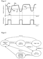
- FIG. 2 shows in the upper part an exemplary time profile of the sensor signal during several target cycles and in the lower part an associated time profile of the switching signal.
- the switching signal is produced by evaluating the sensor signal with the threshold 22, which ultimately results in a 1-bit-valued digitization or binarization means.
- the sensor signal remains as in FIG. 2 to be recognized at an upper constant value, which is referred to as absence level 24a in the context of this description.
- absence level 24a in the context of this description.
- the target object 20 is only at a distance from the proximity sensor 10, which corresponds at most to the switching distance 16. While the target object 20 remains at this distance, the sensor signal forms the FIG. 2 another constant range, which is referred to as presence level 24c in the context of this description. If the target object 20 subsequently as in Figure 1d removed again, the sensor signal returns FIG. 2 via a rising edge 24d back to the absence level 24a, and it closes after a certain pause the next target cycle.
- the movement of the target object 20 can, of course, also take place differently than shown, also transversely or with a transverse component.
- the description based on an inductive proximity sensor 10 is to be understood only as an example to which the invention is not limited.
- a corresponding behavior of the sensor signal also occurs with other electromagnetic proximity sensors, such as capacitive, magnetic or microwave sensors. However, it may then be the case that the sensor signal behaves exactly in the opposite direction, ie rises when the target object 20 approaches.
- the evaluation and the drift compensation according to the invention explained below can take this into account by means of a corresponding change of sign.
- the threshold 22 is adjusted.
- the evaluation unit 14 may analyze the temporal change of the sensor signal to determine when the target 20 is absent and has no influence on the sensor signal and when it is present.
- a possible goal of this evaluation is the situations of FIGS. 1a or 1c to determine the absence level 24a and / or the presence level 24c. For this analysis, it is necessary to consider the sensor signal changing with the distance of the target object 20, and not just the switching signal. In addition, the fact can be exploited that the drift effects affect the sensor signal almost identically regardless of the position of the target object 20.
- An absence or absence of the target object 20 can preferably be detected by an analysis of the derivative of the sensor signal.
- a target cycle that is, passing through the target object 20 through a detection range of the proximity sensor 10, as in FIG Figure 1a-d illustrates, generates a characteristic derivative pattern. Drift effects do not show this derivation pattern, but cause, for example, only a very small derivative (temperature), always have the same sign (wear, aging) or appear only as a single event (installation change).
- the initially constant derivative becomes negative for a target cycle, followed by a plateau with derivative zero and a positive derivative, which drops back to zero.
- the pattern of this sequence of signs of the derivative can be clearly detected and distinguished from changes caused by noise or drift.
- the evaluation unit 14 can assume that the target object 20 is absent at this moment and, accordingly, the absence level 24a is present.
- a rapid drift is superimposed on the rapid changes of the sensor signal due to the movement of the target object 20, for example due to temperature change.
- the derivative also deviates from zero by the drift, but this is certainly distinguished by the described recognition of the sequence of the signs.
- FIG. 3 illustrates a way to model the analysis of the derivative in a state machine and thereby allow easy evaluation.
- the states and conditions for state transitions are in FIG. 1 and 2 comprehensibly.
- the first state “waiting for target approach” is like in FIG. 1a no target 20 near the proximity sensor 10, and the sensor signal corresponds to the absence level 24a.
- the transition to a second state “Target is approaching” according to Figure 1 b takes place when the derivative becomes negative in the falling edge 24b of the sensor signal.
- the state machine enters a third state "Target is there" according to Figure 1c above. In this state, the presence level can be measured.
- the transition to a fourth state "target moves away” then takes place in accordance with Figure 1d .
- the second state there is no measurable phase in which the target object 20 is present, but it goes away immediately, omitting the third state, and so the second state goes directly to the fourth state for positive derivation.
- the presence level 24c can then be estimated as the minimum of the sensor signal.
- absence levels 24a and / or presence levels 24c may be stored.
- the return to the first state may also be due to cancellation due to time lapse (time out), this being done in FIG. 3 by way of example for the third and fourth states.
- the evaluation via a state machine or classifier is simple and robust. But there are also alternative evaluations conceivable, for example by neural networks.
- absence level 24a and / or presence level 24c allows the threshold 22 to be adapted to drift effects, as shown in FIG. 2 is exemplified at an adaptation point 22a.
- two preferred embodiments are presented in more detail below.
- the proximity sensor 10 should always switch in the same switching distance 16, despite the drifts.
- the proximity sensor 10 is mounted, for example, at room temperature under certain installation conditions and has at this moment a user-acceptable switching interval 16.
- the evaluation unit 14 determines now initially and repeatedly, for example cyclically at fixed intervals or after each fully recognized target run, the absence level 24a. If this value has changed from the previously stored value, the threshold 22 is modified by the difference between the old value and the new value. At least the last value used for a threshold adjustment or the initial value is stored for later threshold adjustments.
- the threshold 22 may, but does not have to be, changed directly by the difference in the absence levels 24a, but may also take into account a scaling factor or nonlinearities.
- the proximity sensor 10 does not have a fixed switching distance 16, but always adapts the switching distance 16 so that the presence of a target object 20 with the greatest possible immunity to interference is detected.
- the threshold 22 is not only tracked, but redefined on the basis of the absence level 24a and the presence level 24c.
- An exemplary Robust threshold is achieved by placing the threshold 22 at the middle between the absence level 24a and the presence level 24c.
- the proximity sensor 10 has the goal of robust detection as possible and waives a fixed switching distance 16.
- the proximity sensor 10 determines itself a switching distance 16, so to speak itself. This has the advantage that installation influences are automatically eliminated immediately after commissioning and also the material of the target object 20 for a secure detection does not matter.
- Such proximity sensors 10 also need to be designed only for a maximum possible and not a fixed switching distance 16. All switching distances smaller than the maximum possible are covered by one and the same device. As a result, the variance, logistics and procurement costs are considerably reduced both by the manufacturer and by the user of the proximity sensor 10.
Landscapes
- Physics & Mathematics (AREA)
- General Physics & Mathematics (AREA)
- Electronic Switches (AREA)
- Geophysics And Detection Of Objects (AREA)
Abstract
Es wird ein elektromagnetischer Näherungssensor (10) zur Erfassung eines Zielobjekts (20) angegeben, der ein Sensorelement (12) zur Erzeugung eines Sensorsignals, das sich mit dem Abstand des Zielobjekts (20) verändert, und eine Auswertungseinheit (14) aufweist, in der durch Vergleich des Sensorsignals mit einer Schaltschwelle (22) die Anwesenheit des Zielobjekts (20) in einem Schaltabstand (16) erkennbar ist. Dabei ist die Auswertungseinheit (14) dafür ausgebildet, einen Abwesenheitspegel (24a) des Sensorsignals, während kein Zielobjekt (20) das Sensorsignal beeinflusst, und/oder einen Anwesenheitspegel (24c) des Sensorsignals zu erfassen, während ein Zielobjekt (20) als anwesend erkannt ist, und die Schaltschwelle (22) anhand des Abwesenheitspegels (24a) und/oder des Anwesenheitspegels (24c) anzupassen.The invention relates to an electromagnetic proximity sensor (10) for detecting a target object (20) which has a sensor element (12) for generating a sensor signal which varies with the distance of the target object (20) and an evaluation unit (14) by comparing the sensor signal with a switching threshold (22) the presence of the target object (20) in a switching distance (16) can be seen. In this case, the evaluation unit (14) is designed to detect an absence level (24a) of the sensor signal, while no target object (20) influences the sensor signal, and / or to detect a presence level (24c) of the sensor signal, while a target object (20) is recognized as present is, and the switching threshold (22) on the basis of the absence level (24a) and / or the presence level (24c) adapt.
Description
Die Erfindung betrifft einen elektromagnetischen Näherungssensor und ein Verfahren zur Erfassung eines Zielobjekts nach dem Oberbegriff von Anspruch 1 beziehungsweise 10.The invention relates to an electromagnetic proximity sensor and to a method for detecting a target object according to the preamble of
Näherungssensoren erkennen die Anwesenheit oder Annäherung von Objekten bei einem Schaltabstand. Das Objekt wird in diesem Zusammenhang häufig als Target oder Ziel bezeichnet. Je nach Technologie werden Ziele mit bestimmten Eigenschaften erkannt. Beispielsweise erkennt ein induktiver Näherungssensor leitende, in der Praxis vor allem metallische Ziele, während ein kapazitiver Näherungssensor auf dielektrische Eigenschaften reagiert. Näherungssensoren werden sehr oft als berührungslose Schalter eingesetzt, mit einem Schaltzustand bei Anwesenheit und dem anderen Schaltzustand bei Abwesenheit eines Ziels im Schaltabstand.Proximity sensors detect the presence or approach of objects at a sensing distance. The object is often referred to as a target or target in this context. Depending on the technology, goals with certain characteristics are recognized. For example, an inductive proximity sensor recognizes conductive, in practice primarily metallic targets, while a capacitive proximity sensor responds to dielectric properties. Proximity sensors are very often used as non-contact switches, with a switching state in the presence and the other switching state in the absence of a target in the switching distance.
Die Näherungssensoren sind dabei häufig einer rauen Umgebung mit hohen Temperaturschwankungen, Verschmutzung und Verschleiß vor allem des zu detektierenden Objekts durch mechanische Beanspruchung ausgesetzt, was auch noch Alterungserscheinungen des Sensors verstärkt. Solche Effekte werden zusammenfassend als Driften bezeichnet. Ein weiteres Problem stellen die sogenannten Einbaubedingungen dar. Ein induktiver Sensor reagiert auf alle metallischen Objekte in seiner Nähe, nicht nur auf das zu erfassende Objekt. Ein kapazitiver Sensor wird auch durch die dielektrischen Eigenschaften der Umgebung beeinflusst. Ähnliche Effekte gibt es auch bei magnetischen Sensoren oder Mikrowellensensoren. Deshalb verändert sich der Schaltabstand unter Umständen in einer neuen Umgebung oder aufgrund von Driften sehr stark, der als Schalter eingesetzte Sensor geht also in der Praxis nicht mehr aus oder schaltet nicht mehr ein. Das Problem verstärkt sich bei großen Schaltabständen, weil dann die Empfindlichkeit der Sensoren zunimmt.The proximity sensors are often exposed to a harsh environment with high temperature fluctuations, pollution and wear especially of the object to be detected by mechanical stress, which also amplifies aging phenomena of the sensor. Such effects are referred to collectively as drifts. Another problem is the so-called installation conditions. An inductive sensor reacts to all metallic objects in its vicinity, not just to the object to be detected. A capacitive sensor is also affected by the dielectric properties of the environment. Similar effects also exist with magnetic sensors or microwave sensors. Therefore, the switching distance changes under certain circumstances in a new environment or due to drift very strong, the sensor used as a switch is therefore no longer in practice or does not turn on anymore. The problem increases with large switching distances, because then the sensitivity of the sensors increases.
Herkömmliche Näherungssensoren haben einen festen Schaltabstand und stellen darüber hinaus keine Information über den Abstand des erfassten Objekts zur Verfügung. Von den Driften wird typischerweise nur die Temperatur berücksichtigt, und zwar in einer klassischen Temperaturkompensation durch Messung der Temperatur und Verwendung einer Korrekturtabelle. Das ist fehlerbehaftet, weil die Temperatur der Messelektronik nicht der Temperatur des eigentlichen Sensorelements entspricht, beispielsweise der Sensorspule eines induktiven Sensors. Die übrigen genannten Effekte werden gar nicht kompensiert.Conventional proximity sensors have a fixed switching distance and moreover provide no information about the distance of the detected object. Of the drifts, typically only the temperature is taken into account, in a classical temperature compensation by measuring the temperature and using a correction table. This is faulty because the temperature of the measuring electronics does not correspond to the temperature of the actual sensor element, for example the sensor coil of an inductive sensor. The other mentioned effects are not compensated at all.
Für optische Sensoren ist aus der
Es ist daher Aufgabe der Erfindung, das Schaltverhalten eines elektromagnetischen Näherungssensors robuster zu machen.It is therefore an object of the invention to make the switching behavior of an electromagnetic proximity sensor more robust.
Diese Aufgabe wird durch einen elektromagnetischen Näherungssensor und ein Verfahren zur Erfassung eines Zielobjekts nach Anspruch 1 beziehungsweise 10 gelöst. Ein elektromagnetischer Näherungssensor erzeugt mit einem Sensorelement ein vom Abstand eines Zielobjekts abhängiges Sensorsignal und wertet dies mit einer Schaltschwelle aus, um Anwesenheit des Zielobjekts in einem Schaltabstand festzustellen. Die Erfindung geht nun von dem Grundgedanken aus, die Schaltschwelle an einen sich durch Driften verändernden Pegel des Sensorsignals anzupassen. Dazu wird ein Anwesenheitspegel gemessen, während das Zielobjekt als anwesend erkannt ist, beziehungsweise ein Abwesenheitspegel, wenn kein Zielobjekt das Sensorsignal beeinflusst. Änderungen von Anwesenheits- oder Abwesenheitspegel sind dann nicht dem Abstand des Zielobjekts, sondern den Driften geschuldet, und dementsprechend können die Driften durch Anpassung der Schaltschwelle kompensiert werden. Es ist zu beachten, dass die für die Kompensation erkannte Anwesenheit und Abwesenheit nicht gleichzusetzen ist mit den beiden Schaltzuständen. Beispielsweise beeinflusst ein Objekt in etwas größerer Entfernung als der Schaltabstand durchaus noch das Sensorsignal, d. h. es ist noch anwesend im Sinne der Driftkompensation, nicht aber im Sinne des Schaltzustands.This object is achieved by an electromagnetic proximity sensor and a method for detecting a target object according to
Die Erfindung hat den Vorteil, dass ein ungewolltes Verschieben des Schaltabstands und insbesondere ein Funktionsausfall verhindert wird. Der Sensor bleibt dadurch auch in rauen Umgebungen zuverlässig einsatzfähig. Es wird eine Kompensation von Driften wie Verschleiß- und Alterungserscheinungen an dem Sensor oder dessen Halterung, Verschmutzung oder Temperaturschwankungen und eine Anpassung an Abweichungen vom Normeinbau beziehungsweise Änderungen der Einbauumgebung insbesondere während der Laufzeit ermöglicht.The invention has the advantage that an unintentional shifting of the switching distance and in particular a functional failure is prevented. The sensor remains reliably operational even in harsh environments. It is possible to compensate for drifts such as wear and aging phenomena on the sensor or its holder, contamination or temperature fluctuations, and adaptation to deviations from normal installation or changes in the installation environment, in particular during runtime.
Vorzugsweise umfasst das Sensorelement eine Sendespule mit einer Erregerschaltung und eine Empfangsspule, wobei das Sensorsignal aus der Spannung über der Empfangsspule abgeleitet ist, oder das Sensorelement weist einen Schwingkreis mit einer Spule auf, wobei das Sensorsignal aus der Spannung über dem Schwingkreis abgeleitet ist. Dies sind bewährte Arbeitsprinzipien eines induktiven Näherungsschalters. Die Spannung in der Empfangsspule beziehungsweise in dem Schwingkreis sinkt durch in einem Zielobjekt induzierte Wirbelströme ab, wobei dieser Effekt sich mit zunehmender Nähe des Zielobjekts erhöht.Preferably, the sensor element comprises a transmitting coil with an excitation circuit and a receiving coil, wherein the sensor signal is derived from the voltage across the receiving coil, or the sensor element comprises a resonant circuit with a coil, wherein the sensor signal is derived from the voltage across the resonant circuit. These are proven working principles of an inductive proximity switch. The voltage in the receiver coil or in the resonant circuit decreases due to eddy currents induced in a target object, this effect increasing with increasing proximity of the target object.
Die Auswertungseinheit ist bevorzugt dafür ausgebildet, die Schaltschwelle entsprechend den Änderungen des Abwesenheitspegels anzupassen. Die Schaltschwelle wird also entsprechend einer Drift des Abwesenheitspegels nachgeführt. Dadurch bleibt der Schaltabstand trotz Driften konstant. Dieses Vorgehen wird auch als Autokorrektur bezeichnet. Einflüsse der Driften auf den Schaltabstand des Sensors sind eliminiert, und dadurch erhöht sich die Verfügbarkeit und Robustheit der Erfassung enorm.The evaluation unit is preferably designed to adapt the switching threshold in accordance with the changes in the absence level. The switching threshold is thus tracked according to a drift of the absence level. As a result, the switching distance remains constant despite drifting. This procedure is also called autocorrection. Influences of the drifts on the switching distance of the sensor are eliminated, and thus the availability and robustness of the detection increases enormously.
In einer alternativen vorteilhaften Ausführungsform ist die Auswertungseinheit dafür ausgebildet, die Schaltschwelle bei einer Anpassung mit großem Störabstand zu Abwesenheitspegel und Anwesenheitspegel neu festzulegen, insbesondere auf deren Mittelwert. Hierbei geht es nicht darum, den Schaltabstand konstant zu halten, sondern der Sensor setzt seine Schaltschwelle und damit seinen Schaltabstand so fest, dass ein besonders robustes Schaltverhalten sichergestellt ist, das eine maximale Störunempfindlichkeit erlaubt. Dieses Vorgehen wird auch als Autodetektion bezeichnet. Ein solcher Sensor hat keinen festen Schaltabstand mehr, und damit muss der Schaltabstand auch nicht mehr eingestellt werden. Der Sensor besitzt lediglich noch einen maximal möglichen Erfassungsbereich. Dadurch verringert sich die Varianz der Sensormodelle erheblich, mit entsprechenden Kostenvorteilen bei Hersteller und Kunde.In an alternative advantageous embodiment, the evaluation unit is designed to redetermine the switching threshold in an adaptation with high S / N ratio to absence level and presence level, in particular to their Average. This is not about keeping the switching distance constant, but the sensor sets its switching threshold and thus its switching distance so tightly that a particularly robust switching behavior is ensured, which allows maximum immunity to interference. This procedure is also called autodetection. Such a sensor has no fixed switching distance more, and thus the switching distance must not be adjusted. The sensor only has a maximum possible detection range. This significantly reduces the variance of the sensor models, with corresponding cost advantages for the manufacturer and the customer.
Die Auswertungseinheit ist bevorzugt dafür ausgebildet, einen zeitlichen Verlauf des Sensorsignals mit einem Referenzverlauf während einer erwarteten Bewegung des Zielobjekts zu vergleichen und so Zeitpunkte zur Erfassung des Abwesenheitspegels und/oder des Anwesenheitspegels zu bestimmen. In wichtigen Anwendungen wiederholt sich die Annäherungsbewegung des Zielobjekts zyklisch. Auch sonst können typische Annäherungsszenarien bekannt sein und eingelernt werden. Der Sensor erkennt durch Vergleich mit einem solchen Referenzverlauf, welche Veränderungen des Sensorsignals auf die Bewegung des Zielobjekts zurückzuführen sind. Deshalb ist der Sensor in der Lage, Zeitpunkte zu bestimmen, in denen das Zielobjekt anwesend oder abwesend ist, um die entsprechenden Pegel für die Schwellenanpassung zu bestimmen.The evaluation unit is preferably designed to compare a time profile of the sensor signal with a reference curve during an expected movement of the target object and thus to determine times for detecting the absence level and / or the presence level. In important applications, the approaching motion of the target object is repeated cyclically. Even otherwise, typical approach scenarios can be known and learned. The sensor recognizes by comparison with such a reference curve, which changes of the sensor signal are due to the movement of the target object. Therefore, the sensor is able to determine times at which the target is present or absent to determine the appropriate levels for threshold adjustment.
Die Auswertungseinheit ist bevorzugt dafür ausgebildet, Zeitpunkte zur Erfassung des Abwesenheitspegels und/oder des Anwesenheitspegels anhand einer Untersuchung der Ableitung des Sensorsignals zu bestimmen. Driften haben einen signifikant anderen Einfluss auf die Ableitung des Sensorsignals als die Bewegung des Zielobjekts. Generell sind Driften langsamer und stets gleichgerichtet wie bei Verschleiß, Alterung oder Verschmutzung, oder sie sind Einmaleffekte wie bei einem Umbau. Deshalb ermöglicht eine Betrachtung der Ableitung die Festlegung von Zeitpunkten zur Bestimmung des Abwesenheits- oder Abwesenheitspegels und verhindert insbesondere, diese Pegel gerade während einer Bewegung des Zielobjekts zu bestimmen und so die Schwelle fälschlich gemäß einer weitgehend zufälligen Position des Zielobjekts statt einer Drift anzupassen.The evaluation unit is preferably designed to determine times for detecting the absence level and / or the presence level on the basis of an examination of the derivative of the sensor signal. Drifts have a significantly different effect on the derivative of the sensor signal than the movement of the target. In general, drifts are slower and always rectified as in wear, aging or contamination, or they are one-off effects as in a conversion. Therefore, consideration of the derivative allows determination of times to determine the absence or absence level and, in particular, prevents these levels from being determined during movement of the target object and thus mistakenly adjusting the threshold according to a largely random position of the target instead of drifting.
Die Auswertungseinheit ist bevorzugt dafür ausgebildet, das Sensorsignals auf eine erwartete zeitliche Abfolge des Vorzeichens der Ableitung zu untersuchen. Dabei müssen keine Modelle für den quantitativen Verlauf der Ableitung aufgestellt und mit schwer festzulegenden Toleranzen überprüft werden, sondern es wird lediglich eine einfache Abfolge des sehr robust bestimmbaren Vorzeichens der Ableitung überwacht. Ein Beispiel für eine Abfolge ist eine zunächst negative Ableitung, die dann direkt oder mit einem Plateau bei Ableitung Null in eine positive Ableitung übergeht und wieder auf Null abfällt. Das entspricht dann einem Targetzyklus eines sich nähernden und wieder entfernenden Zielobjekts. Wie aus dem Beispiel hervorgeht, soll der Wert Null mit samt einer gewissen Toleranzumgebung auch als ein Vorzeichen der Ableitung aufgefasst werden. Ob die Ableitung positiv oder negativ ist, hängt auch vom Sensorprinzip ab. Es wird dabei immer von einem Sensor ausgegangen, bei dem das Sensorsignal wie bei einem induktiven Sensor mit zunehmender Nähe des Zielobjekts geschwächt wird. Bei anderen Sensoren mit höherem Pegel bei nahen Zielobjekten sind die Vorzeichen entsprechend umzukehren.The evaluation unit is preferably designed to examine the sensor signal for an expected time sequence of the sign of the derivative. There are no models for the quantitative course of the derivative set up and with difficult to be determined tolerances are checked, but it is only monitored a simple sequence of very robust determinable sign of the derivative. An example of a sequence is an initially negative derivative, which then goes directly or with a plateau at zero derivative into a positive derivative and drops back to zero. This then corresponds to a target cycle of an approaching and departing target object. As can be seen from the example, the value zero, together with a certain tolerance environment, should also be understood as a sign of the derivative. Whether the derivative is positive or negative also depends on the sensor principle. It is always assumed that a sensor in which the sensor signal is weakened as with an inductive sensor with increasing proximity of the target. For other higher-level sensors on nearby targets, the signs should be reversed accordingly.
Die Auswertungseinheit ist bevorzugt dafür ausgebildet, aus dem Vorzeichen der Ableitung des Sensorsignals Bedingungen für einen Zustandsübergang in einem Zustandsautomaten abzuleiten, wobei in einem ersten Zustand der Abwesenheitspegel und/oder in einem weiteren Zustand der Anwesenheitspegel bestimmt wird. Ein Targetzyklus eines Annäherns und anschließenden Sich-Entfernens eines Zielobjekts wird hierbei als Zustandsautomat beziehungsweise Klassifikator modelliert, wobei das Vorzeichen der Ableitung die Bedingung für einen Zustandsübergang oder Klassenwechsel festlegt. Ein solcher Zustandsautomat ist sehr einfach implementierbar und ermöglicht eine robuste Bestimmung von Zuständen beziehungsweise Zeitpunkten, in denen die für die Anpassung der Schwelle benötigten Abwesenheits- oder Anwesenheitspegel ermittelt werden.The evaluation unit is preferably designed to derive conditions for a state transition in a state machine from the sign of the derivative of the sensor signal, the absence level and / or the presence level being determined in a further state in a first state. A target cycle of approaching and subsequently removing a target object is hereby modeled as a state machine or classifier, the sign of the derivation determining the condition for a state transition or class change. Such a state machine is very easy to implement and enables a robust determination of states or times in which the absence or presence levels required for the adaptation of the threshold are determined.
Der Zustandsautomat weist bevorzugt den ersten Zustand "Warten auf Targetannäherung", den zweiten Zustand "Target nähert sich", einen dritten Zustand "Target ist da" und einen vierten Zustand "Target entfernt sich" auf, mit den Zustandsübergängen
- erster Zustand auf dritter Zustand bei negativer Ableitung
- zweiter Zustand auf dritten Zustand bei Ableitung Null
- zweiter Zustand auf vierten Zustand bei positiver Ableitung
- dritter Zustand auf vierten Zustand bei positiver Ableitung und
- vierter Zustand auf ersten Zustand bei Ableitung Null.
- first state to third state with negative derivative
- second state to third state at zero derivation
- second state to fourth state with positive derivative
- third state to fourth state with positive derivative and
- fourth state to first state at zero derivative.
Dies ist ein einfacher Zustandsautomat, der dennoch die typische Erfassungssituation an einem Näherungssensor beschreibt und damit eine robuste Schwellenanpassung ermöglicht. Der Anwesenheitspegel kann im dritten Zustand gemessen werden. Es ist alternativ auch denkbar, den Anwesenheitspegel als Maximum beim Übergang vom zweiten Zustand auf den vierten Zustand zu bestimmen. Dabei kann in einigen Ausführungsformen sogar auf den dritten Zustand und die zugehörigen Bedingungen für einen Zustandsübergang verzichtet werden.This is a simple state machine that still describes the typical detection situation on a proximity sensor and thus a robust threshold adjustment allows. The presence level can be measured in the third state. Alternatively, it is also conceivable to determine the presence level as a maximum during the transition from the second state to the fourth state. In some embodiments, even the third state and the associated conditions for a state transition can be dispensed with.
Das erfindungsgemäße Verfahren kann auf ähnliche Weise weitergebildet werden und zeigt dabei ähnliche Vorteile. Derartige vorteilhafte Merkmale sind beispielhaft, aber nicht abschließend in den sich an die unabhängigen Ansprüche anschließenden Unteransprüchen beschrieben.The method according to the invention can be developed in a similar manner and shows similar advantages. Such advantageous features are described by way of example but not exhaustively in the subclaims following the independent claims.
Die Erfindung wird nachstehend auch hinsichtlich weiterer Merkmale und Vorteile beispielhaft anhand von Ausführungsformen und unter Bezug auf die beigefügte Zeichnung näher erläutert. Die Abbildungen der Zeichnung zeigen in:
- Fig.1a-d
- schematische Darstellungen eines Näherungssensors über einen Targetzyklus eines sich annähernden und wieder entfernenden Zielobjekts;
- Fig. 2
- beispielhafte zeitliche Verläufe eines Sensorsignals und eines daraus mit einer Schwelle abgeleiteten Schaltsignals über mehrere Targetzyklen; und
- Fig. 3
- ein beispielhaftes Zustandsdiagramm für die Erkennung eines Targetzyklus' auf Basis einer Ableitungsanalyse.
- 1a-d
- schematic representations of a proximity sensor over a target cycle of an approaching and removing target object;
- Fig. 2
- exemplary time profiles of a sensor signal and a derived therefrom with a threshold switching signal over several target cycles; and
- Fig. 3
- an exemplary state diagram for the detection of a target cycle on the basis of a derivative analysis.
Das Arbeitsprinzip eines induktiven Näherungssensors 10 ist an sich bekannt und wird daher nicht im Detail erläutert. Ein gängiges Prinzip ist, in dem Sensorelement 12 eine Sendespule und eine Empfangsspule unterzubringen. Eine an die Sendespule angeschlossene Erregerschaltung baut in der Sendespule ein Wechselfeld auf, welches wiederum in der Empfangsspule eine Spannung induziert. Die Auswertungseinheit 14 nutzt die Spannungsamplitude als Sensorsignal. Es gibt viele Alternativen, einen induktiven Sensor mit einer anderen Anzahl und Anordnung von Spulen aufzubauen. Beispielsweise ist ein weiteres bewährtes Prinzip das Vorsehen nur eines Schwingkreises mit einer Spule, wobei dann die Spannung über diesem Schwingkreis das Sensorsignal bildet.The working principle of an
Die
Solange sich wie in
In
Die Bewegung des Zielobjekts 20 kann selbstverständlich anders als dargestellt auch transversal oder mit transversaler Komponente erfolgen. Auch die Beschreibung anhand eines induktiven Näherungssensors 10 soll nur als Beispiel verstanden werden, auf das die Erfindung nicht beschränkt ist. Ein entsprechendes Verhalten des Sensorsignals ergibt sich auch bei anderen elektromagnetischen Näherungssensoren, wie kapazitiven, magnetischen oder Mikrowellensensoren. Allerdings kann es dann sein, dass das Sensorsignal sich gerade umgekehrt verhält, nämlich bei Annäherung des Zielobjekts 20 ansteigt. Die Auswertung und die im Folgenden erläuterte erfindungsgemäße Driftkompensation kann dies durch entsprechende Vorzeichenwechsel berücksichtigen.The movement of the
Wie einleitend erläutert, ergibt sich ein Problem der Schwellbewertung dadurch, dass die Veränderungen des Sensorsignals durch Annäherung des Zielobjekts 20 von Störoder Drifteffekten überlagert sind, was zu Verschiebungen des Schaltabstands 16 und im Extremfall einem Funktionsausfall führt. Erfindungsgemäß wird deshalb die Schwelle 22 angepasst.As explained in the introduction, a problem of the threshold evaluation results from the fact that the changes in the sensor signal are superimposed by disturbing the
Es ist aber möglich, den Einfluss von Driften und Bewegungen des Zielobjekts 20 auf das Sensorsignal zu trennen. Ein Lösungsansatz besteht darin, dass die Driften wesentlich langsamer, wie im Falle von Verschleiß, Alterung, Verschmutzung oder Temperaturänderung, oder wesentlich seltener sind als die Bewegungen des Zielobjekts 20, wie im Falle einer veränderten Einbausituation. Die Auswertungseinheit 14 kann die zeitliche Veränderung des Sensorsignals analysieren, um festzustellen, wann das Zielobjekt 20 abwesend ist und keinen Einfluss auf das Sensorsignal ausübt und wann es anwesend ist. Ein mögliches Ziel dieser Auswertung ist, die Situationen der
Eine Abwesenheit beziehungsweise Abwesenheit des Zielobjekts 20 kann vorzugsweise durch eine Analyse der Ableitung des Sensorsignals erkannt werden. Ein Targetzyklus, also ein Durchlaufen des Zielobjekts 20 durch einen Erfassungsbereich des Näherungssensors 10 wie in
Wie anhand
Wenn dann im vierten Zustand die Ableitung erneut verschwindet, ist der Targetzyklus beendet, und der Zustandsautomat kehrt in den ersten Zustand zurück. Zuvor können je nach Bedarf Abwesenheitspegel 24a und/oder Anwesenheitspegel 24c gespeichert werden. Die Rückkehr in den ersten Zustand kann auch durch Abbruch wegen Zeitablauf (time out) erfolgen, wobei dies in
Die Auswertung über einen Zustandsautomaten oder Klassifikator ist einfach und robust. Es sind aber auch alternative Auswertungen beispielsweise durch neuronale Netze denkbar.The evaluation via a state machine or classifier is simple and robust. But there are also alternative evaluations conceivable, for example by neural networks.
Die Kenntnis von Abwesenheitspegel 24a und/oder Anwesenheitspegel 24c ermöglicht eine Anpassung der Schwelle 22 an Drifteffekte, wie dies in
In einem Autokorrekturverfahren (Auto-Correct) soll der Näherungssensor 10 trotz der Driften immer im gleichen Schaltabstand 16 schalten. Dazu wird der Näherungssensor 10 beispielsweise bei Raumtemperatur unter bestimmten Einbaubedingungen montiert und hat in diesem Moment einen für den Anwender akzeptablen Schaltabstand 16. Die Auswertungseinheit 14 bestimmt nun anfänglich und immer wieder, beispielsweise zyklisch in festen Zeitabständen oder nach jedem als vollständig erkannten Targetdurchlauf, den Abwesenheitspegel 24a. Wenn sich dieser Wert gegenüber dem zuvor gespeicherten Wert verändert hat, wird die Schwelle 22 um die Differenz zwischen altem Wert und neuem Wert modifiziert. Zumindest der zuletzt für eine Schwellenanpassung verwendete, beziehungsweise der anfängliche Wert wird für spätere Schwellenanpassungen gespeichert. Die Schwelle 22 kann, muss aber nicht direkt um die jeweilige Differenz der Abwesenheitspegel 24a verändert werden, sondern kann auch noch einen Skalierungsfaktor oder Nichtlinearitäten berücksichtigen.In an auto-correction method (Auto-Correct), the
Mit dem Autokorrekturverfahren wird der Einfluss von Drifteffekten auf die Schaltschwelle nahezu eliminiert, und der Schaltabstand 16 bleibt über die Lebensdauer stets auf dem anfänglich beispielsweise während der Installation eingestellten Wert.With the auto-correction method, the influence of drift effects on the switching threshold is almost eliminated, and the
In einem alternativen Autodetektionsverfahren (Auto-Detect) hat der Näherungssensor 10 keinen festen Schaltabstand 16, sondern passt den Schaltabstand 16 immer so an, dass die Anwesenheit eines Zielobjekts 20 mit möglichst großer Störunempfindlichkeit erkannt wird. Dabei wird die Schwelle 22 nicht nur nachgeführt, sondern anhand des Abwesenheitspegels 24a und des Anwesenheitspegels 24c neu festgelegt. Eine beispielhafte robuste Schwellenlage wird dadurch erreicht, dass die Schwelle 22 auf die Mitte zwischen Abwesenheitspegel 24a und Anwesenheitspegel 24c gelegt wird.In an alternative auto-detection method, the
Der Näherungssensor 10 hat beim Autodetektionsverfahren das Ziel einer möglichst robusten Erkennung und verzichtet dafür auf einen festgelegten Schaltabstand 16. Der Näherungssensor 10 ermittelt sich einen Schaltabstand 16 sozusagen selbst. Dies hat den Vorteil, dass Einbaueinflüsse direkt nach der Inbetriebnahme automatisch eliminiert werden und auch das Material des Zielobjekts 20 für eine sichere Erkennung keine Rolle spielt. Solche Näherungssensoren 10 brauchen auch nur für einen maximal möglichen und nicht einen festen Schaltabstand 16 ausgelegt werden. Alle Schaltabstände kleiner dem maximal möglichen werden durch ein und dasselbe Gerät mit abgedeckt. Dadurch werden Varianz, Logistik- und Beschaffungsaufwand sowohl beim Hersteller als auch beim Anwender des Näherungssensors 10 erheblich verringert.The
Claims (10)
dadurch gekennzeichnet,
dass die Auswertungseinheit (14) dafür ausgebildet ist, einen Abwesenheitspegel (24a) des Sensorsignals, während kein Zielobjekt (20) das Sensorsignal beeinflusst, und/oder einen Anwesenheitspegel (24c) des Sensorsignals zu erfassen, während ein Zielobjekt (20) als anwesend erkannt ist, und die Schaltschwelle (22) anhand des Abwesenheitspegels (24a) und/oder des Anwesenheitspegels (24c) anzupassen.Electromagnetic proximity sensor (10), in particular inductive proximity sensor, for detecting a target object (20) which has a sensor element (12) for generating a sensor signal which varies with the distance of the target object (20) and an evaluation unit (14) in that the presence of the target object (20) can be recognized by comparing the sensor signal with a switching threshold (22) at a switching distance (16),
characterized,
in that the evaluation unit (14) is designed to detect an absence level (24a) of the sensor signal, while no target object (20) influences the sensor signal, and / or a presence level (24c) of the sensor signal, while recognizing a target object (20) as being present is, and the switching threshold (22) on the basis of the absence level (24a) and / or the presence level (24c) adapt.
wobei das Sensorelement (12) eine Sendespule mit einer Erregerschaltung und eine Empfangsspule umfasst und das Sensorsignal aus der Spannung über der Empfangsspule abgeleitet ist, oder wobei das Sensorelement (12) einen Schwingkreis mit einer Spule aufweist und das Sensorsignal aus der Spannung über dem Schwingkreis abgeleitet ist.Proximity sensor (10) according to claim 1,
wherein the sensor element (12) comprises a transmitting coil with an excitation circuit and a receiving coil and the sensor signal is derived from the voltage across the receiving coil, or wherein the sensor element (12) comprises a resonant circuit with a coil and the sensor signal derived from the voltage across the resonant circuit is.
wobei die Auswertungseinheit (14) dafür ausgebildet ist, die Schaltschwelle (22) entsprechend den Änderungen des Abwesenheitspegels (24a) anzupassen.Proximity sensor (10) according to claim 1 or 2,
wherein the evaluation unit (14) is adapted to adjust the switching threshold (22) in accordance with the changes in the absence level (24a).
wobei die Auswertungseinheit (14) dafür ausgebildet ist, die Schaltschwelle (22) bei einer Anpassung mit großem Störabstand zu Abwesenheitspegel (24a) und Anwesenheitspegel (24b) neu festzulegen, insbesondere auf deren Mittelwert.Proximity sensor (10) according to claim 1 or 2,
wherein the evaluation unit (14) is adapted to newly set the switching threshold (22) in an adjustment with high S / N ratio to absence level (24a) and presence level (24b), in particular to their average value.
wobei die Auswertungseinheit (14) dafür ausgebildet ist, einen zeitlichen Verlauf des Sensorsignals mit einem Referenzverlauf während einer erwarteten Bewegung des Zielobjekts (20) zu vergleichen und so Zeitpunkte zur Erfassung des Abwesenheitspegels (24a) und/oder des Anwesenheitspegels (24c) zu bestimmen.Proximity sensor (10) according to one of the preceding claims,
wherein the evaluation unit (14) is adapted to a temporal course of the sensor signal with a reference curve during an expected movement of the target object (20) to compare and thus to determine times for detecting the absence level (24a) and / or the presence level (24c).
wobei die Auswertungseinheit (14) dafür ausgebildet ist, Zeitpunkte zur Erfassung des Abwesenheitspegels (24a) und/oder des Anwesenheitspegels (24c) anhand einer Untersuchung der Ableitung des Sensorsignals zu bestimmen.Proximity sensor (10) according to one of the preceding claims,
wherein the evaluation unit (14) is adapted to determine times for detecting the absence level (24a) and / or the presence level (24c) based on an investigation of the derivative of the sensor signal.
wobei die Auswertungseinheit (14) dafür ausgebildet ist, das Sensorsignal auf eine erwartete zeitliche Abfolge des Vorzeichens der Ableitung zu untersuchen.Proximity sensor (10) according to claim 6,
wherein the evaluation unit (14) is adapted to examine the sensor signal for an expected time sequence of the sign of the derivative.
wobei die Auswertungseinheit (14) dafür ausgebildet ist, aus dem Vorzeichen der Ableitung des Sensorsignals Bedingungen für einen Zustandsübergang in einem Zustandsautomaten abzuleiten, wobei in einem ersten Zustand der Abwesenheitspegel (24a) und/oder in einem weiteren Zustand der Anwesenheitspegel (24c) bestimmt wird.Proximity sensor (10) according to claim 6 or 7,
wherein the evaluation unit (14) is adapted to derive conditions for a state transition in a state machine from the sign of the derivative of the sensor signal, wherein in a first state the absence level (24a) and / or in a further state of the presence level (24c) is determined ,
wobei der Zustandsautomat den ersten Zustand "Warten auf Targetannäherung", den zweiten Zustand "Target nähert sich", einen dritten Zustand "Target ist da" und einen vierten Zustand "Target entfernt sich" aufweist, mit den Zustandsübergängen
the state machine having the first state "waiting for target approach", the second state "target approaching", a third state "target is there" and a fourth state "target is away" having the state transitions
dadurch gekennzeichnet,
dass ein Abwesenheitspegel (24a) des Sensorsignals, während kein Zielobjekt (20) das Sensorsignal beeinflusst, und/oder ein Anwesenheitspegel (24c) des Sensorsignals erfasst wird, während ein Zielobjekt (20) als anwesend erkannt ist, und die Schaltschwelle (22) anhand des Abwesenheitspegels (24a) und/oder des Anwesenheitspegels (24c) angepasst wird.A method for detecting a target object (20), in which the presence of the target object (20) in one of a sensor signal that varies with the distance of the target object (20) by comparison with a switching threshold (22) Switching distance (16) is detected,
characterized,
in that an absence level (24a) of the sensor signal, while no target object (20) influences the sensor signal, and / or a presence level (24c) of the sensor signal is detected while a target object (20) is detected as present, and the switching threshold (22) is based on the absence level (24a) and / or the presence level (24c) is adjusted.
Applications Claiming Priority (1)
| Application Number | Priority Date | Filing Date | Title |
|---|---|---|---|
| DE102015107221.1A DE102015107221B4 (en) | 2015-05-08 | 2015-05-08 | Electromagnetic proximity sensor and method for detecting a target |
Publications (3)
| Publication Number | Publication Date |
|---|---|
| EP3091663A2 true EP3091663A2 (en) | 2016-11-09 |
| EP3091663A3 EP3091663A3 (en) | 2017-01-04 |
| EP3091663B1 EP3091663B1 (en) | 2017-09-20 |
Family
ID=55752186
Family Applications (1)
| Application Number | Title | Priority Date | Filing Date |
|---|---|---|---|
| EP16164732.6A Active EP3091663B1 (en) | 2015-05-08 | 2016-04-11 | Electromagnetic proximity sensor and a method for detecting a target object |
Country Status (3)
| Country | Link |
|---|---|
| US (1) | US20160329892A1 (en) |
| EP (1) | EP3091663B1 (en) |
| DE (1) | DE102015107221B4 (en) |
Families Citing this family (5)
| Publication number | Priority date | Publication date | Assignee | Title |
|---|---|---|---|---|
| TWM552413U (en) * | 2016-02-25 | 2017-12-01 | 米沃奇電子工具公司 | Power tool including an output position sensor |
| DE102017118083B4 (en) | 2017-08-09 | 2022-11-24 | Sick Ag | Sensor for detecting an object and method for setting a switching point |
| JP6911672B2 (en) * | 2017-09-25 | 2021-07-28 | オムロン株式会社 | Proximity sensor manufacturing method and proximity sensor manufacturing system |
| DE102019121802B3 (en) * | 2019-08-13 | 2020-09-17 | Ifm Electronic Gmbh | Arrangement and method for setting a binary magnetic position sensor |
| DE102021114974A1 (en) | 2021-06-10 | 2022-12-15 | Infineon Technologies Ag | Devices and methods for position detection by a 3D magnetic field sensor |
Citations (1)
| Publication number | Priority date | Publication date | Assignee | Title |
|---|---|---|---|---|
| DE102011050119A1 (en) | 2011-05-05 | 2012-11-08 | Sick Ag | Optoelectronic sensor and method for object detection |
Family Cites Families (9)
| Publication number | Priority date | Publication date | Assignee | Title |
|---|---|---|---|---|
| DE19844663C2 (en) * | 1998-09-29 | 2000-09-21 | Siemens Ag | Circuit arrangement and method for setting switching points of a decision maker |
| US7132766B2 (en) * | 2003-03-25 | 2006-11-07 | Rockwell Automation Technologies, Inc. | Method and apparatus for providing a switching signal in the presence of noise |
| TW200949632A (en) * | 2008-05-22 | 2009-12-01 | Prospect Technology Corp | A trigger-threshold adaptable and auto-adjustable capacitive induction-type keying device |
| JP5584442B2 (en) * | 2009-08-26 | 2014-09-03 | パナソニック株式会社 | Object detection device and illumination system including the same |
| US8918209B2 (en) * | 2010-05-20 | 2014-12-23 | Irobot Corporation | Mobile human interface robot |
| FR2985034A1 (en) * | 2011-12-23 | 2013-06-28 | Continental Automotive France | METHOD FOR ADAPTING A SENSING THRESHOLD OF A CAMSHAFT SENSOR FOR A MOTOR VEHICLE |
| WO2014191379A1 (en) * | 2013-05-28 | 2014-12-04 | Inventio Ag | Elevator door with a door contact switch |
| BR112015032365A2 (en) * | 2013-08-19 | 2017-07-25 | Touchsensor Tech Llc | capacitive sensor filtration method |
| WO2015031009A2 (en) * | 2013-08-30 | 2015-03-05 | Allegro Microsystems, Llc | Circuits and methods for generating a threshold signal used in a motion detector in accordance with a least common multiple of a set of possible quantities of features upon a target |
-
2015
- 2015-05-08 DE DE102015107221.1A patent/DE102015107221B4/en not_active Expired - Fee Related
-
2016
- 2016-04-11 EP EP16164732.6A patent/EP3091663B1/en active Active
- 2016-04-29 US US15/141,944 patent/US20160329892A1/en not_active Abandoned
Patent Citations (1)
| Publication number | Priority date | Publication date | Assignee | Title |
|---|---|---|---|---|
| DE102011050119A1 (en) | 2011-05-05 | 2012-11-08 | Sick Ag | Optoelectronic sensor and method for object detection |
Also Published As
| Publication number | Publication date |
|---|---|
| US20160329892A1 (en) | 2016-11-10 |
| DE102015107221A1 (en) | 2016-11-10 |
| DE102015107221B4 (en) | 2018-04-12 |
| EP3091663A3 (en) | 2017-01-04 |
| EP3091663B1 (en) | 2017-09-20 |
Similar Documents
| Publication | Publication Date | Title |
|---|---|---|
| EP3091663B1 (en) | Electromagnetic proximity sensor and a method for detecting a target object | |
| EP3303955B1 (en) | Domestic appliance comprising a differential pressure sensor | |
| AT407983B (en) | DEVICE FOR DETECTING THE POSITIONS OF SWIVELABLE PARTS OF A SWITCH | |
| EP2169700B1 (en) | Method and device for monitoring a switching procedure and relay component group | |
| WO2012016868A1 (en) | Method and device for monitoring the surroundings of a vehicle | |
| WO2012140265A2 (en) | Apparatus and method for detecting electrically conductive items | |
| EP0783699B1 (en) | Active motion sensor | |
| EP0116850A1 (en) | Microprocessor controlled solenoid plunger print system containing an opto-electronic sensor | |
| EP3346177B1 (en) | Safety device | |
| EP1754021B1 (en) | Error correction method for a range sensor | |
| EP2884233B1 (en) | Measuring of parameters in an electromagnetic drive of a switching device | |
| DE102006005463A1 (en) | Optoelectronic device | |
| EP2112530A2 (en) | Method for detecting objects with a sensor | |
| DE102012012865A1 (en) | Capacitive sensor for a collision protection device | |
| EP3073463B1 (en) | Vehicle detection apparatus | |
| EP4030199A1 (en) | Inductive proximity sensor unit and method for determining an object property of a metallic sensing body | |
| DE4438507C2 (en) | Method for monitoring an electronic switching device | |
| WO2017118717A1 (en) | Method for electronically analyzing a signal changing over time | |
| DE102016208649A1 (en) | Device and method for detecting a change in position of a signal transmitter wheel | |
| DE102020135158B4 (en) | Method for operating an inductive safety switch and device | |
| EP1885065B1 (en) | Inductive proximity switch and method for its operation | |
| DE19948892A1 (en) | Pulse detector and method for the detection of sinusoidal pulses | |
| DE102021000157A1 (en) | Inductive proximity sensor unit and method for fault checking in an inductive proximity sensor unit | |
| DE102008005064A1 (en) | Optoelectronics detection method for detecting e.g. body part of person, in monitoring region, involves evaluating background light and foreground interfering light for determining whether object is present in monitoring region | |
| EP3513274B1 (en) | Method for detecting contact on a capacitative sensor element |
Legal Events
| Date | Code | Title | Description |
|---|---|---|---|
| PUAI | Public reference made under article 153(3) epc to a published international application that has entered the european phase |
Free format text: ORIGINAL CODE: 0009012 |
|
| AK | Designated contracting states |
Kind code of ref document: A2 Designated state(s): AL AT BE BG CH CY CZ DE DK EE ES FI FR GB GR HR HU IE IS IT LI LT LU LV MC MK MT NL NO PL PT RO RS SE SI SK SM TR |
|
| AX | Request for extension of the european patent |
Extension state: BA ME |
|
| PUAL | Search report despatched |
Free format text: ORIGINAL CODE: 0009013 |
|
| AK | Designated contracting states |
Kind code of ref document: A3 Designated state(s): AL AT BE BG CH CY CZ DE DK EE ES FI FR GB GR HR HU IE IS IT LI LT LU LV MC MK MT NL NO PL PT RO RS SE SI SK SM TR |
|
| AX | Request for extension of the european patent |
Extension state: BA ME |
|
| RIC1 | Information provided on ipc code assigned before grant |
Ipc: H03K 17/95 20060101AFI20161130BHEP |
|
| 17P | Request for examination filed |
Effective date: 20170127 |
|
| RBV | Designated contracting states (corrected) |
Designated state(s): AL AT BE BG CH CY CZ DE DK EE ES FI FR GB GR HR HU IE IS IT LI LT LU LV MC MK MT NL NO PL PT RO RS SE SI SK SM TR |
|
| GRAP | Despatch of communication of intention to grant a patent |
Free format text: ORIGINAL CODE: EPIDOSNIGR1 |
|
| INTG | Intention to grant announced |
Effective date: 20170517 |
|
| GRAS | Grant fee paid |
Free format text: ORIGINAL CODE: EPIDOSNIGR3 |
|
| GRAA | (expected) grant |
Free format text: ORIGINAL CODE: 0009210 |
|
| AK | Designated contracting states |
Kind code of ref document: B1 Designated state(s): AL AT BE BG CH CY CZ DE DK EE ES FI FR GB GR HR HU IE IS IT LI LT LU LV MC MK MT NL NO PL PT RO RS SE SI SK SM TR |
|
| REG | Reference to a national code |
Ref country code: GB Ref legal event code: FG4D Free format text: NOT ENGLISH |
|
| REG | Reference to a national code |
Ref country code: CH Ref legal event code: EP |
|
| REG | Reference to a national code |
Ref country code: AT Ref legal event code: REF Ref document number: 930857 Country of ref document: AT Kind code of ref document: T Effective date: 20171015 |
|
| REG | Reference to a national code |
Ref country code: IE Ref legal event code: FG4D Free format text: LANGUAGE OF EP DOCUMENT: GERMAN |
|
| REG | Reference to a national code |
Ref country code: DE Ref legal event code: R096 Ref document number: 502016000148 Country of ref document: DE |
|
| REG | Reference to a national code |
Ref country code: NL Ref legal event code: MP Effective date: 20170920 |
|
| PG25 | Lapsed in a contracting state [announced via postgrant information from national office to epo] |
Ref country code: FI Free format text: LAPSE BECAUSE OF FAILURE TO SUBMIT A TRANSLATION OF THE DESCRIPTION OR TO PAY THE FEE WITHIN THE PRESCRIBED TIME-LIMIT Effective date: 20170920 Ref country code: LT Free format text: LAPSE BECAUSE OF FAILURE TO SUBMIT A TRANSLATION OF THE DESCRIPTION OR TO PAY THE FEE WITHIN THE PRESCRIBED TIME-LIMIT Effective date: 20170920 Ref country code: NO Free format text: LAPSE BECAUSE OF FAILURE TO SUBMIT A TRANSLATION OF THE DESCRIPTION OR TO PAY THE FEE WITHIN THE PRESCRIBED TIME-LIMIT Effective date: 20171220 Ref country code: SE Free format text: LAPSE BECAUSE OF FAILURE TO SUBMIT A TRANSLATION OF THE DESCRIPTION OR TO PAY THE FEE WITHIN THE PRESCRIBED TIME-LIMIT Effective date: 20170920 Ref country code: HR Free format text: LAPSE BECAUSE OF FAILURE TO SUBMIT A TRANSLATION OF THE DESCRIPTION OR TO PAY THE FEE WITHIN THE PRESCRIBED TIME-LIMIT Effective date: 20170920 |
|
| REG | Reference to a national code |
Ref country code: LT Ref legal event code: MG4D |
|
| PG25 | Lapsed in a contracting state [announced via postgrant information from national office to epo] |
Ref country code: GR Free format text: LAPSE BECAUSE OF FAILURE TO SUBMIT A TRANSLATION OF THE DESCRIPTION OR TO PAY THE FEE WITHIN THE PRESCRIBED TIME-LIMIT Effective date: 20171221 Ref country code: BG Free format text: LAPSE BECAUSE OF FAILURE TO SUBMIT A TRANSLATION OF THE DESCRIPTION OR TO PAY THE FEE WITHIN THE PRESCRIBED TIME-LIMIT Effective date: 20171220 Ref country code: LV Free format text: LAPSE BECAUSE OF FAILURE TO SUBMIT A TRANSLATION OF THE DESCRIPTION OR TO PAY THE FEE WITHIN THE PRESCRIBED TIME-LIMIT Effective date: 20170920 Ref country code: RS Free format text: LAPSE BECAUSE OF FAILURE TO SUBMIT A TRANSLATION OF THE DESCRIPTION OR TO PAY THE FEE WITHIN THE PRESCRIBED TIME-LIMIT Effective date: 20170920 |
|
| PG25 | Lapsed in a contracting state [announced via postgrant information from national office to epo] |
Ref country code: NL Free format text: LAPSE BECAUSE OF FAILURE TO SUBMIT A TRANSLATION OF THE DESCRIPTION OR TO PAY THE FEE WITHIN THE PRESCRIBED TIME-LIMIT Effective date: 20170920 |
|
| PG25 | Lapsed in a contracting state [announced via postgrant information from national office to epo] |
Ref country code: PL Free format text: LAPSE BECAUSE OF FAILURE TO SUBMIT A TRANSLATION OF THE DESCRIPTION OR TO PAY THE FEE WITHIN THE PRESCRIBED TIME-LIMIT Effective date: 20170920 Ref country code: CZ Free format text: LAPSE BECAUSE OF FAILURE TO SUBMIT A TRANSLATION OF THE DESCRIPTION OR TO PAY THE FEE WITHIN THE PRESCRIBED TIME-LIMIT Effective date: 20170920 Ref country code: ES Free format text: LAPSE BECAUSE OF FAILURE TO SUBMIT A TRANSLATION OF THE DESCRIPTION OR TO PAY THE FEE WITHIN THE PRESCRIBED TIME-LIMIT Effective date: 20170920 |
|
| PG25 | Lapsed in a contracting state [announced via postgrant information from national office to epo] |
Ref country code: SK Free format text: LAPSE BECAUSE OF FAILURE TO SUBMIT A TRANSLATION OF THE DESCRIPTION OR TO PAY THE FEE WITHIN THE PRESCRIBED TIME-LIMIT Effective date: 20170920 Ref country code: IS Free format text: LAPSE BECAUSE OF FAILURE TO SUBMIT A TRANSLATION OF THE DESCRIPTION OR TO PAY THE FEE WITHIN THE PRESCRIBED TIME-LIMIT Effective date: 20180120 Ref country code: SM Free format text: LAPSE BECAUSE OF FAILURE TO SUBMIT A TRANSLATION OF THE DESCRIPTION OR TO PAY THE FEE WITHIN THE PRESCRIBED TIME-LIMIT Effective date: 20170920 Ref country code: EE Free format text: LAPSE BECAUSE OF FAILURE TO SUBMIT A TRANSLATION OF THE DESCRIPTION OR TO PAY THE FEE WITHIN THE PRESCRIBED TIME-LIMIT Effective date: 20170920 |
|
| REG | Reference to a national code |
Ref country code: DE Ref legal event code: R097 Ref document number: 502016000148 Country of ref document: DE |
|
| PLBE | No opposition filed within time limit |
Free format text: ORIGINAL CODE: 0009261 |
|
| STAA | Information on the status of an ep patent application or granted ep patent |
Free format text: STATUS: NO OPPOSITION FILED WITHIN TIME LIMIT |
|
| PG25 | Lapsed in a contracting state [announced via postgrant information from national office to epo] |
Ref country code: DK Free format text: LAPSE BECAUSE OF FAILURE TO SUBMIT A TRANSLATION OF THE DESCRIPTION OR TO PAY THE FEE WITHIN THE PRESCRIBED TIME-LIMIT Effective date: 20170920 |
|
| 26N | No opposition filed |
Effective date: 20180621 |
|
| PG25 | Lapsed in a contracting state [announced via postgrant information from national office to epo] |
Ref country code: MT Free format text: LAPSE BECAUSE OF FAILURE TO SUBMIT A TRANSLATION OF THE DESCRIPTION OR TO PAY THE FEE WITHIN THE PRESCRIBED TIME-LIMIT Effective date: 20170920 |
|
| PG25 | Lapsed in a contracting state [announced via postgrant information from national office to epo] |
Ref country code: MC Free format text: LAPSE BECAUSE OF FAILURE TO SUBMIT A TRANSLATION OF THE DESCRIPTION OR TO PAY THE FEE WITHIN THE PRESCRIBED TIME-LIMIT Effective date: 20170920 Ref country code: SI Free format text: LAPSE BECAUSE OF FAILURE TO SUBMIT A TRANSLATION OF THE DESCRIPTION OR TO PAY THE FEE WITHIN THE PRESCRIBED TIME-LIMIT Effective date: 20170920 |
|
| REG | Reference to a national code |
Ref country code: BE Ref legal event code: MM Effective date: 20180430 |
|
| REG | Reference to a national code |
Ref country code: IE Ref legal event code: MM4A |
|
| PG25 | Lapsed in a contracting state [announced via postgrant information from national office to epo] |
Ref country code: LU Free format text: LAPSE BECAUSE OF NON-PAYMENT OF DUE FEES Effective date: 20180411 |
|
| PG25 | Lapsed in a contracting state [announced via postgrant information from national office to epo] |
Ref country code: BE Free format text: LAPSE BECAUSE OF NON-PAYMENT OF DUE FEES Effective date: 20180430 |
|
| PG25 | Lapsed in a contracting state [announced via postgrant information from national office to epo] |
Ref country code: FR Free format text: LAPSE BECAUSE OF NON-PAYMENT OF DUE FEES Effective date: 20180430 Ref country code: IE Free format text: LAPSE BECAUSE OF NON-PAYMENT OF DUE FEES Effective date: 20180411 |
|
| PG25 | Lapsed in a contracting state [announced via postgrant information from national office to epo] |
Ref country code: TR Free format text: LAPSE BECAUSE OF FAILURE TO SUBMIT A TRANSLATION OF THE DESCRIPTION OR TO PAY THE FEE WITHIN THE PRESCRIBED TIME-LIMIT Effective date: 20170920 |
|
| PG25 | Lapsed in a contracting state [announced via postgrant information from national office to epo] |
Ref country code: PT Free format text: LAPSE BECAUSE OF FAILURE TO SUBMIT A TRANSLATION OF THE DESCRIPTION OR TO PAY THE FEE WITHIN THE PRESCRIBED TIME-LIMIT Effective date: 20170920 |
|
| PG25 | Lapsed in a contracting state [announced via postgrant information from national office to epo] |
Ref country code: HU Free format text: LAPSE BECAUSE OF FAILURE TO SUBMIT A TRANSLATION OF THE DESCRIPTION OR TO PAY THE FEE WITHIN THE PRESCRIBED TIME-LIMIT; INVALID AB INITIO Effective date: 20160411 Ref country code: CY Free format text: LAPSE BECAUSE OF FAILURE TO SUBMIT A TRANSLATION OF THE DESCRIPTION OR TO PAY THE FEE WITHIN THE PRESCRIBED TIME-LIMIT Effective date: 20170920 Ref country code: RO Free format text: LAPSE BECAUSE OF FAILURE TO SUBMIT A TRANSLATION OF THE DESCRIPTION OR TO PAY THE FEE WITHIN THE PRESCRIBED TIME-LIMIT Effective date: 20170920 Ref country code: MK Free format text: LAPSE BECAUSE OF NON-PAYMENT OF DUE FEES Effective date: 20170920 |
|
| PG25 | Lapsed in a contracting state [announced via postgrant information from national office to epo] |
Ref country code: AL Free format text: LAPSE BECAUSE OF FAILURE TO SUBMIT A TRANSLATION OF THE DESCRIPTION OR TO PAY THE FEE WITHIN THE PRESCRIBED TIME-LIMIT Effective date: 20170920 |
|
| GBPC | Gb: european patent ceased through non-payment of renewal fee |
Effective date: 20200411 |
|
| PG25 | Lapsed in a contracting state [announced via postgrant information from national office to epo] |
Ref country code: GB Free format text: LAPSE BECAUSE OF NON-PAYMENT OF DUE FEES Effective date: 20200411 |
|
| REG | Reference to a national code |
Ref country code: AT Ref legal event code: MM01 Ref document number: 930857 Country of ref document: AT Kind code of ref document: T Effective date: 20210411 |
|
| PG25 | Lapsed in a contracting state [announced via postgrant information from national office to epo] |
Ref country code: AT Free format text: LAPSE BECAUSE OF NON-PAYMENT OF DUE FEES Effective date: 20210411 |
|
| PG25 | Lapsed in a contracting state [announced via postgrant information from national office to epo] |
Ref country code: IT Free format text: LAPSE BECAUSE OF NON-PAYMENT OF DUE FEES Effective date: 20220411 |
|
| PGFP | Annual fee paid to national office [announced via postgrant information from national office to epo] |
Ref country code: IT Payment date: 20230428 Year of fee payment: 8 |
|
| PGFP | Annual fee paid to national office [announced via postgrant information from national office to epo] |
Ref country code: DE Payment date: 20250417 Year of fee payment: 10 |
|
| PGFP | Annual fee paid to national office [announced via postgrant information from national office to epo] |
Ref country code: CH Payment date: 20250501 Year of fee payment: 10 |