EP4030199B1 - Inductive proximity sensor unit and method for determining an object property of a metallic sensing body - Google Patents
Inductive proximity sensor unit and method for determining an object property of a metallic sensing body Download PDFInfo
- Publication number
- EP4030199B1 EP4030199B1 EP22000001.2A EP22000001A EP4030199B1 EP 4030199 B1 EP4030199 B1 EP 4030199B1 EP 22000001 A EP22000001 A EP 22000001A EP 4030199 B1 EP4030199 B1 EP 4030199B1
- Authority
- EP
- European Patent Office
- Prior art keywords
- detection body
- time series
- series signal
- values
- metallic
- Prior art date
- Legal status (The legal status is an assumption and is not a legal conclusion. Google has not performed a legal analysis and makes no representation as to the accuracy of the status listed.)
- Active
Links
- 230000001939 inductive effect Effects 0.000 title claims description 20
- 238000000034 method Methods 0.000 title claims description 17
- 238000001514 detection method Methods 0.000 claims description 116
- 238000011156 evaluation Methods 0.000 claims description 80
- 229910052751 metal Inorganic materials 0.000 claims description 14
- 239000002184 metal Substances 0.000 claims description 14
- 230000005284 excitation Effects 0.000 claims description 4
- 239000000463 material Substances 0.000 description 48
- 230000004044 response Effects 0.000 description 33
- 238000005070 sampling Methods 0.000 description 13
- 229910052782 aluminium Inorganic materials 0.000 description 11
- XAGFODPZIPBFFR-UHFFFAOYSA-N aluminium Chemical compound [Al] XAGFODPZIPBFFR-UHFFFAOYSA-N 0.000 description 11
- 229910000831 Steel Inorganic materials 0.000 description 9
- 238000011161 development Methods 0.000 description 9
- 239000010959 steel Substances 0.000 description 9
- 238000010586 diagram Methods 0.000 description 6
- 230000006399 behavior Effects 0.000 description 3
- 230000003321 amplification Effects 0.000 description 2
- 238000004364 calculation method Methods 0.000 description 2
- 230000006870 function Effects 0.000 description 2
- 238000005259 measurement Methods 0.000 description 2
- 238000003199 nucleic acid amplification method Methods 0.000 description 2
- 238000012935 Averaging Methods 0.000 description 1
- CWYNVVGOOAEACU-UHFFFAOYSA-N Fe2+ Chemical compound [Fe+2] CWYNVVGOOAEACU-UHFFFAOYSA-N 0.000 description 1
- 230000006978 adaptation Effects 0.000 description 1
- 238000013528 artificial neural network Methods 0.000 description 1
- 230000000903 blocking effect Effects 0.000 description 1
- 238000013016 damping Methods 0.000 description 1
- 230000001419 dependent effect Effects 0.000 description 1
- 230000005279 excitation period Effects 0.000 description 1
- -1 ferrous metals Chemical class 0.000 description 1
- 230000006698 induction Effects 0.000 description 1
- 230000000630 rising effect Effects 0.000 description 1
- 238000010079 rubber tapping Methods 0.000 description 1
- 230000035945 sensitivity Effects 0.000 description 1
- 238000000926 separation method Methods 0.000 description 1
- 238000004088 simulation Methods 0.000 description 1
- 229910001220 stainless steel Inorganic materials 0.000 description 1
- 239000010935 stainless steel Substances 0.000 description 1
Images


Classifications
-
- G—PHYSICS
- G01—MEASURING; TESTING
- G01V—GEOPHYSICS; GRAVITATIONAL MEASUREMENTS; DETECTING MASSES OR OBJECTS; TAGS
- G01V3/00—Electric or magnetic prospecting or detecting; Measuring magnetic field characteristics of the earth, e.g. declination, deviation
- G01V3/08—Electric or magnetic prospecting or detecting; Measuring magnetic field characteristics of the earth, e.g. declination, deviation operating with magnetic or electric fields produced or modified by objects or geological structures or by detecting devices
- G01V3/10—Electric or magnetic prospecting or detecting; Measuring magnetic field characteristics of the earth, e.g. declination, deviation operating with magnetic or electric fields produced or modified by objects or geological structures or by detecting devices using induction coils
Definitions
- the invention relates to an inductive proximity sensor unit for detecting a detection body with metallic properties and a method for determining an object property of a metallic detection body with an inductive proximity sensor unit.
- an inductive sensor For detecting a material and/or shape parameter of a metal object, an inductive sensor is proposed, the transmitter coil of which, excited by square-wave driver pulses, induces eddy currents in the metal object, the secondary magnetic field of which is detected by a magnetic field sensor.
- the response signal from the magnetic field sensor is only evaluated during the duration of the square-wave driver pulses exciting the transmitter coil.
- the magnetic field sensor is connected to an evaluation circuit which evaluates a response signal dependent on the secondary magnetic field of the eddy currents and compares it with reference values stored in a memory.
- the values of a reference object are measured and stored in a reference position as reference values. In this way, surface hardness levels of metal components and their deviation from a reference value can be recorded.
- Metal objects can also be classified according to the type of metal, such as non-ferrous metal, steel or stainless steel.
- the transmitter coil is excited with a sequence of rectangular pulses and the resulting response signals from the magnetic field sensor are fed to the evaluation circuit.
- the signal curve of the response signal is evaluated with regard to extreme values and/or zero values as well as amplitude values at predetermined times.
- the evaluation circuit forms difference values from the recorded values and the stored reference values. The difference values are compared with limit values and/or threshold windows for determining a material and/or shape parameter.
- a detection coil of a proximity sensor is constructed according to the DE 10 2017 130 122 A1 is subjected to square-wave pulses and the impulse response is recorded in the form of a time series signal by means of a receiving circuit and evaluated by a controller with a control circuit and a calculation circuit.
- the first impulse response is divided into different time ranges based on the rising edge of the square-wave pulse.
- the shape of the impulse response is dominated by the inductance of the detection coil
- a second time range following the first time range the shape of the impulse response is dominated by the magnetic field of the detection body
- a third time range following the second time range Time range in which the impulse response has decayed, the shape of the impulse response is determined by the ohmic resistance of the detection coil.
- the impulse response is sampled and corresponding sample values are recorded.
- the second impulse response is evaluated after the end of the square-wave pulse, i.e. with its falling edge, with regard to a first, second and third time range.
- the sample values in the respective time ranges of the two successive impulse responses correlate with one another. Therefore, the samples of the second impulse response are corrected with a compensation coefficient.
- These compensation coefficients are generated by comparing the samples of the first impulse response with stored reference values. The presence or position of a detection body is detected using the corrected sample values of the second impulse response.
- an inductive proximity sensor for detecting a metallic object with a sensor coil wherein the sensor coil is supplied with a current for a first time interval and the impulse response at the sensor coil is detected in a second time interval and is evaluated.
- Another inductive sensor unit that works according to the pulse evaluation method is from the DE 10 2017 130 122 A1 known, whereby temperature-related changes in inductance and effective resistance are compensated.
- the current or the voltage at the sensor coil is already sampled during the excitation period when the sensor coil is subjected to the excitation current. Determined changes are used to compensate for an impulse response signal sampled during the blocking period to determine distance.
- Further sensor devices are from the DE 195 30 987 C1 ; the DE 10 2013 209 805 A1 and the DE 10 2009 058 549 A1 known.
- the object of the invention is to provide a device that advances the prior art
- an inductive proximity sensor unit for detecting a detection body, the detection body having metallic properties, is provided.
- the inductive proximity sensor unit has a sensor coil supplied with individual pulse-shaped signals spaced apart in time, an evaluation unit and a storage unit.
- the evaluation unit is designed to measure values for voltage or current of the pulse-shaped signal at several sampling times and to determine an actual time series signal from the measured values.
- At least three values of a reference time series signal are stored in the storage unit for the detection body.
- the evaluation unit is also designed to use an evaluation curve to determine a functional relationship between the actual time series signal and the reference time series signal and to check the functional relationship.
- a method for determining an object property of a metallic detection body with an inductive proximity sensor unit is provided.
- the proximity sensor unit has a sensor coil, a control circuit, a receiving circuit, a storage unit and an evaluation unit.
- the sensor coil is subjected to pulse-shaped signals that are spaced apart in time.
- a pulse-shaped excitation signal is applied to the sensor coil.
- values for the voltage or current are measured at several sampling times using the control circuit.
- the evaluation unit determines an actual time series signal from the measured values.
- At least three values of a reference time series signal are stored in the storage unit for the detection body.
- the actual time series signal also includes at least three values.
- a functional connection between the actual time series signal and the reference time series signal is determined and the functional connection is checked.
- the sensor coil is excited by means of individual current pulses, i.e. individual pulse-shaped signals spaced apart in time, so that the magnetic field generated by the coil induces eddy currents in the detection body from a sufficiently small distance from the approaching detection body.
- the decay behavior in the sensor coil is changed by a reaction based on the transformer principle.
- the decay of the induced eddy currents is detected with the sensor coil, the decay of the eddy currents being superimposed by the decay of a self-induction voltage pulse.
- the decay behavior also called impulse response
- the voltage or current values are recorded as an actual time series signal at several sampling times using the evaluation unit.
- the evaluation unit is also designed to functionally link the actual time series signal with a stored reference time series signal, whereby an evaluation curve is generated.
- a reference time series signal is referred to as a reference detection body with a known material and at a fixed, possibly known, distance by scanning the impulse response of the sensor coil.
- the evaluation curve makes it possible to determine properties of the detection object, such as the material of the detection body.
- the evaluation curve enables, for example, a material-independent distance determination or the additional determination of the material of the detection body and thus a distance determination corresponding to the determined material.
- inductive proximity sensor unit is that only very little computing effort is necessary to determine the functional relationship of the evaluation curve. This makes the proximity sensor unit according to the invention particularly fast and reliable.
- Another advantage is that simple and inexpensive microcontrollers can be used and, in particular, low processor clock speeds can be used in order to minimize the power requirement or power loss of the sensor.
- At least three value pairs are formed as a link from three values x 1 , x 2 , x 3 of the actual time series signal and three corresponding values y 1 , y 2 , y 3 of the reference time series signal.
- the at least three pairs of values (x i y i ) form the evaluation curve.
- the link is represented graphically, i.e. the actual time series signal is plotted against the reference time series signal, for example the abscissa axis corresponds to the reference time series and the ordinate axis corresponds to the actual time series.
- the evaluation curve resulting from this coordinate system represents part of a so-called scatter diagram.
- the linearity of the evaluation curve represents a measure of the material of the detection body.
- the linearity of the evaluation curve can also be determined with very little computational effort.
- the scatter diagram i.e. the evaluation curve
- a measure of the linearity of the evaluation curve is then a deviation of the evaluation curve from the determined compensation line.
- the correspondingly formed correlation coefficient is negative if the slope of the evaluation curve is negative and positive if the slope of the evaluation curve is positive. If the correlation coefficient takes the value 1 or -1, the value pairs from the actual and reference time series signals correlate almost perfectly or the relationship between the actual and reference time series signals is linear. The correlation coefficient or its deviation from the value
- the distance can thus be clearly taken from a corresponding stored material-specific link between sensor coil voltage and distance or from any other connection that provides the material-specific distance.
- the evaluation unit is designed to determine at least one object property of the detection body, provided that the functional relationship is linear at least in one area.
- the linearity indicates the agreement of the material of the detection body and the reference detection body. Accordingly, for example, the material of the reference detection body is determined as a property of the detection body. In addition, a corresponding reference curve can be used to determine the distance as a further property of the detection body.
- the evaluation unit is designed to determine, as an object property, a distance to the detection body and/or a spatial orientation and/or a thickness of a metallic layer of the detection body and a type of metal of the detection body.
- reference time series signals are stored in the storage unit for different types of detection bodies.
- the evaluation unit is designed to determine a linearity value of the evaluation curve and to determine the type of material of the detection body based on the linearity value.
- the linearity is For example, it can be determined by means of a deviation from a best-fit line, for example by means of the least squares method, or by means of a Bravais-Pearson correlation coefficient.
- a limit value can be defined in each case, from which sufficient linearity is assumed and a material match between the detection body and the reference detection body is concluded.
- the limit for the Bravais-Pearson correlation coefficient is defined as at least 0.95 or the limit for the deviation is defined as 0.05 or 0.1.
- the evaluation unit is designed to determine the distance to the detection body from the size of the slope of the evaluation curve.
- the slope of the evaluation curve is determined, for example, by means of a compensation curve and, for example, reference slope values for different distances and possibly for different materials are stored in the storage unit.
- the evaluation unit is designed to determine an average actual time series signal from several successive actual time series signals. The redundancy increases the reliability of the measurement signal.
- a functional connection between the actual time series signal and the reference time series signal is determined and the functional connection is checked.
- the distance to the detection body is determined by the evaluation unit from the slope of the scatter diagram, which results when the time series signal and the reference signal are plotted against each other.
- At least one object property of the detection body is determined by means of the evaluation unit, provided that the functional relationship is linear at least in one area.
- a distance to the detection body and/or a spatial orientation and/or a thickness of a metallic layer of the detection body and a type of metal of the detection body are determined as object properties by means of the evaluation unit
- sampling times of the actual time series signal are selected in accordance with the sampling times of the reference time series signal or the sampling times of the actual time series signal and the reference time series signal are the same, each based on the time of the end of the voltage pulse or the separation of the sensor coil from the Supply voltage.
- reference time series signals are stored in the memory unit for different types of detection bodies. This makes it possible to identify a corresponding number of different materials.
- the actual time series signal is logarithmized using the evaluation unit and by comparing a determined actual slope with reference slopes, the type of material of the detection body and the distance to the detection body can be determined from the y-axis section.
- three value pairs are formed from three values of the actual time series signal and respectively assigned values of the reference time series signal. Using the value pairs, an evaluation curve and a linearity value are determined and the material type of the detection body is determined based on the linearity value.
- the distance to the detection body is determined based on the size of the slope of the evaluation curve.
- an average actual time series signal is determined from several actual time series signals.
- a sum of the squared deviations between the compensation line and the evaluation curve is formed as a measure of the agreement between the actual time series signal and the reference time series signal.
- a Bravais-Pearson correlation coefficient is formed as a measure of the linearity of the evaluation curve between the actual time series signal and the reference time series signal.
- the values of the reference time series signal are generated by measurement or by simulation.
- a time interval between the excitation of the pulse and the earliest sampling time is at least 0.04 • 10 -3 s or at least 0.06 • 10 -3 s. This time interval is also known as dead time.
- the distance to the detection body is determined using the evaluation unit independently of the metallic properties.
- the evaluation unit only outputs an evaluation signal if the linearity of the evaluation signal exceeds a predetermined threshold.
- the sampling times of the actual time series signal correspond to the sampling times of the reference time series signal or are exactly the same. Alternatively, if there is a difference in the sampling times, interpolation takes place.
- FIG. 1 shows a first embodiment according to the invention of an inductive proximity unit 10 for detecting a detection body with a sensor coil 12, an evaluation unit 14 and a storage unit 16.
- the sensor coil 12 has an inductance L and an effective resistance R S and is always alternately connected to a voltage source V+ as a pulse-shaped signal via a transistor Q1 and a resistor R3 for a time interval ⁇ 1 and for a subsequent time interval ⁇ 2 by means of the transistor Q1 again separated from the voltage source V+, so that the pulse-shaped signals are each spaced apart in time.
- the control voltage V pulse of the transistor Q1 is in section b Figure 1 shown.
- the self-induction of the sensor coil 12 results in a self-induction voltage pulse.
- a corresponding course of the self-induction The originating voltage U 2 of the sensor coil 16 is in section c Figure 1 shown as a solid line.
- the eddy currents induced in the detection body generate a voltage pulse response in the sensor coil 12, which, however, is superimposed on the self-induction voltage pulse.
- the time course of the voltage U 2 at the sensor coil 12 resulting from the superposition of self-induction and voltage pulse response is shown in section c Figure 1 shown as a dashed line.
- the sensor unit 10 also has a damping resistor R4, in particular to reduce the height of the self-induction pulse, a diode D2 limiting the coil voltage and an amplification circuit 20 as part of the evaluation unit 14.
- a voltage U 3 of the sensor coil 12 that can be tapped after the amplification circuit 20 is shown in the figure Figure 2 (bottom) together with the control signal of the transistor Q1 (top). The difference in the voltage curves with (dashed) and without (solid line) metallic detection body can be seen.
- the time t start shows, by way of example, a starting time for scanning the course of the voltage U 3 in order to determine the distance of the detection body.
- the time t start is selected so that the voltage pulse generated by the self-induction has already largely decayed.
- the evaluation unit 14 also has a computing unit 22 with a storage unit 16.
- the stress values for the two different materials only agree at a single point or distance marked with an arrow.
- the distance A cannot therefore be determined solely on the basis of a voltage value and without information about the material of the detection body.
- the distance-voltage curves shown in the two sections can therefore only be used to determine the distance if it is also known or can be determined what material the detection body is made of.
- the computing unit 22 is designed to use an evaluation curve to determine a functional relationship between an actual time series signal resulting from the sampling of the curve of the voltage U 3 and at least one reference time series signal stored in the storage unit 16, each reference time series signal being the Scanning the course of the voltage U 3 for a detection body with a known material at a fixed, possibly known distance corresponds.
- At least one reference time series signal for a detection body made of aluminum and at least one reference time series signal for a detection body made of steel are stored in the storage unit 16.
- the at least two reference time series signals have been recorded for the same distance from the respective detection body.
- reference time series signals are stored for several different distances of the respective detection body.
- the functional connection is established by plotting the sampled actual time series signal against the reference time series signal(s).
- the resulting graph is also known as a scatter diagram; the resulting sequence represents the evaluation curve.
- the scatter diagram has a linear or at least essentially linear course with a positive slope.
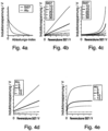
- section b shows the actual time series signal of a detection body made of steel against reference time series signals for a reference detection body made of steel for different distances between 10 mm and 30 mm.
- the actual time series signal of a detection body made of aluminum is plotted against reference time series signals for a reference detection body made of aluminum for distances between 5 mm and 15 mm.
- Each evaluation curve shows a linear progression, i.e. a linear relationship between the actual and reference time series signals.
- the evaluation curves also have a positive slope, with the evaluation curve having a larger slope for a smaller distance from the reference detection object.
- section c the actual time series signal for the steel detection body is plotted against the reference time series signals for the reference detection body made of aluminum and in section e the actual time series signal for the aluminum detection body is plotted against the reference time series signal for the reference detection body made of steel.
- the linearity of the evaluation curve thus indicates the correspondence of the material of the detection body with the material of the reference detection body.
- Logarithmizing the pulse response is based on the assumption that the pulse response decays exponentially when approximated.
- a logarithm of the pulse response as in the figure Figure 5a shown, provides approximately linearly falling curves, especially for non-ferrous metals such as aluminum
- the target object distance can be determined from the axis intercept. However, both courses differ significantly from each other, so that determining the distance would depend on the material.
- the average slope for Alu and St37 shown in the figure Figure 5c differs significantly from each other for all target object distances shown. This parameter can be used to determine to what extent the target object is made of aluminum or St37, regardless of the distance.
- the target object distance can be determined independently of the material from the axis intercept by comparing it with the calibration values stored in the controller.
- logarithm represents a relatively complex calculation operation for a microcontroller, which typically takes several microseconds, even for a modern controller with high clock speeds.
Description
Die Erfindung betrifft eine induktive Annäherungssensoreinheit zum Erfassen eines Erfassungskörpers mit metallischen Eigenschaften und Verfahren zur Bestimmung einer Objekteigenschaft eines metallischen Erfassungskörpers mit einer induktiven Annäherungssensoreinheit.The invention relates to an inductive proximity sensor unit for detecting a detection body with metallic properties and a method for determining an object property of a metallic detection body with an inductive proximity sensor unit.
Gemäß der
Die Sendespule wird mit einer Folge von rechteckförmigen Impulsen erregt und die dadurch ausgelösten Antwortsignale des Magnetfeldsensors der Auswerteschaltung zugeführt. Der Signalverlauf des Antwortsignals wird hinsichtlich von Extremwerten und/oder Nullwerten sowie Amplitudenwerten in vorbestimmten Zeitpunkten ausgewertet. Für die Ermittlung der Abweichung des Material- und/oder Formparameters von Referenzwerten der Parameter und die Überwachung, ob vorgegebene Grenzen der Abweichung eingehalten oder überschritten werden, bildet die Auswerteschaltung Differenzwerte aus den erfassten Werten und den gespeicherten Referenzwerten. Die Differenzwerte werden mit Grenzwerten und/oder Schwellwertfenstern für die Bestimmung eines Material- und/oder Formparameters verglichen.The transmitter coil is excited with a sequence of rectangular pulses and the resulting response signals from the magnetic field sensor are fed to the evaluation circuit. The signal curve of the response signal is evaluated with regard to extreme values and/or zero values as well as amplitude values at predetermined times. For determining the deviation of the material and/or shape parameters from reference values of the parameters and To monitor whether predetermined deviation limits are maintained or exceeded, the evaluation circuit forms difference values from the recorded values and the stored reference values. The difference values are compared with limit values and/or threshold windows for determining a material and/or shape parameter.
Eine Erfassungsspule eines Annäherungssensors wird gemäß der
Aus der
Eine weitere nach dem Pulsauswerteverfahren arbeitende induktive Sensoreinheit ist aus der
In der
Aus der
Weitere Sensoreinrichtungen sind aus der
Vor diesem Hintergrund besteht die Aufgabe der Erfindung darin, eine Vorrichtung anzugeben, die den Stand der Technik weiterbildetAgainst this background, the object of the invention is to provide a device that advances the prior art
Die Aufgabe wird durch eine induktive Annäherungssensoreinheit mit den Merkmalen des Patentanspruchs 1 sowie durch ein Verfahren mit den Merkmalen des Patentanspruchs 5 gelöst. Vorteilhafte Ausgestaltungen der Erfindung sind Gegenstand von Unteransprüchen.The task is solved by an inductive proximity sensor unit with the features of patent claim 1 and by a method with the features of
Gemäß dem Gegenstand der Erfindung wird eine induktive Annäherungssensoreinheit zum Erfassen eines Erfassungskörpers, wobei der Erfassungskörper metallische Eigenschaften aufweist, bereitgestellt.According to the subject matter of the invention, an inductive proximity sensor unit for detecting a detection body, the detection body having metallic properties, is provided.
Die induktive Annäherungssensoreinheit weist eine mit einzelnen zeitlich voneinander beabstandeten pulsförmigen Signalen beaufschlagte Sensorspule, eine Auswerteeinheit und eine Speichereinheit auf.The inductive proximity sensor unit has a sensor coil supplied with individual pulse-shaped signals spaced apart in time, an evaluation unit and a storage unit.
Die Auswerteeinheit ist ausgebildet, Werte für Spannung oder Strom des pulsförmigen Signals an mehreren Abtastzeitpunkten zu messen und aus den gemessenen Werten ein Ist-Zeitreihensignal zu ermitteln.The evaluation unit is designed to measure values for voltage or current of the pulse-shaped signal at several sampling times and to determine an actual time series signal from the measured values.
In der Speichereinheit sind für den Erfassungskörper wenigstens drei Werte eines Referenz-Zeitreihensignals abgespeichert.At least three values of a reference time series signal are stored in the storage unit for the detection body.
Die Auswerteeinheit ist außerdem ausgebildet, mittels einer Auswertekurve einen funktionalen Zusammenhang zwischen dem Ist-Zeitreihensignal und dem Referenz-Zeitreihensignal zu ermitteln und den funktionalen Zusammenhang zu prüfen.The evaluation unit is also designed to use an evaluation curve to determine a functional relationship between the actual time series signal and the reference time series signal and to check the functional relationship.
Gemäß einem weiteren Aspekt der Erfindung wird ein Verfahren zur Bestimmung einer Objekteigenschaft eines metallischen Erfassungskörpers mit einer induktiven Annäherungssensoreinheit bereitgestellt.According to a further aspect of the invention, a method for determining an object property of a metallic detection body with an inductive proximity sensor unit is provided.
Die Annäherungssensoreinheit weist eine Sensorspule, eine Ansteuerschaltung, eine Empfangsschaltung, eine Speichereinheit und eine Auswerteeinheit auf.The proximity sensor unit has a sensor coil, a control circuit, a receiving circuit, a storage unit and an evaluation unit.
Die Sensorspule wird mit zeitlich voneinander beabstandeten pulsförmigen Signalen beaufschlagt.The sensor coil is subjected to pulse-shaped signals that are spaced apart in time.
Mittels der Ansteuerschaltung wird an der Sensorspule ein pulsförmiges Anregungssignal angelegt.Using the control circuit, a pulse-shaped excitation signal is applied to the sensor coil.
Des Weiteren werden mittels der Ansteuerschaltung Werte für die Spannung oder den Strom an mehreren Abtastzeitpunkten gemessen.Furthermore, values for the voltage or current are measured at several sampling times using the control circuit.
Von der Auswerteeinheit wird aus den gemessenen Werten ein Ist-Zeitreihensignal ermittelt.The evaluation unit determines an actual time series signal from the measured values.
In der Speichereinheit sind für den Erfassungskörper wenigstens drei Werte eines Referenz-Zeitreihensignals abgelegt.At least three values of a reference time series signal are stored in the storage unit for the detection body.
Gemäß der Erfindung umfasst auch das Ist-Zeitreihensignal mindestens drei Werte.According to the invention, the actual time series signal also includes at least three values.
Mittels der Auswerteeinheit wird ein funktionaler Zusammenhang zwischen dem Ist-Zeitreihensignal und dem Referenz-Zeitreihensignal ermittelt und der funktionale Zusammenhang geprüft.Using the evaluation unit, a functional connection between the actual time series signal and the reference time series signal is determined and the functional connection is checked.
Die Sensorspule wird mittels einzelner Strompuls, also einzelner zeitlich voneinander beabstandeter pulsförmiger Signale angeregt, so dass das von der Spule erzeugte Magnetfeld ab einem ausreichend geringen Abstand des sich nähernden Erfassungskörpers Wirbelströme in dem Erfassungskörper induziert werden. Durch eine Rückwirkung nach dem Trafoprinzip wird in der Sensorspule das Abklingverhalten verändert.The sensor coil is excited by means of individual current pulses, i.e. individual pulse-shaped signals spaced apart in time, so that the magnetic field generated by the coil induces eddy currents in the detection body from a sufficiently small distance from the approaching detection body. The decay behavior in the sensor coil is changed by a reaction based on the transformer principle.
Nach dem Ende des Strompulses, z.B. durch Trennen von der Stromquelle, wird das Abklingen der induzierten Wirbelströme mit der Sensorspule erfasst, wobei das Abklingen der Wirbelströme von dem Abklingen eines Selbstinduktions-Spannungspulses überlagert wird.After the end of the current pulse, for example by disconnecting from the power source, the decay of the induced eddy currents is detected with the sensor coil, the decay of the eddy currents being superimposed by the decay of a self-induction voltage pulse.
Anhand der Überlagerung, d.h. aus der Abweichung des Sensorspulensignals von dem Abklingverhalten des Selbstinduktions-Spannungspulses ohne die Induktion des Erfassungskörpers, lässt sich die Anwesenheit des Erfassungskörpers und / oder der Abstand und / oder zumindest das Erreichen des Schaltabstands ermitteln.Based on the superposition, ie from the deviation of the sensor coil signal from the decay behavior of the self-induction voltage pulse without the induction of the detection body, the presence of the detection body and / or the distance and / or at least the achievement of the Determine the switching distance.
Das Abklingverhalten, auch Impulsantwort genannt, wird beispielsweise durch Abgreifen der Spannung an den beiden Enden der Sensorspule erfasst bzw. abgetastet. Die Spannungs- oder Stromwerte werden zu mehreren Abtastzeitpunkten mittels der Auswerteeinheit als Ist-Zeitreihensignal erfasst.The decay behavior, also called impulse response, is recorded or sampled, for example, by tapping the voltage at the two ends of the sensor coil. The voltage or current values are recorded as an actual time series signal at several sampling times using the evaluation unit.
Die Auswerteeinheit ist außerdem dazu ausgelegt, das Ist-Zeitreihensignal mit einem hinterlegten Referenz-Zeitreihensignal funktional zu verknüpfen, wodurch eine Auswertekurve generiert wird.The evaluation unit is also designed to functionally link the actual time series signal with a stored reference time series signal, whereby an evaluation curve is generated.
Als Referenz-Zeitreihensignal wird ein durch Abtasten der Impulsantwort der Sensorspule für einen Referenz-Erfassungskörper mit einem bekannten Material und in einem festen, gegebenenfalls bekannten Abstand bezeichnet.A reference time series signal is referred to as a reference detection body with a known material and at a fixed, possibly known, distance by scanning the impulse response of the sensor coil.
Die Auswertekurve ermöglicht es, Eigenschaften des Erfassungsobjekts, wie z.B. das Material des Erfassungskörpers, zu ermitteln. Hierdurch ermöglicht die Auswertekurve beispielsweise eine materialunabhängige Abstandsbestimmung bzw. die zusätzliche Bestimmung des Materials des Erfassungskörpers und damit eine dem ermittelten Material entsprechende Abstandsbestimmung.The evaluation curve makes it possible to determine properties of the detection object, such as the material of the detection body. As a result, the evaluation curve enables, for example, a material-independent distance determination or the additional determination of the material of the detection body and thus a distance determination corresponding to the determined material.
Fehlerhafte Abstandswerte durch eine Abweichung des Materials des Erfassungskörpers von dem Material, für welches eine Referenzkurve zur Abstandsbestimmung hinterlegt ist, werden so zuverlässig vermieden.Incorrect distance values due to a deviation of the material of the detection body from the material for which a reference curve is stored for determining the distance are thus reliably avoided.
Ein Vorteil der induktiven Annäherungssensoreinheit ist, dass zur Ermittlung des funktionalen Zusammenhangs der Auswertekurve nur ein sehr geringer Rechenaufwand notwendig ist. Dadurch ist die erfindungsgemäße Näherungssensoreinheit besonders schnell und zuverlässig.One advantage of the inductive proximity sensor unit is that only very little computing effort is necessary to determine the functional relationship of the evaluation curve. This makes the proximity sensor unit according to the invention particularly fast and reliable.
Ein Weiterer Vorteil ist, dass einfache und kostengünstige Mikrocontroller sich einsetzen lassen und insbesondere mit geringen Prozessortakten gearbeitet werden kann, um hierdurch den Strombedarf bzw. die Verlustleistung des Sensors zu minimieren.Another advantage is that simple and inexpensive microcontrollers can be used and, in particular, low processor clock speeds can be used in order to minimize the power requirement or power loss of the sensor.
Gemäß der Erfindung werden als Verknüpfung mindestens drei Wertepaare aus jeweils drei Werten x1, x2, x3 des Ist-Zeitreihensignals und drei entsprechenden Werten y1, y2, y3 des Referenz-Zeitreihensignals gebildet. Die mindestens drei Wertepaare (xi yi) bilden die Auswertekurve.According to the invention, at least three value pairs are formed as a link from three values x 1 , x 2 , x 3 of the actual time series signal and three corresponding values y 1 , y 2 , y 3 of the reference time series signal. The at least three pairs of values (x i y i ) form the evaluation curve.
Wird die Verknüpfung graphisch dargestellt, d.h. das Ist-Zeitreihensignals wird gegen das Referenz-Zeitreihensignals aufgetragen, entspricht beispielsweise die Abszissenachse der Referenz-Zeitreihe und die Ordinatenachse der Ist-Zeitreihe. Die sich in diesem Koordinatensystem ergebende Auswertekurve stellt ein Teil eines sogenannten Streudiagramms dar.If the link is represented graphically, i.e. the actual time series signal is plotted against the reference time series signal, for example the abscissa axis corresponds to the reference time series and the ordinate axis corresponds to the actual time series. The evaluation curve resulting from this coordinate system represents part of a so-called scatter diagram.
Entspricht das Material des Erfassungskörpers für das Ist-Zeitreihensignal dem Material des verwendeten Referenz-Erfassungskörper zur Erzeugung des Referenz-Zeitreihensignals, so ergibt sich in diesem Ausführungsbeispiel ein linearer Zusammenhang, also eine lineare oder im Wesentlichen lineare Auswerteku rve.If the material of the detection body for the actual time series signal corresponds to the material of the reference detection body used to generate the reference time series signal, a linear relationship results in this exemplary embodiment, i.e. a linear or essentially linear evaluation curve.
Im Unterschied zu dem linearen Zusammenhang entsteht eine stark gekrümmte Auswertekurve, wenn sich die Materialien der Erfassungskörper für Ist- und Referenz-Zeitreihensignal unterscheiden.In contrast to the linear relationship, a strongly curved evaluation curve arises if the materials of the recording bodies for the actual and reference time series signals differ.
Das heißt, dass in der beschriebenen Ausführungsform die Linearität der Auswertekurve ein Maß für das Material der Erfassungskörpers darstellt.This means that in the embodiment described, the linearity of the evaluation curve represents a measure of the material of the detection body.
Es versteht sich, dass auch andere funktionale Zusammenhänge bildbar sind. Werden beispielsweise Wertepaare aus Ist-Zeitreihensignalwerten und quadrierten Referenz-Zeitreihensignalen gebildet, so ergibt sich entsprechend ein quadratischer Anstieg der Auswertekurve bei übereinstimmendem Material von Erfassungskörper und Referenz-Erfassungskörper.It goes without saying that other functional relationships can also be created. For example, if value pairs are formed from actual time series signal values and squared reference time series signals, this results in a corresponding square increase in the evaluation curve if the material of the detection body and reference detection body matches.
Die Linearität der Auswertekurve ist ebenfalls mit sehr geringem rechnerischem Aufwand ermittelbar. Beispielsweise wird das Streudiagramm, also die Auswertekurve mit einer Ausgleichsgeraden y = y0 + a · x genähert, z.B. mittels der Methode der kleinsten Quadrate, so dass sich a wie folgt ergibt: ![]()
![]()
Ein Maß für die Linearität der Auswertekurve ist dann eine Abweichung der Auswertekurve von der ermittelten Ausgleichsgeraden. Die Abweichung wird beispielsweise durch eine mittlere Summe der quadratischen Abweichungen der die Auswertekurve bildenden Wertepaare von Ist- und Referenz-Zeitreihensignal von der Ausgleichsgeraden dargestellt: ![]()
![]()
Gemäß einer alternativen Ausführungsform wird ein Bravais-Pearson-Korrelationskoeffizient gebildet, z. B. als 
![]()
![]()
![]()
![]()
Der entsprechend gebildete Korrelationskoeffizient ist bei negativer Steigung der Auswertekurve negativ und bei einer positiven Steigung der Auswertekurve positiv. Nimmt der Korrelationskoeffizient den Wert 1 bzw. -1 an, so korrelieren die Wertepaare aus Ist- und Referenz-Zeitreihensignal quasi perfekt bzw. der Zusammenhang zwischen Ist- und Referenz-Zeitreihensignal ist linear. Der Korrelationskoeffizient bzw. dessen Abweichung von dem Wert |1| stellt somit in diesem Fall das Maß für die Linearität der Auswertekurve dar.The correspondingly formed correlation coefficient is negative if the slope of the evaluation curve is negative and positive if the slope of the evaluation curve is positive. If the correlation coefficient takes the value 1 or -1, the value pairs from the actual and reference time series signals correlate almost perfectly or the relationship between the actual and reference time series signals is linear. The correlation coefficient or its deviation from the value |1| In this case, it represents the measure of the linearity of the evaluation curve.
Mittels der Verknüpfung des Ist-Zeitreihensignals mit einem Referenz-Zeitreihensignal wird somit, z.B. mittels der vorbeschriebenen Ausführungsformen, aufgrund der aus der Verknüpfung hervorgehenden Auswertekurve festgestellt, ob das Material des Erfassungskörpers mit dem Material des Referenz-Erfassungskörpers übereinstimmt oder nicht.By linking the actual time series signal with a reference time series signal, it is thus determined, for example by means of the above-described embodiments, based on the evaluation curve resulting from the link, whether the material of the detection body matches the material of the reference detection body or not.
Entsprechend ist es möglich, mittels mehrerer Referenz-Zeitreihensignale für unterschiedliche Referenz-Erfassungskörper entsprechende weitere Materialien hinsichtlich des Erfassungskörpers zu ermitteln.Accordingly, it is possible to use several reference time series signals for different reference detection bodies to determine corresponding additional materials with regard to the detection body.
So kann der Abstand eindeutig einer entsprechenden hinterlegten materialspezifischen Verknüpfung von Sensorspulenspannung und Abstand entnommen oder jedem anderen den materialspezifischen Abstand liefernden Zusammenhang entnommen werden.The distance can thus be clearly taken from a corresponding stored material-specific link between sensor coil voltage and distance or from any other connection that provides the material-specific distance.
In einer ersten Ausführungsform ist die Auswerteeinheit ausgebildet, wenigstens eine Objekteigenschaft des Erfassungskörpers zu bestimmen, sofern der funktionale Zusammenhang wenigstens in einem Bereich linear ist.In a first embodiment, the evaluation unit is designed to determine at least one object property of the detection body, provided that the functional relationship is linear at least in one area.
Wird eine Verknüpfung durch Bildung direkter Wertepaare von Werten des Ist- und Referenz-Zeitreihensignals gebildet, so zeigt die Linearität die Übereinstimmung des Materials von Erfassungskörper und Referenzerfassungskörper an. Entsprechend wird beispielsweise das Material des Referenzerfassungskörpers als Eigenschaft des Erfassungskörpers bestimmt. Außerdem ist eine entsprechende Referenzkurve zur Abstandsbestimmung als weitere Eigenschaft des Erfassungskörpers verwendbar.If a link is formed by forming direct value pairs of values of the actual and reference time series signals, the linearity indicates the agreement of the material of the detection body and the reference detection body. Accordingly, for example, the material of the reference detection body is determined as a property of the detection body. In addition, a corresponding reference curve can be used to determine the distance as a further property of the detection body.
Gemäß der Erfindung ist die Auswerteeinheit ausgebildet, als Objekteigenschaft einen Abstand zu dem Erfassungskörper und / oder eine räumliche Orientierung und / oder eine Dicke einer metallischen Schicht des Erfassungskörpers und eine Metallart des Erfassungskörpers zu bestimmen.According to the invention, the evaluation unit is designed to determine, as an object property, a distance to the detection body and/or a spatial orientation and/or a thickness of a metallic layer of the detection body and a type of metal of the detection body.
In einer weiteren Ausführungsform sind in der Speichereinheit für unterschiedliche Arten von Erfassungskörpern jeweils Referenz-Zeitreihensignalen hinterlegt.In a further embodiment, reference time series signals are stored in the storage unit for different types of detection bodies.
Gemäß der Erfindung ist die Auswerteeinheit ausgebildet, ein Linearitätswert der Auswertekurve zu bestimmen und anhand des Linearitätswerts die Materialart des Erfassungskörpers zu bestimmen. Die Linearität ist beispielsweise mittels einer Abweichung zu einer Ausgleichgeraden, z.B. mittels der Methode der kleinsten Quadrate, oder mittels eines Bravais-Pearson-Korrelationskoeffizienten ermittelbar.According to the invention, the evaluation unit is designed to determine a linearity value of the evaluation curve and to determine the type of material of the detection body based on the linearity value. The linearity is For example, it can be determined by means of a deviation from a best-fit line, for example by means of the least squares method, or by means of a Bravais-Pearson correlation coefficient.
Es versteht sich, dass jeweils ein Grenzwert definierbar ist, ab dem von einer ausreichenden Linearität ausgegangen wird und auf eine Materialübereinstimmung zwischen Erfassungskörper und Referenzerfassungskörper geschlossen wird. Beispielsweise wird als Grenzwert für den Bravais-Pearson-Korrelationskoeffizienten mindestens 0,95 oder als Grenzwert für die Abweichung 0,05 oder 0,1 definiert.It goes without saying that a limit value can be defined in each case, from which sufficient linearity is assumed and a material match between the detection body and the reference detection body is concluded. For example, the limit for the Bravais-Pearson correlation coefficient is defined as at least 0.95 or the limit for the deviation is defined as 0.05 or 0.1.
In einer weiteren Weiterbildung ist die Auswerteeinheit ausgebildet, aus der Größe der Steigung der Auswertekurve den Abstand zu dem Erfassungskörper zu bestimmen. Die Steigung der Auswertekurve wird beispielsweise mittels einer Ausgleichskurve ermittelt und es sind beispielsweise Referenzsteigungswerte für unterschiedliche Abstände und gegebenenfalls für unterschiedliche Materialien in der Speichereinheit hinterlegt.In a further development, the evaluation unit is designed to determine the distance to the detection body from the size of the slope of the evaluation curve. The slope of the evaluation curve is determined, for example, by means of a compensation curve and, for example, reference slope values for different distances and possibly for different materials are stored in the storage unit.
In einer anderen Ausführungsform ist die Auswerteeinheit ausgebildet, ein mittleres Ist-Zeitreihensignal aus mehreren aufeinanderfolgenden Ist-Zeitreihensignalen zu bestimmen. Durch die Redundanz wird die Zuverlässigkeit des Messsignals erhöht.In another embodiment, the evaluation unit is designed to determine an average actual time series signal from several successive actual time series signals. The redundancy increases the reliability of the measurement signal.
Mittels der Auswerteeinheit wird ein funktionaler Zusammenhang zwischen dem Ist-Zeitreihensignal und dem Referenz-Zeitreihensignal ermittelt und der funktionale Zusammenhang geprüft. Beispielsweise wird der Abstand zum Erfassungskörper mittels der Auswerteeinheit aus der Steigung des Streudiagramms ermittelt, welches sich ergibt, wenn das Zeitreihensignal und das Referenzsignal gegeneinander aufgetragen werden.Using the evaluation unit, a functional connection between the actual time series signal and the reference time series signal is determined and the functional connection is checked. For example, the distance to the detection body is determined by the evaluation unit from the slope of the scatter diagram, which results when the time series signal and the reference signal are plotted against each other.
In einer Ausführungsform des Verfahrens zur Bestimmung einer Objekteigenschaft eines metallischen Erfassungskörpers wird mittels der Auswerteeinheit wenigstens eine Objekteigenschaft des Erfassungskörpers bestimmt, sofern der funktionale Zusammenhang wenigstens in einem Bereich linear ist.In one embodiment of the method for determining an object property of a metallic detection body, at least one object property of the detection body is determined by means of the evaluation unit, provided that the functional relationship is linear at least in one area.
Gemäß der Erfindung wird mittels der Auswerteeinheit als Objekteigenschaft ein Abstand zu dem Erfassungskörper und / oder eine räumliche Orientierung und / oder eine Dicke einer metallischen Schicht des Erfassungskörpers und eine Metallart des Erfassungskörpers bestimmtAccording to the invention, a distance to the detection body and/or a spatial orientation and/or a thickness of a metallic layer of the detection body and a type of metal of the detection body are determined as object properties by means of the evaluation unit
In einer weiteren Weiterbildung werden die Abtastzeitpunkte des Ist-Zeitreihensignals entsprechend den Abtastzeitpunkten des Referenz-Zeitreihensignals gewählt oder die Abtastzeitpunkte des Ist-Zeitreihensignals und des Referenz-Zeitreihensignals sind dieselben jeweils bezogen auf den Zeitpunkt des Endes des Spannungspulses bzw. des Trennens der Sensorspule von der Versorgungsspannung.In a further development, the sampling times of the actual time series signal are selected in accordance with the sampling times of the reference time series signal or the sampling times of the actual time series signal and the reference time series signal are the same, each based on the time of the end of the voltage pulse or the separation of the sensor coil from the Supply voltage.
In einer weiteren Ausführungsform sind für unterschiedliche Arten von Erfassungskörpern jeweils Referenz-Zeitreihensignalen in der Speichereinheit abgelegt. Hierdurch wird es möglich, entsprechend viele unterschiedliche Materialien zu identifizieren.In a further embodiment, reference time series signals are stored in the memory unit for different types of detection bodies. This makes it possible to identify a corresponding number of different materials.
In einer weiteren Weiterbildung wird mittels der Auswerteeinheit das Ist-Zeitreihensignal logarithmiert und durch Vergleich einer ermittelten Ist-Steigung mit Referenz-Steigungen lässt sich die Materialart des Erfassungskörpers und aus dem y-Achsenabschnitt der Abstand zu dem Erfassungskörper bestimmen.In a further development, the actual time series signal is logarithmized using the evaluation unit and by comparing a determined actual slope with reference slopes, the type of material of the detection body and the distance to the detection body can be determined from the y-axis section.
Gemäß der Erfindung werden drei Wertepaare aus jeweils drei Werten des Ist-Zeitreihensignals und jeweils zugeordneten Werten des Referenz-Zeitreihensignals gebildet. Mittels der Wertepaare wird eine Auswertekurve und ein Linearitätswert bestimmt und anhand des Linearitätswerts die Materialart des Erfassungskörpers bestimmt.According to the invention, three value pairs are formed from three values of the actual time series signal and respectively assigned values of the reference time series signal. Using the value pairs, an evaluation curve and a linearity value are determined and the material type of the detection body is determined based on the linearity value.
In einer weiteren Weiterbildung wird anhand der Größe der Steigung der Auswertekurve der Abstand zu dem Erfassungskörper bestimmt.In a further development, the distance to the detection body is determined based on the size of the slope of the evaluation curve.
Gemäß einer weiteren Ausführungsform wird aus mehreren Ist-Zeitreihensignale ein mittleres Ist-Zeitreihensignal ermittelt.According to a further embodiment, an average actual time series signal is determined from several actual time series signals.
In einer anderen Ausführungsform wird als ein Maß der Übereinstimmung zwischen Ist-Zeitreihensignal und Referenz-Zeitreihensignal eine Summe der quadratischen Abweichungen zwischen der Ausgleichsgeraden und der Auswertekurve gebildet.In another embodiment, a sum of the squared deviations between the compensation line and the evaluation curve is formed as a measure of the agreement between the actual time series signal and the reference time series signal.
In einer weiteren Weiterbildung wird als ein Maß für die Linearität der Auswertekurve zwischen Ist-Zeitreihensignal und Referenz-Zeitreihensignal ein Bravais-Pearson-Korrelationskoeffizient gebildet.In a further development, a Bravais-Pearson correlation coefficient is formed as a measure of the linearity of the evaluation curve between the actual time series signal and the reference time series signal.
In weiteren alternativen Ausführungsformen werden die Werte des Referenz-Zeitreihensignals durch Messen oder durch Simulation erzeugt.In further alternative embodiments, the values of the reference time series signal are generated by measurement or by simulation.
In einer anderen Weiterbildung beträgt ein Zeitintervall zwischen der Anregung des Pulses und dem frühesten Abtastzeitpunkt mindestens 0,04•10-3 s oder mindestens 0,06•10-3 s beträgt. Dieses Zeitintervall wird auch als Totzeit bezeichnet.In another development, a time interval between the excitation of the pulse and the earliest sampling time is at least 0.04 • 10 -3 s or at least 0.06 • 10 -3 s. This time interval is also known as dead time.
In einer anderen Weiterbildung wird mittels der Auswerteeinheit der Abstand zu dem Erfassungskörper unabhängig von den metallischen Eigenschaften bestimmt.In another development, the distance to the detection body is determined using the evaluation unit independently of the metallic properties.
In einer anderen Ausführungsform wird von der Auswerteeinheit nur ein Auswertesignal ausgegeben, wenn die Linearität des Auswertesignals eine vorgegebene Schwelle übersteigt.In another embodiment, the evaluation unit only outputs an evaluation signal if the linearity of the evaluation signal exceeds a predetermined threshold.
In einer weiteren Weiterbildung entsprechen die Abtastzeitpunkte des Ist-Zeitreihensignals den Abtastzeitpunkten des Referenz-Zeitreihensignals oder sind genau gleich. Alternativ erfolgt bei einem Unterschied in den Abtastzeitpunkten eine Interpolation.In a further development, the sampling times of the actual time series signal correspond to the sampling times of the reference time series signal or are exactly the same. Alternatively, if there is a difference in the sampling times, interpolation takes place.
Die Erfindung wird nachfolgend unter Bezugnahme auf die Zeichnungen näher erläutert. Hierbei werden gleichartige Teile mit identischen Bezeichnungen beschriftet. Die dargestellten Ausführungsformen sind stark schematisiert, d.h. die Abstände und die lateralen und die vertikalen Erstreckungen sind nicht maßstäblich und weisen, sofern nicht anders angegeben, auch keine ableitbaren geometrischen Relationen zueinander auf. Darin zeigen, die
- Figur 1
- eine Ansicht auf eine erste erfindungsgemäße Ausführungsform einer induktiven Annäherungssensoreinheit,
- Figur 2
- einen beispielhaften Verlauf einer Schalt- und einer Sensorspulenspannung,
- Figur 3
- beispielhafte Zusammenhänge von Spulenspannung und Abstand,
- Figur 4
- mehrere Referenzkurven für eine materialunabhängige Abstandsbestimmung,
- Figur 5a,b,c
- logarithmierte Verläufe von Spulenspannungen.
- Figure 1
- a view of a first embodiment according to the invention of an inductive proximity sensor unit,
- Figure 2
- an exemplary course of a switching and sensor coil voltage,
- Figure 3
- exemplary relationships between coil voltage and distance,
- Figure 4
- several reference curves for material-independent distance determination,
- Figure 5a,b,c
- logarithmic curves of coil voltages.
Die Abbildung der
Die Sensorspule 12 weist eine Induktivität L und einen Wirkwiderstand RS auf und wird über einen Transistor Q1 und einen Widerstand R3 immer abwechselnd für ein Zeitintervall τ1 mit einer Spannungsquelle V+ als pulsförmiges Signal verbunden und für ein sich anschließendes Zeitintervall τ2 mittels des Transistors Q1 wieder von der Spannungsquelle V+ getrennt, so dass die pulsförmigen Signale jeweils zeitlich voneinander beabstandet sind. Die Steuerspannung Vpuls, des Transistors Q1 ist in Abschnitt b der
Nach dem Trennen der Sensorspule 12 von der Spannungsquelle V+ führt die Selbstinduktion der Sensorspule 12 zu einem Selbstinduktions-Spannungspuls. Ein entsprechender Verlauf der aus der Selbstinduktion stammenden Spannung U2 der Sensorspule 16 ist in Abschnitt c der
Befindet sich der metallische Erfassungskörper in der Nähe der Sensoreinheit 10, so erzeugen die in dem Erfassungskörper induzierten Wirbelströme eine Spannungspulsantwort in der Sensorspule 12, die jedoch den Selbstinduktions-Spannungspuls überlagert. Der zeitliche Verlauf der aus der Überlagerung von Selbstinduktion und Spannungspulsantwort stammenden Spannung U2 an der Sensorspule 12 ist in Abschnitt c der
In dem dargestellten Ausführungsbeispiel weist die Sensoreinheit 10 außerdem einen Bedämpfungswiderstand R4, um insbesondere die Höhe des Selbstinduktionspulses zu reduzieren, eine die Spulenspannung limitierende Diode D2 und eine Verstärkungsschaltung 20 als Teil der Auswerteeinheit 14 auf.In the exemplary embodiment shown, the
Eine nach der Verstärkungsschaltung 20 abgreifbare Spannung U3 der Sensorspule 12 ist in der Abbildung der
Der Zeitpunkt tstart zeigt beispielhaft einen Anfangszeitpunkt für ein Abtasten des Verlaufs der Spannung U3, um den Abstand des Erfassungskörpers zu ermitteln. Im dargestellten Ausführungsbeispiel ist der Zeitpunkt tstart so gewählt, dass der durch die Selbstinduktion erzeugte Spannungsimpuls bereits weitestgehend abgeklungen ist.The time t start shows, by way of example, a starting time for scanning the course of the voltage U 3 in order to determine the distance of the detection body. In the exemplary embodiment shown, the time t start is selected so that the voltage pulse generated by the self-induction has already largely decayed.
Für die weitere Auswertung weist die Auswerteeinheit 14 außerdem eine Recheneinheit 22 mit einer Speichereinheit 16 auf.For further evaluation, the
In der Abbildung der
In Abschnitt a der
Wie aus den beiden Kurven ersichtlich ist, stimmen die Spannungswerte für die beiden unterschiedlichen Materialien nur in einem einzigen, mit einem Pfeil gekennzeichneten Punkt bzw. Abstand überein. Der Abstand A kann somit nicht allein anhand eines Spannungswerts und ohne Informationen über das Material des Erfassungskörpers bestimmt werden.As can be seen from the two curves, the stress values for the two different materials only agree at a single point or distance marked with an arrow. The distance A cannot therefore be determined solely on the basis of a voltage value and without information about the material of the detection body.
In Abschnitt b der
Die in den beiden Abschnitten dargestellten Abstands-Spannungs-Kurven sind für eine Abstandsbestimmung somit nur verwendbar, wenn zusätzlich bekannt ist oder festgestellt werden kann, aus welchem Material der Erfassungskörper besteht.The distance-voltage curves shown in the two sections can therefore only be used to determine the distance if it is also known or can be determined what material the detection body is made of.
Eine weitere Möglichkeit eines Auswertverfahrens mittels Logarithmieren des Spannungsverlaufes wird in Zusammenhang mit der
Daher ist die Recheneinheit 22 erfindungsgemäß dazu ausgelegt, mittels einer Auswertekurve einen funktionalen Zusammenhang zwischen einem aus der Abtastung des Verlaufs der Spannung U3 resultierenden Ist-Zeitreihensignal und mindestens einem in der Speichereinheit 16 hinterlegten Referenz-Zeitreihensignal zu ermitteln, wobei jedes Referenz-Zeitreihensignal dem Abtasten des Verlaufs der Spannung U3 für einen Erfassungskörper mit einem bekannten Material in einem festen, gegebenenfalls bekannten Abstand entspricht.Therefore, according to the invention, the
Das heißt, die Auswertekurve stellt einen funktionalen Zusammenhang zwischen dem Ist-Zeitreihensignal und dem Referenz-Zeitreihensignal her.This means that the evaluation curve establishes a functional connection between the actual time series signal and the reference time series signal.
Anhand der Auswertekurve, d.h. anhand von Eigenschaften der Auswertekurve wie beispielsweise einer Linearität der Auswertekurve, kann auf das Material des Erfassungskörpers zurückgeschlossen werden.Based on the evaluation curve, i.e. based on properties of the evaluation curve such as linearity of the evaluation curve, conclusions can be drawn about the material of the detection body.
In den Abbildungen der
In dem dargestellten Ausführungsbeispiel wird zwischen zwei Materialien unterschieden bzw. der Abstand von Erfassungskörpern ermittelt, welche entweder aus Aluminium (Dreiecke in Abschnitt a der
In der Speichereinheit 16 ist mindestens ein Referenz-Zeitreihensignal für einen aus Aluminium bestehenden Erfassungskörper sowie mindestens ein Referenz-Zeitreihensignal für einen aus Stahl bestehenden Erfassungskörper hinterlegt.At least one reference time series signal for a detection body made of aluminum and at least one reference time series signal for a detection body made of steel are stored in the
Vorteilhafterweise sind die mindestens zwei Referenz-Zeitreihensignal für denselben Abstand des jeweiligen Erfassungskörpers erfasst worden. Gemäß einer anderen Weiterbildung sind jeweils Referenz-Zeitreihensignale für mehrere unterschiedliche Abstände des jeweiligen Erfassungskörpers hinterlegt.Advantageously, the at least two reference time series signals have been recorded for the same distance from the respective detection body. According to another development, reference time series signals are stored for several different distances of the respective detection body.
Der funktionale Zusammenhang wird durch ein Auftragen des abgetasteten Ist-Zeitreihensignals gegen das oder die Referenz-Zeitreihensignale hergestellt. Der sich ergebende Graph wird auch als Streudiagram bezeichnet, die sich ergebende Folge stellt die Auswertekurve dar.The functional connection is established by plotting the sampled actual time series signal against the reference time series signal(s). The resulting graph is also known as a scatter diagram; the resulting sequence represents the evaluation curve.
Wird das für einen Erfassungskörper aus einem ersten Material erfasste Ist-Zeitreihensignal gegenüber einem Referenz-Zeitreihensignal für einen Erfassungskörper desselben Materials aufgetragen, so weist das Streudiagram einen linearen oder zumindest im Wesentlichen linearen Verlauf mit einer positiven Steigung auf.If the actual time series signal recorded for a detection body made of a first material is plotted against a reference time series signal for a detection body of the same material, the scatter diagram has a linear or at least essentially linear course with a positive slope.
Im dargestellten Ausführungsbeispiel ist in dem Abschnitt b das Ist-Zeitreihensignal eines aus Stahl bestehenden Erfassungskörpers gegen Referenz-Zeitreihensignale für einen Referenzerfassungskörper aus Stahl für verschiedene Abstände zwischen 10 mm und 30 mm dargestellt.In the exemplary embodiment shown, section b shows the actual time series signal of a detection body made of steel against reference time series signals for a reference detection body made of steel for different distances between 10 mm and 30 mm.
In Abschnitt d ist das Ist-Zeitreihensignal eines Erfassungskörpers aus Aluminium gegen Referenz-Zeitreihensignale für einen Referenzerfassungskörper aus Aluminium für Abstände zwischen 5 mm und 15 mm aufgetragen. Jede Auswertekurve zeigt einen linearen Verlauf, also einen linearen Zusammenhang zwischen Ist- und Referenz-Zeitreihensignal.In section d, the actual time series signal of a detection body made of aluminum is plotted against reference time series signals for a reference detection body made of aluminum for distances between 5 mm and 15 mm. Each evaluation curve shows a linear progression, i.e. a linear relationship between the actual and reference time series signals.
Die Auswertekurven weisen außerdem eine positive Steigung auf, wobei die Auswertekurve für einen kleineren Abstand des Referenz-Erfassungsobjekts eine größere Steigung aufweist.The evaluation curves also have a positive slope, with the evaluation curve having a larger slope for a smaller distance from the reference detection object.
Für die Streudiagramme der Abschnitte b und d ist der lineare Zusammenhang somit stark ausgeprägt. Ein Bravais-Pearson-Korrelationskoeffizient für diese Auswertekurven resultiert in Werten in einem Bereich zwischen 0.95 und 1.0.The linear relationship is therefore strong for the scatter diagrams in sections b and d. A Bravais-Pearson correlation coefficient for these evaluation curves results in values in a range between 0.95 and 1.0.
In Abschnitt c ist jeweils das Ist-Zeitreihensignal für den Stahl-Erfassungskörper gegen die Referenz-Zeitreihensignale für den Referenzerfassungskörper aus Aluminium aufgetragen und in Abschnitt e das Ist-Zeitreihensignal für den Aluminium-Erfassungskörper gegen die Referenz-Zeitreihensignal für den Referenzerfassungskörper aus Stahl.In section c, the actual time series signal for the steel detection body is plotted against the reference time series signals for the reference detection body made of aluminum and in section e the actual time series signal for the aluminum detection body is plotted against the reference time series signal for the reference detection body made of steel.
In den Abschnitten c und e ist jeweils deutlich ein nicht linearer, stark gekrümmter Zusammenhang zwischen Ist- und Referenz-Zeitreihensignal, also eine nicht lineare Auswertekurve zu erkennen. Der Bravais-Pearson-Korrelationskoeffizient für diese Auswertekurven liegt beispielsweise in einem Bereich von 0,68 bis höchstens 0,83.In sections c and e, a non-linear, strongly curved relationship between the actual and reference time series signals, i.e. a non-linear evaluation curve, can be clearly seen. The Bravais-Pearson correlation coefficient for these evaluation curves is, for example, in a range from 0.68 to a maximum of 0.83.
Die Linearität der Auswertekurve zeigt somit die Übereinstimmung des Materials des Erfassungskörpers mit dem Material des Referenzerfassungskörpers an.The linearity of the evaluation curve thus indicates the correspondence of the material of the detection body with the material of the reference detection body.
In der Abbildung der
In der Abbildung
In der Abbildung
Logarithmieren der Pulsantwort liegt die Annahme zugrunde, dass die Pulsantwort in Näherung exponentiell abklingt. Ein Logarithmieren der Pulsantwort, wie in der Abbildung
Bei Anpassen einer Ausgleichsgerade y=y_0+a·x an die logarithmierten Pulsantworten ergeben sich als Anpassparameter der Achsenabschnitt y_0 bzw. die Steigung a.When adapting a compensation line y=y_0+a x to the logarithmized pulse responses, the axis intercept y_0 or the slope a results as adaptation parameters.
Der Achsenabschnitt, wie in Abbildung der
Aus dem Achsenabschnitt lässt sich also der Zielobjektabstand ermitteln. Allerdings unterscheiden sich beide Verläufe deutlich voneinander, so dass eine Abstandsbestimmung materialabhängig wäre.The target object distance can be determined from the axis intercept. However, both courses differ significantly from each other, so that determining the distance would depend on the material.
Die mittlere Steigung für Alu und St37, dargestellt in der Abbildung
Ist das Material bekannt, lässt sich aus dem Achsenabschnitt durch Vergleich mit im Controller hinterlegten Abgleichwerten der Zielobjektabstand materialunabhängig bestimmen.If the material is known, the target object distance can be determined independently of the material from the axis intercept by comparing it with the calibration values stored in the controller.
Der Logarithmus stellt für einen Mikrocontroller jedoch eine relativ komplexe Rechenoperation dar, welche typischerweise selbst für einen hoch getakteten modernen Controller mehrere Mikrosekunden in Anspruch nimmt.However, the logarithm represents a relatively complex calculation operation for a microcontroller, which typically takes several microseconds, even for a modern controller with high clock speeds.
Des Weiteren müssen für eine hinreichend gute Mittelung viele Abtastwerte berücksichtigt werden, da insbesondere bei kleinen Pulsantworten, d.h. hohen Zielobjektabstände das Signalrauschen aufgrund des Logarithmierens zu einer hohen Fluktuation der ermittelten Fitparameter und damit zu einer geringen Sensitivität, hohen Störanfällig bzw. geringen Bandbreite führt.Furthermore, for a sufficiently good averaging, many sample values must be taken into account, since, particularly with small pulse responses, i.e. high target object distances, the signal noise due to logarithmization leads to a high fluctuation in the determined fit parameters and thus to a low sensitivity, high susceptibility to interference or a low bandwidth.
Claims (13)
- inductive proximity sensor (10) for detecting a detection body, wherein the detection body has metallic properties, comprising- a sensor coil (12) acted on by individual pulse-shaped signals spaced from one another in time,- an evaluating unit (14). wherein the evaluating unit (14) is configured to measure values for voltage or current of the pulse-shaped signal at a plurality of scanning instants and to determine an actual time series signal from the measured values (x1, x2, x3),- a memory unit (16), wherein at least three values (x1, x2, x3) of a reference time series signal are stored in the memory unit (16) for the detection body,
wherein the evaluating unit (14) is configured- to determine from at least three value pairs from each of three values (x1, x2, x3) of the actual time series signal and three corresponding values (y1, y2, y3) of the reference time series signal an evaluation curve as a functional correlation between the actual time series signal and the reference time series signal and- to determine a linearity value of the evaluation curve for checking the functional correlation and- to determine on the basis of the linearity value the kind of metal as object characteristic of the detection body. - inductive proximity sensor (10) according to claim 1, characterised in that the evaluating unit (14) is configured to determine apart from the kind of metal at least one further object characteristic of the detection body insofar as the functional correlation is linear at least in one value range.
- inductive proximity sensor (10) according to claim 1 or claim 2, characterised in that the evaluating unit (14) is configured to determine as further object characteristic a spacing from the detection body and/or a spatial orientation and/or a thickness of a metallic layer of the detection body.
- Inductive proximity sensor (10) according to claim 1 or claim 2, characterised in that the evaluating unit (14) is configured to determine the spacing from the detection body from the magnitude of the gradient of the evaluation curve.
- Method for determining an object characteristic of a metallic detection body by an inductive proximity sensor (10), where- the proximity sensor unit (10) comprises a sensor coil (12), a control circuit, a receiving circuit, a memory unit (16) and an evaluating unit (14),- the sensor coil (12) is acted on by pulse-shaped signals spaced from one another in time, wherein a pulse-shaped excitation signal is applied to the sensor coil (12) by means of the control circuit and values for the voltage or current are measured at several scanning instants,- an actual time series signal is determined by the evaluating unit (14) from the measured values,- at least three values (x1, x2, x3) of a reference time series signal are filed in the memory unit (16) for the detection body, wherein
by means of the evaluating unit (14)- at least three value pairs (xi, yi) from each three values (x1, x2, x3) of the actual time series signal and three corresponding values (y1, y2, y3) of the reference time series signal are formed,- an evaluation curve as a functional correlation between the actual time series signal and the reference time series signal is determined by means of the value pairs (xi, yl),- a linearity value is determined for checking the functional correlation and- the kind of metal is determined as object characteristic of the detection body on the basis of the linearity value. - Method for determining an object characteristic of a metallic detection body according to claim 5, characterised in that at least one further object characteristic of the detection body is determined by means of the evaluating unit (14) sofar as the functional correlation is linear at least in one value range.
- Method for determining an object characteristic of a metallic detection body according to claim 5 or claim 6, characterised in that a spacing from the detection body and/or a spatial orientation and/or a thickness of a metallic layer of the detection body is or are determined as further object characteristic by means of the evaluating unit (14).
- Method for determining an object characteristic of a metallic detection body according to any one of claims 5 to 7, characterised in that respective values (x1, x2, x3) of reference time series signals are filed in the memory unit (16) for different kinds of detection bodies.
- Method for determining an object characteristic of a metallic detection body according to any one of claims 5 to 8, characterised in that the spacing from the detection body is determined on the basis of the magnitude of the gradient of the evaluation curve.
- Method for determining an object characteristic of a metallic detection body according to any one of claims 5 to 9, characterised in that a sum of the square differences between the best-fit line and the reference time series signal is formed as a measure for agreement between actual time series signal and reference time series signal.
- Method for determining an object characteristic of a metallic detection body according to any one of claims 5 to 10, characterised in that a Bravais-Pearson correlation coefficient is formed as a measure for the linearity of the evaluation curve between actual time series signal and reference time series signal.
- Method for determining an object characteristic of a metallic detection body according to any one of claims 5 to 11, characterised in that the spacing from the detection body is determined independently of the metallic characteristics by means of the evaluating unit (14).
- Method for determining an object characteristic of a metallic detection body according to any one of claims 5 to 12, characterised in that only one evaluation signal is issued by the evaluating unit (14) when the linearity of the evaluation signal exceeds a predetermined threshold.
Applications Claiming Priority (1)
| Application Number | Priority Date | Filing Date | Title |
|---|---|---|---|
| DE102021000156.7A DE102021000156A1 (en) | 2021-01-15 | 2021-01-15 | Inductive proximity sensor unit and method for determining an object property of a metallic detection body |
Publications (2)
| Publication Number | Publication Date |
|---|---|
| EP4030199A1 EP4030199A1 (en) | 2022-07-20 |
| EP4030199B1 true EP4030199B1 (en) | 2024-03-06 |
Family
ID=79283077
Family Applications (1)
| Application Number | Title | Priority Date | Filing Date |
|---|---|---|---|
| EP22000001.2A Active EP4030199B1 (en) | 2021-01-15 | 2022-01-04 | Inductive proximity sensor unit and method for determining an object property of a metallic sensing body |
Country Status (2)
| Country | Link |
|---|---|
| EP (1) | EP4030199B1 (en) |
| DE (1) | DE102021000156A1 (en) |
Families Citing this family (1)
| Publication number | Priority date | Publication date | Assignee | Title |
|---|---|---|---|---|
| CN117571814B (en) * | 2023-11-30 | 2024-04-02 | 科瑞工业自动化系统(苏州)有限公司 | Non-contact metal material detection method |
Family Cites Families (7)
| Publication number | Priority date | Publication date | Assignee | Title |
|---|---|---|---|---|
| ATE82451T1 (en) | 1990-12-21 | 1992-11-15 | Detra Sa | INDUCTIVE PROXIMITY SENSOR. |
| DE19506339C2 (en) | 1995-02-23 | 1998-01-15 | Klaus Ebinger | Method and circuit device for the electromagnetic detection of objects |
| DE19530987C1 (en) | 1995-08-23 | 1997-02-13 | Elmed Dr Ing Mense Gmbh | Process for evaluating the signals of a metal detector |
| DE102009058549A1 (en) | 2009-12-17 | 2011-06-22 | ThyssenKrupp Fördertechnik GmbH, 45143 | Detection device for a belt conveyor and method for detecting electrically conductive foreign bodies in the conveyed a belt conveyor |
| US10209097B2 (en) | 2013-03-19 | 2019-02-19 | Balluff Gmbh | Inductive displacement measuring sensor and method for operating the latter |
| DE102013209805A1 (en) | 2013-05-27 | 2014-11-27 | iCONTROLS k.s. | Inductive sensor |
| JP6880861B2 (en) * | 2017-03-15 | 2021-06-02 | オムロン株式会社 | Proximity sensor and detection method |
-
2021
- 2021-01-15 DE DE102021000156.7A patent/DE102021000156A1/en active Pending
-
2022
- 2022-01-04 EP EP22000001.2A patent/EP4030199B1/en active Active
Also Published As
| Publication number | Publication date |
|---|---|
| DE102021000156A1 (en) | 2022-07-21 |
| EP4030199A1 (en) | 2022-07-20 |
Similar Documents
| Publication | Publication Date | Title |
|---|---|---|
| EP1969320B1 (en) | Analysis and compensation circuit for an inductive displacement sensor | |
| EP1847810B1 (en) | Method and device for position detection | |
| EP2312338B1 (en) | Method and device for detecting electrically conductive objects | |
| DE3813739C2 (en) | ||
| WO2012140265A2 (en) | Apparatus and method for detecting electrically conductive items | |
| DE102013104781A1 (en) | Method for monitoring at least one media-specific property of a medium | |
| EP4030199B1 (en) | Inductive proximity sensor unit and method for determining an object property of a metallic sensing body | |
| DE102014207129A1 (en) | A method of detecting an object in a vicinity of an ultrasonic sensor | |
| DE3228447C2 (en) | Measuring method for the detection of metallic objects and metal detector for carrying out the method | |
| DE102015107221B4 (en) | Electromagnetic proximity sensor and method for detecting a target | |
| DE19506339C2 (en) | Method and circuit device for the electromagnetic detection of objects | |
| WO2014191352A2 (en) | Inductive sensor | |
| EP0654685A2 (en) | Arrangement and method for detecting metal objects | |
| DE2641798C3 (en) | Method and device for the contactless determination of physical or geometric properties | |
| EP2981851B1 (en) | Object locater and method for locating a metallic and/or magnetizable object | |
| EP3829064B1 (en) | Sensor for determining an output value, method for evaluating a sensor signal and method for training an output unit for evaluating a sensor signal | |
| DE102021000157A1 (en) | Inductive proximity sensor unit and method for fault checking in an inductive proximity sensor unit | |
| EP1093224A2 (en) | Pulse detector and method for the detection of sinusoidal pulses | |
| DE102018005248A1 (en) | Capacitive sensor system for touch detection | |
| DE102017003657A1 (en) | Method for evaluating a sensor system and device for carrying out a corresponding method | |
| EP0283650B1 (en) | Measuring device for the form of screw-shaped components | |
| EP3495765A1 (en) | Method and device for measuring the thickness of non-magnetizable layers on a magnetizable base material | |
| EP4030135B1 (en) | Inductive sensor unit | |
| DE2705624A1 (en) | MEASURING DEVICE | |
| WO2022078970A1 (en) | Method for inductively analysing metal objects, and associated measuring arrangement |
Legal Events
| Date | Code | Title | Description |
|---|---|---|---|
| PUAI | Public reference made under article 153(3) epc to a published international application that has entered the european phase |
Free format text: ORIGINAL CODE: 0009012 |
|
| STAA | Information on the status of an ep patent application or granted ep patent |
Free format text: STATUS: THE APPLICATION HAS BEEN PUBLISHED |
|
| AK | Designated contracting states |
Kind code of ref document: A1 Designated state(s): AL AT BE BG CH CY CZ DE DK EE ES FI FR GB GR HR HU IE IS IT LI LT LU LV MC MK MT NL NO PL PT RO RS SE SI SK SM TR |
|
| STAA | Information on the status of an ep patent application or granted ep patent |
Free format text: STATUS: REQUEST FOR EXAMINATION WAS MADE |
|
| 17P | Request for examination filed |
Effective date: 20221103 |
|
| RBV | Designated contracting states (corrected) |
Designated state(s): AL AT BE BG CH CY CZ DE DK EE ES FI FR GB GR HR HU IE IS IT LI LT LU LV MC MK MT NL NO PL PT RO RS SE SI SK SM TR |
|
| GRAP | Despatch of communication of intention to grant a patent |
Free format text: ORIGINAL CODE: EPIDOSNIGR1 |
|
| STAA | Information on the status of an ep patent application or granted ep patent |
Free format text: STATUS: GRANT OF PATENT IS INTENDED |
|
| INTG | Intention to grant announced |
Effective date: 20231128 |
|
| GRAS | Grant fee paid |
Free format text: ORIGINAL CODE: EPIDOSNIGR3 |
|
| GRAA | (expected) grant |
Free format text: ORIGINAL CODE: 0009210 |
|
| STAA | Information on the status of an ep patent application or granted ep patent |
Free format text: STATUS: THE PATENT HAS BEEN GRANTED |
|
| AK | Designated contracting states |
Kind code of ref document: B1 Designated state(s): AL AT BE BG CH CY CZ DE DK EE ES FI FR GB GR HR HU IE IS IT LI LT LU LV MC MK MT NL NO PL PT RO RS SE SI SK SM TR |
|
| REG | Reference to a national code |
Ref country code: CH Ref legal event code: EP |
|
| REG | Reference to a national code |
Ref country code: DE Ref legal event code: R096 Ref document number: 502022000573 Country of ref document: DE |
|
| REG | Reference to a national code |
Ref country code: IE Ref legal event code: FG4D Free format text: LANGUAGE OF EP DOCUMENT: GERMAN |