EP3090916A1 - Assembly comprising a seat device and a holding element for the seat device, for arrangement in a railway vehicle, method for transferring the seat device from a stowed position to a usable position and railway vehicle with at least one assembly - Google Patents
Assembly comprising a seat device and a holding element for the seat device, for arrangement in a railway vehicle, method for transferring the seat device from a stowed position to a usable position and railway vehicle with at least one assembly Download PDFInfo
- Publication number
- EP3090916A1 EP3090916A1 EP16167855.2A EP16167855A EP3090916A1 EP 3090916 A1 EP3090916 A1 EP 3090916A1 EP 16167855 A EP16167855 A EP 16167855A EP 3090916 A1 EP3090916 A1 EP 3090916A1
- Authority
- EP
- European Patent Office
- Prior art keywords
- seat
- assembly
- seat device
- holder
- rail vehicle
- Prior art date
- Legal status (The legal status is an assumption and is not a legal conclusion. Google has not performed a legal analysis and makes no representation as to the accuracy of the status listed.)
- Granted
Links
Images


Classifications
-
- B—PERFORMING OPERATIONS; TRANSPORTING
- B61—RAILWAYS
- B61D—BODY DETAILS OR KINDS OF RAILWAY VEHICLES
- B61D33/00—Seats
- B61D33/0057—Seats characterised by their mounting in vehicles
- B61D33/0078—Seats characterised by their mounting in vehicles adjustably mounted
-
- B—PERFORMING OPERATIONS; TRANSPORTING
- B60—VEHICLES IN GENERAL
- B60N—SEATS SPECIALLY ADAPTED FOR VEHICLES; VEHICLE PASSENGER ACCOMMODATION NOT OTHERWISE PROVIDED FOR
- B60N2/00—Seats specially adapted for vehicles; Arrangement or mounting of seats in vehicles
- B60N2/24—Seats specially adapted for vehicles; Arrangement or mounting of seats in vehicles for particular purposes or particular vehicles
- B60N2/30—Non-dismountable or dismountable seats storable in a non-use position, e.g. foldable spare seats
- B60N2/3002—Non-dismountable or dismountable seats storable in a non-use position, e.g. foldable spare seats back-rest movements
- B60N2/3029—Non-dismountable or dismountable seats storable in a non-use position, e.g. foldable spare seats back-rest movements by composed movement
- B60N2/3031—Non-dismountable or dismountable seats storable in a non-use position, e.g. foldable spare seats back-rest movements by composed movement in a longitudinal-vertical plane
-
- B—PERFORMING OPERATIONS; TRANSPORTING
- B60—VEHICLES IN GENERAL
- B60N—SEATS SPECIALLY ADAPTED FOR VEHICLES; VEHICLE PASSENGER ACCOMMODATION NOT OTHERWISE PROVIDED FOR
- B60N2/00—Seats specially adapted for vehicles; Arrangement or mounting of seats in vehicles
- B60N2/24—Seats specially adapted for vehicles; Arrangement or mounting of seats in vehicles for particular purposes or particular vehicles
- B60N2/30—Non-dismountable or dismountable seats storable in a non-use position, e.g. foldable spare seats
- B60N2/3038—Cushion movements
- B60N2/3063—Cushion movements by composed movement
- B60N2/3065—Cushion movements by composed movement in a longitudinal-vertical plane
-
- B—PERFORMING OPERATIONS; TRANSPORTING
- B60—VEHICLES IN GENERAL
- B60N—SEATS SPECIALLY ADAPTED FOR VEHICLES; VEHICLE PASSENGER ACCOMMODATION NOT OTHERWISE PROVIDED FOR
- B60N2/00—Seats specially adapted for vehicles; Arrangement or mounting of seats in vehicles
- B60N2/24—Seats specially adapted for vehicles; Arrangement or mounting of seats in vehicles for particular purposes or particular vehicles
- B60N2/30—Non-dismountable or dismountable seats storable in a non-use position, e.g. foldable spare seats
- B60N2/3088—Non-dismountable or dismountable seats storable in a non-use position, e.g. foldable spare seats characterised by the mechanical link
- B60N2/3093—Non-dismountable or dismountable seats storable in a non-use position, e.g. foldable spare seats characterised by the mechanical link slides
-
- B—PERFORMING OPERATIONS; TRANSPORTING
- B61—RAILWAYS
- B61C—LOCOMOTIVES; MOTOR RAILCARS
- B61C17/00—Arrangement or disposition of parts; Details or accessories not otherwise provided for; Use of control gear and control systems
- B61C17/04—Arrangement or disposition of driving cabins, footplates or engine rooms; Ventilation thereof
Definitions
- the present invention relates to a seat assembly and a bracket for the seat assembly comprising assembly for placement in a rail vehicle, in particular in a tram vehicle, a method for transferring the seat assembly from a stowed position to a use position and a rail vehicle with the assembly.
- the seat device is preferably arranged in a driver's cab of the vehicle.
- Stowable seats for vehicles are used to respond flexibly to changing conditions. For example, it may be necessary to provide the space occupied by the seats for certain objects, such as a wheelchair or luggage.
- This is in US 2004/0113451 A1 a stowable seat assembly indicated for vehicles having a seat formed from the seat and backrest, which are pivotally connected to each other, formed seat, wherein the seat between a use position and two different parking positions is movable.
- the seat can either be moved in the vehicle direction or pivoted by 90 ° relative to the vehicle direction.
- Out CN 201530335 U is a folding seat with a seat and a backrest, which are pivotable against each other shown.
- JP 2006-137265 A is given a folding seat for a vehicle whose seat is pivotable against the backrest.
- the folded seat is housed in a niche of a vehicle wall.
- a similar arrangement is also in GB 2 140 283 A described.
- DE 10 2008 047 659 A1 indicates a foldable seat in a driver's cab, in particular in a rail-bound vehicle.
- the seat comprises a holding frame and a seat supported by the holding frame and pivotable from a use position to an easy exit position and vice versa, and a pivotable backrest.
- the seat surface and the backrest are each arranged in the easy exit position substantially parallel to a plane which extends substantially perpendicular to the respective planes in which the seat surface and the backrest are in the position of use.
- Such a seat can be used in particular as a driving instructor seat in the driver's cab.
- a rail vehicle is specified with a driver's cab, which has a folding seat device.
- This seat assembly is inserted into a Geschränk in which it is then in the folded state.
- the seat device has a seat and a pivoting backrest.
- For retracting the sitting in the folded state seat device in the Geschränk in and out of this telescopic rails are provided.
- the present invention seeks to find an arrangement for a seat device in a rail vehicle, in particular a tram, in which the seat device in the use position allows a comfortable sitting position and claimed in the stowed only small space, so that the reliability of Vehicle is not affected. Furthermore, it is very important that the seat assembly from the use position in the stowed position is quickly convertible to allow in an emergency that the rail vehicle, in particular its driver's station, can be evacuated quickly. Because the device takes in the position of use considerable space in the driver's cab and hinders the exit. In addition, the seat assembly should also ensure that it is simple in construction to ensure that it is not prone to damage and contamination and is also easy to repair.
- 'seat device', 'extension device', '(longitudinal) guide', 'support frame', 'guide element', etc. so may also be understood in each case the corresponding plural forms, namely 'Seats', 'Pull-out devices', '(Longitudinal) guides', 'Supporting frames', 'Guiding elements', etc., and vice versa, unless expressly stated otherwise.
- a structural unit comprising, preferably formed by, a seat device and a mount for the seat device, for arrangement in a rail vehicle.
- these objects are achieved with a method for transferring the seat assembly from a stowage position to a use position.
- the holder of the assembly according to the invention is held by a support member in the rail vehicle.
- the seat device can be transferred from a use position to a stowed position and vice versa.
- the seat device and the at least one holder are connected to each other via corresponding guide means, so that the seat device is movable relative to the at least one holder.
- the corresponding guide means are formed by at least one extension device and at least one corresponding to the at least one extension device guide element (guide element).
- the at least one extension device is articulated via the at least one holder on the support element pivotable.
- the seat assembly is in the stowed position in a substantially vertical position, i. preferably up to ⁇ 30 ° to the vertical, particularly preferably exactly vertical, arranged.
- the rail vehicle is preferably a tram, but may also be another rail-bound vehicle, such as a railcar, a locomotive or other passenger transport vehicle, in particular passenger transport traction vehicle, in local and long-distance transport.
- the present invention can be used in any rail vehicle in which a seat device, in particular in a driver's station, is to be arranged.
- the seat device according to the present invention is to be installed in a driver's cab, there is the possibility that the rail vehicle has a driver's station exclusively at one end, or the rail vehicle can each have a driver's stand at both ends.
- a seat device according to the present invention may be installed in each of the two driver stands or only in one of the two driver stands.
- the seating device according to the invention ensures that it is always available in the rail vehicle, in particular in the driver's cab, and does not have to be procured from another location inside or outside the vehicle if necessary. Because the seat device is permanently installed in the rail vehicle on site.
- the ease of use when setting up or stowing the seat assembly allows their quick availability and also a quick transfer to the stowage position. This is achieved by a simple mechanism provided for this purpose so that the device is always ready for use. This ensures inter alia that the rail vehicle, in particular the driver's station in the rail vehicle, can be evacuated quickly in an emergency.
- the seat device By mounting the seat device on the pivotally supported extension devices a space-saving structure is created, with which the available space is optimally used, especially in the stowed position of the seat assembly.
- the seat device By namely the seat device is arranged in the stowed position in a vertical position, only a small space is required for their placement in the rail vehicle.
- the interior space in the vehicle can be made sufficiently large even if the width of the vehicle is low. Because of the invention, the available interior can be maximized even with a small width of the vehicle. This is achieved by the fact that the seat concept is characterized by a narrow design, so that the space required in the stowed state is minimized.
- the seat device For the person who uses the seat device is with the seat device according to the invention, a satisfactory seating comfort available, since the small design also ensures accommodation of upholstered seats. If the seat assembly is installed in the driver's cab, it can be used as a driving instructor seat. Alternatively, it can also be used as an emergency seat, for example for passengers, to be used. The simple structure of the seat assembly is not prone to damage and contamination and can be easily repaired if necessary.
- the seat device can be accommodated, for example, in a wardrobe in the rail vehicle, in particular in a wardrobe in the driver's cab in the rail vehicle.
- the seat device can be attached via the extension devices to a component of the cabinet, for example on an inner wall, side wall or front wall of the cabinet.
- the seat device can also be fastened to the inner wall of the rail vehicle, in particular to a wall element of the inner or side wall, or to support struts in the wall region of the rail vehicle.
- the space provided for this part of the cabinet or the inner, side or front wall of the rail vehicle is the support element that holds the seat assembly on the extension devices.
- the holder may be designed in the form of a flap drawer.
- the drawer devices may be formed by guide grooves or guide rails attached to inner or side walls of the cabinet or struts supporting the inner wall panels of the rail vehicle or to the flap drawer.
- the extension devices may be located on the seat assembly. In this case, corresponding to the respective extension device guide elements (guide elements) are attached to the support element.
- the seating device in the stowed position is preferably arranged completely in a cavity formed by walls for the interior of the rail vehicle, which is closed to the outside by the vehicle outer skin, for example within a cubicle, in particular in the driver's compartment of the rail vehicle. or, for example, within a cavity, which is separated by inner wall elements from the interior of the rail vehicle, such as a passenger or driver's compartment.
- the seat device is not completely in the stowed position within this cavity but only partially and with the remaining part in the interior of the rail vehicle, such as the driver's compartment, protrudes.
- the seat device is held on two opposite longitudinal sides on the at least one extension device. This allows a stable mounting of the seat device to the support element, since the seat device is held in this case via two extension devices. In principle, it is of course also possible to keep the seat assembly only on one side. This then requires a very solid and robust mount on this side.
- the at least one pull-out device is held pivotably by the support element via the at least one holder so that the seat device can first be pivoted into an operating position with the pull-out device for transferring from the stowage position into the use position toward the operator from which the seat device can be transferred to the position of use.
- the seat device In the operating position, the seat device is inclined relative to the stowage position by a pivot angle ⁇ against the vertical or the stowed position (see below). The pivoting relative to the vertical or relative to the stowage position in the operating position facilitates the operation, because the seat assembly can then simply be pulled upwards from this position and then transferred to the position of use.
- the seat device Before pivoting into the operating position, the walls delimiting the cavity hinder the extension of the seat device into the position of use.
- the seat device is located in a preferred embodiment in the stowed position completely in the cavity and is partially pivoted out by the pivoting of the extension devices in the operating position from the cavity.
- the pull-out devices can preferably be articulated to the support element in its lower area (relative to the arrangement of the seat device in the stowage position).
- the guide elements can preferably in a corresponding to the lower region (relative to the arrangement of the seat device in the stowed position) of the pullout device area be attached to the support element.
- the assembly according to the invention further preferably has a support frame on the side facing the interior of the rail vehicle.
- This support frame serves to support and support the seat assembly in the position of use, so that it is arranged in the position of use in a horizontal position and a person can sit on it.
- the support frame takes on the weight of the seat assembly and sitting on this person.
- the seat device may be equipped instead of a support frame with an auxiliary leg, which can be hinged to the underside of the seat and swung to support the seat device on the bottom surface of the interior of the rail vehicle.
- auxiliary leg which can be hinged to the underside of the seat and swung to support the seat device on the bottom surface of the interior of the rail vehicle.
- the at least one pull-out device is attached to a flap drawer, which is held pivotably by the support element.
- the flap drawer has at least side walls and the outer wall element.
- the at least one holder for the seat device is formed by the flap drawer having the at least one pull-out device.
- the flap drawer is pivotally supported by the support member.
- the seat device is movable relative to and along the extension devices.
- the flap drawer in yet another preferred embodiment of the present invention each having a pull-out device with a guide, preferably with a longitudinal guide, on opposite inner sides, preferably on these side walls have. Because the side walls of the flap drawer are preferably opposite each other, so that the guides can guide and hold the seating device arranged therebetween.
- These guides may be formed by simple guide grooves in the side walls or by guide rails attached to the insides of the side walls.
- the corresponding to the extension devices guide elements are arranged in this case on the seat device.
- guide elements which correspond to extension devices can also be arranged on the side walls of the flap drawer and the drawer devices can be arranged on the seat device.
- the outer wall member of the flap drawer may form part of the outer wall of, for example, a cabinet or the inner wall of the rail vehicle when the seat assembly is in the stowed position.
- This outer wall element can preferably be flush with the rest of the outer wall of the cabinet or the inner wall to the interior of the rail vehicle, so that, apart from any existing joints between this outer wall element and the rest of the wall, together with the remaining wall, a continuous wall surface is formed.
- the side walls and the outer wall element preferably form a box-like structure, namely the flap drawer.
- the side walls may preferably be connected at a right angle to the outer wall element.
- the at least one holder is formed by a respective attachment of the at least one extension device to the support member, and the at least one extension device by at least one (longitudinal) guide, in particular in the form of a guide rail , educated.
- the assembly according to the present invention no flap loading, but only the extension devices, namely guide (s), preferably longitudinal guides, and in particular guide rails.
- the at least one extension device is therefore not fastened to the box-like wall elements of the flap drawer.
- the holder further preferably has a support frame in this embodiment, which is provided instead of the outer wall element of the first embodiment variant.
- the flap drawer in this embodiment variant can also be replaced by guide elements corresponding to the drawer devices on the seat device.
- a support frame is preferably provided in this second embodiment that is located on the side facing the interior of the rail vehicle (longitudinal) - guides.
- the support frame may be formed by a scaffold made of metal or plastic, which is formed for example of bands or tubes or rods or profile strands.
- a bracket with a horizontal support surface. It is preferably pivotable together with the guides on the support element held and is pivoted together with these from the stowed in the operating position and vice versa.
- the (longitudinal) guide of the pull-out device in each of the embodiments and forms described above is preferably formed by an elongated Konkavprofilelement, more preferably at least one guide element, for example on the seat device, translationally movable therein , particularly preferably form-fitting, holds.
- the (longitudinal) guide can be in the form of a profile rail, for example made of metal or plastic.
- the at least one guide element, for example on the seat device is preferably formed by a rotatable element which, for example, rolls on a running surface of the (longitudinal) guide, preferably on a running surface on the inner surface of the concave profile.
- the at least one guide element can also be designed in the form of a (non-rolling) sliding element.
- a pull-out device may be formed in the form of at least one groove in the side walls of the flap drawer or in wall-like elements.
- the extension devices are preferably equipped with upper stop devices so that the seat device can not escape from the guide during retraction, i. that, for example, the guide elements always run within the concave profile and this can not leave.
- the (longitudinal) guides can be closed at the ends by a barrier, in particular at the pivot point of the extension device on the support element opposite end.
- the extension devices are formed by (longitudinal) guides, if, in addition, a support frame is present, on which rest the seat assembly in the position of use and can support.
- the support frame limited as the flap drawer in the case of the first embodiment, the pivoting of the seat assembly from a position parallel to the (longitudinal) guides the guide rails.
- the at least one pull-out device or the flap drawer can be pivotable by a maximum pivot angle ⁇ relative to the support element.
- angle limiting devices can be provided which prevent the extension device or the flap drawer from being pivoted beyond the maximum pivot angle ⁇ out of the stowed position.
- the angle limiting devices can be realized by a flexible connecting element, such as a chain, which is fastened with its ends to the supporting element and a pull-out device or the flap drawer.
- the angle limiting devices may also be formed by stop blocks, which are located on the support member, ie there attached or integral part of this element, and against which the pull-out devices or the flap drawer strike during pivoting.
- the maximum pivot angle ⁇ may preferably be in a range of 5 ° to 85 °, more preferably in a range of 10 ° to 45 °, more preferably in a range of 15 ° to 30 °, and most preferably at about 20 °, relative to the stowage position of the pullout device or flap drawer.
- the seat device is formed by a seat surface and a backrest, which are articulated to each other (folding seat), so that the seat surface and the backrest in the stowed position can be arranged adjacent to each other.
- the sides of the seat surface and the back rest are preferably adjacent to one another, which come into contact with the user in the position of use, for example, there existing upholstery elements.
- the seat and the backrest are preferably each formed by a frame and a pad attached thereto.
- the pads come into contact with each other.
- the seat and the backrest of the seat device are preferably hinged to each other via a hinge.
- the seat device has only a seat, but not a backrest.
- the seat is in the position of use in a horizontal position on the at least one maximum against the support member pivoted support frame, so that a person can take a seat on the seat comfortably.
- levels of the upper stop devices on the extension devices and the upper edge of the support frame or the outer wall element of the flap drawer are to be aligned with each other in a suitable manner.
- the seat device can be arranged on the support element in such a way that the pivot axis about which the extension devices are pivotable relative to the support element extends parallel to the axis about which the seat surface and the backrest are pivotable relative to one another.
- the backrest can be raised towards the inner wall of the rail vehicle in order to convert the seat device into the position of use.
- the person sitting on it can in this case look into the interior of the vehicle.
- the seat device forms an emergency seat, which can be used not only in the driver's cab of the rail vehicle but in the entire rail vehicle, for example, for passengers.
- the seat device or a flap drawer holding the seat device can be locked against pivoting, so that the seat device can not be unintentionally swung out of the cavity.
- the lock can also be designed to prevent unauthorized use (obstruction).
- For locking serve conventional devices, such as snaps, hooks, magnetic locks, Vorlienen with locking devices and the like.
- the seat device Since the holder for the seat device, for example, in the lower region in the cabinet preferably via joints, which allow pivoting about a horizontal axis is stored, the seat device can be swung out with the flap drawer by a pivot angle ⁇ of, for example 20 ° from the vertical forward. As a result, the arranged in the flap load seat assembly is visible. In this position, the seat assembly is in the operating position.
- the seat assembly - initially in the configuration with adjoining seat and backrest - guided by the (longitudinal) guides out of the flap drawer are pulled upwards.
- This translational operation ends at upper stops on the (longitudinal) guides / guide rails.
- the package of seat and backrest is tilted in the horizontal / pivoted until it rests on the outer wall element of the flap drawer. In this position, the package is oriented horizontally. If the seat assembly has a backrest, it can then be raised, i. either preferably opposite to the direction of travel or to the inner wall of the rail vehicle. In this position, the seat assembly is finally in the position of use.
- the seat device is held, for example, by two separate guide rails with (longitudinal) guides and a support frame or without support frame or if the (longitudinal) guides both aforementioned embodiments not articulated on the support element but on the seat device or integrally formed in the seat assembly. If no support frame is present, an auxiliary leg is extended during pivoting of the seat assembly in the horizontal position, which is then supported on the bottom surface of the interior of the rail vehicle.
- like reference numerals designate like elements and / or elements having the same function.
- the figures do not always show the objects to each other in scale. Furthermore, the size ratios of individual elements to those of others in a figure or between the figures are not in each case to scale shown to each other.
- the assembly 100 according to the invention comprising seat device 200 and holder 300 in a rail vehicle 1 is particularly suitable for use in a driver's station 10 of the rail vehicle.
- a driver's station in a tram vehicle is in Fig. 1 shown.
- the seat device is formed in the present case by a seat 210 and a backrest 220, which are articulated to each other.
- the seat device can alternatively also be formed exclusively by a seat surface.
- the seat device is shown in the configuration of the first arrangement variant with a backrest aligned counter to the direction of travel.
- the assembly 100 is housed in a lateral Geschränk 20 in the present case ( Fig. 1 . 2 ).
- the cabinet forms a support element for the unit.
- the support member may also be a wall element that limits the interior of the rail vehicle to the outside. Therefore, the structural unit according to the invention can also be installed elsewhere in the rail vehicle than in the driver's seat 10, for example in a passenger compartment.
- the assembly 100 according to the invention is formed in a first embodiment by a seat device 200 and a holder 300 in the form of a flap shutter 310.
- This unit is in Fig. 2 reproduced in the stowed position, wherein the seat assembly is not shown for ease of illustration (see Fig. 3 to 5 ).
- the unit is housed in a side cabinet 20.
- the flap drawer forms a hinged compartment which can be pivoted forwardly about a hinge 320 located in the lower region of the flap drawer ( Fig. 3 ). This joint is located laterally in the walls of the cabinet (attachment not shown).
- the flap drawer is formed by a (front) outer wall member 311 and by two side walls 312.
- Fig. 6 the assembly 100 is shown with the seat assembly 200 and the holder 300 in the form of the flap tray 310 in a side schematic sectional view, wherein the assembly is installed in the cabinet 20.
- the flap shutter 310 is again formed by an outer wall element 311 and two side walls 312. In each of the two side walls there is a hinge 320 in order to be able to swing the flap drawer out of the cupboard by a pivoting angle ⁇ (cf. Fig. 3 . 7 ).
- the seat device 200 formed by the seat surface 210 and the backrest 220 is fixed.
- the seat and the backrest are hinged to each other via a seat hinge 230, which allows pivoting about a horizontal axis.
- a seat hinge 230 which allows pivoting about a horizontal axis.
- stowage of the assembly 100 are the seat and the backrest to each other.
- the seat is formed by a seat base 211 and a seat cushion 212
- the seat back is constituted by a seatback base body 221 and a seatback cushion 222.
- the two upholstery parts 212, 222 are in the stowed position, as in Fig. 6 shown, against each other.
- the embodiment shown in this figure shows the emergency seat of Fig.
- the seat device 200 is fastened to the flap load 310 by means of guide rails 330 (pull-out devices). On the inside of each of the two side walls 312 of the flap drawer one of these guide rails is arranged.
- the guide rails are opposite each other, so that the seat device with guide elements 231 (corresponding to the extension devices guide elements), such as pins, is guided in the guide rails.
- Fig. 9 is a section AA in the plane of the rotation axis of the seat joint 230 of the seat assembly according to Fig. 6 shown.
- the guide rails form longitudinal guides 331 in the form of slots.
- the slots are located in the guide rails formed by Konkavprofilschienen ( Fig. 6 ).
- the guide elements on the seat device 200, in particular on the seat base body 211 are formed by guide blocks, which are held in the guide rails in a form-fitting manner in the elongate longitudinal guides 331.
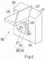
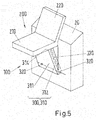
- the seat assembly For transferring the seat device 200 from the stowage position ( Fig. 2 . 6 ) first into an operating position ( Fig. 3 ), then in an upper position with the seat assembly pulled out ( Fig. 7 ) and then into the position of use ( Fig. 5 . 8th ), the seat assembly can be converted for use.
- the seat device 200 Only when the seat device 200 has reached the upper stop 333 of the guide rails 330, it can be pivoted about the hinge axis of the seat joint 230 and the pin 231. In this case, it is conveyed into the horizontal position so that the seat surface rests with its seat base body 211 on the upper edge 314 of the outer wall element 311 (supporting frame) of the flap shutter 310 (FIG. Fig. 5 . 8th ).
- FIG. 10 is, as shown for the second arrangement variant, a sectional view of the assembly 100 with seat 200 and holder 300 (flap load 310) in a cabinet 20 in the upper position also shown for this first arrangement variant. In this case, does not serve the hinge axis of the seat hinge 230 (not shown) for guiding the seat assembly in the guide rails 330 (extension devices).
- the guide elements 231 are attached to fasteners 234 on the seat base body 211 of the seat 210, which project laterally so that they can engage in the longitudinal guides 331 of the guide rails.
- bracket 300 is not formed by a shutter load 310 but by attachment of separate guide rails 330 and a support frame 311 to the support member 20 (not shown in the figures).
- the guide rails are then held without side walls 312 of the flap drawer in the lower joints 320 in the cabinet 20 or other support member and are pivotable about the hinge axis formed by these.
- the support frame replaces the outer wall element 311 of the flap drawer and closes off the space in the cupboard in which the seat device 200 is located.
- the seat device can rest in this case on an upper edge of this frame when it is in the position of use.
Abstract
Zur Platz sparenden Unterbringung einer Sitzeinrichtung 200 in einem Schienenfahrzeug 1 wird erfindungsgemäß eine Baueinheit 100 vorgesehen, die die Sitzeinrichtung 200 und mindestens eine Halterung 300 für die Sitzeinrichtung 200 aufweist. Die mindestens eine Halterung 300 ist in einem Stützelement 20 in dem Schienenfahrzeug 1 gehalten. Die Baueinheit 100 umfasst folgende Merkmale: die Sitzeinrichtung 200 ist von einer Gebrauchsstellung in eine Verstaustellung und umgekehrt überführbar; die Sitzeinrichtung 200 und die mindestens eine Halterung 300 sind über korrespondierende Führungsmittel (231; 330) miteinander verbunden, sodass die Sitzeinrichtung 200 relativ zu der mindestens einen Halterung 300 verfahrbar ist, wobei die korrespondierenden Führungsmittel durch mindestens eine Auszugsvorrichtung 330 und mindestens ein zu der mindestens einen Auszugsvorrichtung 330 korrespondierendes Führungselement 231 gebildet sind; die mindestens eine Auszugsvorrichtung 330 ist über die mindestens eine Halterung (300) an dem Stützelement 20 verschwenkbar angelenkt; die Sitzeinrichtung 200 ist in der Verstaustellung in einer im Wesentlichen senkrechten Lage angeordnet.For space-saving accommodation of a seat device 200 in a rail vehicle 1, a structural unit 100 is provided according to the invention, which has the seat device 200 and at least one holder 300 for the seat device 200. The at least one holder 300 is held in a support element 20 in the rail vehicle 1. The assembly 100 includes the following features: the seat assembly 200 is transferable from a use position to a stowed position and vice versa; the seat device 200 and the at least one holder 300 are connected to one another via corresponding guide means (231; 330), so that the seat device 200 is movable relative to the at least one holder 300, wherein the corresponding guide means by at least one pullout device 330 and at least one to the at least a pull-out device 330 corresponding guide element 231 are formed; the at least one pull-out device 330 is pivotably articulated to the support element 20 via the at least one holder (300); the seat assembly 200 is disposed in the stowed position in a substantially vertical position.
Description
Die vorliegende Erfindung betrifft eine Sitzeinrichtung und eine Halterung für die Sitzeinrichtung umfassende Baueinheit zur Anordnung in einem Schienenfahrzeug, insbesondere in einem Straßenbahn-Fahrzeug, ein Verfahren zum Überführen der Sitzeinrichtung von einer Verstaustellung in eine Gebrauchsstellung sowie ein Schienenfahrzeug mit der Baueinheit. Die Sitzeinrichtung ist vorzugsweise in einem Fahrerstand des Fahrzeuges angeordnet.The present invention relates to a seat assembly and a bracket for the seat assembly comprising assembly for placement in a rail vehicle, in particular in a tram vehicle, a method for transferring the seat assembly from a stowed position to a use position and a rail vehicle with the assembly. The seat device is preferably arranged in a driver's cab of the vehicle.
Verstaubare Sitze für Fahrzeuge werden eingesetzt, um flexibel auf sich verändernde Bedingungen reagieren zu können. Beispielsweise kann es erforderlich sein, den von den Sitzen eingenommenen Platz für bestimmte Objekte, wie zum Beispiel einen Rollstuhl oder Gepäckstücke, bereitzustellen. Hierzu ist in
Eine andere Lösungsmöglichkeit für diesen Zweck ist in
Um die Zugänglichkeit von Fahrzeugeinrichtungen, insbesondere in einem Krankenwagen, zu erleichtern, ist in
Aus
In
In
Für die Installation von Sitzen in Schienenfahrzeugen, insbesondere in einem Fahrerstand einer Straßenbahn, generell aber auch von anderen Schienenfahrzeugen, ist es besonders wichtig, diese Sitzeinrichtungen möglichst platzsparend unterzubringen. Dies gelingt mit den vorhandenen Sitzen nur unvollkommen. Insbesondere die zuletzt genannten in einem Geschränk der Fahrerkabine untergebrachten Sitze erfordern eine erhebliche Einbautiefe, die häufig nicht zur Verfügung steht oder anderweitig benötigt wird. Insbesondere wenn das Fahrzeug eine vorgegebene Gesamtbreite nicht überschreiten darf, kann es durch diese Unterbringung zu Platzproblemen kommen. Darüber hinaus sind einige der bekannten Bauformen, insbesondere diejenigen, bei denen ein Klappsitz in einer Wandnische versenkbar ist, für den Einbau in den Fahrerstand einer Straßenbahn oder eines anderen Schienenfahrzeuges nicht geeignet, da diese Sitze in der Verstaustellung dadurch, dass die Sitzfläche von der Gebrauchsstellung aus nach oben geklappt wird, oberhalb der Sitzfläche Raum beanspruchen würden, der aber nicht zur Verfügung steht. Denn durch die aufgerichtete Rückenlehne wäre die Rundumsicht des Fahrers beeinträchtigt.For the installation of seats in rail vehicles, especially in a driver's cab of a tram, but generally also by other rail vehicles, it is particularly important to accommodate these seats as space-saving. This succeeds only imperfectly with the existing seats. In particular the latter in a Geschränk of Cabins accommodated seats require a considerable installation depth, which is often not available or otherwise needed. In particular, if the vehicle may not exceed a predetermined total width, this accommodation can lead to space problems. In addition, some of the known designs, especially those in which a folding seat is retractable in a wall niche, not suitable for installation in the driver's cab of a tram or other rail vehicle, since these seats in the stowed position in that the seat of the use position is turned up, would claim above the seat space, but is not available. Because of the upright backrest, the all-round view of the driver would be impaired.
Von daher liegt der vorliegenden Erfindung die Aufgabe zugrunde, eine Anordnung für eine Sitzeinrichtung in einem Schienenfahrzeug, insbesondere einer Straßenbahn, zu finden, bei der die Sitzeinrichtung in der Gebrauchsstellung eine bequeme Sitzhaltung ermöglicht und in der Verstaustellung nur geringen Raum beansprucht, sodass die Betriebssicherheit des Fahrzeuges nicht beeinträchtigt ist. Des Weiteren ist es sehr wichtig, dass die Sitzeinrichtung von der Gebrauchsstellung in die Verstaustellung schnell überführbar ist, um in einem Notfall zu ermöglichen, dass das Schienenfahrzeug, insbesondere dessen Fahrerstand, schnell evakuiert werden kann. Denn die Einrichtung nimmt in der Gebrauchsstellung erheblichen Raum im Fahrerstand ein und behindert den Ausstieg. Darüber hinaus soll mit der Sitzeinrichtung auch gewährleistet sein, dass sie einfach aufgebaut ist, um sicherzustellen, dass sie für Beschädigungen und Verunreinigungen nicht anfällig und außerdem leicht reparierbar ist.Therefore, the present invention seeks to find an arrangement for a seat device in a rail vehicle, in particular a tram, in which the seat device in the use position allows a comfortable sitting position and claimed in the stowed only small space, so that the reliability of Vehicle is not affected. Furthermore, it is very important that the seat assembly from the use position in the stowed position is quickly convertible to allow in an emergency that the rail vehicle, in particular its driver's station, can be evacuated quickly. Because the device takes in the position of use considerable space in the driver's cab and hinders the exit. In addition, the seat assembly should also ensure that it is simple in construction to ensure that it is not prone to damage and contamination and is also easy to repair.
Soweit nachfolgend jeweils Begriffe in der Singularform verwendet werden, beispielsweise 'Sitzeinrichtung', 'Auszugsvorrichtung', '(Längs-)Führung', 'Auflagegestell', 'Leitelement' usw., so können darunter jeweils auch die entsprechenden Pluralformen zu verstehen sein, nämlich 'Sitzeinrichtungen', 'Auszugsvorrichtungen', '(Längs-)Führungen', 'Auflagegestelle', 'Leitelementte' usw. und umgekehrt, sofern nicht ausdrücklich etwas anderes angegeben ist.As far as subsequently terms are used in the singular form, for example, 'seat device', 'extension device', '(longitudinal) guide', 'support frame', 'guide element', etc., so may also be understood in each case the corresponding plural forms, namely 'Seats', 'Pull-out devices', '(Longitudinal) guides', 'Supporting frames', 'Guiding elements', etc., and vice versa, unless expressly stated otherwise.
Gemäß einem ersten Aspekt der vorliegenden Erfindung werden diese Aufgaben mit einer Baueinheit, umfassend, vorzugsweise gebildet durch, eine Sitzeinrichtung und eine Halterung für die Sitzeinrichtung, zur Anordnung in einem Schienenfahrzeug gelöst.According to a first aspect of the present invention, these objects are achieved with a structural unit comprising, preferably formed by, a seat device and a mount for the seat device, for arrangement in a rail vehicle.
Gemäß einem zweiten Aspekt der vorliegenden Erfindung werden diese Aufgaben mit einem Verfahren zum Überführen der Sitzeinrichtung von einer Verstaustellung in eine Gebrauchsstellung gelöst.According to a second aspect of the present invention, these objects are achieved with a method for transferring the seat assembly from a stowage position to a use position.
Gemäß einem dritten Aspekt der vorliegenden Erfindung werden diese Aufgaben mit einem Schienenfahrzeug mit mindestens einer erfindungsgemäßen Baueinheit gelöst.According to a third aspect of the present invention, these objects are achieved with a rail vehicle having at least one structural unit according to the invention.
In erfindungsgemäßer Art und Weise ist die Halterung der erfindungsgemäßen Baueinheit von einem Stützelement in dem Schienenfahrzeug gehalten. Die Sitzeinrichtung ist von einer Gebrauchsstellung in eine Verstaustellung und umgekehrt überführbar. Die Sitzeinrichtung und die mindestens eine Halterung sind über korrespondierende Führungsmittel miteinander verbunden, sodass die Sitzeinrichtung relativ zu der mindestens einen Halterung verfahrbar ist. Die korrespondierenden Führungsmittel sind durch mindestens eine Auszugsvorrichtung und mindestens ein zu der mindestens einen Auszugsvorrichtung korrespondierendes Führungselement (Leitelement) gebildet. Die mindestens eine Auszugsvorrichtung ist über die mindestens eine Halterung an dem Stützelement verschwenkbar angelenkt. Die Sitzeinrichtung ist in der Verstaustellung in einer im Wesentlichen senkrechten Lage, d.h. vorzugsweise bis zu ± 30° zur Senkrechten, besonders bevorzugt genau senkrecht, angeordnet.In accordance with the invention, the holder of the assembly according to the invention is held by a support member in the rail vehicle. The seat device can be transferred from a use position to a stowed position and vice versa. The seat device and the at least one holder are connected to each other via corresponding guide means, so that the seat device is movable relative to the at least one holder. The corresponding guide means are formed by at least one extension device and at least one corresponding to the at least one extension device guide element (guide element). The at least one extension device is articulated via the at least one holder on the support element pivotable. The seat assembly is in the stowed position in a substantially vertical position, i. preferably up to ± 30 ° to the vertical, particularly preferably exactly vertical, arranged.
Das Schienenfahrzeug ist vorzugsweise eine Straßenbahn, kann aber auch ein anderes schienengebundenes Fahrzeug sein, wie beispielsweise ein Schienentriebfahrzeug, eine Lokomotive oder ein anderes Personenbeförderungsfahrzeug, insbesondere Personenbeförderungstriebfahrzeug, im Nah- und Fernverkehr. Grundsätzlich ist die vorliegende Erfindung in jedem Schienenfahrzeug einsetzbar, in dem eine Sitzeinrichtung, insbesondere in einem Fahrerstand, angeordnet werden soll. Für den Fall, dass die Sitzeinrichtung gemäß der vorliegenden Erfindung in einem Fahrerstand eingebaut sein soll, besteht die Möglichkeit, dass das Schienenfahrzeug ausschließlich an einem Ende einen Fahrerstand aufweist, oder das Schienenfahrzeug kann an beiden Enden jeweils einen Fahrerstand aufweisen. In letzterem Falle kann in jedem der beiden Fahrerstände oder nur in einem der beiden Fahrerstände eine Sitzeinrichtung gemäß der vorliegenden Erfindung installiert sein. Grundsätzlich ist es auch möglich, dass eine oder mehrere Sitzeinrichtungen gemäß der vorliegenden Erfindung im Passagierraum des Schienenfahrzeuges installiert sind.The rail vehicle is preferably a tram, but may also be another rail-bound vehicle, such as a railcar, a locomotive or other passenger transport vehicle, in particular passenger transport traction vehicle, in local and long-distance transport. In principle, the present invention can be used in any rail vehicle in which a seat device, in particular in a driver's station, is to be arranged. In the event that the seat device according to the present invention is to be installed in a driver's cab, there is the possibility that the rail vehicle has a driver's station exclusively at one end, or the rail vehicle can each have a driver's stand at both ends. In the latter case, a seat device according to the present invention may be installed in each of the two driver stands or only in one of the two driver stands. In principle, it is also possible for one or more seat devices according to the present invention to be installed in the passenger compartment of the rail vehicle.
Mit der erfindungsgemäßen Sitzeinrichtung ist gewährleistet, dass diese im Schienenfahrzeug, insbesondere im Fahrerstand, stets zur Verfügung steht und nicht bei Bedarf erst von einem anderen Ort innerhalb oder außerhalb des Fahrzeuges beschafft werden muss. Denn die Sitzeinrichtung ist in dem Schienenfahrzeug vor Ort fest installiert.The seating device according to the invention ensures that it is always available in the rail vehicle, in particular in the driver's cab, and does not have to be procured from another location inside or outside the vehicle if necessary. Because the seat device is permanently installed in the rail vehicle on site.
Die einfache Handhabung beim Aufstellen oder Verstauen der Sitzeinrichtung ermöglicht deren schnelle Verfügbarkeit und ebenso auch eine schnelle Überführung in die Verstaustellung. Dies wird durch einen einfachen Mechanismus, der hierfür vorgesehen ist, erreicht, sodass die Einrichtung stets und sofort einsatzbereit ist. Dadurch ist unter anderem gewährleistet, dass das Schienenfahrzeug, insbesondere der Fahrerstand in dem Schienenfahrzeug, in einem Notfall schnell evakuiert werden kann.The ease of use when setting up or stowing the seat assembly allows their quick availability and also a quick transfer to the stowage position. This is achieved by a simple mechanism provided for this purpose so that the device is always ready for use. This ensures inter alia that the rail vehicle, in particular the driver's station in the rail vehicle, can be evacuated quickly in an emergency.
Durch die Halterung der Sitzeinrichtung über die verschwenkbar gehaltenen Auszugsvorrichtungen wird ein Platz sparender Aufbau geschaffen, mit dem der zur Verfügung stehende Raum insbesondere in der Verstaustellung der Sitzeinrichtung optimal genutzt wird. Indem nämlich die Sitzeinrichtung in der Verstaustellung in einer senkrechten Lage angeordnet ist, wird ein nur kleiner Bauraum für deren Unterbringung im Schienenfahrzeug benötigt. Insbesondere kann der Innenraum in dem Fahrzeug auch dann ausreichend groß ausgelegt werden, wenn die Breite des Fahrzeuges gering ist. Denn durch die Erfindung kann der zur Verfügung stehende Innenraum selbst bei geringer Baubreite des Fahrzeuges maximiert werden. Dies wird dadurch erreicht, dass sich das Sitzkonzept durch eine schmale Bauweise auszeichnet, womit der Platzbedarf im verstauten Zustand minimiert ist.By mounting the seat device on the pivotally supported extension devices a space-saving structure is created, with which the available space is optimally used, especially in the stowed position of the seat assembly. By namely the seat device is arranged in the stowed position in a vertical position, only a small space is required for their placement in the rail vehicle. In particular, the interior space in the vehicle can be made sufficiently large even if the width of the vehicle is low. Because of the invention, the available interior can be maximized even with a small width of the vehicle. This is achieved by the fact that the seat concept is characterized by a narrow design, so that the space required in the stowed state is minimized.
Für die Person, die die Sitzeinrichtung nutzt, steht mit der Sitzeinrichtung gemäß der Erfindung ein befriedigender Sitzkomfort zur Verfügung, da die kleine Bauform auch eine Unterbringung von gepolsterten Sitzen gewährleistet. Falls die Sitzeinrichtung im Fahrerstand installiert ist, kann sie als Fahrlehrersitz genutzt werden. Alternativ kann sie auch als Notsitz, beispielsweise für Passagiere, verwendet werden. Durch den einfachen Aufbau ist die Sitzeinrichtung nicht anfällig für Beschädigungen und Verunreinigungen und kann im Bedarfsfall leicht repariert werden.For the person who uses the seat device is with the seat device according to the invention, a satisfactory seating comfort available, since the small design also ensures accommodation of upholstered seats. If the seat assembly is installed in the driver's cab, it can be used as a driving instructor seat. Alternatively, it can also be used as an emergency seat, for example for passengers, to be used. The simple structure of the seat assembly is not prone to damage and contamination and can be easily repaired if necessary.
Die Sitzeinrichtung kann beispielsweise in einem Geschränk in dem Schienenfahrzeug, insbesondere in einem Geschränk im Fahrerstand in dem Schienenfahrzeug, untergebracht sein. In diesem Falle kann die Sitzeinrichtung über die Auszugsvorrichtungen an einem Bauteil des Geschränks, beispielsweise an einer Innenwand, Seitenwand oder Vorderwand des Geschränks befestigt sein. Alternativ kann die Sitzeinrichtung auch an der Innenwand des Schienenfahrzeuges, insbesondere an einem Wandelement der Innen- oder Seitenwand, oder an Stützstreben im Wandbereich des Schienenfahrzeuges befestigt sein. Somit stellt das hierfür vorgesehene Bauteil des Geschränks oder die Innen-, Seiten- oder Vorderwand des Schienenfahrzeuges das Stützelement dar, das die Sitzeinrichtung über die Auszugsvorrichtungen hält. Beispielsweise kann die Halterung in Form einer Klappenlade ausgebildet sein. Diese kann am Geschränk oder an der Innenwand oder den Stützstreben im Wandbereich des Schienenfahrzeuges angelenkt sein. Die Auszugsvorrichtungen können durch Führungsnuten oder Führungsschienen gebildet sein, die an Innen- bzw. Seitenwänden des Geschränks oder an Stützstreben, die Innenwandelemente des Schienenfahrzeuges halten, oder an der Klappenlade angebracht sein. Alternativ können sich die Auszugsvorrichtungen an der Sitzeinrichtung befinden. In diesem Falle sind zu der jeweiligen Auszugsvorrichtung korrespondierende Führungselemente (Leitelemente) an dem Stützelement befestigt.The seat device can be accommodated, for example, in a wardrobe in the rail vehicle, in particular in a wardrobe in the driver's cab in the rail vehicle. In this case, the seat device can be attached via the extension devices to a component of the cabinet, for example on an inner wall, side wall or front wall of the cabinet. Alternatively, the seat device can also be fastened to the inner wall of the rail vehicle, in particular to a wall element of the inner or side wall, or to support struts in the wall region of the rail vehicle. Thus, the space provided for this part of the cabinet or the inner, side or front wall of the rail vehicle is the support element that holds the seat assembly on the extension devices. For example, the holder may be designed in the form of a flap drawer. This can be hinged to the cabinet or on the inner wall or the support struts in the wall region of the rail vehicle. The drawer devices may be formed by guide grooves or guide rails attached to inner or side walls of the cabinet or struts supporting the inner wall panels of the rail vehicle or to the flap drawer. Alternatively, the extension devices may be located on the seat assembly. In this case, corresponding to the respective extension device guide elements (guide elements) are attached to the support element.
Aus den vorstehenden Erläuterungen ergibt sich, dass die Sitzeinrichtung in der Verstaustellung vorzugsweise vollständig in einem zum Innenraum des Schienenfahrzeuges durch Wände gebildeten Hohlraum angeordnet ist, der nach außen durch die Fahrzeug-Außenhaut abgeschlossen ist, beispielsweise innerhalb eines Geschränks, insbesondere im Fahrerraum des Schienenfahrzeuges, oder beispielsweise innerhalb eines Hohlraumes, der durch innere Wandelemente vom Innenraum des Schienenfahrzeuges, beispielsweise eines Passagier- oder Fahrerraumes, abgetrennt ist. Grundsätzlich ist es natürlich auch denkbar, dass sich die Sitzeinrichtung in der Verstaustellung nicht vollständig innerhalb dieses Hohlraumes befindet sondern nur teilweise und mit dem restlichen Teil in den Innenraum des Schienenfahrzeuges, beispielsweise den Fahrerraum, hineinragt.It can be seen from the above explanations that the seating device in the stowed position is preferably arranged completely in a cavity formed by walls for the interior of the rail vehicle, which is closed to the outside by the vehicle outer skin, for example within a cubicle, in particular in the driver's compartment of the rail vehicle. or, for example, within a cavity, which is separated by inner wall elements from the interior of the rail vehicle, such as a passenger or driver's compartment. In principle, it is of course also conceivable that the seat device is not completely in the stowed position within this cavity but only partially and with the remaining part in the interior of the rail vehicle, such as the driver's compartment, protrudes.
In einer bevorzugten Weiterbildung der vorliegenden Erfindung kann vorgesehen sein, dass die Sitzeinrichtung an zwei einander gegenüberliegenden Längsseiten über die mindestens eine Auszugsvorrichtung gehalten wird. Dies ermöglicht eine stabile Halterung der Sitzeinrichtung an dem Stützelement, da die Sitzeinrichtung in diesem Falle über zwei Auszugsvorrichtungen gehalten wird. Grundsätzlich ist es natürlich auch möglich, die Sitzeinrichtung nur an einer Seite zu halten. Dies erfordert dann eine sehr solide und robuste Halterung an dieser Seite.In a preferred embodiment of the present invention can be provided that the seat device is held on two opposite longitudinal sides on the at least one extension device. This allows a stable mounting of the seat device to the support element, since the seat device is held in this case via two extension devices. In principle, it is of course also possible to keep the seat assembly only on one side. This then requires a very solid and robust mount on this side.
In noch einer weiteren bevorzugten Weiterbildung der vorliegenden Erfindung wird die mindestens eine Auszugsvorrichtung über die mindestens eine Halterung von dem Stützelement verschwenkbar gehalten, sodass die Sitzeinrichtung mit der Auszugsvorrichtung zum Überführen von der Verstau- in die Gebrauchsstellung zum Bediener hin zunächst in eine Bedienungsstellung verschwenkt werden kann, von der aus die Sitzeinrichtung in die Gebrauchsstellung überführbar ist. In der Bedienungsstellung ist die Sitzeinrichtung gegenüber der Verstaustellung um einen Verschwenkwinkel α gegen die Senkrechte oder die Verstaustellung geneigt (siehe unten). Die Verschwenkung gegenüber der Senkrechten oder gegenüber der Verstaustellung in die Bedienungsstellung erleichtert die Bedienung, weil die Sitzeinrichtung aus dieser Stellung dann einfach nach oben gezogen und dann in die Gebrauchsstellung überführt werden kann. Vor dem Verschwenken in die Bedienungsstellung behindern die den Hohlraum begrenzenden Wände das Ausfahren der Sitzeinrichtung in die Gebrauchsstellung. Die Sitzeinrichtung befindet sich in einer bevorzugten Ausführungsform in der Verstaustellung vollständig in dem Hohlraum und wird durch das Verschwenken der Auszugsvorrichtungen in die Bedienungsstellung teilweise aus dem Hohlraum herausgeschwenkt.In yet a further preferred development of the present invention, the at least one pull-out device is held pivotably by the support element via the at least one holder so that the seat device can first be pivoted into an operating position with the pull-out device for transferring from the stowage position into the use position toward the operator from which the seat device can be transferred to the position of use. In the operating position, the seat device is inclined relative to the stowage position by a pivot angle α against the vertical or the stowed position (see below). The pivoting relative to the vertical or relative to the stowage position in the operating position facilitates the operation, because the seat assembly can then simply be pulled upwards from this position and then transferred to the position of use. Before pivoting into the operating position, the walls delimiting the cavity hinder the extension of the seat device into the position of use. The seat device is located in a preferred embodiment in the stowed position completely in the cavity and is partially pivoted out by the pivoting of the extension devices in the operating position from the cavity.
In einer ersten Ausführungsform der vorliegenden Erfindung, in der ein zu einer Auszugsvorrichtung korrespondierendes Führungselement (Leitelement) an der Sitzeinrichtung befestigt ist, können die Auszugsvorrichtungen bevorzugt in deren unterem Bereich (bezogen auf die Anordnung der Sitzeinrichtung in der Verstaustellung) an dem Stützelement angelenkt sein. In einer anderen zweiten Ausführungsform mit hierzu umgekehrter Kinematik, bei der die Auszugsvorrichtungen an der Sitzeinrichtung und die Leitelemente an dem Stützelement angebracht sind, können die Leitelemente bevorzugt in einem dem unteren Bereich (bezogen auf die Anordnung der Sitzeinrichtung in der Verstaustellung) der Auszugsvorrichtung entsprechenden Bereich an dem Stützelement angebracht sein.In a first embodiment of the present invention, in which a guide element (guide element) corresponding to a pull-out device is fastened to the seat device, the pull-out devices can preferably be articulated to the support element in its lower area (relative to the arrangement of the seat device in the stowage position). In another second embodiment with this reverse kinematics, in which the extension devices are mounted on the seat assembly and the guide elements on the support element, the guide elements can preferably in a corresponding to the lower region (relative to the arrangement of the seat device in the stowed position) of the pullout device area be attached to the support element.
In noch einer weiteren bevorzugten Weiterbildung der vorliegenden Erfindung weist die erfindungsgemäße Baueinheit an der zum Innenraum des Schienenfahrzeuges weisenden Seite ferner vorzugsweise ein Auflagegestell auf. Dieses Auflagegestell dient zur Auflage und Abstützung der Sitzeinrichtung in der Gebrauchsstellung, damit diese in der Gebrauchsstellung in einer horizontalen Lage angeordnet ist und sich eine Person darauf setzen kann. Das Auflagegestell nimmt das Gewicht der Sitzeinrichtung und der auf dieser sitzenden Person auf.In yet another preferred embodiment of the present invention, the assembly according to the invention further preferably has a support frame on the side facing the interior of the rail vehicle. This support frame serves to support and support the seat assembly in the position of use, so that it is arranged in the position of use in a horizontal position and a person can sit on it. The support frame takes on the weight of the seat assembly and sitting on this person.
Alternativ hierzu kann die Sitzeinrichtung anstelle eines Auflagegestells auch mit einem Hilfsbein ausgestattet sein, das an der Unterseite der Sitzfläche angelenkt und zum Abstützen der Sitzeinrichtung auf der Bodenfläche des Innenraumes des Schienenfahrzeuges ausgeschwenkt werden kann. Da die Klappenlade gemäß einer ersten Ausführungsvariante der vorliegenden Erfindung (siehe nachfolgend) bereits das äußere Wandelement als Auflagegestell aufweist, kommt diese Ausführungsform mit einem Hilfsbein beispielsweise für eine Anwendung bei der zweiten Ausführungsvariante in Betracht.Alternatively, the seat device may be equipped instead of a support frame with an auxiliary leg, which can be hinged to the underside of the seat and swung to support the seat device on the bottom surface of the interior of the rail vehicle. Since the flap drawer according to a first embodiment of the present invention (see below) already has the outer wall element as a support frame, this embodiment comes with an auxiliary leg, for example, for use in the second embodiment into consideration.
In der ersten Ausführungsvariante der vorliegenden Erfindung ist die mindestens eine Auszugsvorrichtung an einer Klappenlade angebracht, die von dem Stützelement verschwenkbar gehalten wird. Die Klappenlade weist zumindest Seitenwände und das äußere Wandelement auf. Die mindestens eine Halterung für die Sitzeinrichtung ist durch die die mindestens eine Auszugsvorrichtung aufweisende Klappenlade gebildet. Die Klappenlade wird von dem Stützelement verschwenkbar gehalten. In diesem Falle ist die Sitzeinrichtung relativ zu und entlang den Auszugsvorrichtungen verfahrbar. Hierzu kann die Klappenlade in noch einer weiteren bevorzugten Weiterbildung der vorliegenden Erfindung jeweils eine Auszugsvorrichtung mit einer Führung, vorzugsweise mit einer Längsführung, an einander gegenüberliegenden Innenseiten, vorzugsweise an diesen Seitenwänden, aufweisen. Denn die Seitenwände der Klappenlade liegen vorzugsweise einander gegenüber, sodass die Führungen die dazwischen angeordnete Sitzeinrichtung führen und halten können. Diese Führungen können durch einfache Führungsnuten in den Seitenwänden oder durch Führungsschienen, die an den Innenseiten der Seitenwände befestigt sind, gebildet sein. Die zu den Auszugsvorrichtungen korrespondierenden Leitelemente sind in diesem Falle an der Sitzeinrichtung angeordnet. Alternativ können an den Seitenwänden der Klappenlade auch zu Auszugsvorrichtungen korrespondierende Leitelemente und an der Sitzeinrichtung die Auszugsvorrichtungen angeordnet sein.In the first embodiment of the present invention, the at least one pull-out device is attached to a flap drawer, which is held pivotably by the support element. The flap drawer has at least side walls and the outer wall element. The at least one holder for the seat device is formed by the flap drawer having the at least one pull-out device. The flap drawer is pivotally supported by the support member. In this case, the seat device is movable relative to and along the extension devices. For this purpose, the flap drawer in yet another preferred embodiment of the present invention each having a pull-out device with a guide, preferably with a longitudinal guide, on opposite inner sides, preferably on these side walls have. Because the side walls of the flap drawer are preferably opposite each other, so that the guides can guide and hold the seating device arranged therebetween. These guides may be formed by simple guide grooves in the side walls or by guide rails attached to the insides of the side walls. The corresponding to the extension devices guide elements are arranged in this case on the seat device. Alternatively, guide elements which correspond to extension devices can also be arranged on the side walls of the flap drawer and the drawer devices can be arranged on the seat device.
Das äußere Wandelement der Klappenlade kann einen Teil der Außenwand beispielsweise eines Geschränks oder der Innenwand des Schienenfahrzeuges bilden, wenn sich die Sitzeinrichtung in der Verstaustellung befindet. Dieses äußere Wandelement kann mit der restlichen Außenwand des Geschränks oder der Innenwand zum Innenraum des Schienenfahrzeuges vorzugsweise bündig abschließen, sodass, abgesehen von gegebenenfalls vorhandenen Fugen zwischen diesem äußeren Wandelement und der restlichen Wand, zusammen mit der restlichen Wand eine durchgehende Wandfläche gebildet wird.The outer wall member of the flap drawer may form part of the outer wall of, for example, a cabinet or the inner wall of the rail vehicle when the seat assembly is in the stowed position. This outer wall element can preferably be flush with the rest of the outer wall of the cabinet or the inner wall to the interior of the rail vehicle, so that, apart from any existing joints between this outer wall element and the rest of the wall, together with the remaining wall, a continuous wall surface is formed.
Die Seitenwände und das äußere Wandelement bilden vorzugsweise einen kastenähnlichen Aufbau, nämlich die Klappenlade. Hierzu können die Seitenwände vorzugsweise in einem rechten Winkel mit dem äußeren Wandelement verbunden sein.The side walls and the outer wall element preferably form a box-like structure, namely the flap drawer. For this purpose, the side walls may preferably be connected at a right angle to the outer wall element.
In einer zur ersten Ausführungsvariante der vorliegenden Erfindung alternativen zweiten Ausführungsvariante ist die mindestens eine Halterung durch jeweils eine Befestigung der mindestens einen Auszugsvorrichtung an dem Stützelement gebildet, und die mindestens eine Auszugsvorrichtung ist durch jeweils mindestens eine (Längs-)Führung, insbesondere in Form einer Führungsschiene, gebildet. In dieser Ausführungsvariante weist die Baueinheit gemäß der vorliegenden Erfindung keine Klappenlade, sondern lediglich die Auszugsvorrichtungen auf, nämlich Führung(en), vorzugsweise Längsführungen, und insbesondere Führungsschienen. In dieser Variante ist die mindestens eine Auszugsvorrichtung daher nicht an den kastenähnlichen Wandelementen der Klappenlade befestigt. Die Halterung weist in dieser Ausführungsvariante ferner vorzugsweise ein Auflagegestell auf, das anstelle des äußeren Wandelements der ersten Ausführungsvariante vorgesehen ist. Alternativ kann die Klappenlade in dieser Ausführungsvariante auch durch zu den Auszugsvorrichtungen an der Sitzeinrichtung korrespondierende Leitelemente ersetzt sein.In an alternative to the first embodiment of the present invention second embodiment, the at least one holder is formed by a respective attachment of the at least one extension device to the support member, and the at least one extension device by at least one (longitudinal) guide, in particular in the form of a guide rail , educated. In this embodiment, the assembly according to the present invention, no flap loading, but only the extension devices, namely guide (s), preferably longitudinal guides, and in particular guide rails. In this variant, the at least one extension device is therefore not fastened to the box-like wall elements of the flap drawer. The holder further preferably has a support frame in this embodiment, which is provided instead of the outer wall element of the first embodiment variant. Alternatively, the flap drawer in this embodiment variant can also be replaced by guide elements corresponding to the drawer devices on the seat device.
Zusätzlich ist in dieser zweiten Ausführungsvariante vorzugsweise ein Auflagegestell vorgesehen, dass sich an der zum Innenraum des Schienenfahrzeuges weisenden Seite der (Längs-)-Führungen befindet. Das Auflagegestell kann durch ein aus Metall oder Kunststoff hergestelltes Gerüst gebildet sein, das beispielsweise aus Bändern oder Rohren oder Stäben oder Profilsträngen gebildet ist. Beispielsweise kann es durch einen Bügel mit horizontaler Auflagefläche gebildet sein. Es ist vorzugsweise zusammen mit den Führungen an dem Stützelement verschwenkbar gehalten und wird zusammen mit diesen aus der Verstaustellung in die Bedienungsstellung und umgekehrt verschwenkt.In addition, a support frame is preferably provided in this second embodiment that is located on the side facing the interior of the rail vehicle (longitudinal) - guides. The support frame may be formed by a scaffold made of metal or plastic, which is formed for example of bands or tubes or rods or profile strands. For example, it may be formed by a bracket with a horizontal support surface. It is preferably pivotable together with the guides on the support element held and is pivoted together with these from the stowed in the operating position and vice versa.
Die (Längs-)Führung der Auszugsvorrichtung in jeder der vorstehend erläuterten Ausführungsvarianten und -formen (Klappenlade, separate (Längs-)Führungen) wird vorzugsweise durch ein langgestrecktes Konkavprofilelement gebildet, das weiter bevorzugt mindestens ein Leitelement, beispielsweise an der Sitzeinrichtung, darin translatorisch verfahrbar, besonders bevorzugt formschlüssig, hält. Die (Längs-)Führung kann in Form einer Profilschiene, beispielsweise aus Metall oder Kunststoff, ausgebildet sein. Das mindestens eine Leitelement, beispielsweise an der Sitzeinrichtung, ist vorzugsweise durch ein drehbares Element gebildet, das zum Beispiel auf einer Lauffläche der (Längs-)Führung abrollt, vorzugsweise auf einer Lauffläche an der Innenfläche des Konkavprofils. Es kann durch ein Rollen- oder Kugelelement gebildet sein. Alternativ kann das mindestens eine Leitelement auch in Form eines (nicht rollenden) Gleitelements ausgebildet sein. Alternativ dazu kann eine Auszugsvorrichtung in Form mindestens einer Nut in den Seitenwänden der Klappenlade oder in wandähnlichen Elementen gebildet sein.The (longitudinal) guide of the pull-out device in each of the embodiments and forms described above (flap load, separate (longitudinal) guides) is preferably formed by an elongated Konkavprofilelement, more preferably at least one guide element, for example on the seat device, translationally movable therein , particularly preferably form-fitting, holds. The (longitudinal) guide can be in the form of a profile rail, for example made of metal or plastic. The at least one guide element, for example on the seat device, is preferably formed by a rotatable element which, for example, rolls on a running surface of the (longitudinal) guide, preferably on a running surface on the inner surface of the concave profile. It can be formed by a roller or ball element. Alternatively, the at least one guide element can also be designed in the form of a (non-rolling) sliding element. Alternatively, a pull-out device may be formed in the form of at least one groove in the side walls of the flap drawer or in wall-like elements.
Die Auszugsvorrichtungen sind vorzugsweise mit oberen Anschlagsvorrichtungen ausgestattet, damit die Sitzeinrichtung beim Herausfahren nicht aus der Führung austreten kann, d.h. dass beispielsweise die Leitelemente stets innerhalb des Konkavprofils laufen und dieses nicht verlassen können. Hierzu können die (Längs-)Führungen an den Enden durch eine Sperre verschlossen sein, insbesondere an dem der Anlenkstelle der Auszugsvorrichtung am Stützelement gegenüberliegenden Ende.The extension devices are preferably equipped with upper stop devices so that the seat device can not escape from the guide during retraction, i. that, for example, the guide elements always run within the concave profile and this can not leave. For this purpose, the (longitudinal) guides can be closed at the ends by a barrier, in particular at the pivot point of the extension device on the support element opposite end.
Die (Längs-)Führungen und deren Anschlagsvorrichtungen sind dazu ausgebildet, dass die Sitzeinrichtung bei maximalem Ausfahren der Sitzeinrichtung gegenüber den Auszugsvorrichtungen nicht nur parallel zu den (Längs-)Führungen verfahrbar sondern auch gegenüber den (Längs-)Führungen verschwenkbar ist:
- Falls die Auszugsvorrichtungen durch (Längs-)Führungen für die Sitzeinrichtung an oder in den Seitenwänden einer Klappenlade gebildet sind (erste Ausführungsvariante), kann die Sitzeinrichtung über jeweils ein Leitelement mittels der (Längs-)Führungen geführt werden. Dadurch ist eine Verschwenkung von der Bedienungsstellung in die Gebrauchsstellung um eine Achse senkrecht zur Längserstreckung der (Längs-)Führung zwar grundsätzlich möglich. Eine Verschwenkung wird jedoch bei nicht zumindest annähernd vollständigem Ausfahren des Sitzelements gegenüber den Auszugsvorrichtungen dadurch weitgehend verhindert, dass die Klappenlade zum Ausfahren aus der Verstaustellung nur um einen Winkel verschwenkt wird, der kleiner ist als der maximale Verschwenkwinkel α. Das äußere Wandelement der Klappenlade verhindert in diesem Fall, dass die Sitzeinrichtung aus einer Lage parallel zu den (Längs-)Führungen in die Gebrauchsstellung verschwenkt werden kann. Denn die Klappenlade ist vorzugsweise gerade ungefähr so viel aus der Verstaustellung heraus in die Bedienungsstellung verschwenkbar, dass die Sitzeinrichtung aus dem Hohlraum herausgefahren werden kann, ohne dabei durch Einbauten behindert zu werden. Die (Längs-)Führungen der Seitenwände der Klappenlade erstrecken sich vorzugsweise bis auf ein Niveau (vertikaler Abstand zum Bodenniveau des Innenraumes des Schienenfahrzeuges), das höher ist als das Niveau des oberen Randes des äußeren Wandelements der Klappenlade. Dadurch kann die Sitzeinrichtung nach dem vollständigen Ausfahren bis zum Anschlag in eine obere Stellung auf diesem oberen Rand aufliegen.
- If the pull-out devices are formed by (longitudinal) guides for the seat device on or in the side walls of a flap drawer (first embodiment variant), the seat device can be guided via a respective guide element by means of the (longitudinal) guides. As a result, pivoting from the operating position into the position of use about an axis perpendicular to the longitudinal extent of the (longitudinal) guide is basically possible. A pivoting However, it is largely prevented by not at least approximately complete extension of the seat member relative to the extension devices that the flap drawer is pivoted to extend out of the stowed position only by an angle which is smaller than the maximum pivot angle α. The outer wall element of the flap drawer prevents in this case that the seat device can be pivoted from a position parallel to the (longitudinal) guides in the position of use. Because the flap drawer is preferably just about as much from the stowed out in the operating position pivotally that the seat assembly can be moved out of the cavity without being hindered by internals. The (longitudinal) guides of the side walls of the flap drawer preferably extend to a level (vertical distance to the floor level of the interior of the rail vehicle) that is higher than the level of the upper edge of the outer wall element of the flap drawer. This allows the seat assembly after complete extension until it stops in an upper position rest on this upper edge.
Entsprechendes gilt auch für die zweite Ausführungsvariante, bei der die Auszugsvorrichtungen durch (Längs-)Führungen gebildet sind, wenn außerdem ein Auflagegestell vorhanden ist, auf dem die Sitzeinrichtung in der Gebrauchsstellung aufliegen und sich abstützen kann. Das Auflagegestell begrenzt wie die Klappenlade im Falle der ersten Ausführungsvariante die Verschwenkung der Sitzeinrichtung aus einer Lage parallel zu den (Längs-)Führungen der Führungsschienen.The same applies to the second embodiment, in which the extension devices are formed by (longitudinal) guides, if, in addition, a support frame is present, on which rest the seat assembly in the position of use and can support. The support frame limited as the flap drawer in the case of the first embodiment, the pivoting of the seat assembly from a position parallel to the (longitudinal) guides the guide rails.
Ferner kann in noch einer weiteren bevorzugten Weiterbildung der vorliegenden Erfindung auch vorgesehen sein, dass die mindestens eine Auszugsvorrichtung bzw. die Klappenlade um einen maximalen Verschwenkwinkel α gegenüber dem Stützelement verschwenkbar ist. Hierzu können Winkelbegrenzungsvorrichtungen vorgesehen sein, die verhindern, dass die Auszugsvorrichtung bzw. die Klappenlade über den maximalen Verschwenkwinkel α hinaus aus der Verstaustellung heraus verschwenkt wird. Die Winkelbegrenzungsvorrichtungen können durch ein flexibles Verbindungselement, wie eine Kette, das mit seinen Enden an dem Stützelement und einer Auszugsvorrichtung bzw. der Klappenlade befestigt ist, realisiert sein. Alternativ können die Winkelbegrenzungsvorrichtungen auch durch Anschlagsblöcke gebildet sein, die sich an dem Stützelement befinden, d.h. dort angebracht oder integraler Teil dieses Elements sind, und gegen die die Auszugsvorrichtungen bzw. die Klappenlade beim Verschwenken anschlagen. Der maximale Verschwenkwinkel α kann bevorzugt in einem Bereich von 5° bis 85°, weiter bevorzugt in einem Bereich von 10° bis 45°, noch weiter bevorzugt in einem Bereich von 15° bis 30° und am meisten bevorzugt bei etwa 20°, gegenüber der Verstaustellung der Auszugsvorrichtung bzw. Klappenlade liegen.Furthermore, in yet another preferred development of the present invention, provision can also be made for the at least one pull-out device or the flap drawer to be pivotable by a maximum pivot angle α relative to the support element. To this end, angle limiting devices can be provided which prevent the extension device or the flap drawer from being pivoted beyond the maximum pivot angle α out of the stowed position. The angle limiting devices can be realized by a flexible connecting element, such as a chain, which is fastened with its ends to the supporting element and a pull-out device or the flap drawer. Alternatively, the angle limiting devices may also be formed by stop blocks, which are located on the support member, ie there attached or integral part of this element, and against which the pull-out devices or the flap drawer strike during pivoting. The maximum pivot angle α may preferably be in a range of 5 ° to 85 °, more preferably in a range of 10 ° to 45 °, more preferably in a range of 15 ° to 30 °, and most preferably at about 20 °, relative to the stowage position of the pullout device or flap drawer.
Die vorstehenden Ausführungen zur Ausbildung der Auszugsvorrichtungen in der ersten und zweiten Ausführungsvariante sind, wie vorstehend erläutert, ferner auch auf solche Ausführungsformen übertragbar, bei denen die Auszugsvorrichtungen nicht über die Halterungen an dem Stützelement befestigt sondern an der Sitzeinrichtung angeordnet sind, insbesondere an der Sitzfläche. In diesem Falle sind die Leitelemente an seitlich von der Sitzeinrichtung angeordneten Bauteilen an dem Stützelement angeordnet. Die (Längs-)Führungen sind in dieser Ausführungsform vorzugsweise an den Schmalseiten der Sitzeinrichtung, insbesondere der Sitzfläche, beispielsweise durch dort angebrachte Führungsschienen oder dort eingebrachte Führungsausnehmungen (-nuten) gebildet. Die Leitelemente können sich in diesem Falle an Armen befinden, die an den Wandelementen, beispielsweise des Geschränks oder der Innenwand des Schienenfahrzeuges, befestigt sind.The above statements on the design of the extension devices in the first and second embodiment are, as explained above, also applicable to those embodiments in which the extension devices are not attached via the brackets to the support member but are arranged on the seat device, in particular on the seat surface. In this case, the guide elements are arranged on laterally arranged from the seat assembly components on the support member. The (longitudinal) guides are preferably formed in this embodiment on the narrow sides of the seat device, in particular the seat, for example, by guide rails mounted there or there introduced Führungsausnehmungen (grooves). The guide elements may in this case be located on arms which are fastened to the wall elements, for example the cabinet or the inner wall of the rail vehicle.
In noch einer weiteren bevorzugten Weiterbildung der vorliegenden Erfindung ist die Sitzeinrichtung durch eine Sitzfläche und eine Rückenlehne, die aneinander angelenkt sind, gebildet (Klappsitz), sodass die Sitzfläche und die Rückenlehne in der Verstaustellung aneinander anliegend anordenbar sind. In der Verstaustellung liegen vorzugsweise die Seiten der Sitzfläche und der Rückenlehne aneinander an, die in der Gebrauchsstellung mit der benutzenden Person in Kontakt kommen, beispielsweise dort vorhandene Polsterelemente.In yet another preferred embodiment of the present invention, the seat device is formed by a seat surface and a backrest, which are articulated to each other (folding seat), so that the seat surface and the backrest in the stowed position can be arranged adjacent to each other. In the stowage position, the sides of the seat surface and the back rest are preferably adjacent to one another, which come into contact with the user in the position of use, for example, there existing upholstery elements.
Die Sitzfläche und die Rückenlehne sind vorzugsweise jeweils durch ein Rahmengestell und ein daran befestigtes Polster gebildet. Beim Überführen der Sitzeinrichtung in die Verstaustellung kommen vorzugsweise die Polster miteinander in Kontakt.The seat and the backrest are preferably each formed by a frame and a pad attached thereto. When transferring the seat device in the stowed position preferably the pads come into contact with each other.
Die Sitzfläche und die Rückenlehne der Sitzeinrichtung sind vorzugsweise über ein Scharnier aneinander angelenkt.The seat and the backrest of the seat device are preferably hinged to each other via a hinge.
Grundsätzlich ist es auch möglich, dass die Sitzeinrichtung ausschließlich eine Sitzfläche, nicht jedoch eine Rückenlehne aufweist.In principle, it is also possible that the seat device has only a seat, but not a backrest.
In noch einer weiteren bevorzugten Weiterbildung der vorliegenden Erfindung liegt die Sitzfläche in der Gebrauchsstellung in einer horizontalen Lage auf dem mindestens einen maximal gegenüber dem Stützelement verschwenkten Auflagegestell auf, sodass eine Person auf der Sitzfläche bequem Platz nehmen kann. Hierzu sind Niveaus der oberen Anschlagsvorrichtungen an den Auszugsvorrichtungen und des oberen Randes des Auflagegestells oder des äußeren Wandelements der Klappenlade in geeigneter Weise zueinander auszurichten.In yet another preferred embodiment of the present invention, the seat is in the position of use in a horizontal position on the at least one maximum against the support member pivoted support frame, so that a person can take a seat on the seat comfortably. For this purpose, levels of the upper stop devices on the extension devices and the upper edge of the support frame or the outer wall element of the flap drawer are to be aligned with each other in a suitable manner.
In noch einer weiteren Weiterbildung der vorliegenden Erfindung kann die Sitzeinrichtung, wenn diese durch eine Sitzfläche und eine Rückenlehne, die aneinander angelenkt sind, gebildet ist, in mindestens zwei verschiedenen Anordnungen an dem Stützelement gehalten sein:
- In einer ersten Anordnungsvariante kann die Sitzeinrichtung derart an dem Stützelement angeordnet sein, dass die Schwenkachse, um die die Auszugsvorrichtungen gegenüber dem Stützelement verschwenkbar sind, senkrecht zu der Achse verläuft, um die die Sitzfläche und die Rückenlehne gegeneinander verschwenkbar sind (wobei letztere Achse horizontal verläuft). In diesem Falle ist es insbesondere bevorzugt, dass die Rückenlehne entgegen der Fahrtrichtung des Schienenfahrzeuges aufgerichtet werden kann, um die Sitzeinrichtung in die Gebrauchsstellung zu überführen. Die darauf Platz nehmende Person kann in diesem Falle in Fahrtrichtung des Fahrzeuges blicken. Die Sitzeinrichtung kann in diesem Falle vorteilhafter Weise einen Fahrlehrersitz in dem Fahrerstand des Schienenfahrzeuges bilden.
- In a first arrangement variant, the seat device can be arranged on the support element such that the pivot axis about which the extension devices are pivotable relative to the support element is perpendicular to the axis about which the seat surface and the backrest are pivotable relative to each other (the latter axis being horizontal ). In this case, it is particularly preferred that the backrest can be erected counter to the direction of travel of the rail vehicle in order to convert the seat device into the position of use. The person sitting on it can look in this case in the direction of travel of the vehicle. The seat device can in this case advantageously form a driving instructor seat in the driver's cab of the rail vehicle.
In einer zweiten Anordnungsvariante kann die Sitzeinrichtung derart an dem Stützelement angeordnet sein, dass die Schwenkachse, um die die Auszugsvorrichtungen gegenüber dem Stützelement verschwenkbar sind, parallel zu der Achse verläuft, um die die Sitzfläche und die Rückenlehne gegeneinander verschwenkbar sind. In diesem Falle ist es insbesondere bevorzugt, dass die Rückenlehne zur Innenwand des Schienenfahrzeuges hin aufgerichtet werden kann, um die Sitzeinrichtung in die Gebrauchsstellung zu überführen. Die darauf Platz nehmende Person kann in diesem Falle in den Innenraum des Fahrzeuges blicken. In diesem Falle bildet die Sitzeinrichtung einen Notsitz, der nicht nur im Fahrerstand des Schienenfahrzeuges sondern im gesamten Schienenfahrzeug, beispielsweise auch für Passagiere, eingesetzt werden kann.In a second arrangement variant, the seat device can be arranged on the support element in such a way that the pivot axis about which the extension devices are pivotable relative to the support element extends parallel to the axis about which the seat surface and the backrest are pivotable relative to one another. In this case, it is particularly preferred that the backrest can be raised towards the inner wall of the rail vehicle in order to convert the seat device into the position of use. The person sitting on it can in this case look into the interior of the vehicle. In this case, the seat device forms an emergency seat, which can be used not only in the driver's cab of the rail vehicle but in the entire rail vehicle, for example, for passengers.
In noch einer weiteren bevorzugten Weiterbildung der vorliegenden Erfindung ist die Sitzeinrichtung oder eine die Sitzeinrichtung haltende Klappenlade gegen Verschwenken verriegelbar, sodass die Sitzeinrichtung nicht unbeabsichtigt aus dem Hohlraum ausgeschwenkt werden kann. Die Verriegelung kann auch dazu ausgebildet sein, eine unbefugte Benutzung zu verhindern (Versperrung). Zur Verriegelung dienen übliche Vorrichtungen, beispielsweise Schnappverschlüsse, Haken, Magnetverschlüsse, Vorhaltungen mit Schließeinrichtungen und dergleichen.In yet another preferred development of the present invention, the seat device or a flap drawer holding the seat device can be locked against pivoting, so that the seat device can not be unintentionally swung out of the cavity. The lock can also be designed to prevent unauthorized use (obstruction). For locking serve conventional devices, such as snaps, hooks, magnetic locks, Vorhaltungen with locking devices and the like.
Das erfindungsgemäße Verfahren zum Überführen der Sitzeinrichtung von der Verstaustellung in die Gebrauchsstellung umfasst die folgenden Verfahrensschritte:
- (a) Verschwenken der Sitzeinrichtung aus der Verstaustellung in eine Bedienungsposition; in der ersten Ausführungsvariante wird die Sitzeinrichtung zusammen mit der mindestens einen Halterung aus der Verstaustellung in die Bedienungsposition verschwenkt;
- (b) Ausfahren der Sitzeinrichtung aus der Bedienungsposition relativ zu der mindestens einen Halterung bis zu einer oberen Stellung;
- (c) Verschwenken der Sitzeinrichtung aus der oberen Stellung in die Gebrauchsstellung, in der die Sitzeinrichtung in einer horizontalen Stellung angeordnet ist.
- (A) pivoting the seat assembly from the stowed position into an operating position; in the first embodiment, the seat assembly is pivoted together with the at least one holder from the stowed position into the operating position;
- (b) extending the seat assembly from the operating position relative to the at least one bracket to an upper position;
- (C) pivoting the seat assembly from the upper position to the use position, in which the seat device is arranged in a horizontal position.
Für die Überführung von der Gebrauchsstellung in die Verstaustellung wird umgekehrt vorgegangen.The procedure is reversed for the transfer from the use position to the stowage position.
Zur Überführung der Sitzeinrichtung von der Verstaustellung in die Gebrauchsstellung wird im Einzelnen in einem Schiebe/Zieh-Klapp-Mechanismus in der Ausführungsvariante mit der Klappenlade wie folgt vorgegangen:
- Die Sitzeinrichtung ist mit ihren Leitelementen beispielsweise in (Längs-)Führungen seitlicher Führungsschienen geführt, sodass diese ungefähr am unteren Ende dieser (Längs-)Führungen platziert sind. Die Führungsschienen sind ebenso wie die Sitzeinrichtung in im Wesentlichen senkrechter Lage in einem Hohlraum, beispielsweise in einem Geschränk des Fahrerstandes, angeordnet. Die Sitzeinrichtung kann beispielsweise in einer Klappenlade in dem Geschränk untergebracht sein. Die Sitzeinrichtung, bestehend aus Sitzfläche und Rückenlehne, ist in dieser Konfiguration zusammengeklappt, d.h. die Sitzfläche und die Rückenlehne sind gegeneinander verschwenkt, sodass sie aneinander anliegen und ein Paket bilden, das in der Klappenlade untergebracht ist. Alternativ kann die Sitzeinrichtung auch ausschließlich aus einer Sitzfläche gebildet sein.
- The seat assembly is guided with its guide elements, for example, in (longitudinal) guides lateral guide rails, so that they are placed approximately at the bottom of these (longitudinal) guides. The guide rails, like the seat device, are arranged in a substantially vertical position in a cavity, for example in a wardrobe of the driver's station. The seat device may for example be accommodated in a flap drawer in the wardrobe. The seat assembly, consisting of seat and backrest, is in this Configuration folded, ie the seat and the backrest are pivoted against each other, so that they rest against each other and form a package that is housed in the flap drawer. Alternatively, the seat device may also be formed exclusively of a seat.
Da die Halterung für die Sitzeinrichtung beispielsweise in deren unterem Bereich im Geschränk vorzugsweise über Gelenke, die eine Verschwenkung um eine Horizontalachse zulassen, gelagert ist, kann die Sitzeinrichtung mit der Klappenlade um einen Verschwenkwinkel α von beispielsweise 20° aus der Senkrechten nach vorne herausgeschwenkt werden. Dadurch wird die in der Klappenlade angeordnete Sitzeinrichtung sichtbar. In dieser Position befindet sich die Sitzeinrichtung in der Bedienungsstellung.Since the holder for the seat device, for example, in the lower region in the cabinet preferably via joints, which allow pivoting about a horizontal axis is stored, the seat device can be swung out with the flap drawer by a pivot angle α of, for example 20 ° from the vertical forward. As a result, the arranged in the flap load seat assembly is visible. In this position, the seat assembly is in the operating position.
Nach dem Herausschwenken der Klappenlade kann die Sitzeinrichtung - zunächst noch in der Konfiguration mit aneinander anliegender Sitzfläche und Rückenlehne - durch die (Längs-) Führungen geführt aus der Klappenlade nach oben herausgezogen werden. Diese translatorische Operation endet an oberen Anschlägen an den (Längs-)Führungen/Führungsschienen. In dieser oberen Stellung wird das Paket aus Sitzfläche und Rückenlehne in die Horizontale gekippt/verschwenkt, bis es auf dem äußeren Wandelement der Klappenlade aufliegt. In dieser Lage ist das Paket horizontal ausgerichtet. Wenn die Sitzeinrichtung eine Rückenlehne aufweist, kann diese dann aufgerichtet werden, d.h. entweder vorzugsweise entgegen der Fahrtrichtung oder zur Innenwand des Schienenfahrzeuges hin. In dieser Position befindet sich die Sitzeinrichtung schließlich in der Gebrauchsstellung.After swinging out the flap drawer, the seat assembly - initially in the configuration with adjoining seat and backrest - guided by the (longitudinal) guides out of the flap drawer are pulled upwards. This translational operation ends at upper stops on the (longitudinal) guides / guide rails. In this upper position, the package of seat and backrest is tilted in the horizontal / pivoted until it rests on the outer wall element of the flap drawer. In this position, the package is oriented horizontally. If the seat assembly has a backrest, it can then be raised, i. either preferably opposite to the direction of travel or to the inner wall of the rail vehicle. In this position, the seat assembly is finally in the position of use.
Zum Verstauen der Sitzeinrichtung wird umgekehrt vorgegangen.For stowing the seat device is reversed procedure.
Entsprechendes gilt für die zweite Ausführungsvariante, bei der die Sitzeinrichtung beispielsweise von zwei separaten Führungsschienen mit (Längs-)Führungen und einem Auflagegestell oder auch ohne Auflagegestell gehalten wird oder wenn die (Längs-)Führungen beider vorgenannten Ausführungsformen nicht am Stützelement sondern an der Sitzeinrichtung angelenkt oder in der Sitzeinrichtung integral gebildet sind. Falls kein Auflagegestell vorhanden ist, wird ein Hilfsbein beim Verschwenken der Sitzeinrichtung in die Horizontallage ausgefahren, das sich dann auf der Bodenfläche des Innenraumes des Schienenfahrzeuges abstützt.The same applies to the second embodiment, in which the seat device is held, for example, by two separate guide rails with (longitudinal) guides and a support frame or without support frame or if the (longitudinal) guides both aforementioned embodiments not articulated on the support element but on the seat device or integrally formed in the seat assembly. If no support frame is present, an auxiliary leg is extended during pivoting of the seat assembly in the horizontal position, which is then supported on the bottom surface of the interior of the rail vehicle.
Zur näheren Veranschaulichung der vorliegenden Erfindung dienen die nachfolgend beschriebenen Figuren, anhand derer die Erfindung jedoch lediglich exemplarisch mit Ausführungsbeispielen erläutert wird.
- Fig. 1
- zeigt einen Fahrerstand eines Schienenfahrzeuges in einer schematischen isometrischen Darstellung;
- Fig. 2
- zeigt ein seitliches Geschränk, das in einem Fahrerstand eines Schienenfahrzeuges angeordnet ist, mit einer erfindungsgemäßen Baueinheit in der Verstaustellung für die Sitzeinrichtung gemäß der ersten Ausführungsvariante in einer schematischen isometrischen Darstellung;
- Fig. 3
- zeigt das seitliche Geschränk von
Fig. 1 mit der erfindungsgemäßen Baueinheit mit der Sitzeinrichtung in der Bedienungsstellung in einer schematischen isometrischen Darstellung; - Fig. 4
- zeigt das seitliche Geschränk von
Fig. 1 mit der erfindungsgemäßen Baueinheit mit der Sitzeinrichtung in der Gebrauchsstellung in einer ersten Anordnungsvariante in einer schematischen isometrischen Darstellung; - Fig. 5
- zeigt das seitliche Geschränk von
Fig. 1 mit der erfindungsgemäßen Baueinheit mit der Sitzeinrichtung in der Gebrauchsstellung in einer zweiten Anordnungsvariante in einer schematischen isometrischen Darstellung; - Fig. 6
- zeigt das seitliche Geschränk von
Fig. 1 mit der erfindungsgemäßen Baueinheit mit der Sitzeinrichtung in der zweiten Anordnungsvariante in der Verstaustellung in einer schematischen Schnittansicht; - Fig. 7
- zeigt das seitliche Geschränk von
Fig. 1 mit der erfindungsgemäßen Baueinheit mit der Sitzeinrichtung in der zweiten Anordnungsvariante in einer oberen Stellung (mit herausgezogener Sitzeinrichtung) in einer schematischen Schnittansicht; - Fig. 8
- zeigt das seitliche Geschränk von
Fig. 1 mit der erfindungsgemäßen Baueinheit mit der Sitzeinrichtung in der zweiten Anordnungsvariante in der Gebrauchsstellung in einer schematischen Schnittansicht; - Fig. 9
- zeigt die Längsführungen mit den Leitelementen in einer schematischen Schnittansicht entlang A-A von
Fig. 6 ; - Fig. 10
- zeigt das seitliche Geschränk von
Fig. 1 mit der erfindungsgemäßen Baueinheit mit der Sitzeinrichtung in der ersten Anordnungsvariante in einer oberen Stellung (mit herausgezogener Sitzeinrichtung) in einer schematischen Schnittansicht.
- Fig. 1
- shows a driver's station of a rail vehicle in a schematic isometric view;
- Fig. 2
- shows a side cabinet, which is arranged in a driver's cab of a rail vehicle, with a structural unit according to the invention in the stowed position for the seat device according to the first embodiment in a schematic isometric view;
- Fig. 3
- shows the side cabinet of
Fig. 1 with the assembly according to the invention with the seat device in the operating position in a schematic isometric view; - Fig. 4
- shows the side cabinet of
Fig. 1 with the assembly according to the invention with the seat device in the position of use in a first arrangement variant in a schematic isometric view; - Fig. 5
- shows the side cabinet of
Fig. 1 with the assembly according to the invention with the seat device in the position of use in a second arrangement variant in a schematic isometric view; - Fig. 6
- shows the side cabinet of
Fig. 1 with the assembly according to the invention with the seat device in the second arrangement variant in the stowed position in a schematic sectional view; - Fig. 7
- shows the side cabinet of
Fig. 1 with the assembly according to the invention with the seat device in the second arrangement variant in an upper position (with the seat assembly pulled out) in a schematic sectional view; - Fig. 8
- shows the side cabinet of
Fig. 1 with the assembly according to the invention with the seat device in the second arrangement variant in the position of use in a schematic sectional view; - Fig. 9
- shows the longitudinal guides with the guide elements in a schematic sectional view along AA of
Fig. 6 ; - Fig. 10
- shows the side cabinet of
Fig. 1 with the assembly according to the invention with the seat assembly in the first arrangement variant in an upper position (with the seat assembly pulled out) in a schematic sectional view.
In den Figuren bezeichnen gleiche Bezugszeichen gleiche Elemente und/oder Elemente mit derselben Funktion. Die Figuren zeigen die Gegenstände nicht in jedem Falle maßstäblich zueinander. Ferner sind auch die Größenverhältnisse einzelner Elemente zu denen anderer in einer Figur oder zwischen den Figuren nicht in jedem Falle maßstäblich zueinander dargestellt.In the figures, like reference numerals designate like elements and / or elements having the same function. The figures do not always show the objects to each other in scale. Furthermore, the size ratios of individual elements to those of others in a figure or between the figures are not in each case to scale shown to each other.
Die erfindungsgemäße Baueinheit 100 aus Sitzeinrichtung 200 und Halterung 300 in einem Schienenfahrzeug 1 ist insbesondere zur Verwendung in einem Fahrerstand 10 des Schienenfahrzeuges geeignet. Ein derartiger Fahrerstand in einem Straßenbahnfahrzeug ist in
Die Baueinheit 100 ist im vorliegenden Fall in einem seitlichen Geschränk 20 untergebracht (
Die erfindungsgemäße Baueinheit 100 ist in einer ersten Ausführungsvariante durch eine Sitzeinrichtung 200 und eine Halterung 300 in Form einer Klappenlade 310 gebildet. Diese Einheit ist in
In
Die Klappenlade 310 ist wiederum durch ein äußeres Wandelement 311 und zwei Seitenwände 312 gebildet. In den beiden Seitenwänden befindet sich jeweils ein Gelenk 320, um die Klappenlade um einen Verschwenkwinkel α aus dem Geschränk herausschwenken zu können (siehe hierzu
In der Klappenlade 310 ist die Sitzeinrichtung 200, gebildet durch die Sitzfläche 210 und die Rückenlehne 220 befestigt. Die Sitzfläche und die Rückenlehne sind über ein Sitzgelenk 230, die eine Verschwenkung um eine Horizontalachse zulässt, aneinander angelenkt. In der in
Die Sitzeinrichtung 200 ist mittels Führungsschienen 330 (Auszugsvorrichtungen) an der Klappenlade 310 befestigt. An der Innenseite jeder der beiden Seitenwände 312 der Klappenlade ist eine dieser Führungsschienen angeordnet. Die Führungsschienen liegen einander gegenüber, sodass die Sitzeinrichtung mit Leitelementen 231 (zu den Auszugsvorrichtungen korrespondierenden Führungselementen), beispielsweise Zapfen, in den Führungsschienen geführt wird. In
Zur Überführung der Sitzeinrichtung 200 von der Verstaustellung (
Durch das Verschwenken der Klappenlade 310 mit der Sitzeinrichtung 200 wird letztere in der Klappenlade von oben sichtbar. Sie kann dann mit der Hand aus der Klappenlade herausgezogen werden. Dabei gleiten die Führungsblöcke der Leitelemente 231 in den Führungsschienen 330 (
Erst wenn die Sitzeinrichtung 200 am oberen Anschlag 333 der Führungsschienen 330 angelangt ist, kann sie um die Gelenkachse des Sitzgelenks 230 bzw. der Zapfen 231 verschwenkt werden. Hierbei wird sie in die horizontale Lage befördert, sodass die Sitzfläche mit ihrem Sitzbasiskörper 211 auf dem oberen Rand 314 des äußeren Wandelements 311 (Auflagegestell) der Klappenlade 310 aufliegt (
Die vorstehenden exemplarischen Erläuterungen der zweiten Anordnungsvariante der vorliegenden Erfindung sind gleichermaßen auch auf die erste Anordnungsvariante entsprechend anzuwenden, in der die Sitzeinrichtung 200 in der Fahrtrichtung des Schienenfahrzeuges angeordnet ist (
Die vorstehenden exemplarischen Erläuterungen sind auch auf den Fall anzuwenden, dass die Halterung 300 nicht durch eine Klappenlade 310 sondern durch eine Befestigung separater Führungsschienen 330 und eines Auflagegestells 311 am Stützelement 20 gebildet ist (in den Figuren nicht gezeigt). Die Führungsschienen werden dann ohne Seitenwände 312 der Klappenlade in den unteren Gelenken 320 im Geschränk 20 oder einem anderen Stützelement gehalten und sind um die durch diese gebildete Gelenkachse verschwenkbar. Das Auflagegestell tritt an die Stelle des äußeren Wandelements 311 der Klappenlade und schließt den Raum im Geschränk, in dem sich die Sitzeinrichtung 200 befindet, nach außen ab. Die Sitzeinrichtung kann in diesem Falle auf einem oberen Rand dieses Gestells aufliegen, wenn sie sich in der Gebrauchsstellung befindet.The above exemplary explanations are also applicable to the case that the bracket 300 is not formed by a shutter load 310 but by attachment of
Entsprechendes gilt auch für eine kinematische Umkehrung der Baueinheit 100, bei der die Auszugsvorrichtungen 330 an der Sitzeinrichtung 200 und die Leitelemente 231 an dem Geschränk 20 angebracht sind (nicht dargestellt).The same applies to a kinematic reversal of the
- 11
- Schienenfahrzeugtrack vehicle
- 1010
- Fahrerstandplatform
- 2020
- (seitliches) Geschränk, Stützelement(side) wardrobe, support element
- 100100
- Baueinheitunit
- 200200
- Sitzeinrichtungseating device
- 210210
- Sitzflächeseat
- 211211
- SitzbasiskörperSeat base body
- 212212
- Sitzpolsterseat cushion
- 220220
- Rückenlehnebackrest
- 221221
- RückenlehnenbasiskörperBackrest basic body
- 222222
- RückenlehnenpolsterBackrest cushion
- 230230
- Sitzgelenkseat hinge
- 231231
- Leitelement, Führungsmittel, ZapfenGuide element, guide means, pins
- 300300
- Halterungbracket
- 310310
- Klappenladefold charge
- 311311
- äußeres Wandelement, Auflagegestellouter wall element, support frame
- 312312
- Seitenwändeside walls
- 313313
- Griff(mulde)Handle (trough)
- 314314
- oberer Randupper edge
- 320320
- Gelenkjoint
- 330330
- Auszugsvorrichtung, Führungsschiene, FührungsmittelPull-out device, guide rail, guide means
- 331331
- Längsführunglongitudinal guide
- 333333
- oberer Anschlagupper stop
- 334334
- Befestigungattachment
- αα
- Verschwenkwinkelpivot
Claims (13)
Priority Applications (1)
| Application Number | Priority Date | Filing Date | Title |
|---|---|---|---|
| PL16167855T PL3090916T3 (en) | 2015-05-06 | 2016-05-02 | Assembly comprising a seat device and a holding element for the seat device, for arrangement in a railway vehicle, method for transferring the seat device from a stowed position to a usable position and railway vehicle with at least one assembly |
Applications Claiming Priority (1)
| Application Number | Priority Date | Filing Date | Title |
|---|---|---|---|
| DE102015208351.9A DE102015208351B4 (en) | 2015-05-06 | 2015-05-06 | An assembly comprising a seat assembly and a support for the seat assembly for placement in a rail vehicle, method for transferring the seat assembly from a stowed position to a use position, and a rail vehicle having at least one assembly |
Publications (2)
| Publication Number | Publication Date |
|---|---|
| EP3090916A1 true EP3090916A1 (en) | 2016-11-09 |
| EP3090916B1 EP3090916B1 (en) | 2020-03-18 |
Family
ID=55968908
Family Applications (1)
| Application Number | Title | Priority Date | Filing Date |
|---|---|---|---|
| EP16167855.2A Active EP3090916B1 (en) | 2015-05-06 | 2016-05-02 | Assembly comprising a seat device and a holding element for the seat device, for arrangement in a railway vehicle, method for transferring the seat device from a stowed position to a usable position and railway vehicle with at least one assembly |
Country Status (4)
| Country | Link |
|---|---|
| EP (1) | EP3090916B1 (en) |
| DE (1) | DE102015208351B4 (en) |
| ES (1) | ES2796306T3 (en) |
| PL (1) | PL3090916T3 (en) |
Cited By (2)
| Publication number | Priority date | Publication date | Assignee | Title |
|---|---|---|---|---|
| FR3070951A1 (en) * | 2017-09-12 | 2019-03-15 | Alstom Transport Technologies | AUXILIARY DRIVING DEVICE FOR AN AUTOMATIC RAILWAY VEHICLE WITH SUPPORT FOR A DRIVER |
| FR3070949A1 (en) * | 2017-09-12 | 2019-03-15 | Alstom Transport Technologies | AUXILIARY DRIVING DEVICE FOR AN AUTOMATIC RAIL VEHICLE HAVING REDUCED SIZE |
Families Citing this family (2)
| Publication number | Priority date | Publication date | Assignee | Title |
|---|---|---|---|---|
| US11904732B2 (en) | 2020-11-09 | 2024-02-20 | Ford Global Technologies, Llc | Vehicular system capable of adjusting a passenger compartment from a first arrangement to a child care arrangement |
| US11772517B2 (en) | 2020-11-09 | 2023-10-03 | Ford Global Technologies, Llc | Vehicular system capable of adjusting a passenger compartment from a child seat arrangement to a second arrangement |
Citations (12)
| Publication number | Priority date | Publication date | Assignee | Title |
|---|---|---|---|---|
| DE309572C (en) * | ||||
| US187817A (en) * | 1877-02-27 | Improvement in folding seats | ||
| US464046A (en) * | 1891-12-01 | Stool | ||
| GB2140283A (en) | 1983-05-23 | 1984-11-28 | Ikeda Bussan Co | Auxiliary seat assembly for use in vehicles |
| FR2668909A1 (en) | 1990-11-08 | 1992-05-15 | Husson Collectivites Sa | Modular step equipped with retractable seats |
| DE10217794A1 (en) | 2002-04-20 | 2003-11-06 | Aguti Prod Entw & Design Gmbh | Folding seat for ambulance has top section of back rest and head rest mounted on vertical shaft at one end, so that they can swivel behind seat |
| DE10241250A1 (en) * | 2002-09-06 | 2004-04-01 | Bombardier Transportation Gmbh | Seat device for the cab of a rail vehicle comprises a seat surface unit having a front seat surface section pivotably arranged on a rear seat surface section so that it pivots |
| US20040113451A1 (en) | 2002-12-06 | 2004-06-17 | Maciej Szymanski | Stowable seat assembly |
| JP2006137265A (en) | 2004-11-11 | 2006-06-01 | Toyota Auto Body Co Ltd | Seat storage device for vehicle |
| DE102008047659A1 (en) | 2008-09-12 | 2010-03-25 | Bombardier Transportation Gmbh | Hinged seat for vehicle, comprises holding frame, deviating seat surface and backrest reversed and retained by holding frame from usable to easy-exit condition |
| CN201530335U (en) | 2009-05-19 | 2010-07-21 | 上海华普汽车有限公司 | Foldable seat |
| DE102009034681A1 (en) | 2009-07-24 | 2011-02-03 | Bombardier Transportation Gmbh | Rail vehicle with a folding seat device |
Family Cites Families (6)
| Publication number | Priority date | Publication date | Assignee | Title |
|---|---|---|---|---|
| DE90947C (en) * | ||||
| GB117636A (en) * | 1917-07-02 | 1919-03-27 | Charles Adolphe Arbenz | Improvements in or relating to Seats. |
| US1355005A (en) * | 1919-04-23 | 1920-10-05 | American Car Company | Car-seat |
| DE380799C (en) * | 1921-09-28 | 1923-09-10 | Konrad Gebhard Wagen & Karosse | Foldable emergency seat, especially for cars |
| US1534837A (en) * | 1924-04-26 | 1925-04-21 | J G Brill Co | Car seat |
| DD10926A1 (en) * | 1953-12-10 | 1955-12-06 | Reinhold Finger | DRIVER CLIP SEAT, ESPECIALLY FOR ROADWAY TRUCKS |
-
2015
- 2015-05-06 DE DE102015208351.9A patent/DE102015208351B4/en not_active Expired - Fee Related
-
2016
- 2016-05-02 EP EP16167855.2A patent/EP3090916B1/en active Active
- 2016-05-02 ES ES16167855T patent/ES2796306T3/en active Active
- 2016-05-02 PL PL16167855T patent/PL3090916T3/en unknown
Patent Citations (12)
| Publication number | Priority date | Publication date | Assignee | Title |
|---|---|---|---|---|
| DE309572C (en) * | ||||
| US187817A (en) * | 1877-02-27 | Improvement in folding seats | ||
| US464046A (en) * | 1891-12-01 | Stool | ||
| GB2140283A (en) | 1983-05-23 | 1984-11-28 | Ikeda Bussan Co | Auxiliary seat assembly for use in vehicles |
| FR2668909A1 (en) | 1990-11-08 | 1992-05-15 | Husson Collectivites Sa | Modular step equipped with retractable seats |
| DE10217794A1 (en) | 2002-04-20 | 2003-11-06 | Aguti Prod Entw & Design Gmbh | Folding seat for ambulance has top section of back rest and head rest mounted on vertical shaft at one end, so that they can swivel behind seat |
| DE10241250A1 (en) * | 2002-09-06 | 2004-04-01 | Bombardier Transportation Gmbh | Seat device for the cab of a rail vehicle comprises a seat surface unit having a front seat surface section pivotably arranged on a rear seat surface section so that it pivots |
| US20040113451A1 (en) | 2002-12-06 | 2004-06-17 | Maciej Szymanski | Stowable seat assembly |
| JP2006137265A (en) | 2004-11-11 | 2006-06-01 | Toyota Auto Body Co Ltd | Seat storage device for vehicle |
| DE102008047659A1 (en) | 2008-09-12 | 2010-03-25 | Bombardier Transportation Gmbh | Hinged seat for vehicle, comprises holding frame, deviating seat surface and backrest reversed and retained by holding frame from usable to easy-exit condition |
| CN201530335U (en) | 2009-05-19 | 2010-07-21 | 上海华普汽车有限公司 | Foldable seat |
| DE102009034681A1 (en) | 2009-07-24 | 2011-02-03 | Bombardier Transportation Gmbh | Rail vehicle with a folding seat device |
Cited By (2)
| Publication number | Priority date | Publication date | Assignee | Title |
|---|---|---|---|---|
| FR3070951A1 (en) * | 2017-09-12 | 2019-03-15 | Alstom Transport Technologies | AUXILIARY DRIVING DEVICE FOR AN AUTOMATIC RAILWAY VEHICLE WITH SUPPORT FOR A DRIVER |
| FR3070949A1 (en) * | 2017-09-12 | 2019-03-15 | Alstom Transport Technologies | AUXILIARY DRIVING DEVICE FOR AN AUTOMATIC RAIL VEHICLE HAVING REDUCED SIZE |
Also Published As
| Publication number | Publication date |
|---|---|
| PL3090916T3 (en) | 2020-10-19 |
| DE102015208351B4 (en) | 2017-01-05 |
| DE102015208351A1 (en) | 2016-11-10 |
| ES2796306T3 (en) | 2020-11-26 |
| EP3090916B1 (en) | 2020-03-18 |
Similar Documents
| Publication | Publication Date | Title |
|---|---|---|
| DE60214510T2 (en) | Swing seat for tailgate | |
| EP2456650B1 (en) | Trolley car vehicle having an additional collapsible seating arrangement for the operator` s cab | |
| EP2217467B1 (en) | Motor vehicle seat | |
| EP1777100B1 (en) | Backrest system | |
| DE19906648B4 (en) | Device for guiding a loading floor in a luggage compartment of a passenger vehicle | |
| DE10310792A1 (en) | Fahrzeugsitzbaueinheit | |
| EP0689954A2 (en) | Seat arrangement, especially for the load or passenger compartment of a motor vehicle | |
| EP3090916B1 (en) | Assembly comprising a seat device and a holding element for the seat device, for arrangement in a railway vehicle, method for transferring the seat device from a stowed position to a usable position and railway vehicle with at least one assembly | |
| DE102016109789B4 (en) | Seating system for a cab of a means of transport with a row of seats that can be compacted | |
| DE102007063565A1 (en) | Foldable seat arrangement for motor vehicle e.g. van, has carrier structure pivotably attached to another structure, and set of sliding or guiding elements and support structure movable relative to each other by pivoting support structure | |
| DE102010046562B4 (en) | Seat or seat system for a motor vehicle and in particular a delivery van | |
| EP1663698B1 (en) | Vehicle seat featuring a loading position | |
| DE102018220638A1 (en) | Device for a vehicle and a vehicle | |
| DE202020005398U1 (en) | Passenger seats | |
| DE102007052529A1 (en) | Seat for motor vehicle, has hinge with two pin joints arranged oppositely and lateral to backrest, where common horizontal swivel axis of pin joints is arranged at preset distance from lower edge of backrest | |
| DE102007045838A1 (en) | Vehicle seat with a table structure which can be built up for the case of use | |
| EP1615795B1 (en) | Longitudinal guiding element for a motor vehicle seat | |
| EP1637441B1 (en) | Adjustable bunk | |
| DE102005017772A1 (en) | Hinged vehicle rear seat for motor vehicle, has seat and backrest parts that are swiveled together from horizontal table usage position into easy-entry-position and swiveled by opening backrest part opposite seat part in cargo position | |
| EP3727265A1 (en) | Seat for an emergency and special vehicle | |
| DE4112270C1 (en) | Releasable ambulance stretcher support platform - has its middle section secured to horizontal, transverse swivel axis with ends fitted to holder on vehicle | |
| DE10123777B4 (en) | Folding seat arrangement for gap-free loading | |
| DE102007023371B4 (en) | Vehicle seat with sliding cross braces and motor vehicle with such a vehicle seat | |
| DE102019128938A1 (en) | Device for height adjustment for a vehicle hold | |
| DE102004001431A1 (en) | Folding bed for drivers cabin of lorry, comprising folding frame and folding set of cushions |
Legal Events
| Date | Code | Title | Description |
|---|---|---|---|
| PUAI | Public reference made under article 153(3) epc to a published international application that has entered the european phase |
Free format text: ORIGINAL CODE: 0009012 |
|
| AK | Designated contracting states |
Kind code of ref document: A1 Designated state(s): AL AT BE BG CH CY CZ DE DK EE ES FI FR GB GR HR HU IE IS IT LI LT LU LV MC MK MT NL NO PL PT RO RS SE SI SK SM TR |
|
| AX | Request for extension of the european patent |
Extension state: BA ME |
|
| STAA | Information on the status of an ep patent application or granted ep patent |
Free format text: STATUS: REQUEST FOR EXAMINATION WAS MADE |
|
| 17P | Request for examination filed |
Effective date: 20170418 |
|
| RBV | Designated contracting states (corrected) |
Designated state(s): AL AT BE BG CH CY CZ DE DK EE ES FI FR GB GR HR HU IE IS IT LI LT LU LV MC MK MT NL NO PL PT RO RS SE SI SK SM TR |
|
| RIC1 | Information provided on ipc code assigned before grant |
Ipc: B61D 33/00 20060101AFI20190806BHEP |
|
| GRAP | Despatch of communication of intention to grant a patent |
Free format text: ORIGINAL CODE: EPIDOSNIGR1 |
|
| STAA | Information on the status of an ep patent application or granted ep patent |
Free format text: STATUS: GRANT OF PATENT IS INTENDED |
|
| INTG | Intention to grant announced |
Effective date: 20191001 |
|
| GRAS | Grant fee paid |
Free format text: ORIGINAL CODE: EPIDOSNIGR3 |
|
| GRAA | (expected) grant |
Free format text: ORIGINAL CODE: 0009210 |
|
| STAA | Information on the status of an ep patent application or granted ep patent |
Free format text: STATUS: THE PATENT HAS BEEN GRANTED |
|
| AK | Designated contracting states |
Kind code of ref document: B1 Designated state(s): AL AT BE BG CH CY CZ DE DK EE ES FI FR GB GR HR HU IE IS IT LI LT LU LV MC MK MT NL NO PL PT RO RS SE SI SK SM TR |
|
| REG | Reference to a national code |
Ref country code: GB Ref legal event code: FG4D Free format text: NOT ENGLISH |
|
| REG | Reference to a national code |
Ref country code: DE Ref legal event code: R096 Ref document number: 502016009168 Country of ref document: DE |
|
| REG | Reference to a national code |
Ref country code: AT Ref legal event code: REF Ref document number: 1245576 Country of ref document: AT Kind code of ref document: T Effective date: 20200415 Ref country code: IE Ref legal event code: FG4D Free format text: LANGUAGE OF EP DOCUMENT: GERMAN |
|
| REG | Reference to a national code |
Ref country code: CH Ref legal event code: NV Representative=s name: PATENTANWALT DIPL.-ING. (UNI.) WOLFGANG HEISEL, CH |
|
| RAP2 | Party data changed (patent owner data changed or rights of a patent transferred) |
Owner name: BOMBARDIER TRANSPORTATION GMBH |
|
| PG25 | Lapsed in a contracting state [announced via postgrant information from national office to epo] |
Ref country code: NO Free format text: LAPSE BECAUSE OF FAILURE TO SUBMIT A TRANSLATION OF THE DESCRIPTION OR TO PAY THE FEE WITHIN THE PRESCRIBED TIME-LIMIT Effective date: 20200618 Ref country code: RS Free format text: LAPSE BECAUSE OF FAILURE TO SUBMIT A TRANSLATION OF THE DESCRIPTION OR TO PAY THE FEE WITHIN THE PRESCRIBED TIME-LIMIT Effective date: 20200318 Ref country code: FI Free format text: LAPSE BECAUSE OF FAILURE TO SUBMIT A TRANSLATION OF THE DESCRIPTION OR TO PAY THE FEE WITHIN THE PRESCRIBED TIME-LIMIT Effective date: 20200318 |
|
| REG | Reference to a national code |
Ref country code: CH Ref legal event code: PCOW Free format text: NEW ADDRESS: EICHHORNSTRASSE 3, 10785 BERLIN (DE) |
|
| REG | Reference to a national code |
Ref country code: NL Ref legal event code: MP Effective date: 20200318 |
|
| PG25 | Lapsed in a contracting state [announced via postgrant information from national office to epo] |
Ref country code: GR Free format text: LAPSE BECAUSE OF FAILURE TO SUBMIT A TRANSLATION OF THE DESCRIPTION OR TO PAY THE FEE WITHIN THE PRESCRIBED TIME-LIMIT Effective date: 20200619 Ref country code: LV Free format text: LAPSE BECAUSE OF FAILURE TO SUBMIT A TRANSLATION OF THE DESCRIPTION OR TO PAY THE FEE WITHIN THE PRESCRIBED TIME-LIMIT Effective date: 20200318 Ref country code: HR Free format text: LAPSE BECAUSE OF FAILURE TO SUBMIT A TRANSLATION OF THE DESCRIPTION OR TO PAY THE FEE WITHIN THE PRESCRIBED TIME-LIMIT Effective date: 20200318 Ref country code: SE Free format text: LAPSE BECAUSE OF FAILURE TO SUBMIT A TRANSLATION OF THE DESCRIPTION OR TO PAY THE FEE WITHIN THE PRESCRIBED TIME-LIMIT Effective date: 20200318 Ref country code: BG Free format text: LAPSE BECAUSE OF FAILURE TO SUBMIT A TRANSLATION OF THE DESCRIPTION OR TO PAY THE FEE WITHIN THE PRESCRIBED TIME-LIMIT Effective date: 20200618 |
|
| REG | Reference to a national code |
Ref country code: LT Ref legal event code: MG4D |
|
| PG25 | Lapsed in a contracting state [announced via postgrant information from national office to epo] |
Ref country code: NL Free format text: LAPSE BECAUSE OF FAILURE TO SUBMIT A TRANSLATION OF THE DESCRIPTION OR TO PAY THE FEE WITHIN THE PRESCRIBED TIME-LIMIT Effective date: 20200318 |
|
| PG25 | Lapsed in a contracting state [announced via postgrant information from national office to epo] |
Ref country code: EE Free format text: LAPSE BECAUSE OF FAILURE TO SUBMIT A TRANSLATION OF THE DESCRIPTION OR TO PAY THE FEE WITHIN THE PRESCRIBED TIME-LIMIT Effective date: 20200318 Ref country code: PT Free format text: LAPSE BECAUSE OF FAILURE TO SUBMIT A TRANSLATION OF THE DESCRIPTION OR TO PAY THE FEE WITHIN THE PRESCRIBED TIME-LIMIT Effective date: 20200812 Ref country code: LT Free format text: LAPSE BECAUSE OF FAILURE TO SUBMIT A TRANSLATION OF THE DESCRIPTION OR TO PAY THE FEE WITHIN THE PRESCRIBED TIME-LIMIT Effective date: 20200318 Ref country code: IS Free format text: LAPSE BECAUSE OF FAILURE TO SUBMIT A TRANSLATION OF THE DESCRIPTION OR TO PAY THE FEE WITHIN THE PRESCRIBED TIME-LIMIT Effective date: 20200718 Ref country code: RO Free format text: LAPSE BECAUSE OF FAILURE TO SUBMIT A TRANSLATION OF THE DESCRIPTION OR TO PAY THE FEE WITHIN THE PRESCRIBED TIME-LIMIT Effective date: 20200318 Ref country code: SK Free format text: LAPSE BECAUSE OF FAILURE TO SUBMIT A TRANSLATION OF THE DESCRIPTION OR TO PAY THE FEE WITHIN THE PRESCRIBED TIME-LIMIT Effective date: 20200318 Ref country code: SM Free format text: LAPSE BECAUSE OF FAILURE TO SUBMIT A TRANSLATION OF THE DESCRIPTION OR TO PAY THE FEE WITHIN THE PRESCRIBED TIME-LIMIT Effective date: 20200318 |
|
| REG | Reference to a national code |
Ref country code: ES Ref legal event code: FG2A Ref document number: 2796306 Country of ref document: ES Kind code of ref document: T3 Effective date: 20201126 |
|
| REG | Reference to a national code |
Ref country code: DE Ref legal event code: R097 Ref document number: 502016009168 Country of ref document: DE |
|
| PLBE | No opposition filed within time limit |
Free format text: ORIGINAL CODE: 0009261 |
|
| STAA | Information on the status of an ep patent application or granted ep patent |
Free format text: STATUS: NO OPPOSITION FILED WITHIN TIME LIMIT |
|
| PG25 | Lapsed in a contracting state [announced via postgrant information from national office to epo] |
Ref country code: MC Free format text: LAPSE BECAUSE OF FAILURE TO SUBMIT A TRANSLATION OF THE DESCRIPTION OR TO PAY THE FEE WITHIN THE PRESCRIBED TIME-LIMIT Effective date: 20200318 Ref country code: DK Free format text: LAPSE BECAUSE OF FAILURE TO SUBMIT A TRANSLATION OF THE DESCRIPTION OR TO PAY THE FEE WITHIN THE PRESCRIBED TIME-LIMIT Effective date: 20200318 |
|
| 26N | No opposition filed |
Effective date: 20201221 |
|
| REG | Reference to a national code |
Ref country code: BE Ref legal event code: MM Effective date: 20200531 |
|
| PG25 | Lapsed in a contracting state [announced via postgrant information from national office to epo] |
Ref country code: LU Free format text: LAPSE BECAUSE OF NON-PAYMENT OF DUE FEES Effective date: 20200502 |
|
| PG25 | Lapsed in a contracting state [announced via postgrant information from national office to epo] |
Ref country code: IE Free format text: LAPSE BECAUSE OF NON-PAYMENT OF DUE FEES Effective date: 20200502 |
|
| PG25 | Lapsed in a contracting state [announced via postgrant information from national office to epo] |
Ref country code: BE Free format text: LAPSE BECAUSE OF NON-PAYMENT OF DUE FEES Effective date: 20200531 Ref country code: SI Free format text: LAPSE BECAUSE OF FAILURE TO SUBMIT A TRANSLATION OF THE DESCRIPTION OR TO PAY THE FEE WITHIN THE PRESCRIBED TIME-LIMIT Effective date: 20200318 |
|
| PG25 | Lapsed in a contracting state [announced via postgrant information from national office to epo] |
Ref country code: TR Free format text: LAPSE BECAUSE OF FAILURE TO SUBMIT A TRANSLATION OF THE DESCRIPTION OR TO PAY THE FEE WITHIN THE PRESCRIBED TIME-LIMIT Effective date: 20200318 Ref country code: MT Free format text: LAPSE BECAUSE OF FAILURE TO SUBMIT A TRANSLATION OF THE DESCRIPTION OR TO PAY THE FEE WITHIN THE PRESCRIBED TIME-LIMIT Effective date: 20200318 Ref country code: CY Free format text: LAPSE BECAUSE OF FAILURE TO SUBMIT A TRANSLATION OF THE DESCRIPTION OR TO PAY THE FEE WITHIN THE PRESCRIBED TIME-LIMIT Effective date: 20200318 |
|
| PG25 | Lapsed in a contracting state [announced via postgrant information from national office to epo] |
Ref country code: MK Free format text: LAPSE BECAUSE OF FAILURE TO SUBMIT A TRANSLATION OF THE DESCRIPTION OR TO PAY THE FEE WITHIN THE PRESCRIBED TIME-LIMIT Effective date: 20200318 Ref country code: AL Free format text: LAPSE BECAUSE OF FAILURE TO SUBMIT A TRANSLATION OF THE DESCRIPTION OR TO PAY THE FEE WITHIN THE PRESCRIBED TIME-LIMIT Effective date: 20200318 |
|
| PGFP | Annual fee paid to national office [announced via postgrant information from national office to epo] |
Ref country code: IT Payment date: 20230526 Year of fee payment: 8 Ref country code: FR Payment date: 20230526 Year of fee payment: 8 Ref country code: DE Payment date: 20230519 Year of fee payment: 8 Ref country code: CZ Payment date: 20230425 Year of fee payment: 8 Ref country code: CH Payment date: 20230605 Year of fee payment: 8 |
|
| PGFP | Annual fee paid to national office [announced via postgrant information from national office to epo] |
Ref country code: PL Payment date: 20230424 Year of fee payment: 8 Ref country code: AT Payment date: 20230522 Year of fee payment: 8 |
|
| P01 | Opt-out of the competence of the unified patent court (upc) registered |
Effective date: 20230822 |
|
| PGFP | Annual fee paid to national office [announced via postgrant information from national office to epo] |
Ref country code: GB Payment date: 20230524 Year of fee payment: 8 Ref country code: ES Payment date: 20230725 Year of fee payment: 8 |